


CFIP Lumina Series
Full Outdoor Unit
Technical Description & Configuration Guide
Product code: I0DGETD1
SAF Tehnika JSC 2013

Table of Contents
1 Overview .......................................................................................................................................... 5
1.1 CFIP Full Outdoor Units................................................................................................................... 5
1.2 CFIP Feature Summary ................................................................................................................... 5
1.2.1 Main Features ........................................................................................................................................... 5
1.2.2 Mechanical Features ................................................................................................................................. 6
1.2.3 Interfaces/Management ........................................................................................................................... 6
1.3 Radio Parameters ........................................................................................................................... 8
1.4 Application Examples ..................................................................................................................... 8
1.4.1 Carrier Gigabit Ethernet Trunk Distribution with CFIP Lumina ................................................................. 8
1.4.2 2+0 protected link aggregation ................................................................................................................. 8
1.4.3 CFIP Lumina East/West Chain ................................................................................................................... 9
1.4.4 CFIP Lumina ring topology ........................................................................................................................ 9
1.5 Technical specifications .................................................................................................................10
1.6 Cable Requirements .......................................................................................................................14
1.7 AC/DC power adapter requirements .............................................................................................15
1.8 SFP (Small Form-Factor Pluggable Transceiver) ............................................................................16
1.9 CFIP Lumina with FO Gigabit Ethernet Port ...................................................................................17
1.10 CFIP Lumina with RJ-45 Gigabit Ethernet Port ..............................................................................17
1.11 Labelling ........................................................................................................................................18
2 Installation and configuration ......................................................................................................... 21
2.1 Assembling CFIP Lumina weatherproof DC Connector ..................................................................21
2.2 Passive Power over Ethernet injector and splitter .........................................................................22
2.3 Attaching CFIP Lumina FODU to antenna......................................................................................23
2.4 Resetting the CFIP Lumina .............................................................................................................25
2.5 Web Interface ................................................................................................................................25
2.5.1 ODC Port ................................................................................................................................................. 25
2.5.2 Ethernet Management Connection Configuration ................................................................................. 25
2.5.3 Connecting to Web Interface .................................................................................................................. 27
2.5.4 Interface Description .............................................................................................................................. 29
2.5.5 Command Execution ............................................................................................................................... 29
2.5.6 Initial Configuration with Web GUI ......................................................................................................... 30
2.6 Command Prompt Interface ..........................................................................................................34
2.6.1 RS-232 Serial Management Port ............................................................................................................. 35
2.6.2 Telnet connection ................................................................................................................................... 37
2.6.3 Initial Configuration with Command Prompt .......................................................................................... 38
3 Status in Web GUI ........................................................................................................................... 40
3.1 Main status ....................................................................................................................................40
3.1.1 Radial MSE .............................................................................................................................................. 42
3.1.2 LDPC ........................................................................................................................................................ 42
3.2 Alarm status ..................................................................................................................................43
3.3 Ethernet aggr/prot status .............................................................................................................43
3.4 Diagnostics data ............................................................................................................................44
4 Configuration in Web GUI ............................................................................................................... 45
4.1 Main Configuration .......................................................................................................................45
4.1.1 Radio Configuration ................................................................................................................................ 45
4.1.2 ATPC Configuration ................................................................................................................................. 46
ATPC Algorithm ...................................................................................................................................................... 47
4.1.3 Modem Configuration ............................................................................................................................. 47
4.1.4 Loopback Configuration .......................................................................................................................... 50
Radio frequency loopback ..................................................................................................................................... 51
4.2 System Configuration ....................................................................................................................53
4.2.1 User Configuration .................................................................................................................................. 53
4.2.2 Names Configuration .............................................................................................................................. 54
4.2.3 Other configuration ................................................................................................................................ 54
The CFIP Lumina Series Full Outdoor Unit Technical Description and Configuration Guide • Rev. 1.10 •
© SAF Tehnika JSC 2013
2

4.2.4 Upgrade Software ................................................................................................................................... 55
4.2.5. Service information ................................................................................................................................. 55
4.3 IP Configuration Window ..............................................................................................................56
4.3.1 Ethernet management port IP configuration .......................................................................................... 56
4.3.2 IP Services ............................................................................................................................................... 56
4.3.3 Static Route Configuration ...................................................................................................................... 57
4.4 Ethernet Configuration ..................................................................................................................59
4.5 Link aggregation and protection ...................................................................................................60
4.5.1 Link aggregation 2+0 and protection 1+1 ............................................................................................... 60
4.6 VLAN Configuration .......................................................................................................................63
4.6.1 Ethernet Switch Port Status and Settings ............................................................................................... 65
4.6.2 Ethernet Switch VLAN Status and Settings ............................................................................................. 65
4.7 QoS ................................................................................................................................................68
4.7.1 General Configuration............................................................................................................................. 68
4.7.2 QoS 802.1p Configuration ....................................................................................................................... 70
4.7.3 DSCP Configuration ................................................................................................................................. 70
4.8 Spanning Tree Configuration .........................................................................................................71
4.8.1 Spanning Tree Configuration .................................................................................................................. 72
4.8.2 Region, mapping configuration for MSTP ............................................................................................... 73
4.8.3 Spanning Tree Status .............................................................................................................................. 74
4.9 SNMP v1/v2 Configuration ............................................................................................................75
4.9.1 SNMP community configuration ............................................................................................................. 75
4.9.2 SNMP Allowed Hosts Configuration ........................................................................................................ 75
5 Performance and Alarm Management ............................................................................................ 77
5.1 Alarm Management ......................................................................................................................77
5.1.1 Alarms and Events Structure ................................................................................................................... 77
5.1.2 Alarms-Events and Groups Tables .......................................................................................................... 77
5.1.3 Alarm Status Window ............................................................................................................................. 79
5.1.4 Alarm Log ................................................................................................................................................ 79
5.1.5 Alarm and Alarm Threshold Configuration ............................................................................................. 80
5.1.6 Alarm Management Commands ............................................................................................................. 82
5.2 Performance Management ...........................................................................................................83
5.2.1 Performance Management Data Collection ........................................................................................... 83
5.2.2 Performance Values ................................................................................................................................ 84
Threshold Seconds (TS) .......................................................................................................................................... 84
Tide Mark (TM) ...................................................................................................................................................... 84
5.2.3 Performance Management in Web GUI .................................................................................................. 84
5.2.4 Constellation Diagram ............................................................................................................................ 87
5.2.5 Adaptive Equalizer .................................................................................................................................. 89
5.2.6 Performance Management Commands .................................................................................................. 90
5.3 Ethernet modem statistics .............................................................................................................92
5.4 Ethernet switch statistics ...............................................................................................................94
6 Miscellaneous Controls in Web Graphic User Interface ................................................................... 97
6.1 Ethernet/Configuration files ..........................................................................................................97
6.2 License Management ..................................................................................................................100
6.3 Command Line .............................................................................................................................102
7 File System ................................................................................................................................... 103
7.1 Security Commands .....................................................................................................................104
8 Software Update .......................................................................................................................... 105
8.1 Update Software with Update Pack ............................................................................................105
8.2 File Upload via Ethernet Management Port (TFTP) .....................................................................106
8.3 File Upload via Ethernet Management Port (FTP) .......................................................................107
8.4 File Upload via Serial Port (Xmodem) ..........................................................................................108
9 CFIP Discovery Protocol ................................................................................................................ 110
9.1 CFIP Unit Discovery Procedure ....................................................................................................110
9.2 Discovery Protocol Performance Examples .................................................................................111
The CFIP Lumina Series Full Outdoor Unit Technical Description and Configuration Guide • Rev. 1.10 •
© SAF Tehnika JSC 2013
3

9.2.1 Discovery of IP Address and Firmware Version in Case The Subnet of CFIP Unit is Unknown .............. 111
9.2.2 Discovery of IP Address and Firmware Version in Case The Subnet of CFIP Unit is Known .................. 112
9.2.3 Discovery of IP Address and Firmware Version of Remote CFIP Unit Connected to Router In Case
one IP address of Remote Units is Known ............................................................................................ 113
10 RSSI Port ....................................................................................................................................... 114
11 Pinouts ......................................................................................................................................... 115
11.1 ODC connector .............................................................................................................................115
11.2 RJ-45 connector ...........................................................................................................................115
11.3 Twin BNC Connector ....................................................................................................................115
11.4 DC power connector ....................................................................................................................116
12 Available accessories .................................................................................................................... 117
12.1 AC/DC power adapters ................................................................................................................119
12.2 Other Available Accessories.........................................................................................................119
13 List of Abbreviations ..................................................................................................................... 121
14 SAF Tehnika JSC Contacts .............................................................................................................. 123
The CFIP Lumina Series Full Outdoor Unit Technical Description and Configuration Guide • Rev. 1.10 •
© SAF Tehnika JSC 2013
4

Proprietary notice
The information presented in this guide is the property of SAF Tehnika, JSC. No part of this document
may be reproduced or transmitted without proper permission from SAF Tehnika, JSC.
The specifications or information contained in this document are subject to change without notice
due to continuing introduction of design improvements. If there is any conflict between this
document and compliance statements, the latter will supersede this document.
SAF Tehnika, JSC has no liability for typing errors in this document or damages of any kind that result
from the use of this document.
To get up to date information about accessories and their availability, please contact sales
representative.
Note: FODU/ODU does not contain serviceable parts. Warranty will not be applicable in the
event FODU/ODU has been hermetically unsealed.
Note: SAF Tehnika, JSC is not responsible for any radio or TV interference caused by unauthorized
modifications to this equipment. Such modifications could void the user's authority to operate the
equipment.
Copyright Notice
Copyright © 2013 SAF Tehnika, JSC. All rights reserved.
1 Overview
This document briefly describes the CFIP Lumina series Full Outdoor Unit (FODU) covering the built-in
management system, configuration functionality, hardware features, etc.
1.1 CFIP Full Outdoor Units
CFIP product family is the new next generation product line which is targeting on growing demands
for data transmission over microwave radio.
As a result the primary traffic interface for CFIP Lumina radio is Gigabit Ethernet. As CFIP is capable of
providing bit rate of up to 366Mbps, it is a great addition to SAF portfolio. CFIP Lumina radio and
modem performance allows achieving perfect system capacity by employing 256-decision states
modulation scheme by user’s choice. Apart from the full system capacity of 366Mbps, it is possible to
configure the radio to any of 14, 20, 28, 30, 40, 50 and 56 MHz channels as well as to any of 4QAM,
16QAM, 32QAM, 64QAM, 128QAM and 256QAM modulations, thus providing various capacities to
suit particular needs.
SAF Tehnika JSC has employed most modern design solutions and components to create high
performance compact radio with low power consumption – 25-40W (standard power) and 29-52W
(high power) per radio.
CFIP Lumina is a perfect building block for any modern future proof wireless network, including
mobile service providers, fixed data service operators, enterprise customers, municipal and
governmental networks among others.
1.2 CFIP Feature Summary
1.2.1 Main Features
• Full Outdoor solution
• Capacity: up to 366 Mbps
• Channel Bandwidth: 14/20/28/30/40/50/56 MHz
• Modulations: 4QAM, 16QAM, 32QAM, 64QAM, 128QAM, 256QAM
• Interfaces: 1000Eth (optical) or 10/100/1000Eth (electrical)
• Traffic: Ethernet only
The CFIP Lumina Series Full Outdoor Unit Technical Description and Configuration Guide • Rev. 1.10 •
© SAF Tehnika JSC 2013
5
• Frequency bands: 6 / 7 / 8 / 10 / 11 / 13 / 15 / 17 / 18 / 23 / 24 / 26 / 38 GHz
• Green Radio – 25-40W (standard power) and 29-52W (high power) power consumption per
radio
• ACM and ATPC with QoS four priority queues
• 802.1Q VLAN support
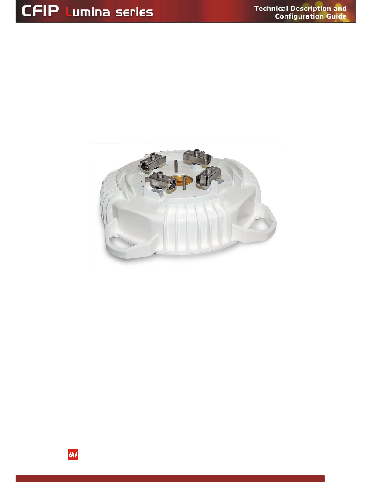
1.2.2 Mechanical Features
• Compact unit, 285x285x80mm (11.2x11.2x3.1in.), 3.9kg (8.5lbs), antenna adaption
backwards compatible with all CFM and CFQ series units
• 3 handles for user convenience
• Safe and easy to use 4 side locking arrangement
• All connectors on the side of the unit, always at 45
°
regarding vertical axis for both V and H
polarization
Figure 1.1: CFIP Lumina Full Outdoor Unit
1.2.3 Interfaces/Management
• CFIP Lumina unit provides 4 or 5 connectors (depending on model) and a grounding screw
• User and NMS traffic is carried over FO cable or Cat.5e cable (depending on the model)
• Ethernet traffic supports QoS and 4 priority queues, essential for ACM use
• User and NMS traffic could be treated as a single data stream or separated by tagging with
different VLAN tags
• Twin BNC connector of the unit enables terminal access into the unit
• BNC connector provides RSSI voltage signal to assist unit alignment
• Web, Telnet and SNMP are available as NMS interfaces into the unit
The CFIP Lumina Series Full Outdoor Unit Technical Description and Configuration Guide • Rev. 1.10 •
© SAF Tehnika JSC 2013
6
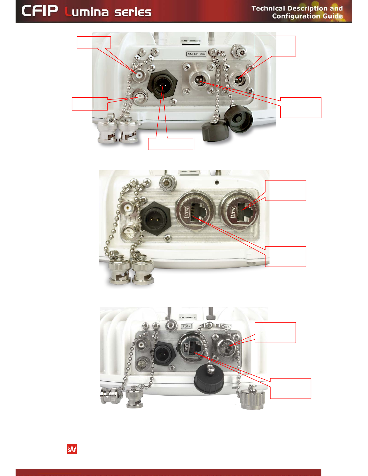
Figure 1.2: Optical CFIP Lumina FODU connectors
Figure 1.3: Electrical CFIP Lumina FODU connectors
Figure 1.4: Hybrid CFIP Lumina FODU connectors
RSSI port
Twin BNC
ODC port
(LAN1)
ODC port
(LAN2)
DC connector
RJ-45 port
(LAN4)
RJ-45 port
(LAN3)
RJ-45 port
(LAN3)
ODC port
(LAN2)
The CFIP Lumina Series Full Outdoor Unit Technical Description and Configuration Guide • Rev. 1.10 •
© SAF Tehnika JSC 2013
7
1.3 Radio Parameters
• CFIP Lumina is a good example of latest achievements in modem and transceiver
development, providing both excellent radio parameters (System Gain), due to use of QAM
modulations and efficient despite it consumes small amount of power Tx/Rx part of the
system.
• RSL Threshold at BER 10
-6
, 56MHz, 256QAM, 366Mbps: -64 dBm (CFIP Lumina 6GHz).
• ACM (Adaptive Coding and Modulation), hitless ACM opens new possibilities depending on
network designers strategy
• ATPC, Automatic Transmitter Power Control, for increased deployment density capability.
• Very high flexibility allows configuring the system to various channel bandwidths,
modulation schemes and capacity settings
1.4 Application Examples
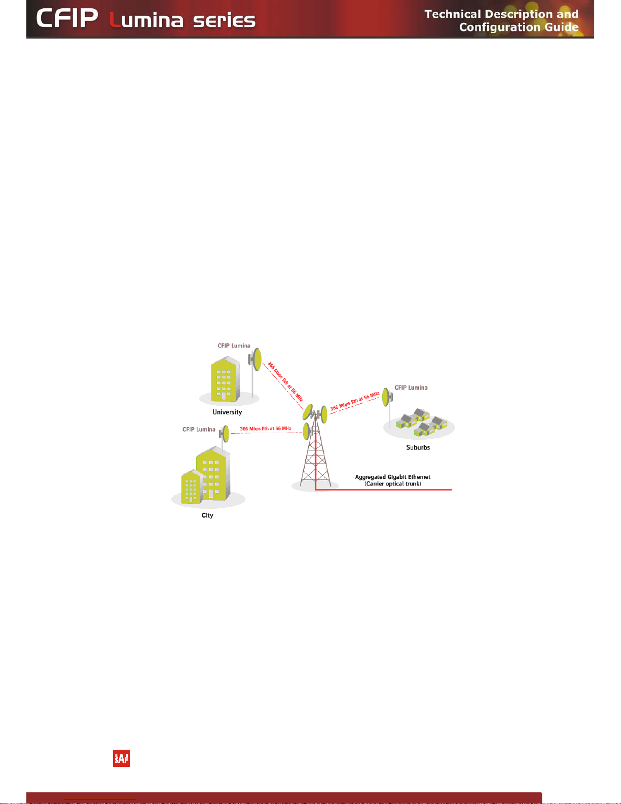
1.4.1 Carrier Gigabit Ethernet Trunk Distribution with CFIP Lumina
• Superb for extending Fiber Optics network over high capacity radio;
• Ideal for crossing mountains and interconnecting Gigabit Ethernet networks;
• Designed for building Ethernet backhaul network
Figure 1.5 CFIP Lumina application
1.4.2 2+0 protected link aggregation
A chain of 2+0 radios with full protection by employing single external Ethernet switch per site. For
more details refer to Chapter 4.5.
The CFIP Lumina Series Full Outdoor Unit Technical Description and Configuration Guide • Rev. 1.10 •
© SAF Tehnika JSC 2013
8
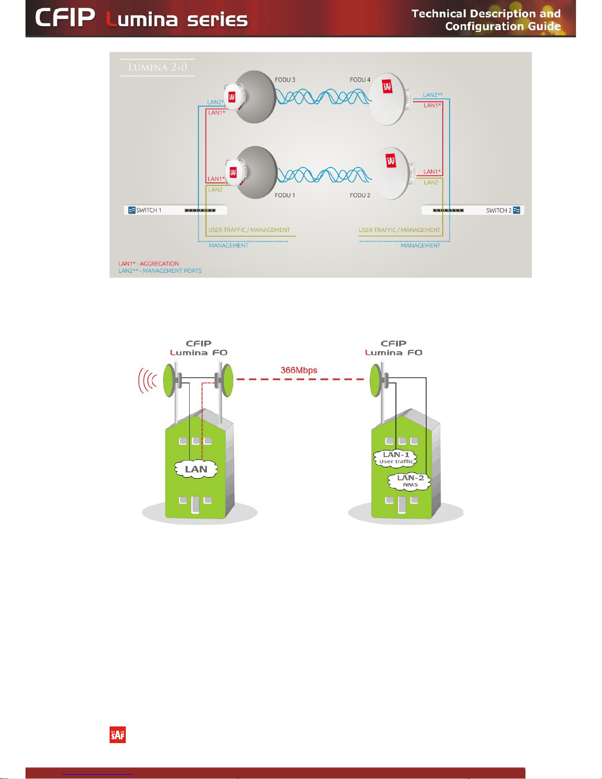
Figure 1.6 CFIP Lumina 2+0 link aggregation
1.4.3 CFIP Lumina East/West Chain
Figure 1.7 CFIP Lumina East/West chain
1.4.4 CFIP Lumina ring topology
• Utilization of STP protocol allows CFIP Lumina operation in ring topology
The CFIP Lumina Series Full Outdoor Unit Technical Description and Configuration Guide • Rev. 1.10 •
© SAF Tehnika JSC 2013
9
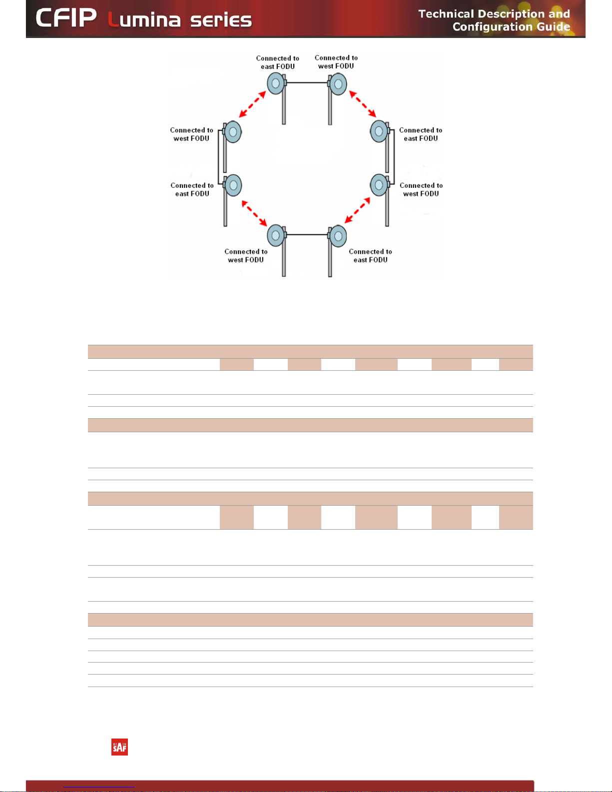
Figure 1.8 CFIP Lumina operation in ring topology
1.5 Technical specifications
III CFIP Lumina FODU technical spec ific a tio n
Frequency range (GHz) 6 7/8 10/11 13/15 17 18/23 24 26 38
Channel Bandwidths (MHz)
1
14 - 56
Modulation
4QAM / 16QAM / 32QAM / 64QAM / 128Q AM / 256QAM
Capacity (Mbps)
24 – 366
III Performance
Configuration
1+0,
Ring/Mesh (with STP),
2+0 (built-in Ethernet aggregation), 1+1 (Hot Stand-By)
Frequency stability (ppm)
+/-7
Traffic Interfaces
1 or 2 Gigabit Ethernet (electrical or optical)
III Ports
Flange
N-
type
UBR
84
UBR
100
UBR
140
Circular
13mm
UBR
220
Circular
10mm
UBR
260
UBR
320
Ethernet
Optical 1 or 2 ODC ports
Electrical 1 or 2 RJ-45
Hybrid 1 ODC and 1 RJ -45
DC power connector
2-pin waterproof circular
RSL port, RSSI, BNC
connector
Output voltage vs. RSL: 0 to 1.4V vs. -90 to -20dBm
Serial port for configuration
RS-232, Twin BNC connector
III Management features
Management port
Ethernet VLAN or Separate Ethernet (RJ-45 or ODC)
SNMP
Yes, SNMP traps, MIB, SNMP v1/v2c
EMS
Web based, HTTP
ATPC feature
Yes
ACM feature
Hitless 0ms
Loopbacks
Yes, modem, IF loopback
The CFIP Lumina Series Full Outdoor Unit Technical Description and Configuration Guide • Rev. 1.10 •
© SAF Tehnika JSC 2013
10

III Ethernet
Switch type
Managed Gigabit Ethernet Layer 2
Max frame size
9728 bytes
MAC table
4K entries; automatic learning and aging
Packet buffer
128KB; non-blo cking store&forward
Flow Control
802.3x
VLAN support
802.1Q (up to 4K VLAN entries)
QinQ (Double Tagging)
Yes
QoS
64 level DiffServ (DSCP) or 8 level 802.1p mapped in 4
prioritization queues with VLAN support
QoS queuing
Fixed or weighted (configurable ratio)
Spanning Tree Protocol
802.1D-2004 RSTP, 802.1Q-2005 MSTP
III Mechanical & Electrical
Stationary use
Ref. ETSI EN 300 019-2-4, class 4.1E; non weather-protected locations
Temperature Range
-33°C to +55°C
Dimensions: HxWxD, mm /
weight, kg
288x288x80 / 3.9
Built-in DC port surge
protection
Conforms to ETSI EN 301 489-1; EN 61000-4-5; IEC 61000-4-5
Input DC voltage
-40.5V to -57V DC (conforms to ETSI EN 300 132-2)
Max. power consumption
SP: 25-40 W; HP: 29-52 W
The CFIP Lumina Series Full Outdoor Unit Technical Description and Configuration Guide • Rev. 1.10 •
© SAF Tehnika JSC 2013
11
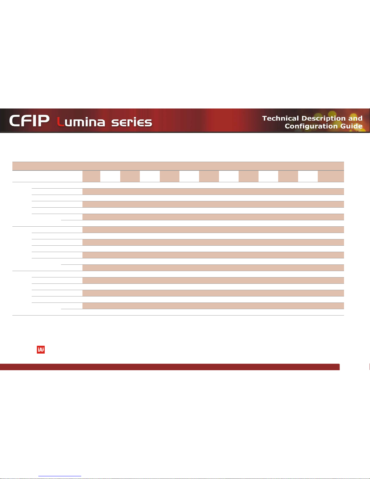
III CFIP Lumina Rx sensitivity, payload capacity
BW1,
MHz
Modulation FEC
2
6 GHz 7 GHz 8 GHz 10 GHz 11 GHz 13 GHz 15 GHz
174/18
GHz
23 GHz 24 GHz 26 GHz 38 GHz
Capacities,
Mbps
20
4QAM
Strong
-92
-91
-90.5
-90
-91
-91
-90.5
-91.5
-90.5
-90.5
-92.5
-86.5
24
16QAM
Strong
-84.5
-84.5
-84.5
-84
-85
-85
-84.5
-85.5
-83
-83
-86.5
-79
49
32QAM
Strong
-82
-82
-81.5
-81.5
-82
-82
-81.5
-82.5
-80.5
-80.5
-83.5
-76.5
63
64QAM
Strong
-80
-79
-78.5
-78.5
-79
-79
-78.5
-79.5
-78.5
-78.5
-81
-74.5
82
128QAM
Strong
-77
-76
-75.5
-75
-76
-76
-75.5
-76.5
-75.5
-75.5
-77.5
-71.5
98
256QAM
Strong
-73.5
-72
-72
-71.5
-72
-73
-72
-73
-72
-72
-74
-68
115
Weak
-70
-66
-65.5
-66.5
-67
-67
-66.5
-67.5
-68.5
-68.5
-68.5
-64.5
125
30
4QAM
Strong
-90
-89
-89
-88.5
-89.5
-89.5
-89
-89.5
-88.5
-88.5
-91
-84.5
37
16QAM
Strong
-84
-83
-82.5
-82.5
-83.5
-83
-82.5
-83.5
-82.5
-82.5
-84.5
-78.5
74
32QAM
Strong
-81
-80
-80
-79.5
-80.5
-80.5
-80
-80.5
-79.5
-79.5
-81.5
-75.5
95
64QAM
Strong
-78.5
-77
-77
-76.5
-77.5
-77.5
-77
-78
-77
-77
-79
-73
123
128QAM
Strong
-75.5
-74
-74
-73.5
-74.5
-74.5
-74
-75
-74
-74
-76
-70
147
256QAM
Strong
-72
-70.5
-70.5
-70.5
-71
-71
-70.5
-71.5
-70.5
-70.5
-72.5
-66.5
172
Weak
-69
-68.5
-65.5
-65.5
-67
-66.5
-66.5
-69
-67.5
-67.5
-70
-63.5
184
50
4QAM
Strong
-87.5
-86.5
-87
-86.5
-87.5
-87
-87
-87
-86
-86
-88.5
-82
63
16QAM
Strong
-81.5
-80.5
-80.5
-80
-81
-81
-80.5
-81.5
-80
-80
-82.5
-76
125
32QAM
Strong
-79
-77.5
-78
-77.5
-78.5
-78
-78
-78.5
-77.5
-77.5
-79.5
-73.5
158
64QAM
Strong
-76
-75
-74.5
-74.5
-75.5
-75
-75
-76
-74.5
-74.5
-77
-70.5
207
128QAM
Strong
-73
-72
-71.5
-71.5
-72.5
-72
-71.5
-72.5
-71.5
-71.5
-73.5
-67.5
249
256QAM
Strong
-69.5
-68
-68
-67.5
-68.5
-68.5
-68
-69.5
-68
-68
-70.5
-64
290
Weak
-66
-64.5
-63.5
-63.5
-64.5
-64.5
-64
-66
-64.5
-64.5
-67
-60.5
313
The CFIP Lumina Series Full Outdoor Unit Technical Description and Configuration Guide • Rev. 1.10 • © SAF Tehnika JSC 2013
12
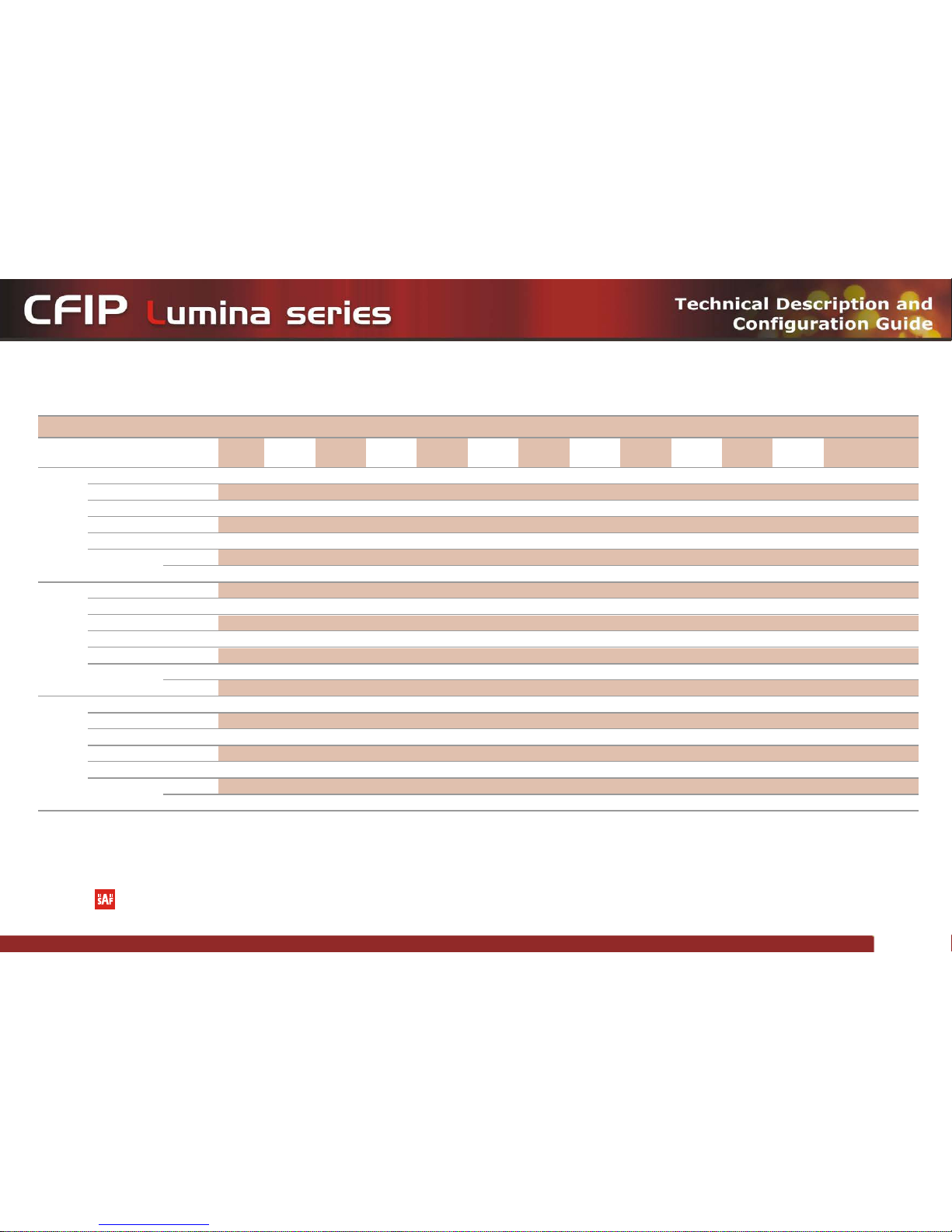
III CFIP Lumina Rx sensitivity, payload capacity
BW1,
MHz
Modulation FEC
2
6 GHz 7 GHz 8 GHz 10 GHz 11 GHz 13 GHz 15 GHz
174/18
GHz
23 GHz 24 GHz 26 GHz 38 GHz
Capacities,
Mbps
28
4QAM
Strong
-90.5
-89.5
-89
-88.5
-89.5
-89.5
-89
-90
-89
-89
-91.5
-85
35
16QAM
Strong
-84.5
-83
-83
-82.5
-83.5
-83.5
-83
-84
-83
-83
-85
-79
69
32QAM
Strong
-81.5
-80
-80
-80
-80.5
-80.5
-80.5
-80.5
-80
-80
-82
-76
88
64QAM
Strong
-79
-77.5
-77.5
-77
-78
-77.5
-77
-78
-77.5
-77.5
-79.5
-73.5
115
128QAM
Strong
-75.5
-74.5
-74
-73.5
-74.5
-74.5
-74
-75.5
-74
-74
-76.5
-70
139
256QAM
Strong
-72.5
-71
-70.5
-70.5
-71
-71
-70.5
-72
-71
-71
-73
-67
162
Weak
-69
-67
-66
-66
-67
-67
-66.5
-69
-67.5
-67.5
-70
-63.5
175
40
4QAM
Strong
-89
-87.5
-88
-87.5
-88
-88
-88
-88
-87.5
-87.5
-89.5
-83.5
50
16QAM
Strong
-82.5
-81.5
-81.5
-81
-82
-82
-81.5
-82.5
-81
-81
-83.5
-77
98
32QAM
Strong
-80
-78.5
-79
-78.5
-79.5
-79.5
-79
-79.5
-78.5
-78.5
-80.5
-74.5
127
64QAM
Strong
-77
-76
-75.5
-75.5
-76.5
-76
-76
-77
-75.5
-75.5
-78
-71.5
164
128QAM
Strong
-74
-73
-72.5
-72.5
-73.5
-73
-72.5
-73.5
-72.5
-72.5
-74.5
-68.5
196
256QAM
Strong
-70.5
-69.5
-69
-68.5
-69.5
-69.5
-69
-70.5
-69
-69
-71
-65
229
Weak
-68
-67
-64.5
-64.5
-65.5
-65
-65
-67.5
-66.5
-66.5
-68.5
-62.5
245
56
4QAM
Strong
-87
-85.5
-86
-85.5
-87
-86.5
-86
-87
-85.5
-85.5
-88
-81.5
72/673
16QAM
Strong
-81
-80
-79.5
-79.5
-80.5
-80
-79.5
-80.5
-79.5
-79.5
-82
-75.5
145/1353
32QAM
Strong
-78
-77
-77.5
-77
-78
-77.5
-77
-77.5
-76.5
-76.5
-79
-72.5
186
64QAM
Strong
-75.5
-74.5
-74
-73.5
-74.5
-74.5
-74
-75.5
-74
-74
-76
-70
241
128QAM
Strong
-72
-71
-71
-70.5
-71.5
-71.5
-71
-72
-70.5
-70.5
-73
-66.5
289
256QAM
Strong
-68.5
-67.5
-67
-66.5
-68
-67.5
-67
-68.5
-67
-67
-69.5
-63
337
Weak
-64
-63
-63
-62.5
-63.5
-63
-62.5
-64.5
-62.5
-62.5
-65
-58.5
366
The CFIP Lumina Series Full Outdoor Unit Technical Description and Configuration Guide • Rev. 1.10 • © SAF Tehnika JSC 2013
13
III CFIP Lumina Tx power
Modulation
Standard/High Tx Power, dBm
6, 7, 8 GHz
10, 11, 13,
15 GHz
17 GHz
4,5
18, 23, 26
GHz
24 GHz
4,5,6
38 GHz
4QAM +19 / +27 +19 / +25 -25…+5 +19
-20…0
+17
16QAM +18 / +26 +18 / +24 -25…+4 +18
-20…-1
+16
32QAM +17 / +25 +17 / +23 -25…+3 +17
-20…-2
+15
64QAM +15 / +23 +15 / +21 -25…+1 +15
-20…-4
+13
128QAM +15 / +23 +15 / +21 -25…+1 +15
-20…-4
+13
256QAM +12 / +20 +12 / +18 -25…-2 +12
-20…-7
+10
1
According to ETSI channel plan
2
Forward Error Correction (FEC) can be optimized either for sensitivity (Strong FEC) or for capacity (Weak FEC)
3
Higher capacity is available in 16QAM and 4QAM if using 32QAM-256QAM with ACM enabled
4
For non-degraded Rx sensitivity refer to radio frequency loopback procedure (pages 50-51) for maximum Tx level according to
Rx level observed.
5
Tx power should not exceed EIRP limitation. Please consult the local spectrum regulating authority.
6
Output Tx range may differ for previous hardware and software versions.
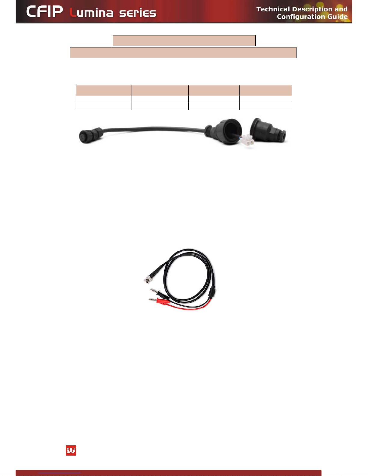
1.6 Cable Requirements
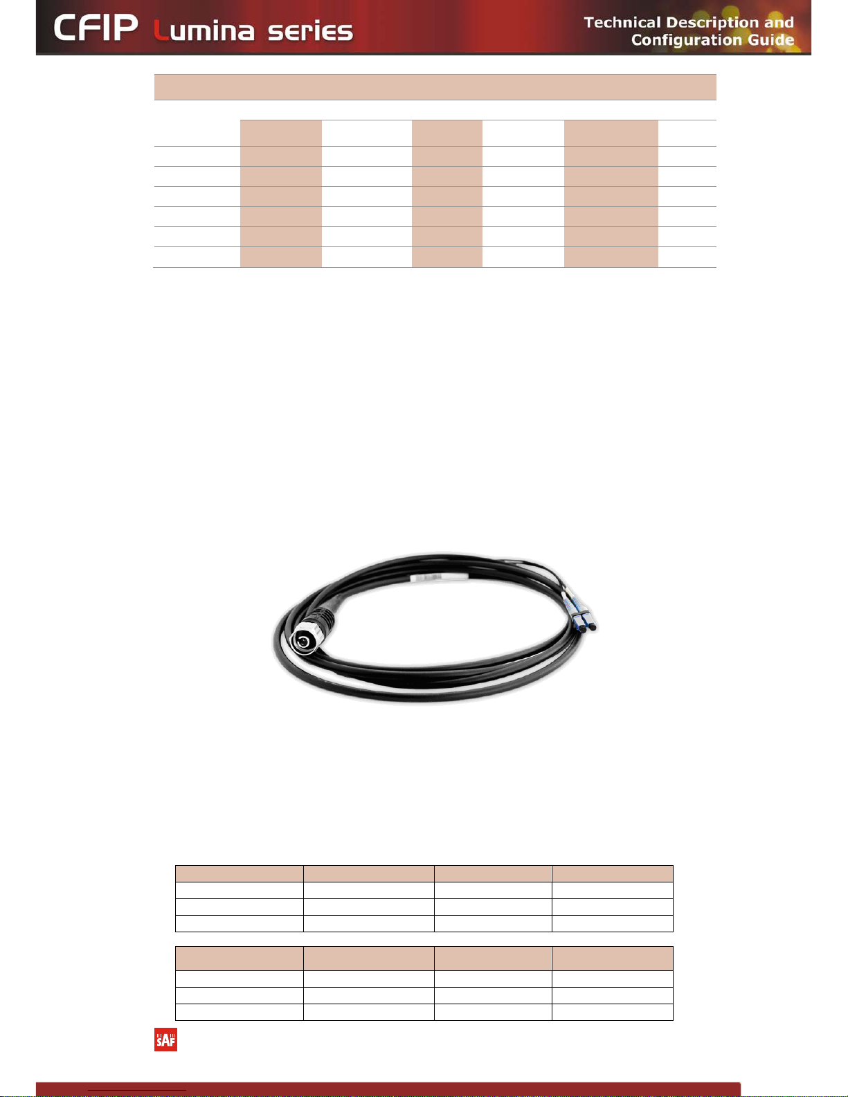
Fibre optics cable
Single mode 2 channel fibre with 2 fibre ODC plug is required for management and user data.
Length of the fibre optics cable using default single mode 1310nm SFP module is up to 10 kilometres
(6.2 miles). SAF Tehnika JSC can provide pigtail cable with ODC-LC connectors and length of 3, 10, 25
or 50 meters (10, 33, 82, 164 ft.).
Figure 1.9: CFIP Lumina ODC-LC cable
DC power cable
CFIP Lumina power supply voltage must be between 40.5–57 V DC. 2-wire outdoor cable with
dedicated 2-pin LTW DC connector assembly is needed to connect to CFIP Lumina. Any polarity can be
used. Preferable outer diameter of power cable is 6mm in order to match CFIP Lumina FODU side
connector. Cross-sectional area shall be not less than 0.75 square mm (AWG 18) for installations up to
260 meters / 853 feet (35W load power). If this area is less than 0.75 square mm, the allowed
maximum length of the cable is reduced due to a higher voltage drop.
Wire cross section
Lmax @ 50W
Lmax @ 35W
Lmax @ 25W
0.75mm2
180m / 590ft
260m / 853ft
380m / 1246ft
0.5mm2
120m / 393ft
180m / 590ft
250m / 820ft
0.25mm2
60m / 196ft
90m / 295ft
125m / 410ft
AWG Lmax @ 50W Lmax @ 35W Lmax @ 25W
18
206m / 677ft
294m / 967ft
412m / 1353ft
20
129m / 426ft
185m / 608ft
259m / 851ft
24
51m / 168ft
73m / 240ft
102m / 337ft
The CFIP Lumina Series Full Outdoor Unit Technical Description and Configuration Guide • Rev. 1.10 •
© SAF Tehnika JSC 2013
14
(!) Power connector can be soldered in any polarity layout.
Optional accessory power adapter cable with screw terminal (P/N I0ACGE04/I0ACGE05
(0.3/1.0m)) does not require soldering and can accept power cable up to AWG14 with maximum
cable length up to 745m / 2444ft (35W):
AWG Lmax @ 50W Lmax @ 35W Lmax @ 25W
14
521m / 1711ft
744m / 2444ft
1043m / 3422ft
16
327m / 1076ft
468m / 1537ft
655m / 2151ft
Figure 1.10: CFIP Lumina power adapter cable with screw terminal
RS-232 Serial Connection
The ASCII console must be connected to the RS-232 serial port with Twin-BNC connector. This
requires a twisted pair (TP) cable with common shield (foil and plaited shield); the cable must be
suitable for Twin-BNC connector.
Using a proper cable, the operation is guaranteed for up to 10 m (33 ft.) of cable.
RSSI BNC
To connect the digital multimeter to the CFIP Lumina RSSI port in order to adjust the antenna
alignment, a coaxial cable with BNC connector on one end and appropriate termination on other end
can be used (see example in Figure 1.4).
Figure 1.11. Cable for connecting the voltmeter to the CFIP Lumina RSSI port
1.7 AC/DC power adapter requirements
Table below helps choosing the most appropriate power adapter from SAF Tehnika accessories list for
standard and high power CFIP Lumina radios. Note that table summarizes maximum power
consumption; normally consumption is 10-20% less. One should be aware that High Power versions of
the CFIP Lumina radios in some frequencies have maximum power consumption above 50 W and such
aspects as power losses in the cable from AC/DC adapter to FODU and loses in PoE injector/splitter, if
such is used, must be taken in to consideration. For further details on power adapters please see
table in Chapter 11
(!) It is mandatory requirement to ground power supply of CFIP Lumina FODU appropriately.
The CFIP Lumina Series Full Outdoor Unit Technical Description and Configuration Guide • Rev. 1.10 •
© SAF Tehnika JSC 2013
CFIP Lumina high power
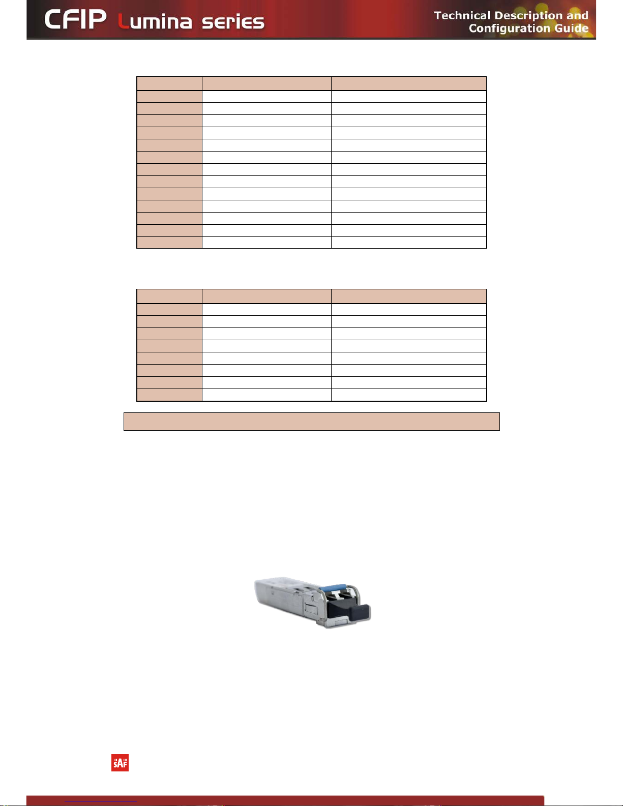
1.8 SFP (Small Form-Factor Pluggable Transceiver)
Initial version of CFIP Lumina is equipped with internal 1310 nm Single-mode Transceiver, (1000BaseLX) SFP module (P/N I0AOM001) with following features:
- Compliant with IEEE 802.3z Gigabit Ethernet Standard;
- Compliant with Fiber Channel 100-SM-LC-L standard;
- Industry standard small form pluggable (SFP) package;
- Duplex LC connector;
- Class 1 laser product complies with EN 60825-1.
Figure 1.12. CFIP Lumina SFP 1310nm SM transceiver
On demand CFIP Lumina at factory premises can be equipped with alternative SFP modules.
Specifications of available SFP modules:
CFIP Lumina high power
Band (GHz)
Max power consumption (W)
Min recommended PSU power (W)
6
40
60
7 33 60
8 33 60
10 40 60
11
40
60
13 34 60
15 34 60
17 34 60
18 32 60
23 34 60
24 29 60
26 32 60
38
37
60
Band (GHz)
Max power consumption (W)
Min recommended PSU power (W)
6 52 80
7 45 60
8
45
60
10 52 80
11 52 80
13 46 60
15
46
60
38 49 80
(!) It is mandatory requirement to ground power supply of CFIP Lumina FODU appropriately.
The CFIP Lumina Series Full Outdoor Unit Technical Description and Configuration Guide • Rev. 1.10 •
© SAF Tehnika JSC 2013
Part number Product name Wavelength Media Distance Application Tx power
RSL
threshold
Temp
I0AMOM01
SFP 850nm MM
Transceiver 1000Base-
SX 3.3V
850 nm MMF
550 m / 1800
ft.
1000Base-SX
-9.5..-4
dBm
<-18 dBm
-20..+85C -
4..185F
I0AOM001
SFP 1310nm SM
Transceiver1000Base-
LX 3.3V
1310 nm SMF
10 km / 6.21
miles
1000Base-LX
-9.5..-3
dBm
<-20 dBm
-40..+85C
-40..185F
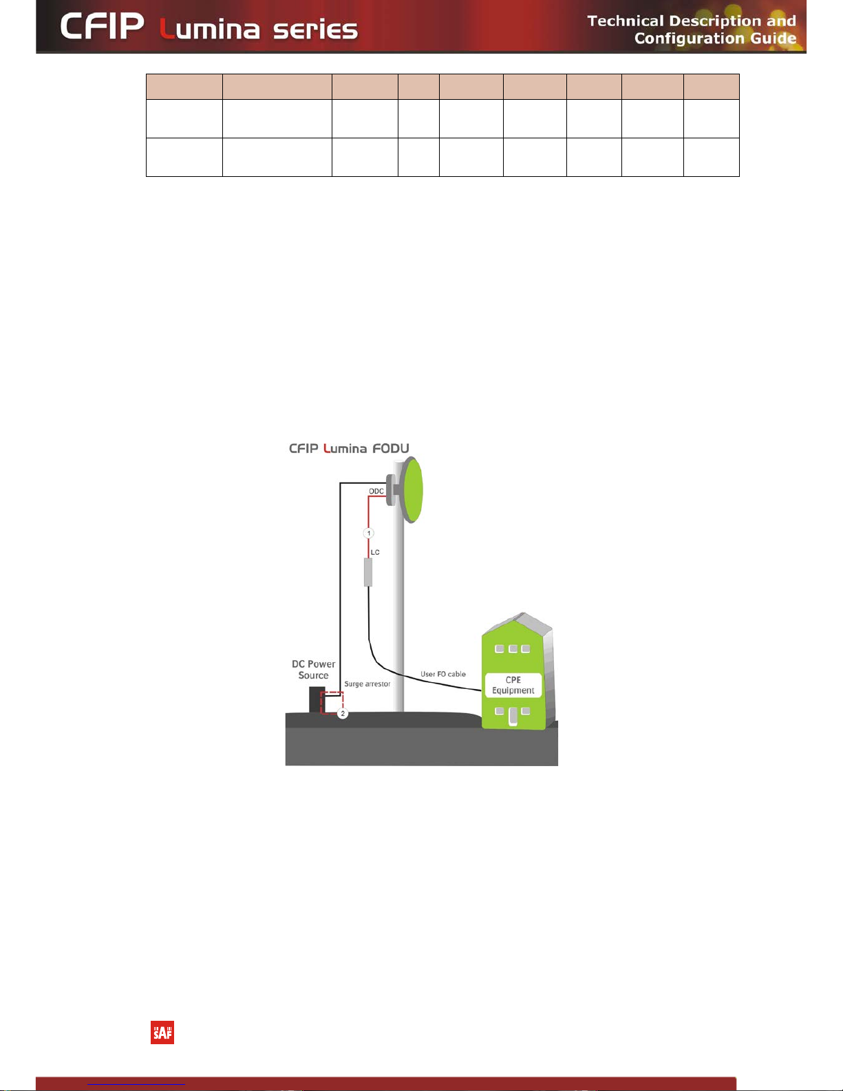
1.9 CFIP Lumina with FO Gigabit Ethernet Port
1. Lumina and customer equipment connectivity options via FO cables:
• by ordering ODC-2xLC outdoor patch cord of appropriate length 3 – 200
meter patch cords can be ordered)
• by using outdoor box to connect ODC-2xLC to LC connectorized FO cable to
equipment at customer premises
• by welding ODC terminated FO cable to FO cable to equipment at customer
premises and appropriately sealing the weld
2. As Lumina FODU DC-in port has a built in surge arrestor solution, SAF only recommends to
use surge arrestor at the DC source end of the cable
Figure 1.13. Optical CFIP Lumina site
1 – ODC-LC cable
2 – Surge arrestor on power cable
1.10 CFIP Lumina with RJ-45 Gigabit Ethernet Port
Electrical Gigabit interface is vulnerable to overvoltage jumps, thus elevated surge protection should
be implemented – one surge arrestor should be placed at FODU, another before user equipment.
Configuration with separate power and Ethernet cables is shown on Figure 1.13.
Proprietary PoE injector + splitter solution provides sufficient protection of both power and Ethernet
interfaces, besides allows using single cable to the splitter located near CFIP Lumina FODU (Figure
1.14).
The CFIP Lumina Series Full Outdoor Unit Technical Description and Configuration Guide • Rev. 1.10 •
© SAF Tehnika JSC 2013
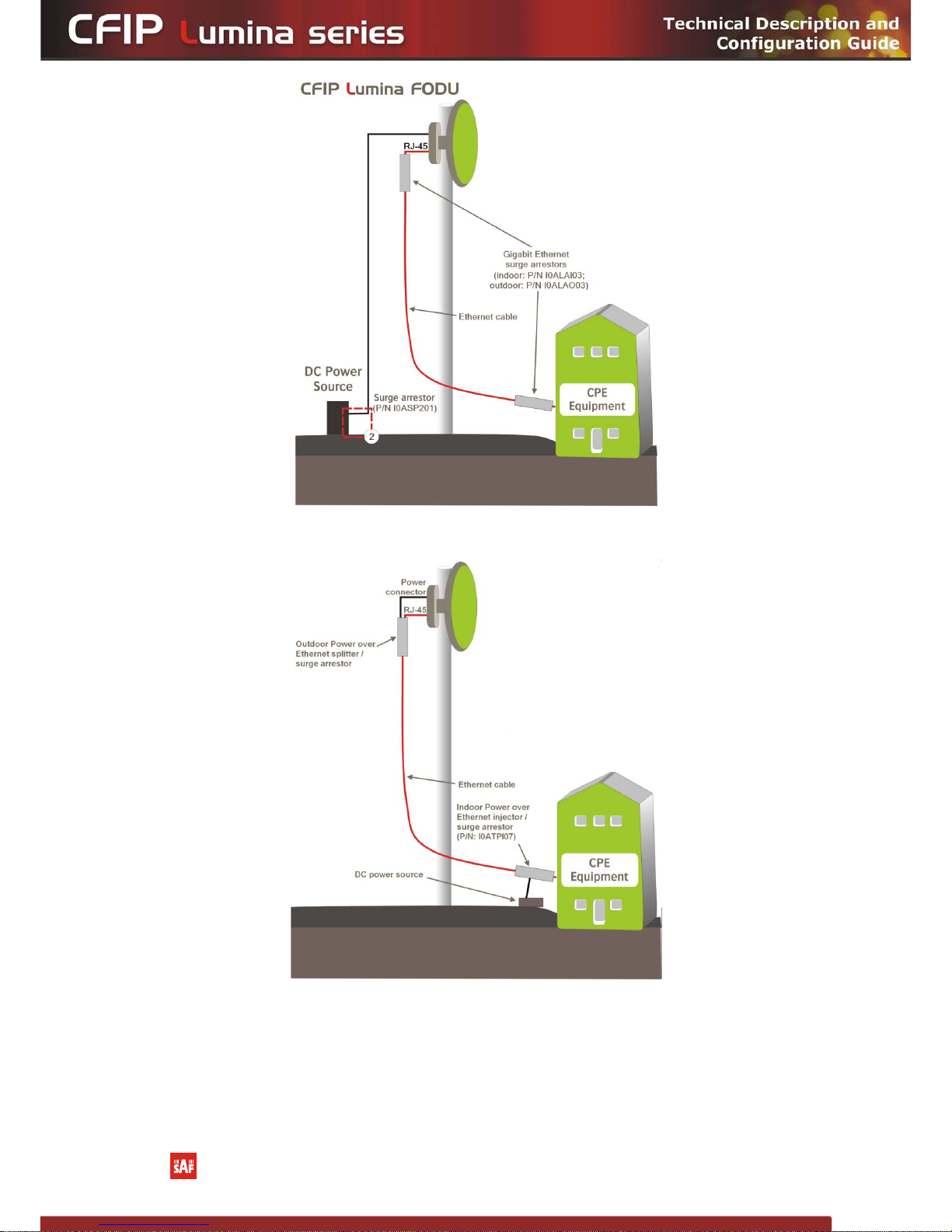
Figure 1.14. Electrical CFIP Lumina site
Figure 1.15. Electrical CFIP Lumina site
1.11 Labelling
The label can be found on the front side of the unit.
The label contains the following information (see samples in the picture below):
The CFIP Lumina Series Full Outdoor Unit Technical Description and Configuration Guide • Rev. 1.10 •
© SAF Tehnika JSC 2013
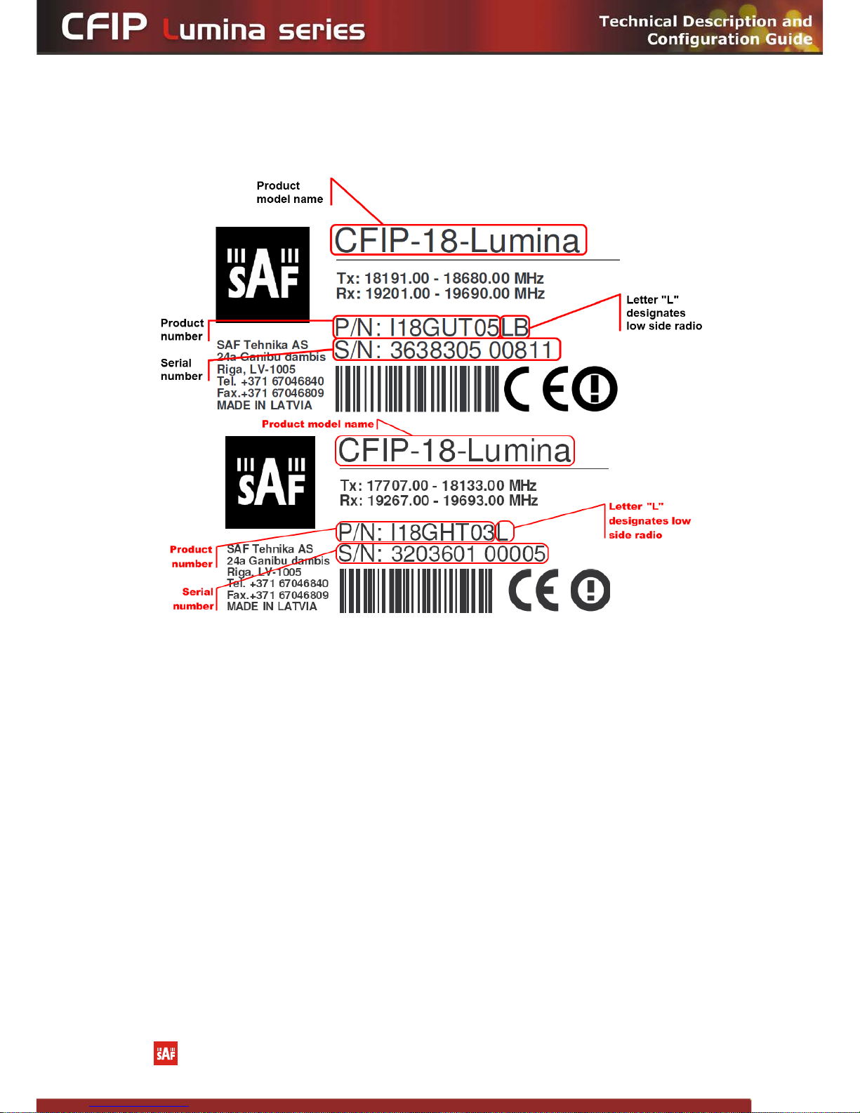
- Model name (“CFIP-18-Lumina”). The FODU model name example is:
- CFIP-18-Lumina for 18GHz FODU,
- CFIP-23-Lumina for 23GHz FODU, etc
- Product Number (I18GUT05LB): product number contains information in which band side (L,
H) the FODU operates. Letters A, B, C or D indicate specific subband.
- Unit Serial Number (3638305 00811); the serial number uniquely identifies the unit.
Figure 1.16. Label of the CFIP Lumina Low band side, operating in 18 GHz band
P/N Translation:
“I” designates CFIP series product;
“18” designates Frequency range (18 GHz) of the Unit;
“G” designates standard power CFIP Lumina with 20-56 MHz channel bandwidth support;
S – high power CFIP Lumina with 20-56 MHz channel bandwidth support;
N – standard power CFIP Lumina with 14-56 MHz channel bandwidth support;
H – high power CFIP Lumina with 14-56 MHz channel bandwidth support
“H” designates Gigabit Ethernet 1x Electrical;
E – 2x electrical;
O – 2x optical, SM;
M – 2x optical, MM;
L – 1x optical, SM;
N – 1x optical, MM;
U – 1x optical, SM + 1x electrical;
J – 1x optical, MM + 1x electrical
“T” designates no capacity limitation;
N - capacity limitation up to 50Mbps;
L – capacity limitation up to 100Mbps;
The CFIP Lumina Series Full Outdoor Unit Technical Description and Configuration Guide • Rev. 1.10 •
© SAF Tehnika JSC 2013

K – capacity limitation up to 184Mbps
“03” designates the version number of the Unit;
“L” designates the band side in which FODU operates (H, L);
Please note that frequency range is set from the central frequency of the first 20 MHz channel to
the central frequency of the last 20 MHz channel (see the Figure below).
Figure 1.17. Frequency range of low and high side CFIP Lumina 18 GHz FODUs
The Figure explains Tx frequency range of low and high side CFIP Lumina 18 GHz radios.
The CFIP Lumina Series Full Outdoor Unit Technical Description and Configuration Guide • Rev. 1.10 •
© SAF Tehnika JSC 2013
2 Installation and configuration
There are four ways to adjust and read settings and operation parameters of the CFIP Lumina
equipment:
1. using Web terminal (Ethernet interface),
2. using Telnet terminal (Ethernet interface),
3. using NMS or SNMP terminal (Ethernet interface), or
4. using ASCII console connected to the serial port.
It is highly recommended to perform initial configuration in the lab – using testing suite or bouncing
signal from the ceiling.
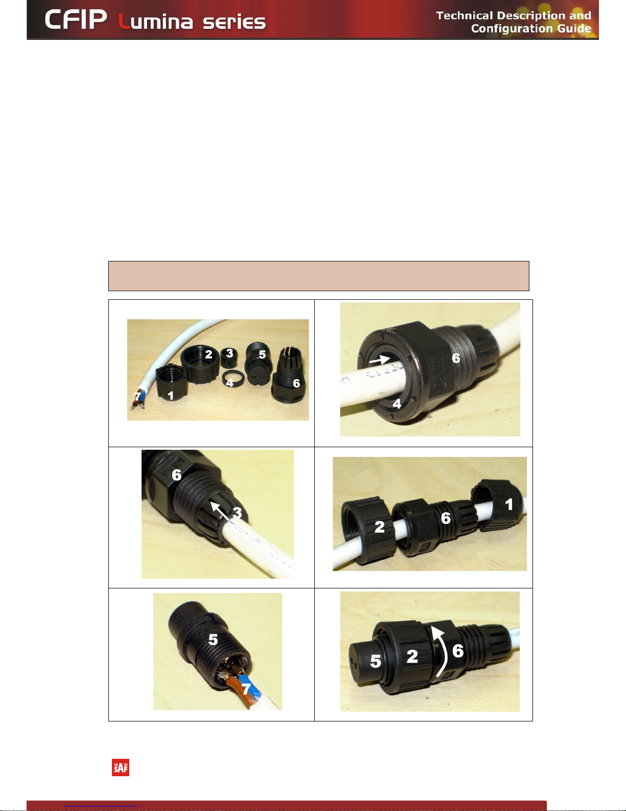
2.1 Assembling CFIP Lumina weatherproof DC Connector
(!) Assembling of weatherproof DC connector does not require any additional tools; all below mentioned
operations can be done manually.
1
2
3
4
5
6
The CFIP Lumina Series Full Outdoor Unit Technical Description and Configuration Guide • Rev. 1.10 •
© SAF Tehnika JSC 2013
7
Figure 2.1. Assembling weatherproof DC power connector
1. You will need: (1-6) DC connector components and (7) ready 2-wire DC power cable.
2. Wider sealing rubber ring should be fitted inside from the front end of (6).
3. Narrower sealing rubber ring should be fitted inside from the rear end of (6).
4. Parts of the DC connector should be put on the cable in the sequence as shown
5. DC power cable should be soldered in any polarity layout.
6. Afterwards, part (6) should be tightened on to part (5).
7. Assembled DC power connector after tightening the last part (1)
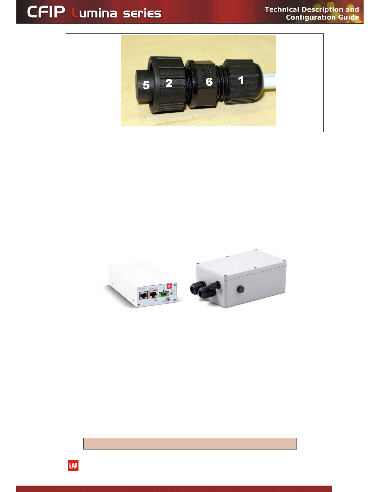
2.2 Passive Power over Ethernet injector and splitter
Optionally to power up CFIP Lumina you can use SAF proprietary Power over Ethernet injector
and splitter set (P/N I0ATPI11; I0ATPS03).
Figure 2.2. Power over Ethernet injector and splitter
Both units are designed to be used together providing Gigabit Ethernet and power interfaces via
single Ethernet cable (Cat5e or better) to CFIP Lumina FODU. Instead of running two separate cables
for power and Ethernet, this solution allows to run just one cable from inside equipment to the radio
outside.
The non-IEEE PoE injector and splitter both have a built-in lightning and surge protection
preventing transient over-voltages from damaging CFIP Lumina radio and user’s indoor equipment.
Polarity layout is indicated above power connector and the injector is protected against reversed
polarity.
The injector has a built-in DC/DC converter which can be manually with a jumper switched
between two modes. In the first mode output voltage is the same as input. In the second mode input
voltage can vary from 30 to 50 V, but on the output it will be stabilized to 55 V. The second mode is
designed to diminish the negative influence of long cable or insufficient input voltage from power
supply.
(!) Power supply should be connected in polarity layout depicted on injector’s housing.
The CFIP Lumina Series Full Outdoor Unit Technical Description and Configuration Guide • Rev. 1.10 •
© SAF Tehnika JSC 2013
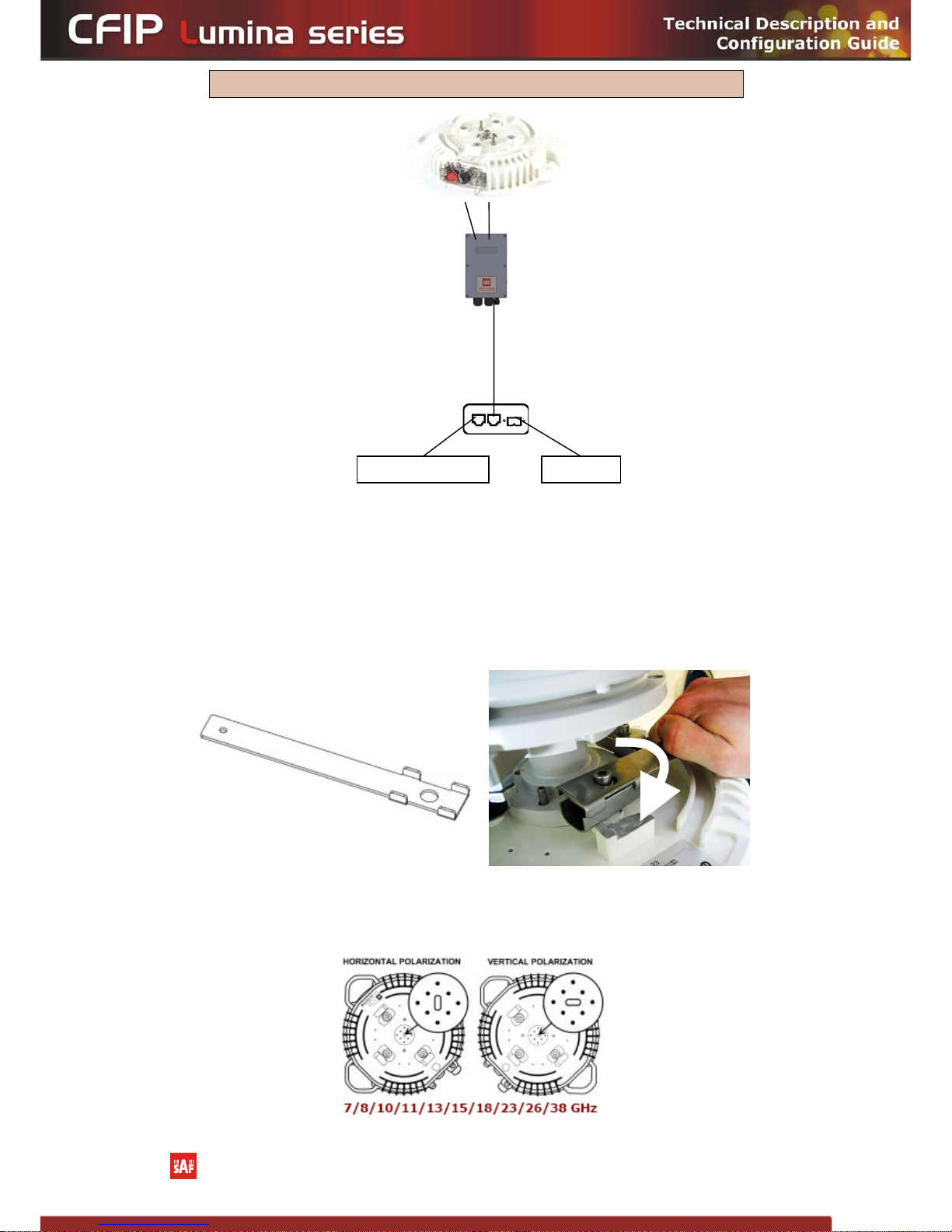
Figure 2.3. Interconnection of Power over Ethernet injector, splitter and CFIP Lumina
2.3 Attaching CFIP Lumina FODU to antenna
You need only tightening one tool to attach CFIP Lumina to the antenna.
Use two guidance pins for fixing polarization and 4 side lockings for attachment. Lockings should be
tightened in diagonal sequence.
Licensed frequency bands 6 – 38 GHz
Pair radios in licensed frequency bands 6 - 38 GHz use same polarization for Tx/Rx channels on both
ends of the link – either horizontal, or vertical.
Gigabit Ethernet
DC
Gigabit Ethernet
+
DC
DC
Gigabit Ethernet
The CFIP Lumina Series Full Outdoor Unit Technical Description and Configuration Guide • Rev. 1.10 •
© SAF Tehnika JSC 2013
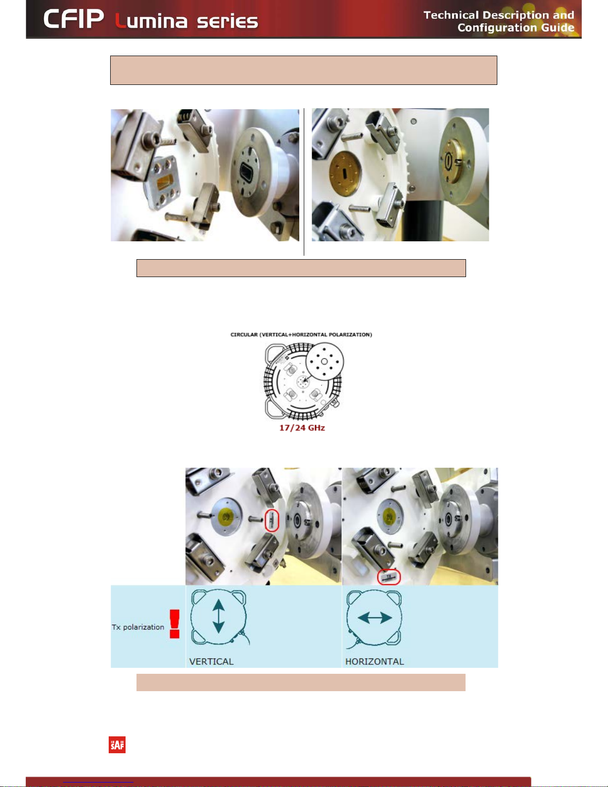
(!) In case of 6GHz (N-Type connectors) polarization is determined by antenna and should be same
on both ends of the link.
Examples:
7GHz (vertical polarization) 23GHz (horizontal polarization)
(!) Lockings should be positioned in way it is shown on picture.
Unlicensed frequency bands 17/24 GHz
Pair radios in unlicensed frequency bands 17/24 GHz use both polarizations simultaneously via
circular flange – radios on opposite side of the link should be installed with 90 degree offset.
Example of 24GHz antenna and FODU mating on local and remote sides of the link and appropriate
indication in Web GUI:
(!) Lockings should be positioned in way it is shown on picture.
The CFIP Lumina Series Full Outdoor Unit Technical Description and Configuration Guide • Rev. 1.10 •
© SAF Tehnika JSC 2013
2.4 Resetting the CFIP Lumina
Depending on the method used, the user may reset the whole terminal or the management
controller individually, see table below for details.
Reset action unplugging power source. Restarts both the multiplexer module and the management
module. Resets all management counters.
Resetting with button in
Web GUI ‘Configuration System
configuration’ window or using command
prompt command “system reset”
Restarts CPU of the management controller. Resets all
management counters.
Resetting with command prompt command
“system reset cold”
Restarts modem and CPU of the management controller. Resets
all management counters.
2.5 Web Interface
This section describes operation of Web interface.
2.5.1 ODC Port
ODC port is used to connect the CFIP Lumina to a PC or Ethernet network for Web, SNMP and
Telnet management.
(!) The length of single mode FO cable can be up to 10 kilometres (6.2 miles).
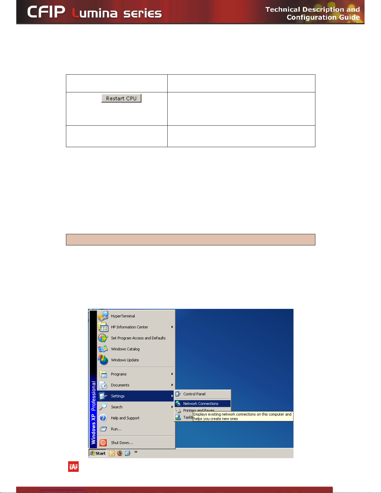
2.5.2 Ethernet Management Connection Configuration
Before you proceed to initial link setup with Web GUI, you must perform Ethernet connection
configuration by following these steps:
1) In “MS Windows” operational system go to Start Settings Network connections (or
Start Settings Control panel Network connections)
The CFIP Lumina Series Full Outdoor Unit Technical Description and Configuration Guide • Rev. 1.10 •
© SAF Tehnika JSC 2013
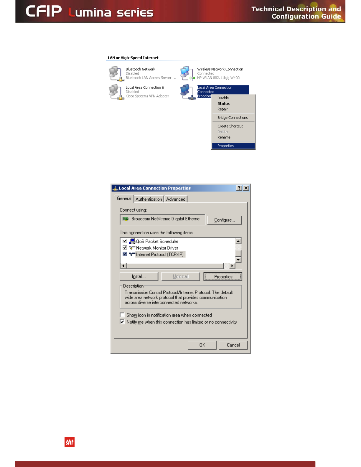
Figure 2.4.
2) Find ‘Local Area Connection’, click right mouse button on it and choose ‘Properties’
Figure 2.5.
3) Click on ‘Internet Protocol (TCP/IP)’ from the list in the dialog box and then click on
‘Properties’
Figure 2.6.
4) In the dialog box enter the following values (so that your PC is in the same subnet as
default CFIP Lumina addresses):
The CFIP Lumina Series Full Outdoor Unit Technical Description and Configuration Guide • Rev. 1.10 •
© SAF Tehnika JSC 2013
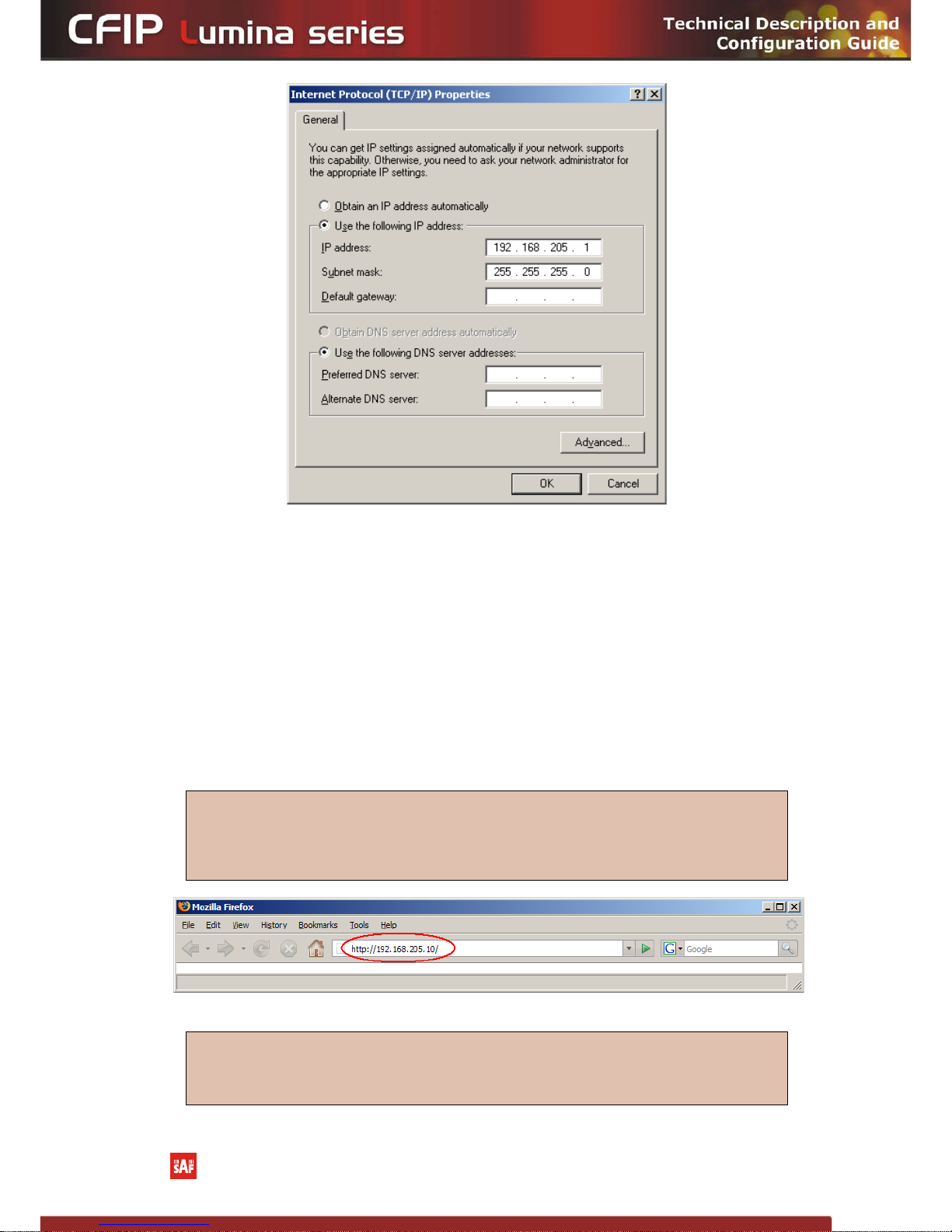
Figure 2.7.
Now you are ready to connect to Web GUI or establish Telnet connection.
2.5.3 Connecting to Web Interface
It is recommended to use the following web-browsers (and all later versions):
• IE v. 6.0
• Mozilla Firefox v. 2.0.0.11
• Safari v. 3.0
• Opera v. 9.50
• Google Chrome
After web browsers selection, open it and enter address of the FODU (Figure 2.8).
(!)
It is important to know the Side parameter of the FODU to which you want to connect; whether
the factory settings are loaded in FODU.
If Low Side -> IP: 192.168.205.10
If High Side -> IP: 192.168.205.11
Figure 2.8. CFIP Lumina IP address
(!) The default username and password for Web access are:
– username: admin
– password: changeme
The CFIP Lumina Series Full Outdoor Unit Technical Description and Configuration Guide • Rev. 1.10 •
© SAF Tehnika JSC 2013
If the IP address is correct and you have suitable browser version, you will see confirmation text.
After confirmation you will be redirected to Web interface page. In case of not valid IP address you
will not obtain the configuration interface. In case your browser is not accepted, you will see the text
informing about that. You can push the button “Continue Anyway” to be redirected to Web interface
page.
At first “ConfigurationConfiguration wizard” should be run in order to perform basic link
configuration (by default Tx power is disabled and parameters of remote side will not be seen).
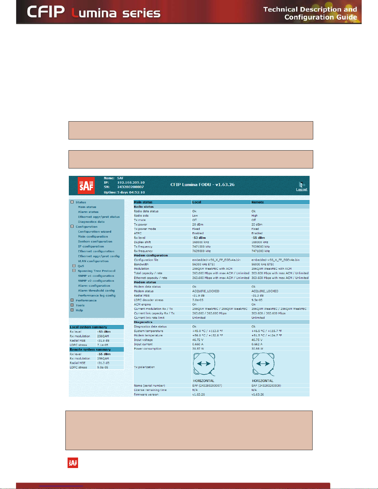
If configuration was made correct, you will see the main window of the WEB Interface. If there
are problems in the field displaying Local and/or Remote system values (configured values are not the
same for Local and Remote, or there is a problem with parameter value), the appropriate cell will be
highlighted in red colour.
Figure 2.9. Web Interface - main window
(!) Note that CFIP Lumina 17 and 24 GHz (unlicensed) utilize both polarizations, and radios must be
installed with 90 degrees offset regarding remote side. This, as well as position of cables can be
verified in Main status Tx polarization row. Licensed 6/7/8/10/11/13/15/18/23/26/38 GHz radios on
contrary should be installed with same polarization on both ends of the link (for 6GHz polarization is
determined by antenna).
(!) If you are not obtaining the correct Web page, try to clear browser cookies, cache and offline
data and restart the browser.
(!) All the commands executed from Web GUI will be interpreted as CLI commands and will be
executed as in CLI.
The CFIP Lumina Series Full Outdoor Unit Technical Description and Configuration Guide • Rev. 1.10 •
© SAF Tehnika JSC 2013
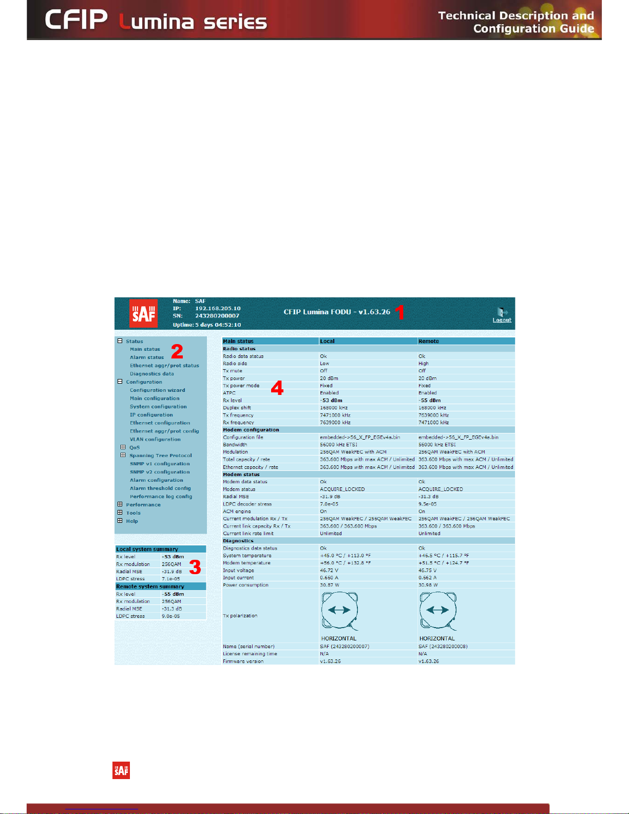
2.5.4 Interface Description
WEB interface consists of four parts, they are:
1. Top panel, that allows to log out and gives information about device type, software version,
device name, IP, serial number and uptime;
2. Menu panel that is used to open links to other pages;
3. Status summary for local and remote devices: this section is available while browsing other
pages.
4. The main panel where the new pages selected from the menu panel are loaded for display;
Also, special marks are used:
– Entries highlighted in red indicate that specific parameters do not comply with the norms of
normal operation. For example: value is out of range; local value is not equal to the remote
value and vice versa (only in some places); no value data (N/D).
– If the entry is highlighted in yellow, this means warning condition.
– If the value place reads ‘N/D’, this means ‘No Data’.
– If the value place reads ‘N/A’, this means ‘Not Available’.
Figure 2.10. Web Interface - main window with section numbering
2.5.5 Command Execution
There is a “IP configuration” page shown in Figure 2.11. The entire page is divided into smaller
fragments:
1. The header of page;
The CFIP Lumina Series Full Outdoor Unit Technical Description and Configuration Guide • Rev. 1.10 •
© SAF Tehnika JSC 2013
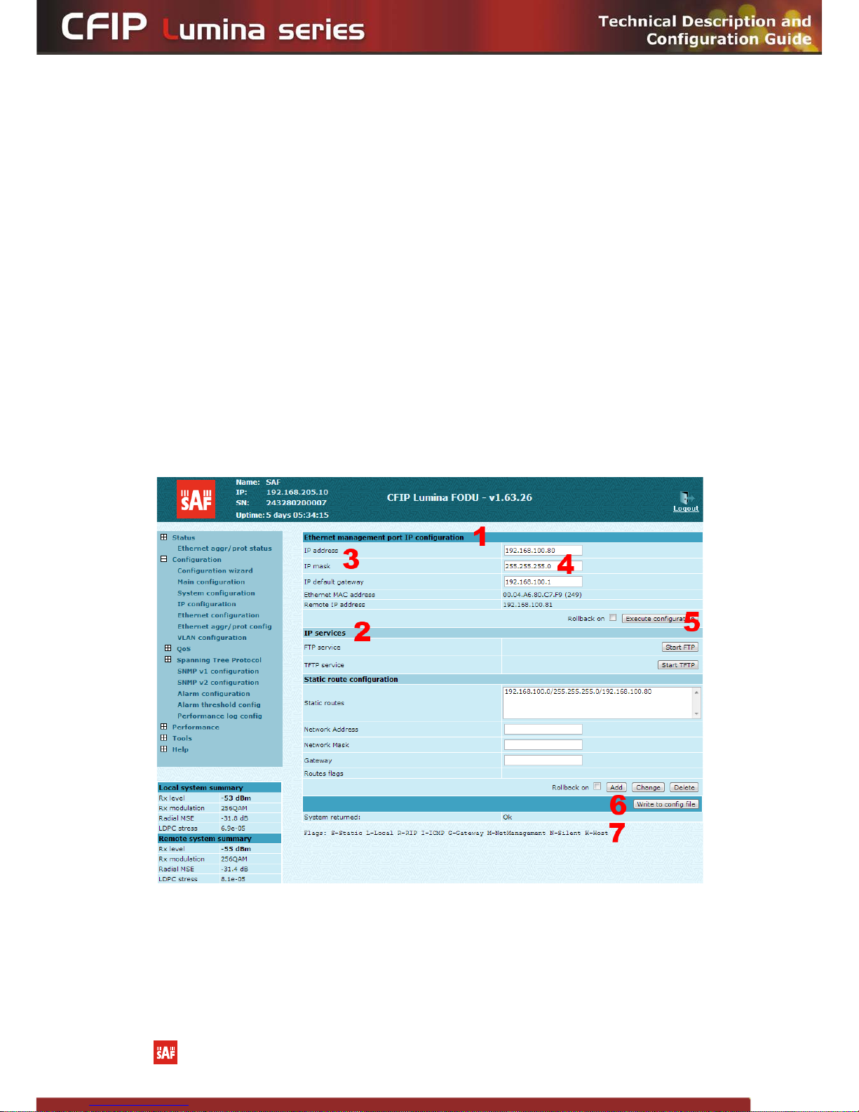
2. Sub-header of single type configuration parameters;
3. Configuration parameter name;
4. Configuration parameter current value;
5. Execution controls related to a single type configuration parameters.
6. Write to config file button, which generates “cfg write” CLI command, which saves changed
configuration;
7. Comments (not on every page).
„Execute for both” is available in “Main configuration” section during configuration of modem or
ATPC parameters for local and remote radio sides simultaneously.. Connection between both
management CPUs must be established in order to complete successfully configuration execution for
both sides.
„Rollback on” feature is intended to maintain connectivity of the CFIP link by cancelling last
erroneous configuration changes and reverting to previous successful configuration used. Rollback
will activate only if you lose connection to WEB interface of CFIP Lumina after configuration changes
applied, and reverting process will take approx. 3 minutes.
After parameter value editing, when the focus from this object is removed, this parameter value
edit box may be highlighted in red, meaning that entered value is not valid.
If „Execute configuration” or „Execute for both” buttons are pressed, and one or several
configuration values edit boxes is/are highlighted in red, the user will see error message with the
explanation text.
Figure 2.11. Web Interface - IP configuration page with numbering
2.5.6 Initial Configuration with Web GUI
The connected laptop should be in the same subnet as manageable CFIP Lumina in order to
observe it. Therefore laptop Ethernet port settings should be set as follows: (in ‘Microsoft Windows’
The CFIP Lumina Series Full Outdoor Unit Technical Description and Configuration Guide • Rev. 1.10 •
© SAF Tehnika JSC 2013
 Loading...