

Page 1

CFM-34-REBM
Modular Fast Ethernet Bridge
Indoor Unit Management System
Technical Description and Configuration
Guide
Software Version 3.12
SAF Tehnika A/S 2003
Page 2

Table of Contents
CFM-34-REBM Fast Ethernet Bridge Indoor Unit Overview....................... 3
1
2 Fast Ethernet Bridge IDU Appearance...................................................... 4
2.1 Labelling ............................................................................................. 7
3 Interface modules.................................................................................... 8
3.1 V.35 Interface Module........................................................................... 8
3.1.1 Configuring V.35 Module.................................................................. 8
3.1.2 V.35 Interface Module LEDs ............................................................. 9
3.2 E1 Interface Module ............................................................................10
3.2.1 Configuring E1 Interface Module ......................................................10
3.3 REB Interface Module ..........................................................................11
4 Management Interfaces ......................................................................... 12
4.1 Reading the LEDs................................................................................12
4.2 LCD/Keypad .......................................................................................12
4.2.1 “Status Display” Mode of the IDU LCD Management Interface ..............12
4.2.2 “Setup” Mode of the IDU LCD Management Interface ..........................14
4.2.3 Reset Functions.............................................................................15
4.3 RS-232 Serial Management Port ............................................................16
4.4 Ethernet Management Port ...................................................................19
4.4.1 Web Interface ...............................................................................19
4.4.2 SNMP Interface .............................................................................22
4.4.3 Command Line Interface for Telnet/ASCII consoles.............................26
4.5 Alarm Interface Port ............................................................................33
4.6 Performing Loop-back Tests..................................................................34
4.6.1 Ethernet interface loop tests............................................................34
4.6.2 Base-band and Radio loop tests .......................................................35
4.6.3 Interface Module loop tests .............................................................37
4.7 DIP Switch Settings.............................................................................39
4.8 Configuring Management Service Channel ..............................................40
4.9 Algorithm of LCD Operation ..................................................................43
4.10 Replacing the Indoor Unit .....................................................................44
4.11 Updating Management Software............................................................44
4.12 Default Settings ..................................................................................45
5 Configuring Radio Parameters ............................................................... 46
5.1 Default ODU Settings...........................................................................46
5.2 Configuring Tx Frequency.....................................................................46
5.3 Configuring Tx Power...........................................................................47
5.4 RSSI Voltage-Rx Signal Level Relation....................................................47
6 Pinouts................................................................................................... 48
7 Mechanical Data..................................................................................... 51
8 Frequency Channel Arrangement ........................................................... 52
9 SAF Tehnika A/S Contacts...................................................................... 54
10 References........................................................................................... 55
10.1 Technical Description...........................................................................55
10.2 Configuration Guides ...........................................................................55
10.3 Management Software Update Guide......................................................55
Modular Fast Ethernet Bridge Management System Technical Description and Configuration Guide
V. 3.12. 1.0 · © SAF Tehnika A/S 2003
2
Page 3

1 CFM-34-REBM Fast Ethernet Bridge Indoor Unit
Overview
Proprietary notice
The specifications or information contained in this document are subject to change
without notice due to continuing introduction of design improvements. If there is any
conflict between this document and compliance statements, the latter will supersede
this document.
The following document is dedicated to the CFM series Modular Remote Fast Ethernet
Bridge Indoor Units, describing the built-in management system, configuration
functionality, hardware features, etc.
This document describes particularly the CFM-34-REBM modular bridge.
The CFM-34-REBM Fast Ethernet Bridge is part of SAF Tehnika’s CFM series digital
microwave radio product family and serves as Indoor Unit (IDU) providing:
- Means of interconnecting Outdoor Unit (ODU or Radio) and user equipment;
The CFM-8-REBM, the CFM-16-REBM and the CFM-34-REBM is intended
for use with the CFM-LM Radio.
- Local management functionality.
Current document covers versions 3.12 and above for the management controller
software of all modular Ethernet bridge models.
The Ethernet bridge (henceforth in some places referred as primary bridge) is built
on the High performance full remote Ethernet bridge chipset. The Bridge is fully
compatible with IEEE802.3/Ethernet V.2 specifications. It has a 100Base-Tx LAN
interface (UTP) implemented on RJ-45 connector.
Wire speed screening and bridging is performed, depending on LAN port setting at
100 Mbps (HDX) or 200 Mbps (in full duplex topology). The bridge automatically
detects FDx/HDx mode and 10/100 Mbps LAN speed.
WAN link data rate is 34 Mbps, which is equal to full radio channel capacity available.
The bridge automatically learns MAC addresses on the LAN to which it is connected
and forwards only those frames destined for another LAN. The LAN table stores up to
1000 addresses and is automatically updated.
Filtering and forwarding is performed at the maximum theoretical rate of 150,000
frames per second (wire speed). The buffer can hold 170 frames with a throughput
latency of one frame. Forwarding can be disabled for multicast and broadcast
messages from LAN to WAN. Delay time is one Ethernet frame.
The Ethernet Bridge is of the so-called “store and forward” type, - the packet is
placed in buffer, examined, and forwarded to another port. The bridge supports
packets up to 1534 bytes long (including VLAN tagged packets) compared to
Ethernet standard value of 1518.
Feature summary:
− Full compatibility with IEEE 802.3 / Ethernet V.2
− VLAN tagging support
− 100Base-Tx (UTP) LAN interface
− Auto negotiation
− 150,000 frames per second filtering and forwarding rate
− 170-frame buffer
− 1000 MAC address LAN table
− Automatic learning and aging
The total WAN data rate of the CFM-34-REBM Fast Ethernet bridge is 34 Mbps. The
bridge provides two interface slots and thereby can be equipped with two interface
modules providing additional traffic interfaces with a maximum capacity of 2 Mbps
each. The slots can be switched on and off. The WAN data rate of the primary
Ethernet traffic (Fast Ethernet) will decrease by 2 Mbps per each active slot.
Modular Fast Ethernet Bridge Management System Technical Description and Configuration Guide
V. 3.12. 1.0 · © SAF Tehnika A/S 2003
3
Page 4
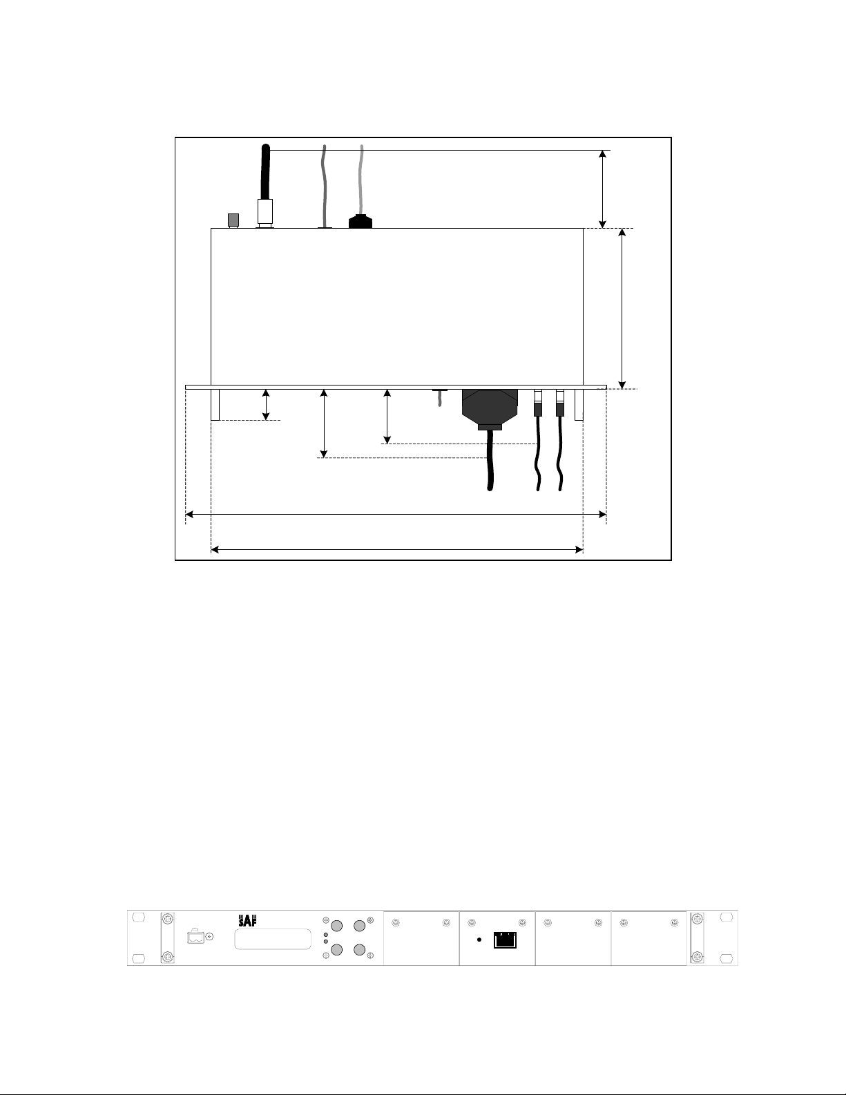
2 Fast Ethernet Bridge IDU Appearance
The modular Ethernet bridge IDU is implemented as 19” rack mountable aluminium
1U high unit; the depth of the unit is 230 mm without front panel handles and 270
mm with handles.
12 cm
(4.72 ")
23 cm
(9.10 ")
4 cm
(1.57 ")
10 cm
(3.94 ")
8 cm
(3.15 ")
Eth
(19.29 ")48.6 cm
(16.93 ")42.6 cm
V.35 E1
A maximum of 350 mm deep rack is required for the IDU to be mounted, from
mounting points of front panel, including space behind the unit for cables to RF,
Grounding point, Ethernet and Serial management interfaces. Some space is
required in front of the IDU for traffic interface cables, roughly 10 cm are needed for
V.35 interface port connector, 8 cm for E1 BNC port connectors.
The CFM-34-REBM IDU contains:
- Multiplexer board;
- Ethernet bridge board (provides the primary 100Base-Tx Ethernet interface);
- Interface module(s) (optional)
- Management controller board;
- IDU-ODU Cable interface;
- Baseband modem;
- Power Supply module;
- LCD and Keypad modules.
All the aforementioned boards and modules are interconnected with flat ribbon
cables and snap-on connectors.
CFM-8-REBM
CLEAR
SL
ENTER
RA
100M
LAN
Slot 3 Slot 4
Figure 1. Modular Ethernet bridge front panel (with no modules installed)
Modular Fast Ethernet Bridge Management System Technical Description and Configuration Guide
V. 3.12. 1.0 · © SAF Tehnika A/S 2003
4
Page 5

5
The CFM-34-REBM IDU provides:
- Interfaces to:
- Radio outdoor Unit (ODU), N-type female connector;
- 100Base-Tx Ethernet LAN port, for connection to LANs;
- RS-232 serial management port;
- 10Base-T Ethernet management port;
- LCD display and corresponding keypad buttons to control LCD;
- LAN activity LEDs (speed, link integrity);
- Power connector;
- Reset button;
- DIP switch for the primary bridge configuration.
Table 1. Connectors
Front panel connectors
Connector or label Description
+-48V Power connector, IDU should be powered from 20 to 60 VDC
power source. Both “+” or “–“ poles of the power source could be
grounded, one should make sure if the chosen grounding wire is
connected to ground on the IDU power connector.
LAN 100Base-Tx Ethernet port (primary), shielded RJ-45 connector;
Interface module port
Please refer to Chapter 3.
connectors
Rear panel connectors
Connector or label Description
RF (N-type
connector)
Radio Unit port; Use 50 Ω coaxial cable with N-type male
connectors on both sides to connect the ODU to the IDU, such as
RG-213, LMR-400 or equivalent;
DB-9 RS232 management port for connection of ASCII console (or
analog line modem for the remote connection of ASCII console);
the RS232 console port is also used to update management
software.
RJ-45 10Base-T Ethernet management port, this port is used to connect
Telnet or Web terminal.
DB-25 Alarm port. This feature is optional.
Modular Fast Ethernet Bridge Management System Technical Description and Configuration Guide
V. 3.12. 1.0 · © SAF Tehnika A/S 2003
Page 6

Table 2. Front panel LEDs
Label Color Description
RA Red Radio Alarm LED indicates problems with radio unit.
The following problems cause the Radio Alarm to turn on:
− Rx signal level is lower the predefined value, - the
corresponding parameter is RxAlarmLev on the LCD or
RxAlarmLevel using Telnet/ASCII console. The default value
for this parameter is -77 dBm;
− The humidity within the radio is too high (possibly ODU is
opened);
− Transmitter malfunction (TxOut=Error)
− RF Cable=Short – cable is faulty, RF Cable=Off – cable or
Radio is faulty;
− Tx and Rx syntheser loops are not locked (TxPLL=Error,
RxPLL=Error)
If not lit – operating properly (Rx=OK & TxOut=OK &
Humidity=Low & RF Cable – OK & TxPLL=OK & RxPLL=OK);
The RA LED will also switch on if the Radio loopback is active
and/or if the transmitter power is switched off.
The RA LED is updated one time per second.
SL Red
Red Sync Lost LED indicates the multiplexer has lost
synchronization;
If not lit – operating properly;
The SL LED is updated one time per second.
100M Green Indicates LAN port speed: ON – 100 Mbps, OFF – 10 Mbps
connector
Green
(right)
Indicates good LAN link integrity LAN port
LEDs
Yellow
LAN receiving data
(left)
Modular Fast Ethernet Bridge Management System Technical Description and Configuration Guide
V. 3.12. 1.0 · © SAF Tehnika A/S 2003
6
Page 7
7
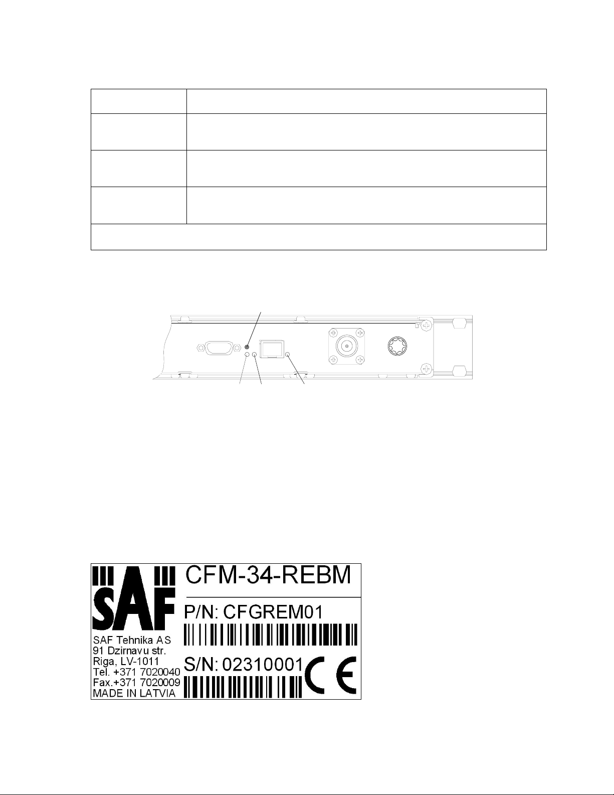
Table 3. Rear side LEDs
The rear side LEDs refer to the operation of Ethernet port on the management
module board.
LED Description
A
B
C
If blinking (with a period of about 1 sec.), indicates operation of the
management module CPU;
If lit, indicates that Ethernet link is established with the
management terminal;
If blinking, indicates data interchange between the IDU and the
management terminal;
Note: A, B and C correspondence to LEDs is shown in the figure below.
Hidden reset
button
AB C
Figure 2. CFM-34 Remote Fast Ethernet Bridge rear side panel LEDs
For more information on Reset button please refer to the section 4.2.3.
2.1 Labelling
The IDU label is found at the rear panel;
P/N – product number, the last two numbers denote the product version;
S/N – serial number.
The combination of product number and serial number uniquely identifies each unit.
Figure 3. Label of the CFM-34-REBM IDU
Modular Fast Ethernet Bridge Management System Technical Description and Configuration Guide
V. 3.12. 1.0 · © SAF Tehnika A/S 2003
Page 8
3 Interface modules
3.1 V.35 Interface Module
V.35 interface module is provided with M34 standard connector. In the modular
Ethernet bridge the V.35 module terminates 2 Mbps from Mux and provides user
selectable data rates of 64 kbps, 128 kbps, 256 kbps, 512 kbps, 1024 kbps and
2048 kbps to single V.35 interface on M.34 connector.
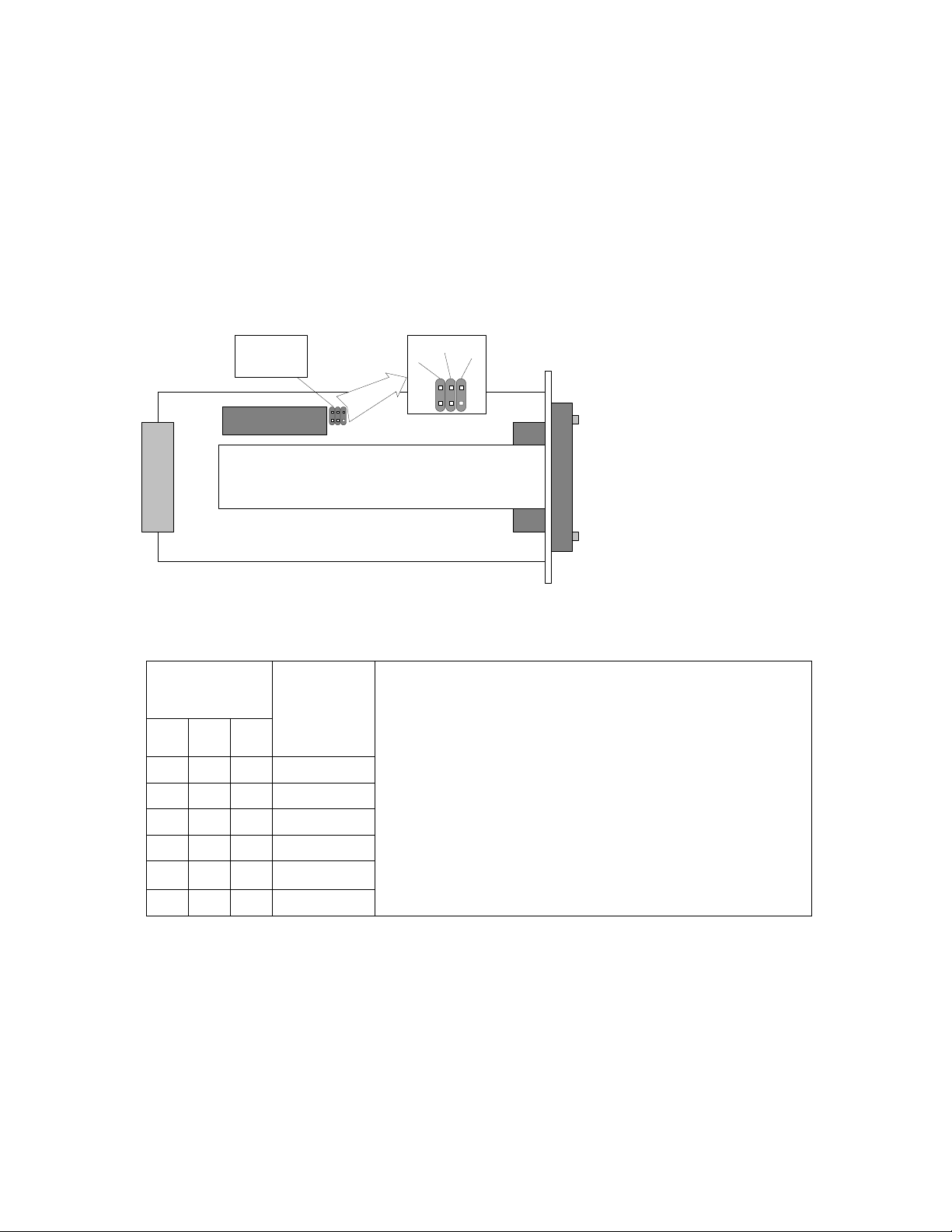
3.1.1 Configuring V.35 Module
The V.35 interface module has three jumpers on the board. These jumpers are used
for adjusting the capacity.
jumpers for
configuration
of capacity
V.35 vers. 2
B
A
C
V.35 interface module
The adjustments should be done in accordance with the table below.
Jumper
layout
Capacity,
[kbps]
A B C
2048
1024
512
256
Notes:
• A, B and C jumpers are depicted in the figure
above (on the right);
• - conjuncted jumper;
• For rates under 2 Mbps, the corresponding
multiplexer slot should be configured on 2 Mbps;
• * - Can be set from Telnet or ASCII console only;
• The software setting has a priority over the
jumper setting, i.e. if the software settings were
made, jumper setting is overrided.
128
64
The capacity can also be adjusted from IDU LCD or through the Telnet or ASCII
management terminal:
• From Telnet/ASCII terminal use the command line: “Mod # setv35 speed <speed
in kbps>”, see also Chapter 4.4.3 for details.
• From IDU LCD: Press “ENTER” to enter setup mode → select “Modules” → select
“Module # V35” → select “V.35 Speed” → “Change Speed”, choose the capacity
and confirm as prompted.
The special installation and configuration guide is available for V.35 Interface
module, which has a review of parameters and describes how to configure them, see
Refer for details.
Modular Fast Ethernet Bridge Management System Technical Description and Configuration Guide
V. 3.12. 1.0 · © SAF Tehnika A/S 2003
8
Page 9

3.1.2 V.35 Interface Module LEDs
There are four LEDs on V.35 module. LEDs have a multifunctional meaning, basic
meanings are:
• C (DCD) - data carrier detected
• D (Data, both TxD and RxD)
• S (Send, both RTS - Request to Send, CTS - Clear to Send)
• R (Ready, both DSR - Data Set Ready, DTR - Data Terminal Ready)
General color meaning:
Green – normal operation; Yellow – information for service modes;
Red – fault indication; Not lit – no signal; Flickering – additional information.
Table 4. V.35 interface module LEDs
LED Description
C (DCD)
D (RxD,
TxD)
S (RTS,
CTS)
R (DSR,
DTR)
Green – carrier is detected;
Red – carrier is NOT detected, (problem with radio)
The following will be available through management facilities:
Flickering yellow and green(7:1) – loopback is set and carrier is
detected;
Flickering yellow and red(7:1) – loopback is set and carrier is NOT
detected;
Flickering yellow (7:1) – loopback is set and cable is damaged;
Flickering green (7:1) – cable is damaged and loopback is NOT set;
Green – both received and transmitted data signals are OK,
Off – none is present,
Green is blinking and goes off – just one data signal is present
(TxD:RxD = 7:1),
Yellow – remote loopback is set;
Green – both signals are active,
Off – both signals are inactive,
Flickering green – one control signal is present, another is absent
(RTS:CTS = 7:1),
Blinks yellow and red – module has set the CTS signal but the
returned signal is dissimilar to that set by the module, - indicates cable
fault;
Green – both signals are active,
Off – both signals are inactive,
Flickering green – one control signal is present, another is absent
(DSR:DTR = 7:1),
Blinks yellow and red – module has set the DSR signal but the
returned signal is dissimilar to that set by the module, - indicates cable
fault.
Modular Fast Ethernet Bridge Management System Technical Description and Configuration Guide
V. 3.12. 1.0 · © SAF Tehnika A/S 2003
9
Page 10

3.2 E1 Interface Module
The E1 interface module is a single port module provided with two types of
interfaces:
• 120 Ω balanced interface, accessible through RJ-45 type connector,
• 75 Ω unbalanced interface, requires a pair of coaxial cables with the BNC type
connector.
Both interfaces are provided for termination of 2 Mbps (G.703) streams.
Table 5. E1 Interface module connectors
Out,
In
RJ-45 RJ-45 connector for balanced E1 interface.
Table 6. E1 interface module LEDs
Label Color Description
Tx Green Steady green light indicates the E1 module is ready to transmit data
Rx Green Steady green light indicates the data signal from E1 input.
AIS Red Steady red LED indicates the AIS signal from E1 input.
LB Red “LoopBack” LED (red) indicates loopback mode is activated in the
Two BNC connectors provide means to connect the CPE equipment to the IDU;
Tx data stream is transmitted over OUT (output) port;
Rx data is to be received through IN (input) port.
to CPE connected to E1 port.
In case if Multiplexer synchronization is lost (S.L. LED is lit), Tx LED
goes off and AIS signal is transmitted from E1 port to CPE.
module.
3.2.1 Configuring E1 Interface Module
The switching between balanced/unbalanced interfaces is available from
LCD/Keypad, Telnet, ASCII and Web terminals:
• From Telnet or ASCII console it can be accomplished using “Mod # setE1
{120|75}” command line, see Chapter 4.4.3.
• From IDU LCD: Press “ENTER” to enter setup mode → select “Modules” → select
“Module # E1” → select “E1 Interface” → “Ch. Interface”, choose the interface
and confirm as prompted.
Modular Fast Ethernet Bridge Management System Technical Description and Configuration Guide
V. 3.12. 1.0 · © SAF Tehnika A/S 2003
10
Page 11
3.3 REB Interface Module
The CFM series REB interface module features a complete filtering Ethernet bridge.
The REB module terminates any capacity of 2-4-6-8 Mbps from the multiplexer on a
single 10 Mbps 10Base-T UTP Ethernet port.
REB Interface Module LEDs
There are two groups of LEDs on the front of the module:
• LAN: Rx, Tx
• WAN: Rx, Tx
Green color of the LED indicates activity.
Red color of the LAN Tx LED indicates the absence of the LAN link signal on the
Ethernet.
Red color of the LAN Rx LED indicates LAN collision in case if Ethernet port of the
REB module operates in Half Duplex mode.
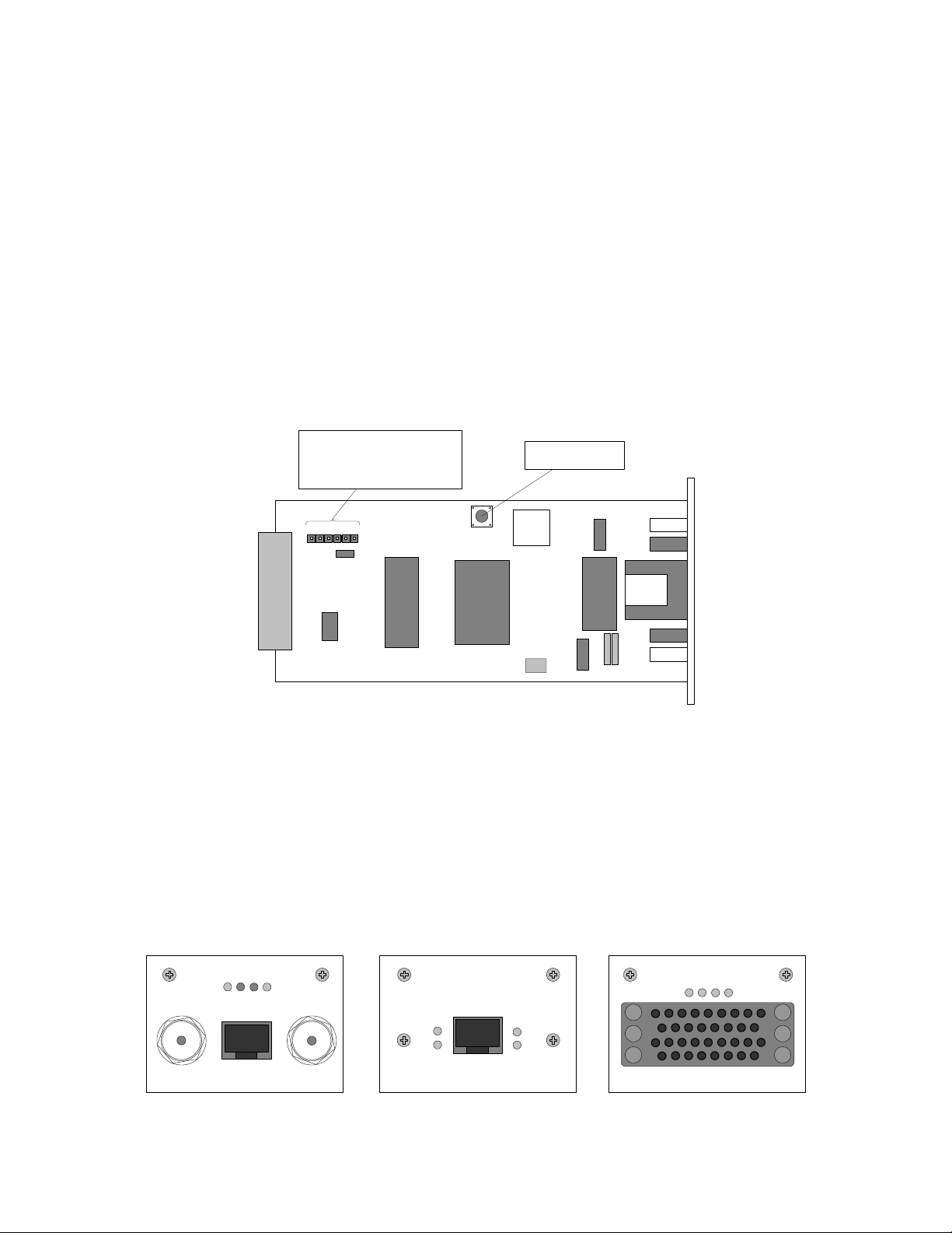
The REB module has a connector and a jumper onboard marked with “JMP” and the
reset button to restart the Ethernet bridge.
Jumper and Connector
for production use only
Reset button
(not configurable)
JMP
Figure 3.1. The remote Ethernet bridge module
The reset button may useful for testing purposes.
Both the jumper and the connector are used for production and are not configurable.
The switching between Fdx and Hdx port modes can be accomplished as follows:
• From Telnet or ASCII terminal it can be accomplished using “Mod # setbridge
{Hdx|Fdx}” command line (Chapter 4.4.3).
• From IDU LCD: Press “ENTER” to enter setup mode → select “Modules” → select
“Module # Bridge” → select “Bridge Interface” → “Change FDX/HDX”, choose the
mode and confirm as prompted
LB
TX
RX
AIS
OUT IN
E1
LAN
RX
TX TX
REB
WAN
RX
CD
V.35
R
S
The front view of the interface modules: E1, REB, V.35
Modular Fast Ethernet Bridge Management System Technical Description and Configuration Guide
V. 3.12. 1.0 · © SAF Tehnika A/S 2003
11
Page 12

4 Management Interfaces
4.1 Reading the LEDs
Refer to Chapter 2 (Table 2) and Chapter 3.
4.2 LCD/Keypad
LCD display and keypad provides most basic method to locally configure and monitor
the local CFM terminal (IDU + ODU).
The LCD is constantly backlit and is able to display 2 lines of 16 symbols each line.
The LCD operates in two modes, Status display and Setup mode, please refer to
Flow Chart 1, page 43.
Keypad consists of 4 buttons:
ENTER is used to confirm the choice of displayed item or entered data as
well as to switch from status display to setup mode.
CLEAR is used to cancel the choice or to move to previous menu level.
↑ ↓ Up/Down buttons are used:
- To switch between options for menu items displayed;
- To choose parameter to set up and to set its value.
4.2.1 “Status Display” Mode of the IDU LCD Management Interface
Once the IDU is powered up, it automatically enters “Status Display” mode,
displaying two parameters at a time statically (use up/down buttons to scroll through
parameters). These parameters are listed in the Table 7.
Table 7
Parameter Values and description
Tx=23362.5MHz Parameter indicates Tx frequency of the Radio.
Rx=22354.5MHz Parameter indicates Rx frequency of the Radio.
TxPower=+20dBm Parameter indicates Tx power of the Radio.
Rx= OK
Cable=–5 dB
Rx parameter indicates various states of IDU receiver and ODU:
“OK” indicates the IDU receives acceptable signal from ODU;
“Low” indicates the received signal level is too low for the IDU to
operate properly;
“Error” indicates some internal fault in the ODU receiver, please
contact sales representative or manufacturer.
Parameter indicates signal attenuation in ODU-IDU cable, values
of 0 … -20 dB provide proper operation of IDU.
Modular Fast Ethernet Bridge Management System Technical Description and Configuration Guide
V. 3.12. 1.0 · © SAF Tehnika A/S 2003
12
Page 13

RxLev= -66dBm
Parameter RxLev indicates the level of the received signal,
values from –40 dBm to –90 dBm provide proper operation of
the system.
TxOut=Ok
Parameter indicates operation status of ODU transmitter:
“Ok” indicates proper operation;
“Error” indicates internal fault in ODU transmitter, please
contact sales representative or manufacturer.
TxPLL=Ok
Parameter indicates operation status of ODU Tx Syntheser Loop
(PLL lock):
“Ok” indicates proper operation;
“Error” indicates internal fault in ODU transmitter, please
contact sales representative or manufacturer.
RxPLL=Ok
Parameter indicates operation status of ODU Rx Syntheser Loop
(PLL lock):
“Ok” indicates proper operation;
“Error” indicates internal fault in ODU receiver, please contact
sales representative or manufacturer.
t= 23C Indicates ODU internal temperature
Humidity=Low Parameter indicates humidity level inside ODU,
“Low” indicates acceptable moisture levels;
“High” indicates too high level of humidity, condensing.
Restart= 3
Parameter indicates number of ODU management controller
restarts since counter was reset.
IDU t= 31C Parameter indicates internal temperature inside IDU
LAN= Half Duplex
Parameter indicates the primary Ethernet port mode: "Eth=Half
Duplex" or "Eth= Full Duplex".
LAN link= OFF Indicates Ethernet LAN link integrity
LAN speed= 10M Indicates the primary Ethernet port speed: 10M or 100M
RF Cable – OFF
Parameter indicates power consumption of the ODU:
“OK” indicates acceptable level;
“Short” indicates short circuit in cable;
“Off” indicates too low power consumption by ODU. This is most
likely due to the brake in the cable. If the cable is intact, the
ODU is faulty (contact your SAF Tehnika sales representative).
MUX
0M+34M+0M+0M
RxAlarmLev =-71
Indicates the current MUX slot speed configuration (see chapter
4.2.2 for details).
Indicates the Rx level (in dBm) at which the Radio Alarm is
switched on (parameter adjustable from Telnet/ASCII console).
UpTime=5371 Indicates the system up-time in seconds.
DownTime=4 Indicates the system down-time (SL alarm on) in seconds.
FrmErr=23
Indicates the count of frames received from the WAN that has
error(s) within the time interval equal to the sum of uptime and
downtime counters.
BBLoopback=OFF Indicates if the base-band loopback is switched on or off.
Modular Fast Ethernet Bridge Management System Technical Description and Configuration Guide
V. 3.12. 1.0 · © SAF Tehnika A/S 2003
13
Page 14
4.2.2 “Setup” Mode of the IDU LCD Management Interface
Following table describes parameters available for change by the CFM-34-REBM
Indoor Unit in “Setup” mode.
Algorithm of LCD operation is shown on Flow Chart 1, page 43.
Table 8
Parameter Values and description
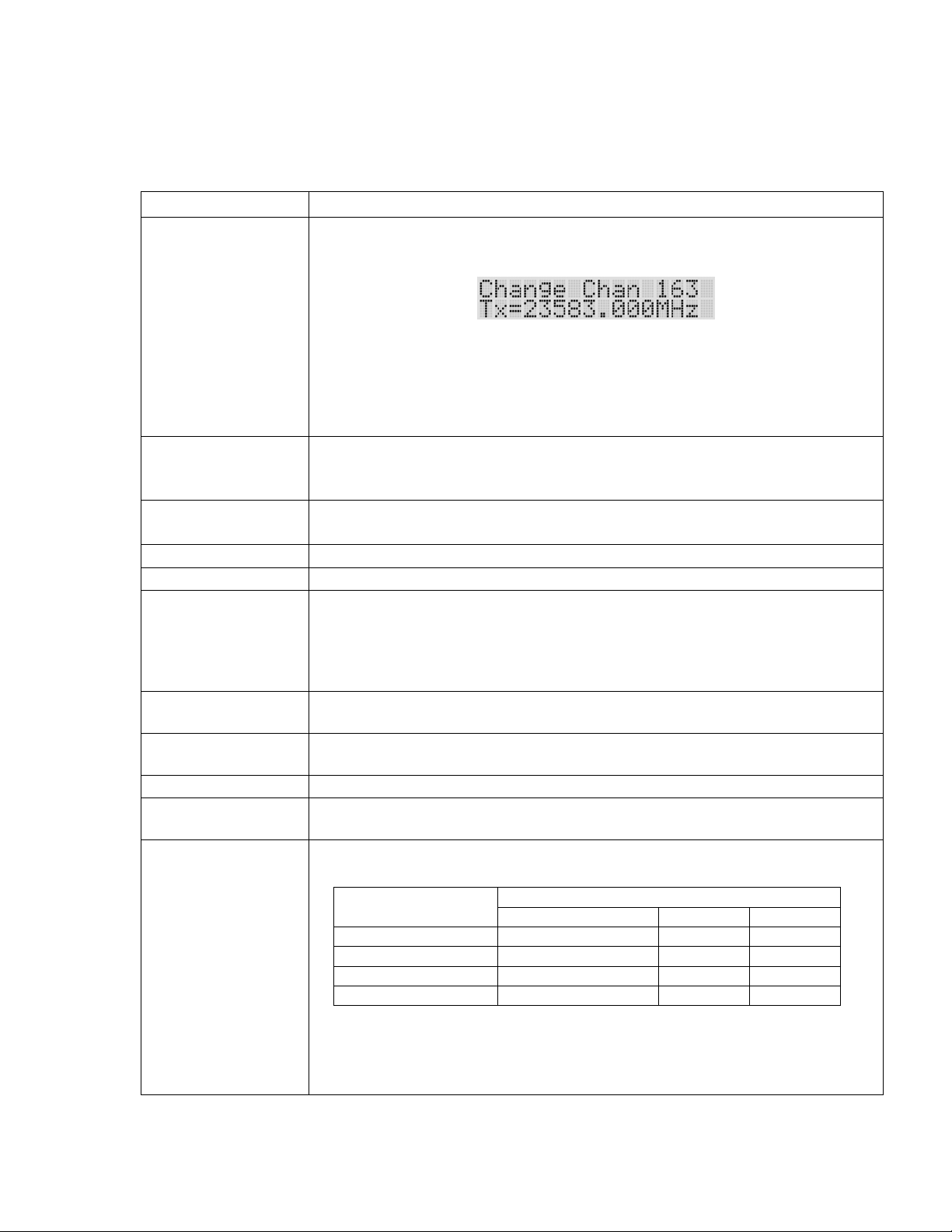
Change Chan ##
Tx Power +5dBm “TxPower” parameter sets the ODU Transmitter power rate.
Select IP Default value - 192.168.205.010 or 192.168.206.010
Select NETMASK Default value – 255.255.255.000
Select Gateway Default value – 255.255.255.255 (No gateway specified)
Access Code
Reset counters
RF loopback OFF Turns the RF loopback (Radio loopback) on or off.
BB loopback ON
“Change Chan” item provides ODU Tx and Rx frequency setup
functionality:
If this item is chosen LCD shows, for example:
where “163” – number of currently used Tx channel and “Tx” frequency appropriate to channel.
Channel numbers and corresponding Tx, Rx frequency values are
listed in tables in Chapter 8, page 52.
Operator sets desired channel number scrolling through values with
“Up” or “Down” buttons and confirming the choice with “Enter” button.
The default setting is “OFF”, allowing safe deployment of the
equipment avoiding interference risk with other radio equipment.
Important!: Do not enter address “255.255.255.255”
IP (IP address), Netmask and Gateway parameters provide the
means of addressing management board of IDU in order to control
and manage IDU locally and monitor ODU both locally and remotely.
Note: It is necessary to restart the management CPU for any changes
in IP settings (including SNMP terminal IP settings) to take effect.
Specify the panel access code (a number from 0 – 200) to enable any
adjustments from IDU.
Resets up-time, down-time and Frame error counter, see page 30 for
details.
Turns the baseband loopback on/off (BB loop analog – analog base-
band loop, BB loopback on – digital base-band loopback).
MUX speeds
Sets the data rate for multiplexer slots (for slot numbering see Figure
1); the following configurations are available:
Designation
Primary Ethernet Slot 3 Slot 4
Data rate
0M+34M+0M+0M 34 Mbps 0 Mbps 0 Mbps
0M+30M+2M+2M 30 Mbps 2 Mbps 2 Mbps
0M+32M+0M+2M 32 Mbps 0 Mbps 2 Mbps
0M+32M+2M+0M 32 Mbps 2 Mbps 0 Mbps
The numbering of slots is shown in Chapter 2.
Note: if no additional interface modules are used, the multiplexer
should be configured as [0M+34M+0M+0M] to ensure maximum
capacity (34 Mbps) of the primary Ethernet interface.
continued on next page
Modular Fast Ethernet Bridge Management System Technical Description and Configuration Guide
V. 3.12. 1.0 · © SAF Tehnika A/S 2003
14
Page 15
5
continued from previous page
Write config Saves all settings in EPROM of the management controller.
Restart CPU
Restarts management CPU for the new IP settings to take effect.
Resets all management counters.
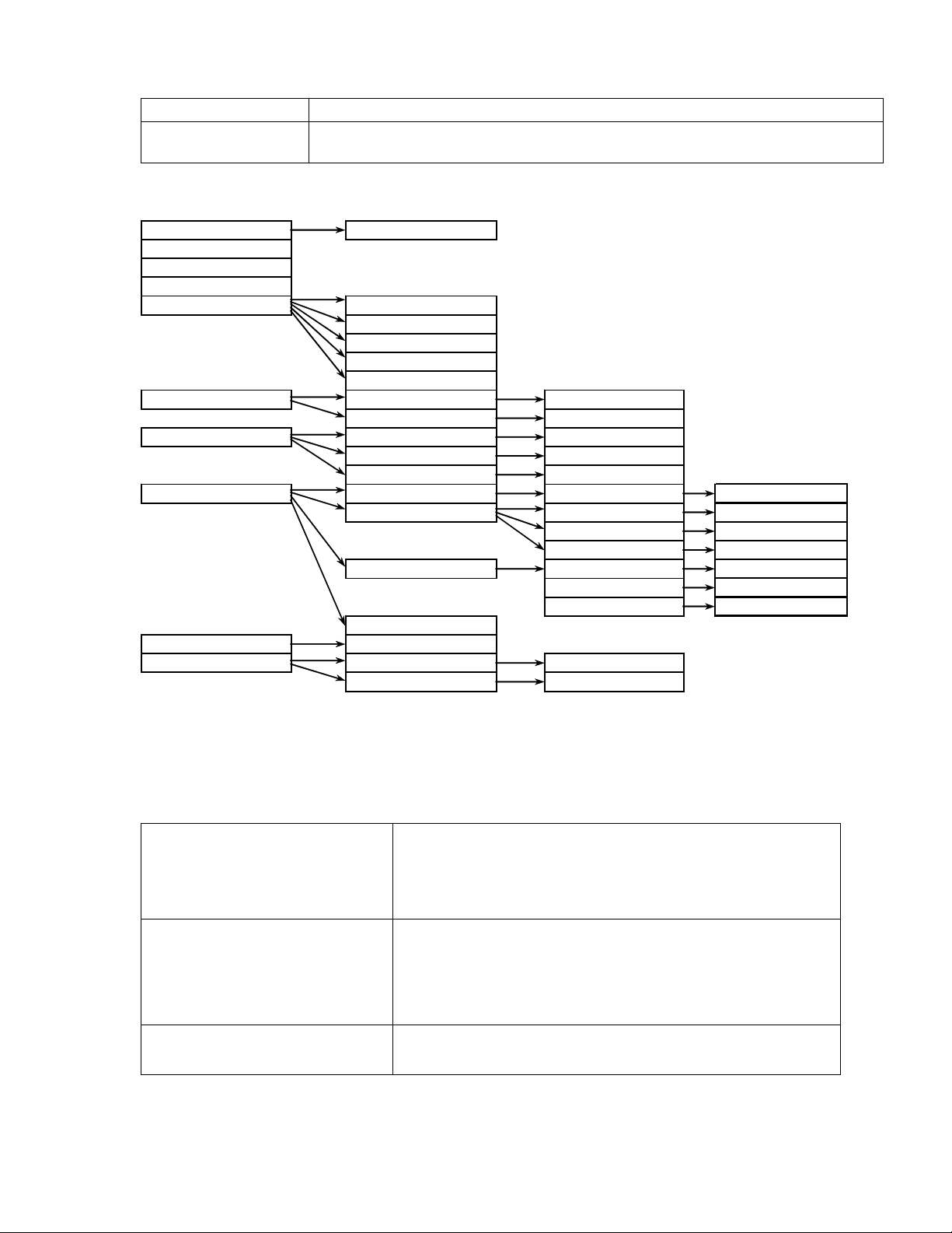
Setup mode menu tree
Access code Change * - current channel number
Restart CPU ** - multiplexer slot number
Reset Counters *** - Dloop - Digital loopback
Write Config **** - Aloop - Analog loopback
Loopbacks RF loopback ON
RF loopback OFF
BB loopback ON
BB loop analog
BB loopback OFF
Outdoor unit Chan ##* Change Chan ##
Power Tx Power
Ethernet Select IP Change
Select NETMASK Change
Select Gateway Change
Modules Module #** Bridge Bridge interface Change FDX/HDX
Module # E1 E1 Interface Ch. Interface
E1 Dloop*** Change Dloop
E1 Aloop**** Change Aloop
Module # V35 V.35 Speed Change Speed
V.35 Loopback Change Loopback
V.35 Clock Change Mode
Module # N/A
MUX Speeds Change
Service line Select local IP Change
Select remote IP Change
4.2.3 Reset Functions
Depending on the method used, the user may reset the whole terminal (IDU+ODU)
or the management controller individually, see table below for details.
Reset through the LCD menu
system using “Restart CPU”
option or from the
Telnet/ASCII console using
“restartcpu” command
Reset action using hidden
button at the rear side of the
IDU (see Figure 2)
Unplugging of power supply Restarts the multiplexer module and the management
Modular Fast Ethernet Bridge Management System Technical Description and Configuration Guide
V. 3.12. 1.0 · © SAF Tehnika A/S 2003
Restarts the management module. Resets all
management counters.
Restarts both the multiplexer module and the
management module. Resets all management
counters.
Note: This may require a pin, at least 15 mm long,
approx. 1.5 mm in diameter.
module. Resets all management counters.
1
Page 16
4.3 RS-232 Serial Management Port
RS-232 serial management port of the IDU will provide terminal management via
connected PC or other terminal or modem.
In order to interconnect the IDU and the management terminal directly through
serial ports, a straight through modem cable is needed. The serial port of the
management terminal should be configured as 19200 8-N-1, no data flow control.
IDU
IDU
RS-232
RS-232
Modem
PC/Terminal
Modem
PC/Terminal
If using modems, the management terminal is connected with the IDU remotely
through a telephone line. In this case the modem, which is connected with the IDU,
should be configured as stated below:
- Auto answer on first ring ON
- Echo offline commands OFF
- Suppress result codes
- DTR override
The modem configuration then should be saved (typically with AT&W string).
Telnet/ASCII management console command interface
For the pin assignments of the RS232 serial port, please refer to the CFM-LM series
product family technical description. The document can be ordered from SAF Tehnika
sales representatives or downloaded from SAF Tehnika’s Web site (see Chapter 8).
Modular Fast Ethernet Bridge Management System Technical Description and Configuration Guide
V. 3.12. 1.0 · © SAF Tehnika A/S 2003
16
Page 17
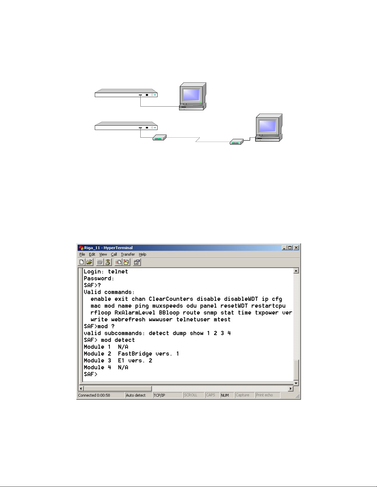
7
In order to connect the PC to the RS232 management port using Hyper Terminal
program (this program is included in any Windows version), proceed as described
below.
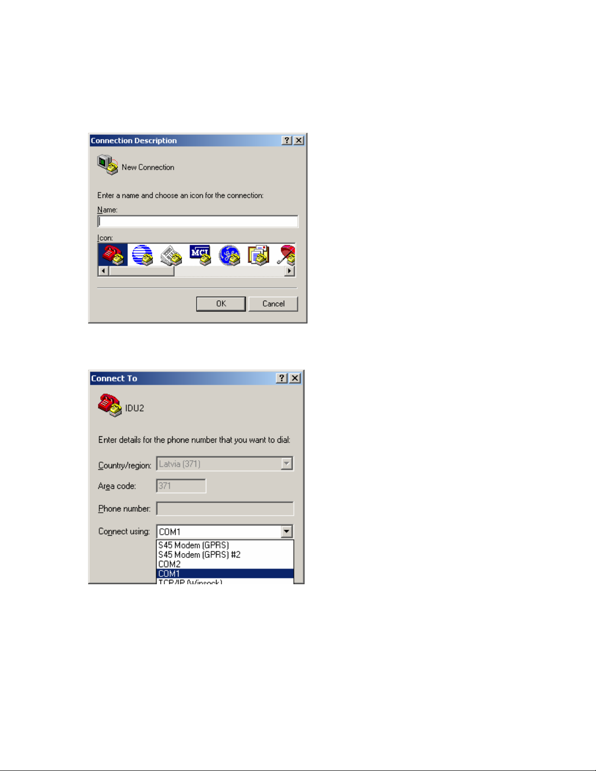
1. Connect PC to the RS232 serial port by means of “straight through” or modem
serial cable (null-cable).
2. Run “Hyper Terminal” program.
3. Make a New connection, enter connection name.
4. Choose port (COM1 or COM2).
Modular Fast Ethernet Bridge Management System Technical Description and Configuration Guide
V. 3.12. 1.0 · © SAF Tehnika A/S 2003
1
Page 18

5. Set port settings (bits per second: 19200, data bits: 8, parity: none, stop bits: 1,
no data flow control).
6. Press OK
7. Press Enter. Password is disabled by default.
If successfully connected, the prompt should appear as in the picture below; see
Chapter 4.4.3 for available commands.
Modular Fast Ethernet Bridge Management System Technical Description and Configuration Guide
V. 3.12. 1.0 · © SAF Tehnika A/S 2003
18
Page 19

4.4 Ethernet Management Port
Ethernet port of the CFM-34-REBM IDU terminal is intended as main source of
management connectivity and will provide the broadest range of management
functionality:
- Web management via integrated Web server of management board;
- SNMP management via integrated SNMP agent of management board;
- Telnet server and CLI interface.
Ethernet interface could be used:
- To connect IDU to PC/Laptop to manage IDU;
- To LAN for constant monitoring of IDU;
- To router or any other TCP/IP packet network termination unit to have IDU as
part of network for management information.
4.4.1 Web Interface
The implementation of Web interface for the CFM-34-REBM IDU provides monitoring
and configuration capabilities similar to ones available from the IDU LCD/Keypad,
front panel LEDs, and from the Telnet/ASCII console, for details please refer to
Chapters 4.2.1, 4.2.2, and 4.4.3.
The Web interface functionality is available via the Ethernet management
port only.
Web interface is accessible by any standards based Web browser.
The CFM-34-REBM IDU Main Web management window: it shows the Radio
characteristics, main system settings, and alarm status. Entries, which are
highlighted in red, indicate that specific parameters do not comply with the norms of
normal operation, all other parameters are satisfactory
Modular Fast Ethernet Bridge Management System Technical Description and Configuration Guide
V. 3.12. 1.0 · © SAF Tehnika A/S 2003
19
Page 20

To check the status of each module, click on a Module Status link to open the
module status window.
The CFM-34-REBM Module Status window
When clicked on the link of any of the configuration windows for the first time since
the main Web page was opened, you will be prompted to enter User Name and
Password. The default username is SAF (in capital letters) and the default password
is test.
There are two configuration windows, - the Main Configuration window and the
Module Configuration window.
The following operations can be performed from the Main Configuration window:
− restart the system,
− save the current configuration,
− change MUX slot speeds,
− change the Web page refresh time.
Modular Fast Ethernet Bridge Management System Technical Description and Configuration Guide
V. 3.12. 1.0 · © SAF Tehnika A/S 2003
20
Page 21

Main Configuration window (not extended for Radio parameters)
The configuration of modules (including loopbacks) is available from the Modules
Configuration window.
The CFM-34-REBM IDU Module Configuration Web management window
Modular Fast Ethernet Bridge Management System Technical Description and Configuration Guide
V. 3.12. 1.0 · © SAF Tehnika A/S 2003
21
Page 22

4.4.2 SNMP Interface
In order to receive SNMP traps from the IDU management controller, the IP address
of the management PC with the installed Trap Manager software (based on SNMP
platform) should be specified from a Telnet or ASCII console.
The IP address of the SNMP Trap Manager can be specified using the “SNMP trap
<IPaddress>” command. The default value is 255.255.255.255 (no SNMP Trap
Manager specified).
The Trap Manager address should be configured for each IDU, from which it is
necessary to receive information on parameters, counters and alarms. The
information is sent as SNMP Trap packets through the mediation of UDP protocol. If
the Trap Manager terminal cannot be accessed, - for example, if there is no device
connected to the Ethernet management port or IP settings of the management port
are improper, a longer delay (about 10 sec.) may appear on the IDU startup.
SNMP management functionality is available from any SNMP browser, by means of
compiling SAF MIB to browser’s MIB base.
SAF MIB is available from:
- SAF Tehnika Web site, www.saftehnika.com;
- From SAF Tehnika tech support, email: techsupport@saftehnika.com;
- Contacting SAF Tehnika or distributors.
Here is the sample of SNMP query of the CFM-34-REBM IDU
***** SNMP QUERY STARTED *****
sysDescr.0 (octets) SAF SNMP and WWW management
sysObjectID.0 (oid) saf
sysUpTime.0 (timeticks) 0 days 00h:33m:34s.90th (201490)
productType.0 (int32) cfm-16(2)
productDescr.0 (octets) SAF CFM-34-REBM
description.0 (octets) SAF 23GHz microwave radio
version.0 (octets) V2.16 2000.09.05
radioAlarm.0 (int32) on(1)
signalAlarm.0 (int32) none(0)
v_01.0 (octets) Tx=23362.5MHz
v_02.0 (octets) Rx=22354.5MHz
v_03.0 (octets) TxPower=+20dBm
v_04.0 (octets) RxLev=-109dBm
v_05.0 (octets) Cable=- 26dB
v_06.0 (octets) TxOut=Ok
v_07.0 (octets) TxPLL=Ok
v_08.0 (octets) RxPLL=Ok
v_09.0 (octets) t= 23C
v_10.0 (octets) Humidity=Low
v_11.0 (octets) Restart= 7
v_12.0 (octets) IDU t= 27C
v_13.0 (octets) RF Cable - OFF
v_14.0 (octets) MUX 0M+34M+0M+0M
***** SNMP QUERY FINISHED *****
Sample of SNMP query of the CFM-34-REBM IDU
Modular Fast Ethernet Bridge Management System Technical Description and Configuration Guide
V. 3.12. 1.0 · © SAF Tehnika A/S 2003
22
Page 23

The following table describes all variables defined in the MIB.
Variable Name Variable
Value List Description
Type
termProduct String Textual name of terminal type
termDescription String Textual description of terminal
termLocation String IDU name
termVersion String Textual version of management
termOperation Integer (32 bit) none(0)
booting(1)
ok(2)
testing(3)
error(4)
termIduTemperature Integer (32 bit) Temperature within IDU
termRfCablePowerStatus Integer (32 bit) off(0)
ok(1)
short(2)
error(3)
termUpTime Integer (32 bit) System up-time in seconds
termDownTime Integer (32 bit) System down-time in seconds
bbVersion String Textual version of the Base-band
bbOperation Integer (32 bit) none(0)
booting(1)
ok(2)
testing(3)
loopback(4)
illegalSpeed(5)
error(6)
bbLinkCapacity Integer (32 bit) Base-band link capacity in Kbps
bbLinkCapacityDescription String Comment on Base-band link
bbLoopback Integer (32 bit) off(0)
digital(1)
analog(2)
bridgeLanLinkLostAlarm Integer (32 bit) none(0)
on(1)
rfOperation Integer (32 bit) none(0)
booting(1)
ok(2)
testing(3)
error(4)
noDataFromODU
(5)
rfAlarm Integer (32 bit) none(0)
on(1)
rfVersion String Textual version of the Radio
rfSide Integer (32 bit) low(0)
high(1)
rfChannel Integer (32 bit) Channel number
rfTxFrequency String Tx frequency
rfRxFrequency String Rx frequency
rfTxPower Integer (32 bit) Transmitter power
rfRxState Integer (32 bit) low(0)
ok(1)
error(2)
loopback(3)
rfRxLevel Integer (32 bit) Received signal level [dBm]
rfCableAttenuation Integer (32 bit) Signal attenuation in ODU-IDU cable
software
Terminal (IDU) operational status:
none – not initialized;
testing, illegalSpeed, error –
reserved
(range: -128..127)
Indicates power consumption of the
ODU: ok - acceptable level,
short - short circuit in cable,
off - too low power consumption,
error – internal fault
controller software
Operational status of the Base-band
modem:
none – not initialized
loopback – Base-band loop is set on
testing, illegalSpeed, error –
reserved
Base-band loopback
Link integrity on the Ethernet data
port (UTP),
none – normal operation
on – link lost
Operational status of the Radio:
none – not initialized
testing, error – reserved
noDataFromODU – no data is being
received from ODU
Radio Alarm, none – off
Band side of the Radio: low or high
Reception status:
low – Rx signal level
ok - normal
error - internal fault in the Radio
loopback – RF loop is set on
(0…-20 db - proper operation)
Modular Fast Ethernet Bridge Management System Technical Description and Configuration Guide
V. 3.12. 1.0 · © SAF Tehnika A/S 2003
23
Page 24

rfTxOut Integer (32 bit) error(0)
ok(1)
off(2)
rfTxPLL Integer (32 bit) error(0)
ok(1)
rfRxPLL Integer (32 bit) error(0)
ok(1)
rfOduTemperature Integer (32 bit) Internal temperature of ODU (0C)
rfOduHumidity Integer (32 bit) low(0)
high(1)
rfLoopback Integer (32 bit) off(0)
on(1)
rfRxAlarmLevel Integer (32 bit) Rx level (in dBm) at which the Radio
brDescription String Textual description of the Bridge
brVersion String Textual version of the Bridge
brOperation Integer (32 bit) none(0)
booting(1)
ok(2)
testing(3)
loopback(4)
illegalSpeed(5)
error(6)
brLanMode Integer (32 bit) other(0)
halfDuplex(1)
fullDuplex(2)
brLanSpeed Integer (32 bit) LAN speed
brLanLinkState Integer (32 bit) other(0)
linkOK(1)
linkLOS(2)
*m3Type error(0)
e1(33)
v35(37)
bridge(43)
none(255)
m3Description String Description of the module
m3Version String Textual version of the module
m3Speed Integer (32 bit) Module data transfer speed in kbps
m3Operation Integer (32 bit) none(0)
ok(2)
loopback(4)
illegalSpeed(5)
m3Rx Integer (32 bit) none(0)
ok(1)
noSignal(2)
noLink(3)
rxAIS(4)
m3Tx Integer (32 bit) none(0)
ok(1)
noSignal(2)
txAIS(4)
m3Loopback Integer (32 bit) off(0)
on(1)
analog(2)
Operation status of the ODU
transmitter:
ok – proper operation
error – internal fault (no data from
ODU)
off – Tx power = off
Operation status of ODU Tx
syntheser loop (PLL lock):
ok – normal operation
error - internal fault in ODU
transmitter
Operation status of ODU Rx
syntheser loop (PLL lock):
ok – normal operation
error - internal fault in ODU
transmitter
Humidity level inside ODU:
low - acceptable moisture level
RF loopback
Alarm is switched on
Oprational status of the Bridge:
none – not initialized
testing, loopback, illegalOperation,
error – reserved
LAN duplex mode:
other – not initialized;
LAN link integrity:
other – not initialized;
Module type:
error – internal fault
none – no module installed or the
module does not support data
exchange with the management
controller (e.g., due to the software)
Operational status of the module:
none – no data from the module
loopback – loopback is switched on
illegalSpeed – the speed
configuration of the MUX slot does
not mach the module speed
Rx statuss of the module:
none – not defined
noLink – for the REB module only
rxAIS – for the E1 module only
Tx statuss of the module:
none – not defined
noSignal – for V.35 module and REB
module (same as no link or LOS
alarm)
txAIS – for E1 module only (usually
switches on with the SL alarm)
Loopback in the module
Modular Fast Ethernet Bridge Management System Technical Description and Configuration Guide
V. 3.12. 1.0 · © SAF Tehnika A/S 2003
24
Page 25

5
m3RxInput Integer (32 bit) other(0)
m3TxMode Integer (32 bit) other(0)
m3TxClockSource Integer (32 bit) other(0)
m3TxClockPhase Integer (32 bit) other(0)
m3DataPolarity Integer (32 bit) other(0)
inputA (for CFM-16-8E1 and
CFM-34-16E1 IDUs only)
inputB (for CFM-16-8E1 and
CFM-34-16E1 IDUs only)
inputC (for CFM-16-8E1 and
CFM-34-16E1 IDUs only)
inputD (for CFM-16-8E1 and
CFM-34-16E1 IDUs only)
outputA (for CFM-16-8E1 and
CFM-34-16E1 IDUs only)
outputB (for CFM-16-8E1 and
CFM-34-16E1 IDUs only)
outputC (for CFM-16-8E1 and
CFM-34-16E1 IDUs only)
outputD (for CFM-16-8E1 and
CFM-34-16E1 IDUs only)
* Note:
There are more variables with the “m4” prefix in their names, they are analogical to those with the “m3”
prefix; the “m3” denotes that the parameter refers to the module in the slot 3, “m2” – module in the slot 4.
Integer (32 bit) off(0)
Integer (32 bit) off(0)
Integer (32 bit) off(0)
Integer (32 bit) off(0)
Integer (32 bit) off(0)
Integer (32 bit) off(0)
Integer (32 bit) off(0)
Integer (32 bit) off(0)
coax(1)
rj45(2)
v35(3)
halfDuplex(1)
fullDuplex(2)
master(1)
slave(2)
normal(1)
inverse(2)
normal(1)
inverse(2)
on(1)
on(1)
on(1)
on(1)
on(1)
on(1)
on(1)
on(1)
Rx input of the module:
other – not initialised
Tx mode of the module (for the REB
module only):
other – not initialised
Tx clock source of the module (for
the V.35 module only):
other – not initialised
Tx clock phase of the module (for
the V.35 module only):
other – not initialised
Polarity of the data signal (for the
V.35 module only)
other – not initialised
Input A
Input B
Input C
Input D
Power alarm (output)
Synch lost alarm (output)
Radio alarm (output)
TxPLL alarm (output)
Modular Fast Ethernet Bridge Management System Technical Description and Configuration Guide
V. 3.12. 1.0 · © SAF Tehnika A/S 2003
2
Page 26

4.4.3 Command Line Interface for Telnet/ASCII consoles
The command line management interface offers the widest configuration and
monitoring functionality. The following tables summarize all available commands for
Telnet and ASCII management terminals.
Common commands
Command Description
Time Show current date and time.
Time <YYYY-MM-DD HH:mm:ss> Set the date and time on the IDU.
Name <deviceName> Assigns a name to the IDU; The default name is “SAF”.
Write Save all settings in the EPROM. This command saves all current
settings in EPROM, including those in the script.
Ping <IPaddress> This command is for troubleshooting purposes to verify the
service channel connectivity, - sends a special packet to the
remote IDU and then waits for a reply.
BBloop {on | analog | off}
[duration]
RFloop {on | off} [duration] Set RF loopback, - “on” – set loopback, “off” – suspend
Webrefresh <refreshperiod> Refreshes the contents of WEB interface with a period specified
RxAlarmLevel Set the Rx signal level at which the Radio Alarm is switched on.
DisableWDT Reset watchdog timer (restarts management controller, resets
ResetWDT Reset watchdog timer (restarts management controller, resets
ClearCounters Reset up-time, down-time and frame error counters, see page
Exit Close Telnet session (same as to press Ctrl+D)
Disable {telnet | www | snmp |
rip}
Set baseband loopback, “on” – set digital loopback (dual),
“analog” – set analog loopback (non-dual), “off” – suspend
baseband loopback. Duration can be from 1 to 10 minutes, it is
equal to 1 min. by default.
Example: BBloop on 3
loopback. Duration can be from 1 to 10 minutes, it is equal to 1
min. by default. Example: Rfloop on 3
with refreshperiod parameter. The period is given in seconds;
the minimum period is 2 seconds.
Example: webrefresh 5 – the web page will be updated after
every 5 seconds.
The default value is –77 dBm. Example: rxalarmlevel -55
all management counters). Available from ASCII console only.
all management counters).
30 for details.
“telnet” – Disable Telnet interface
“www” – Disable Web interface
“snmp” – Disable SNMP interface
“rip” – Disable RIP
Note: after the command is entered, it is necessary to save the
configuration in EPROM (use write command) and restart the
IDU for changes to take effect.
Modular Fast Ethernet Bridge Management System Technical Description and Configuration Guide
V. 3.12. 1.0 · © SAF Tehnika A/S 2003
26
Page 27

Configuring security parameters
Command Description
Enable password <password> Specify a password to prevent unauthorized access to the
ASCII PC terminal (connected through RS232 serial port).
Panel access <accesscode> Specify a password to prevent unauthorized configuration
through the IDU management interface. The password can
be a number from 0 – 200.
WWWuser <username> <password> Specify a password (1 - 20 symbols) to prevent
unauthorized access to the Web terminal.
Telnetuser <username> <password> Specify a password (1 - 20 symbols) to prevent
unauthorized access to the Telnet terminal.
Enable rfweb {yes | <AnyString>} Enables configuration of ODU parameters (frequency, Tx
power) from the Web terminal. In order to enable it, use
“yes” with small caps; to disable use any string instead of
“yes” argument except the empty string ( “” ).
Configuring ODU parameters
Command Description
Chan <channel#> Set the ODU Tx and Rx frequency. Channel numbers
and their corresponding Tx, Rx frequency values are
listed in tables in Chapter 8, page 52.
Txpower {-10|-9|…|0|+1|+2|…|+20 |off} Set the ODU Transmitter power [dBm].
The default setting is “OFF”.
Configuring IDU parameters
Command Description
RestartCPU Restart CPU of the management controller for the new IP
settings to take effect. Resets all management counters.
Muxspeeds {0M+34M+0M+0M |
0M+30M+2M+2M |
0M+32M+0M+2M |
0M+32M+2M+0M}
Mod {3|4} stat Show parameters, - lists all parameters and input/output status
Set the speeds of the multiplexer slots, four configurations are
available (see
that refer to the specific module. Example for E1 interface
module:
SAF>mod 3 stat
Module E1 vers. 2
E1 impedance 120
TxAIS OFF
Enable Analog Loopback OFF
Enable Local Loopback OFF
Enable Remote Loopback OFF
RxAIS OFF
RxLOS OFF
Example for REB interface module:
SAF>mod 4 stat
Module Bridge vers. 1
Link ON
FDX ON
Filter ON
Figure 1 for slot numbering)
Modular Fast Ethernet Bridge Management System Technical Description and Configuration Guide
V. 3.12. 1.0 · © SAF Tehnika A/S 2003
27
Page 28

Mod {3|4} detect Detect and show current settings, - displays a list of settings of the
respective interface module. The detection procedure is carried out
each time when IDU is started up. This command is for diagnostic
purposes only.
Mod dump Show a list of modules and contents of their respective CPU registers (in
hexadecimal system). This command is for diagnostic purposes only.
Example:
SAF>mod dump
21, 02, CD, FF, 00, 00, 00, 00, 78, 00, 00, FF, 00, 01, 77, 03,
25, 01, E0, E4, E4, FF, 08, FF, FF, FF, FF, FF, FF, FF, FF, FF,
25, 02, E7, E6, E7, FF, 81, FF, FF, FF, FF, FF, FF, FF, FF, FF,
2B, 01, 00, E0, FF, 00, 00, 00, 00, 00, 00, 00, 00, 00, 00, 00,
IP addr <IPaddress> Set the IP address of Ethernet management port (requires
to restart the management module CPU).
Important!: Do not enter address “255.255.255.255”
IP mask <IPnetmask> Set the IP netmask of Ethernet management port (requires
to restart the management module CPU).
IP gw <IPaddress> Set the IP address of the default gateway to the service
channel (requires to restart the management module CPU).
IP seraddr <IPaddress> Set the IP address of the serial port of service channel for
the local (near-end) IDU management module (requires to
restart the management module CPU).
IP remaddr <IPaddress> Set the IP address of the serial port of service channel for
the remote (far-end) IDU management module (requires to
restart the management module CPU).
Route add <destinationIPaddr> Mask
[netmask] <gateway> [metric]
Route delete <destinationIPaddr>
[netmask]
SNMP community read
<communityname>
SNMP community write
<communityname>
SNMP trap <IPaddress> Set the IP address of the management terminal with the
Add a static route to the routing table. The variable
“metric” is set to 1 by default (requires to restart the
management module CPU). Example:
Route add 192.168.205.010 Mask 255.255.255.0
155.13.79.13 5
Delete a static route from the routing table (requires to
restart the management module CPU).
Specify the SNMP community name of the agent to enable
parameters to be read (not configured). The default
community name to read parameters is saf-public
Specify the community name of the agent to enable
parameters to be read and/or written (configured). The
default community name for read/write is saf-private
installed Trap Manager software, based on SNMP platform
(requires to restart the management module CPU).
Configuring E1 Interface Module parameters
Command Description
Mod {3|4} setE1 {Aloop | Dloop |
Off}
Mod {3|4} setE1 {120 | 75} Set the impedance of E1 interface, 120 Ω or 75 Ω.
Mod {3|4} setE1 TxAIS {on | off} Enable/Disable the transmission of AIS signal (for
Set the analog, digital or remote loopback in the module
(Aloop – analog loopback; Dloop – digital loopback, off –
disable current E1 module loopback).
Example: Mod 3 setE1 Dloop
configuration and testing purposes only).
Modular Fast Ethernet Bridge Management System Technical Description and Configuration Guide
V. 3.12. 1.0 · © SAF Tehnika A/S 2003
28
Page 29

Configuring V.35 Interface Module parameters
Command Description
Mod {3|4} setV35 speed {64 | 128 | 256 |
Set the speed of V.35 interface (in kbps).
512 | 1024 | 2048}
Mod {3|4} setV35 polarity {normal | inverse} Set the polarity shift of the TxC signal.
Mod {3|4} setV35 loop {on | off} Set the loopback mode of V.35 interface module.
Mod {3|4} setV35 {Master | Slave} Set the status for synchronization of V.35
interface module, ie. master or slave.
Example: Mod 3 setV35 slave
Configuring REB Interface Module parameters
Command Description
Mod {3|4} setBridge {Hdx | Fdx} Set LAN port mode of the 10Base-T Ethernet module, full
duplex or half duplex. Example: Mod 3 setbridge fdx
Verifying configuration and version
Command Description
Stat Show parameters, - lists all the parameters that are displayed in the
status display mode of the IDU LCD.
Mac Verify the MAC address of the Ethernet interface.
ODU Show version of the ODU.
Ver Show version of the IDU.
Commands for script editing
Command Description
Cfg show Show the configuration script stored in RAM.
Cfg load Load the configuration script from EPROM into RAM.
Cfg clear Clear the script stored in RAM.
Cfg delete <stringNumber> Clear a single string in the configuration script. This command is
useful for script editing.
Cfg write Save current script in EPROM. This command saves in EPROM the
current script as well as settings that are specified in it.
Syntactic notes:
− Commands are in bold font.
− All arguments (variables) are in italic font.
− Subcommands and keywords are in regular font.
− Arguments in square brackets ([ ]) are optional but required arguments are in angle brackets
(<>).
− Alternative keywords are grouped in braces ( {} ) and separated by vertical bars ( | ).
Modular Fast Ethernet Bridge Management System Technical Description and Configuration Guide
V. 3.12. 1.0 · © SAF Tehnika A/S 2003
29
Page 30

General
The management module has RAM and EPROM chips onboard. When IDU is booted
up or management module CPU is restarted, bootstrap is loaded from the EPROM
into RAM. The bootstrap contains all the parameters that was previously stored in
EPROM using write and/or cfg write commands. These parameters are stored in
EPROM in the form of script and when booting up, the script parameters are loaded
into RAM. These parameters can be freely changed thus changing the contents of
RAM. If the IDU is shut down without saving the current configuration in EPROM, the
original configuration is restored from EPROM on the next boot-up.
Here is an example of script:
SAF>cfg show
01: ip remaddr 192.168.0.11
02: ip seraddr 192.168.0.10
03: Chan 144
04: snmp community read safpub
05: snmp trap 255.255.255.255
06: route add 62.85.14.0 MASK 255.255.255.0 192.168.12.22
The script can be edited, e.g., strings can be added by simply entering the required
command (the script will be supplemented with the new string or the instant string
entry will be updated) and deleted using “cfg delete <string#>” command line. The
changes of parameters can be saved in EPROM using cfg write command line.
To end Telnet/ASCII session press Ctrl+D.
The management software has a system up-time, system down-time and frame
error timers built in. The down-time counter counts the seconds when the Signal
Lost alarm is on whereas the up-time counter returns the system up-time (in
seconds); the frame error counter counts false frames received from the WAN. All
counters are resetted using clear counters command from Telnet/ASCII terminal or
from IDU, - selecting “Reset Counters” in the setup mode.
The management module has a watchdog timer (WDT) built in which manages the
automatic restart of the management system if it freezes. Besides the restartCPU
command the management system can by resetted using restartWDT command
which breaks off check words to WDT thus causing the management system to
restart. The watchdog timer can be turned off using disableWDT command (from
Telnet/ASCII terminal) and can be turned on only by restarting the MUX and
management module using hidden reset button or unplugging power.
Radio parameters
The radio parameter values (transmit frequency and power) are stored internally in
Flash memory of the Radio unit, the Radio operates exactly with those values stored
in its Flash memory. When the radio parameter is modified during the equipment is
in operation, the corresponding radio parameter value in the Radio Flash memory is
overwritten with the new one and applied in operation. Also, each time the
equipment is booted, the radio parameter values written in the IDU bootstrap are
uploaded to the Radio and the previously stored radio parameter values in Flash
memory are overwritten with those in the IDU bootstrap. Hence the radio parameter
configuration in the IDU bootstrap has a higher priority as they will override the
values stored in the Radio on the equipment restart.
Consequently, the radio parameter configuration could be stored in the IDU
bootstrap for the purpose to be able to quickly change the Radio unit later. Normally
it is not necessary for the IDU bootstrap to contain strings that configure radio
parameters.
Modular Fast Ethernet Bridge Management System Technical Description and Configuration Guide
V. 3.12. 1.0 · © SAF Tehnika A/S 2003
30
Page 31

IDU name
The IDU name permanently appears in the prompt string of the Telnet/ASCII
terminal software, it can also be seen on the IDU LCD by pressing clear button while
in status display mode as well as on the Web browser window.
The name of the IDU can only be assigned using Telnet or ASCII terminal, this
cannot be done using IDU management interface.
The command line “Name <deviceName>” assigns a name to the IDU. The name
can be a maximum of 16 symbols long. If using space(s), the argument should be in
double quotes.
Example: Name “SAFterm2 14 7”
Security commands
For ASCII, Telnet and Web terminals only one user is supported. The default
username and password for Telnet terminal is:
− Username: telnet
− Password: saf
The default username and password for Web terminal is:
− Username: SAF
− Password: test
Take note of upper case and lower case type, it should be taken into account for
both username and password!
The passwords may contain spaces, if using space(s) the password should be
entered in quote marks.
For ASCII, Telnet and Web terminals the password can be changed simply reentering the appropriate security command while logged on. To log off press Ctrl+D,
the logging off is possible only if the password is specified. To disable password enter
the password command appropriate for the specific terminal type followed by empty
string, e.g., enable password “”.
Important!
The specification of password (or username and password) should always be
followed by saving the configuration script (using “write” or “cfg write” commands)
otherwise the password request will be ignored after the restart of CPU.
The panel access code for the access from IDU panel can be specified from the
Telnet/ASCII console only. When the access code is specified the adjustment and
configuration of any IDU/ODU parameters and loopbacks from IDU LCD is not
available unless the correct access code is entered at the IDU (refer to “Setup” Mode
of the IDU LCD Management Interface). The specification of access code should also
be followed by saving the configuration script otherwise the access code value will be
set to zero (none) on the CPU restart. The panel access code can be changed simply
entering the new access code (number from 0 – 200) using panel access command.
In order to disable the panel access code, enter 0 value.
There is no default password set for ASCII terminal (ASCII console connected to
RS232 management port) nor the access code from IDU panel is specified, - it is set
to 0 (none).
Currently there are no possibilities to bypass password of any type of terminal, for
instance if the user has forgotten it. The boot recovery functionality for such cases
will be available in the upcoming software versions.
Modular Fast Ethernet Bridge Management System Technical Description and Configuration Guide
V. 3.12. 1.0 · © SAF Tehnika A/S 2003
31
Page 32

Real-time clock
The real-time clock does not provide any extra functionality at the moment, however
in the upcoming management terminal software versions it will be used for the
building of event logs.
It is not available on the LCD of the IDU, the date and time can be viewed using
time command when using ASCII or Telnet terminal.
Date and time parameters can be set using Time <YYYY-MMM-DDD HH:mm:ss>
command line.
Modular Fast Ethernet Bridge Management System Technical Description and Configuration Guide
V. 3.12. 1.0 · © SAF Tehnika A/S 2003
32
Page 33

4.5 Alarm Interface Port
The Alarm port is available for all types of IDUs (E1, MUX, REB and REBM) as an
optional feature.
The Alarm port comprises the set of outputs of relay switches intended for the CFM
site supervision and the user inputs to connect an external device that requires to be
supervised. Each output of the relay switch can be used either as NO type (normally
open) or NC type (normally closed).
The following alarms are available through the alarm port as parallel relay outputs:
• A: Power alarm. If there are no problems with DC power supply to any
component of the site, the relay is closed (active relay state or initial state); if
power supply failure – relay is opened (passive relay state).
• B: SL – Synch Lost alarm, ON - relay is closed (active state), OFF – relay is
opened (passive state).
• C: RA – Radio Alarm, ON - relay is closed, OFF – relay is opened (normal
operation).
• D: TxPLL – Tx Phase-locked Loop failure, ON - relay is closed, OFF – relay is
opened (normal operation).
There are four parallel inputs of the alarm port available: input A, input B, input C,
input D. These inputs are used for connection of an external device which supplies
DC voltage on input, - “0” or “1”; the alarm status triggers if input voltage is
changed between “0” and “1”; refer to Chapter 6 for electrical specifications.
The alarm port outputs can be supervised via SNMP manager and/or Web console.
For information on Alarm port pinouts and electrical specifications, please refer to
Chapter 6.
Modular Fast Ethernet Bridge Management System Technical Description and Configuration Guide
V. 3.12. 1.0 · © SAF Tehnika A/S 2003
33
Page 34

4.6 Performing Loop-back Tests
The following loop tests are available for the CFM-34-REBM site:
− Radio loopback,
− Base-band loopback,
− Traffic interface loopbacks.
The traffic interface loopback are not available for the primary Ethernet interface,
nor installed Ethernet module(s).
Any loopback test can be set locally from IDU LCD, Telnet or ASCII console; the Web
terminal allows to set loopbacks in the interface modules only.
4.6.1 Ethernet interface loop tests
The following schemes can be used to test either the primary 100Base-Tx or 10BaseT module Ethernet port:
− Setting local RF (if available), local baseband (digital or analog) or remote
baseband loop, and then testing the bridge using any diagnostic device that
generates packets and can process the returned data such as packet analyzers or
any other Ethernet performance analyzing devices (see figure below).
IDU
Baseband
Modem
Cable Interface
Management
Controller
Multiplexer
Packet Analyzer
Management PC
Bridge
Ethernet
Note: Before setting the digital baseband loopback, it is important to make sure
the far-end Ethernet bridge is disconnected from the LAN since the base-band
loopback is dual.
− Pinging the far-end host (connected to the traffic port of the far-end IDU, see
figurte below) from the local host; this will verify both local (near-end) and
remote (far-end) Ethernet ports.
O
D
U
IDU
Baseband
Cable Interface
Modem
Management
Controller
Ethernet
Bridge
Management
Controller
Ethernet
Bridge
IDU
Baseband
Modem
O
D
U
Cable Interface
Traffic channel
PC
PC
Modular Fast Ethernet Bridge Management System Technical Description and Configuration Guide
V. 3.12. 1.0 · © SAF Tehnika A/S 2003
34
Page 35

5
4.6.2 Base-band and Radio loop tests
Base-band and Radio (RF) loopbacks can be set on a fixed time interval only; if using
LCD/Keypad, the base band and RF loop test is set for 1 minute.
Radio loopback
The signal is transmitted (through the radio) and immediately received (with the
same frequency) and looped back to the receiving device. This is the special
operation mode, where the Rx frequency during the loopback test time is set equal
to the Tx frequency. The RF loopback is not dual.
From Telnet or ASCII console:
To set the radio loopback from Telnet or ASCII console, use the following
command: “RFloop {on|off} [duration]”, duration = 1 min by default.
Using LCD/Keypad:
From status display mode do the following: Press “ENTER” to enter setup
mode → select “Loopbacks” → select “RFloopback ON” → select “Yes”.
Please refer to Chapter 4.4.1 to find out how the RF loop test is set from the Web
terminal.
Note: before setting the radio loop, the transmitter power should be switched to
maximum level.
The operational capacity of the radio channel can be roughly rated by the indications
of the frame error counter (FrmErr) which counts the faulty frames from WAN within
the time interval equal the sum of up-time and down-time.
Modular Fast Ethernet Bridge Management System Technical Description and Configuration Guide
V. 3.12. 1.0 · © SAF Tehnika A/S 2003
3
Page 36

Baseband loopbacks
There are two types of baseband loopbacks (both can not be activated
simultaneously):
− Digital baseband loopback: the signal from the ODU and from the multiplexer (or
Bridge board) in the baseband modem is looped back to the receiving device; the
digital baseband loopback is dual (see figure below);
− Analog baseband loopback: the modulated signal on the baseband modem output
is looped back to the receiving device and also passed further to the ODU.
ODU
Base-band Modem
Rx
Tx
Filter Comparator
Filter
Clock recovery/
Data decoding/
Descrambling
Data coding/
Scrambling
Base-band Modem
Rx
ODU
Tx
Filter Comparator
Filter
Clock recovery/
Data decoding/
Descrambling
Data coding/
Scrambling
Analog loop Digital loop (dual)
From Telnet or ASCII console:
To set the base band loopback from Telnet or ASCII console, use the
following command: “BBloop {on|analog|off} [duration]”.
Duration is set in minutes as values from 1 to 10. If duration is not specified
the loopback will be set on 1 minute by default:
− Analog loop: if setting analog loopback, use “bbloop analog [duration]”
command, analog loopback is not dual.
− Digital loop: to set the digital loopback, use “bbloop on [duration]”
command, digital loopback is dual.
To switch off any of the baseband loopbacks use “bbloop off” command.
Using LCD/Keypad:
From status display mode do the following: Press “ENTER” to enter setup
mode → select “Loopbacks” → select “BBloopback ON” or “BBloop analog“ →
select “Yes”.
Proceed in the same way to switch off any of the baseband loopbacks.
Note: from the IDU LCD the baseband loopback is set on 1 minute.
Please refer to Chapter Web Interface to find out how the base band loop test is set
from the Web terminal.
Modular Fast Ethernet Bridge Management System Technical Description and Configuration Guide
V. 3.12. 1.0 · © SAF Tehnika A/S 2003
36
Page 37

4.6.3 Interface Module loop tests
From the remote management terminal, the interface loopbacks can be activated
using the following commands:
V.35 interface module loopback
2
I C
bus
Multiplexer
IN
V.35
Interface
OUT
The V.35 interface module loopback
From Telnet or ASCII console:
Use command “Mod # setV35 loop {on|off}”, # - MUX slot number
SCTE
TxD
RTS
DTR
DSR
RxD
RxC
CPU
Remote
loop
Local
loop
Example: mod 3 setv35 loop on (for details refer to Chapter 4.4.3).
Using LCD/Keypad:
From status display mode do the following: Press “ENTER” to enter setup
mode → select “Modules” → select “Module # V35” → select “V.35 Loopback”
→ “Change Loopback”, switch over to ON and confirm.
E1 interface module loopbacks:
The E1 interface module supports analog, digital and remote loopback modes. Only
one loopback can be active at a time for a single E1 channel, when other is switched
on, the current active one is switched off.
The digital loopback mode is dual since there are two loops closed, remote and local
(Figure 2).
2
I C
bus
Multiplexer
E1
G.703
HDB3
IN
OUT
Analog
Interface
CPU
Remote
loop
Local
loop
Figure 2. The E1 interface module digital loopback
Modular Fast Ethernet Bridge Management System Technical Description and Configuration Guide
V. 3.12. 1.0 · © SAF Tehnika A/S 2003
37
Page 38

CPU
2
I C
bus
E1
G.703
HDB3
IN
OUT
Analog
Interface
Multiplexer
Figure 3. The E1 interface module analog loopback
When the analog loopback is active, the signal is doubled on the output either
(Figure 3). The transmitter output is connected internally to the receiver input. The
analog loopback is not dual.
From Telnet or ASCII console:
“Mod # setE1 {Aloop|Dloop| off}”, for analog loopback use Aloop argument,
Dloop for digital loopback (for details refer to chapter 4.4.3), # - MUX slot
number.
Using LCD/Keypad:
From status display mode proceed as follows: Press “ENTER” to enter setup
mode → select “E1 #” (# - channel number, see the front panel of IDU) →
select “Loop” → select “Analog” for analog loopback (non-dual),“Digital” for
digital loopback → confirm.
Modular Fast Ethernet Bridge Management System Technical Description and Configuration Guide
V. 3.12. 1.0 · © SAF Tehnika A/S 2003
38
Page 39

4.7 DIP Switch Settings
The configuration of the primary Ethernet bridge is performed using DIP Switch
within the IDU.
Take the following steps to perform configuration of the bridge.
1. Remove the cover of the IDU. Configure the DIP switch, located on the top side
of the module as detailed in the following table (bold indicates factory default
settings). See figure in the next page for location of switch.
Section Name Description
1 NC
2 NC
3 10/100 ON LAN speed is set to 100 Mbps
OFF* Speed is set to 10 Mbps
4 AN1 ON LAN auto negotiation disabled
OFF LAN auto negotiation enabled
5 HF1 ON LAN full duplex mode
OFF LAN half duplex mode
6 BPR ON Enable backpressure**
OFF Disable backpressure
7 MUL
8 BRD
* bold indicates factory default settings
** The bridge features a carrier sense type back-pressure: if backpressure is
required, the module will send preambles to defer other stations transmission
(carrier sense deference); The carrier sensitive back-off algorithm also runs in
case of collisions, reducing the chance of further colliding and maintaining carrier
sense to prevent reception of packets.
2. Put on the cover and restart the IDU.
ON Multicast messages from LAN to WAN are not
forwarded
OFF Messages are forwarded
ON Broadcast messages from LAN to WAN are not
forwarded
OFF Messages are forwarded
Primary Ethernet
Bridge board
1234
12345678
5678
ON
ON
The DIP Switch is located on the bridge module (encircled within white rectangle).
Caution. Be careful when setting jumpers or performing any actions within the
product so that you do not bend or break any components.
Modular Fast Ethernet Bridge Management System Technical Description and Configuration Guide
V. 3.12. 1.0 · © SAF Tehnika A/S 2003
39
Page 40

4.8 Configuring Management Service Channel
Before using the Management Service Channel, the mandatory precondition is to
properly configure the following parameters:
– IP addresses of the local and remote service channel virtual serial
port (also referred as service channel IP addresses): the IDU
Management Module has a virtual serial port onboard that is used to
receive/transmit the management information from/to the other
virtual serial port on the far-side via service channel, both of these
ports have their IP address.
– IP address and net-mask of the Management Module
– IP address of the gateway or host that is locally connected to the IDU.
The console is connected to the IDU via Ethernet console port located on the
Management Module. The console should be configured so as to have routing
information to the virtual serial port (service channel port) of the local IDU, - it
should either run the RIP thereby automatically obtaining the routing information, or
a static route should be added.
The routing requires determining IP addresses of service channels (virtual serial port
IP addresses). Since the Management Module operates as a router between two
subnets running the RIP 2, normally it is not necessary to configure the routing by
adding static routes.
Virtual serial port IP addresses can be picked from the “private internet” addresses,
e.g., 10.X.X.X or 192.168.X.X. Both of these addresses should be different from
those used for addressing the IDU, the principle is shown in the picture below, here
each cloud depicts a subnet.
Management
Module
Service
channel
Port
Serial
Eth
Router
(RJ-45)
2-port
Port
Serial
Modular Fast Ethernet Bridge Management System Technical Description and Configuration Guide
V. 3.12. 1.0 · © SAF Tehnika A/S 2003
40
Page 41

The configuration of local and remote virtual service channel IP addresses should
conform the following principle:
Terminal A Terminal B
Local virtual serial port IP address IP 1 IP 2
Remote virtual serial port IP address IP 2 IP 1
Remote virtual serial
port IP address
Local virtual serial port
IP address
Management
Module
Virtual
Serial
Eth
Management
Console
Required to specify:
Local serial port IP addr.,
Remote serial port IP addr.
Required to specify:
IP address/Net Mask,
Default Gateway
Local Site (Terminal A)
Port
See examples on the next page.
service channel
Remote virtual serial
port IP address
Local virtual serial port
IP address
Virtual
Serial
Port
Required to specify:
Local serial port IP addr.,
Remote serial port IP addr.
Remote Site (Terminal B)
Management
Module
Eth
Modular Fast Ethernet Bridge Management System Technical Description and Configuration Guide
V. 3.12. 1.0 · © SAF Tehnika A/S 2003
41
Page 42

Examples of service channel configuration
IP Addr 192.168.206.10
IP mask 255.255.255.0
Management
Module
Management
Module
Eth
Eth
Virtual
Serial
service channel
Port
IP Seraddr 192.168.0.10
IP Remaddr 192.168.0.11
IP Addr 192.168.205.10
IP mask 255.255.255.0
IP GW 192.168.205.1
Console IP address: 192.168.205.1, 255.255.255.0
Route Add 192.168.206.0 Mask 255.255.255.0 192.168.205.10
Local Site (Terminal A)
IP Addr 192.168.206.10
IP mask 255.255.255.0
Virtual
Serial
service channel
IP Seraddr 192.168.0.11
IP Remaddr 192.168.0.10
Remote Site (Terminal B)
Port
Virtual
Serial
Port
Virtual
Serial
Port
Management
Module
Eth
Management
Module
Eth
IP Seraddr 192.168.0.10
IP Remaddr 192.168.0.11
Router
Local Site (Terminal A)
LAN
Telnet console/Web server
IP address: 192.168.204.100
IP Seraddr 192.168.0.11
IP Remaddr 192.168.0.10
IP Addr 192.168.205.10
IP mask 255.255.255.0
IP GW 192.168.205.1
Router IP address: 192.168.205.1, 255.255.255.0
Route Add 192.168.206.10 Mask 255.255.255.0 192.168.205.10
IP GW 192.168.0.10
Remote Site (Terminal B)
Modular Fast Ethernet Bridge Management System Technical Description and Configuration Guide
V. 3.12. 1.0 · © SAF Tehnika A/S 2003
42
Page 43

4.9 Algorithm of LCD Operation
Restart CPU is
executed from menu
Clear is pressed, - in the Setup mode
menu tree level lower than the top level
IDU is powered on
Management Controller
Boot-up
Status Display
mode
NO
Enter is
pressed
YES
Setup mode
Hardware reset
button is pressed
Clear is pressed,
- at the top level
of the Setup
mode menu tree
NO
YES
Jump 1 level up on the
Setup mode menu tree
YES
Idle for about 10
NO
seconds ?
Flow Chart 1. LCD operation
Modular Fast Ethernet Bridge Management System Technical Description and Configuration Guide
V. 3.12. 1.0 · © SAF Tehnika A/S 2003
43
Page 44

4.10 Replacing the Indoor Unit
Before replacing the IDU, verify the configuration of Radio if possible, - inspect the
channel an transmit power settings. Then configure the new IDU in one of the
following ways:
− delete the bootstrap via Telnet or ASCII console using cfg clear command, or
− configure Radio channel and transmit frequency as needed (from LCD or via
management console);
In order to replace the faulty IDU while in operation, take the following steps:
− Disconnect the faulty IDU from the Radio:
disconnect the N-type female connector;
unplugging of power is optional;
− Connect the new IDU:
if the new IDU is previously configured (the transmit power and
channel settings are made and the configuration is saved), the Radio
will apply these settings after the management controller will be
restarted,
if configuration script (bootstrap) is empty or does not contain entries
on channel and transmit power, the Radio will keep the configuration
that was last received from IDU;
− Restart the management controller, for instance, using RestartCPU option on
the LCD.
4.11 Updating Management Software
Updates to management software for management controller board will be available
as uploadable files from SAF Tehnika company, sales partners or Web site.
Upload functionality is provided via management controller software monitor function
and is available on RS-232 serial port.
Upload could be performed from PC/Laptop connected to serial port of IDU from any
PC terminal program with text file loading functionality.
The instructions on performing the software upload are provided with the upgrade
files. There is also a special management software upgrade guide available from SAF
Tehnika, see Refer.
Modular Fast Ethernet Bridge Management System Technical Description and Configuration Guide
V. 3.12. 1.0 · © SAF Tehnika A/S 2003
44
Page 45

5
4.12 Default Settings
Parameter/description
Parameter name or command
line
Telnet / ASCII LCD
Default value/setting
Tx/Rx channel
Chan Chan
In the middle of the
band covered by Radio
Transmitter power Txpower Tx Power Off
Rx signal level by which the
RxAlarmLevel RxAlarmLev -71 dBm
Radio Alarm is turned on
Fdx/Hdx port mode for Ethernet
bridges (for Ethernet and Fast
Bridge Bridge
Ethernet
Hdx
Ethernet bridge IDUs only)
Management controller IP
address
Management controller IP
IP addr IP 192.168.205.10 or
192.168.206.10
IP mask Netmask 255.255.255.0
address netmask
IP address of the gateway to the
IP gw Gateway 255.255.255.255
service channel
IP address of the local virtual
IP seraddr Local IP 192.168.0.10
serial port of service channel
IP address of the remote virtual
IP remaddr Remote IP 192.168.0.11
serial port of service channel
IDU name Name - SAF
SNMP community name of the
agent to read (not configure)
the parameters
SNMP
community
read
- saf-public
SNMP community name of the
agent to read/write
SNMP
community
- saf-private
write
IP address of the SNMP trap
manager
SNMP trap - 255.255.255.255 -
trap manager not
specified
Web page refresh time Webrefresh - 5 seconds
Username and password for
ASCII console
Enable
password
- (disabled)
Access number for LCD/Keypad Panel access - 0 (disabled)
Username and password for
Web terminal
Username and password for
Telnet terminal
WWWuser -
Telnetuser -
Username: SAF
Password: test
Username: telnet
Password: saf
Configuration of Radio
parameters from the Web
Enable rfweb - (disabled)
terminal
Modular Fast Ethernet Bridge Management System Technical Description and Configuration Guide
V. 3.12. 1.0 · © SAF Tehnika A/S 2003
4
Page 46

5 Configuring Radio Parameters
5.1 Default ODU Settings
Saf Tehnika is shipping Radio units with disabled Transmitter (TxPower OFF) and
channel is set to one in the middle of respective A or B side of the Low or High
subband (Radio types: LA, HA, LB, HB), or in the middle of the whole Low or High
subband (Radio types: L and H).
5.2 Configuring Tx Frequency
The Tx frequency of the CFM LM and the CFM L4 type ODUs can be adjusted in the
following ways:
1. It can be set through “Set Channel” item of IDU LCD menu system.
If this item is chosen, display indicates:
Channel = xxx
Tx = xxxxx.x MHz
Where “Channel” corresponds to Tx channel number and “Tx frequency” indicates
appropriate frequency in MHz.
Operator sets desired channel number scrolling through values with “Up” or “Down”
buttons and confirming the choice with “Enter” button.
2. The Tx frequency can be set using “Chan” command from ASCII or Telnet
management terminal, example: Chan 22
22 – channel number (see Chapter 8, page 52).
Since the telemetry data is transmitted between the ODU and the IDU, the
concordance of Tx frequency to Low or High band side is detected automatically, and
when the Tx channel is configured from the IDU LCD, the LCD displays frequencies
within the subband (Low or High) that is covered by the ODU. However, if the ODU
covers only a half of the subband (types: LA, HA, LB or HB, - depending on the
duplexer filter within the ODU), the user should only choose from those Tx
frequencies (channels) that are covered by the half of the subband specific to the
ODU.
If a fault occurs in the ODU that prevents the transmission of telemetry data, the
IDU LCD shows “No data from ODU”.
The Rx frequency is set automatically by Tx frequency.
The Tx frequency for all types of radio units (LA, HA, LB, HB, L, H) should be
configured according to the table(s) given in Chapter 8.
Modular Fast Ethernet Bridge Management System Technical Description and Configuration Guide
V. 3.12. 1.0 · © SAF Tehnika A/S 2003
46
Page 47

7
5.3 Configuring Tx Power
The Tx Power level of the CFM Radio can be adjusted in the following ways:
1. It can be set through “Set TxPower” item of IDU LCD menu system.
2. The Tx Power can be adjusted using “Txpower” command from Telnet or
ASCII management console, example: Txpower +10
The Tx Power can be adjusted from -10 dBm to +20 dBm in steps of 1 dBm as well
as turned off (Txpower off).
To avoid possible interference with other radio equipment, the default setting is
“OFF”.
5.4 RSSI Voltage-Rx Signal Level Relation
RSSI Voltage and received power relation is shown in Table 9.
Table 9.
V
(mV DC) PRx (dBm)
RSSI
68 -90
70 -88
94 -87
120 -86
138 -85
155 -84
219 -80
314 -75
415 -70
435 -69
456 -68
479 -67
499 -66
518 -65
552 -64
589 -63
622 -62
644 -61
663 -60
767 -55
873 -50
981 -45
1081 -40
1178 -35
1239 -30
Modular Fast Ethernet Bridge Management System Technical Description and Configuration Guide
V. 3.12. 1.0 · © SAF Tehnika A/S 2003
4
Page 48

6 Pinouts
RS-232 management interface pinouts
DB9 Female Connector
Unassigned
Transmitted Data
Received Data
DTE Ready
Signal Ground
Received from DTE
Transmitted from DCE
Notes:
− Standard Ethernet patch cables should be used for the Ethernet management
port of IDU;
− Any “straight-through” or modem serial cable can be used for the RS-232
Telnet/ASCII console port.
1
6
2
7
3
8
4
9
5
DCE Ready
Clear to Send
Request to Send
Unassigned
Shield
E1 and Ethernet traffic interface pinouts
12345 678
RJ45 Cat5 cable pinouts for
Ethernet interface
Tx Rx
1 2 3 4 5 6 7 8
RJ45 Cat5 cable pinouts for E1
interface
Rx
Tx
1 2 3 4 5 6 7 8
Modular Fast Ethernet Bridge Management System Technical Description and Configuration Guide
V. 3.12. 1.0 · © SAF Tehnika A/S 2003
48
Page 49

V.35 traffic interface pinouts
Signal M34 Pin
60 Pin
Cisco*
P GND A 46
S GND B 45
RTS C 42
CTS D 35
DSR E 34
DCD (RLSD) F 33
DTR H 43
TxD+ P 18
TxD- S 17
RxD+ R 28
RxD- T 27
SCTE+ U 20
SCTE- W 19
RxC+ (SCR+) V 26
RxC- (SCR-) X 25
TxC+ (SCT+) Y 24
TxC- (SCT-) AA 23
Interconnectable pinouts at the Cisco
equipment side:
48 & 49
50 & 51 & 52
53 & 54 & 55 & 56
Notes:
* This information is for user’s reference only
P GND – Protection Ground
S GND – Signal Ground
Modular Fast Ethernet Bridge Management System Technical Description and Configuration Guide
V. 3.12. 1.0 · © SAF Tehnika A/S 2003
49
Page 50

Alarm interface port specification
Male DB25
54321
17
16
15
14
19
18
876 131211109
20
21
23
22
25
24
Figure 4. DB25 Male connector pin layout
The pin assignments for relay outputs are the following:
Output A Output B Output C Output D
Pair of pins 1-2 2-14 3-4 4-16 5-6 6-18 7-8 8-20
Type: NC* or NO** NO NC NO NC NO NC NO NC
NC* - Normally Closed
NO** - Normally Open
Input pins:
Input A Input B Input C Input D
Pin 10 11 12 13
GND pins (closest) 22 23 24 25
Electrical specifications of the outputs of the alarm interface port:
Rated load: 0.5 A at 125 VAC; 2 A at 30 VDC
Max. switching current: 2 A
Max. switching voltage: 250 VAC, 220 VDC
Max. switching capacity: 62.5 VA, 60 W
Electrical specifications of the inputs of the alarm interface port:
Impedance: 4,7 kΩ,
= 1…2 V DC,
U
”0”
= 2,4…48 V DC.
U
”1”
Modular Fast Ethernet Bridge Management System Technical Description and Configuration Guide
V. 3.12. 1.0 · © SAF Tehnika A/S 2003
50
Page 51

7 Mechanical Data
Dimensions HxWxD [mm] 44x482x284
Maximum weight [kg] 2.1
|||
|||
SAF
CFM-34-REBM
44
CLEAR
SL
ENTER
RA
100M
LAN
482
284
Dimensions of the CFM-34-REBM IDU
Modular Fast Ethernet Bridge Management System Technical Description and Configuration Guide
V. 3.12. 1.0 · © SAF Tehnika A/S 2003
51
Page 52

8 Frequency Channel Arrangement
A
Table 10. Tx/Rx channel centre frequencies for the CFM-13-LM series Radio
operating in 13 GHz band with the channel spacing of 28 MHz and duplex shift of
266 MHz (frequency is given in MHz, N – channel number); the plan corresponds to
CEPT/ERC recommendation 12-02 E
NLA HANLB HB
0 12765 13031 4 12877 13143
1 12793 13059 5 12905 13171
2 12821 13087 6 12933 13199
3 12849 13115 7 12961 13227
Table 11. Tx/Rx channel centre frequencies for the CFM-15-LM series Radio
operating in 15 GHz band with the channel spacing of 28 MHz and duplex shift of
728 MHz (frequency is given in MHz, N – channel number); the plan corresponds to
CEPT/ERC recommendation 12-07 E
NL H
0 14515 15243
1 14543 15271
2 14571 15299
3 14599 15327
Table 12. Tx/Rx channel centre frequencies for the CFM-15-LM series Radio
operating in 15 GHz band with the channel spacing of 28 MHz and duplex shift of
420 MHz (frequency is given in MHz, N – channel number); the plan corresponds to
ITU-R recommendation F.636
NLA HANLB HB
0 14515,0 14935,0 8 14739,0 15159,0
1 14543,0 14963,0 9 14767,0 15187,0
2 14571,0 14991,0 10 14795,0 15215,0
3 14599,0 15019,0 11 14823,0 15243,0
4 14627,0 15047,0 12 14851,0 15271,0
5 14655,0 15075,0 13 14879,0 15299,0
6 14683,0 15103,0 14 14907,0 15327,0
7 14711,0 15131,0
Table 13. Tx/Rx channel centre frequencies for the CFM-18-LM series Radio
operating in 18 GHz band with the channel spacing of 27.5 MHz and duplex shift of
1010 MHz (frequency is given in MHz, N – channel number); the plan corresponds to
CEPT/ERC recommendation 12-03 E
NLAH
0 17727.5 18737.5 18 18222.5 19232.5
1 17755.0 18765.0 19 18250.0 19260.0
2 17782.5 18792.5 20 18277.5 19287.5
3 17810.0 18820.0 21 18305.0 19315.0
4 17837.5 18847.5 22 18332.5 19342.5
5 17865.0 18875.0 23 18360.0 19370.0
6 17892.5 18902.5 24 18387.5 19397.5
7 17920.0 18930.0 25 18415.0 19425.0
8 17947.5 18957.5 26 18442.5 19452.5
9 17975.0 18985.0 27 18470.0 19480.0
10 18002.5 19012.5 28 18497.5 19507.5
11 18030.0 19040.0 29 18525.0 19535.0
12 18057.5 19067.5 30 18552.5 19562.5
13 18085.0 19095.0 31 18580.0 19590.0
14 18112.5 19122.5 32 18607.5 19617.5
15 18140.0 19150.0 33 18635.0 19645.0
16 18167.5 19177.5 34 18662.5 19672.5
17 18195.0 19205.0
Modular Fast Ethernet Bridge Management System Technical Description and Configuration Guide
NLB HB
V. 3.12. 1.0 · © SAF Tehnika A/S 2003
52
Page 53

Table 14. Tx/Rx channel centre frequencies for the CFM-22-LM series Radio
operating in 23 GHz band with the channel spacing of 28 MHz and duplex shift of
1008 MHz (frequency is given in MHz, N – channel number); the plan corresponds to
ERC recommendation T/R 13-02 E
NL HNL H
5 22022 23030 85 22302 23310
13 22050 23058 93 22330 23338
21 22078 23086 101 22358 23366
29 22106 23114 109 22386 23394
37 22134 23142 117 22414 23422
45 22162 23170 125 22442 23450
53 22190 23198 133 22470 23478
61 22218 23226 141 22498 23506
69 22246 23254 149 22526 23534
77 22274 23282 157 22554 23562
Table 15. Tx/Rx channel centre frequencies for the CFM-22-LM series Radio
operating in 23 GHz band with the channel spacing of 28 MHz and duplex shift of
1232 MHz (frequency is given in MHz, N – channel number); the plan corresponds to
ITU-R Rec. F.637-3 (Annex 1)
NLA HANLB HB
0 21238 22470 20 21798 23030
1 21266 22498 21 21826 23058
2 21294 22526 22 21854 23086
3 21322 22554 23 21882 23114
4 21350 22582 24 21910 23142
5 21378 22610 25 21938 23170
6 21406 22638 26 21966 23198
7 21434 22666 27 21994 23226
8 21462 22694 28 22022 23254
9 21490 22722 29 22050 23282
10 21518 22750 30 22078 23310
11 21546 22778 31 22106 23338
12 21574 22806 32 22134 23366
13 21602 22834 33 22162 23394
14 21630 22862 34 22190 23422
15 21658 22890 35 22218 23450
16 21686 22918 36 22246 23478
17 21714 22946 37 22274 23506
18 21742 22974 38 22302 23534
19 21770 23002 39 22330 23562
Modular Fast Ethernet Bridge Management System Technical Description and Configuration Guide
V. 3.12. 1.0 · © SAF Tehnika A/S 2003
53
Page 54

9 SAF Tehnika A/S Contacts
Most up to date contacts of SAF Tehnika A/S could be found at Web site
www.saftehnika.com.
SAF Tehnika A/S technical support could be reached at:
- Email: techsupport@saftehnika.com
- Telephone: +371 7046840
- Fax: +371 7020009
Modular Fast Ethernet Bridge Management System Technical Description and Configuration Guide
V. 3.12. 1.0 · © SAF Tehnika A/S 2003
54
Page 55

5
10 References
All the documents comprised in this chapter can be ordered from the SAF Tehnika or
its sales representative.
10.1 Technical Description
• SAF CFM-LM Series Product Family Technical Description
This document is a comprehensive technical description of the CFM LM type IDUs, it
comprises the installation and commissioning issues and respective accessories,
functional descriptions, technical data, a.o.
10.2 Configuration Guides
Configuration guides provide the necessary information regarding the configuration
of SAF Tehnika’s CFM products, these documents mostly describe the management
system and methods to configure the equipment.
The following configuration guides are available for the modular Ethernet bridge
equipment:
• CFM-4-REB and CFM-8-REB Ethernet Bridge: Indoor Unit Management System
Technical Description and Configuration Guide
• CFM Series E1 Indoor Units: Management System Technical Description and
Configuration Guide
• CFM Modular Multiplexer: Indoor Unit Management System Technical Description
and Configuration Guide
All aforementioned documents are available for management software versions 3.12
and above.
10.3 Management Software Update Guide
This guide provides the user of the CFM series equipment with the information
required to updade the management software.
• SAF CFM Series Microwave Radio System Indoor Unit Management Software
Update Guide
Modular Fast Ethernet Bridge Management System Technical Description and Configuration Guide
V. 3.12. 1.0 · © SAF Tehnika A/S 2003
5
 Loading...