

Page 1

1
CFIP PhoeniX C Series TDM/IP Split Mount System Technical Description and Configuration Guide • Rev. 1.0 •
© SAF Tehnika JSC 2013
CFIP PhoeniX C Series
TDM/IP Split Mount System
Technical Description & Configuration Guide
SAF Tehnika JSC 2013
Page 2

2
CFIP PhoeniX C Series TDM/IP Split Mount System Technical Description and Configuration Guide • Rev. 1.0 •
© SAF Tehnika JSC 2013
Table of Contents
CHAPTER 1 – BASIC INFORMATION .................................................................................................... 5
INTRODUCTION ......................................................................................................................................... 5
SAFETY INFORMATION ................................................................................................................................ 5
CHAPTER 2 – TECHNICAL DESCRIPTION .............................................................................................. 6
INTRODUCTION ......................................................................................................................................... 6
SYSTEM DESCRIPTION ................................................................................................................................. 6
INDOOR UNIT (IDU) .................................................................................................................................. 7
IDU FRONT PANEL DESCRIPTION ................................................................................................................... 7
Block diagram of the CFIP Phoenix C Indoor Unit ............................................................................. 9
Block diagram of design SINGLE ..................................................................................................... 10
Block diagram of design MULTI ...................................................................................................... 11
Block diagram of design PROTECTED ............................................................................................. 12
Block diagram of design AGGREGATE ............................................................................................ 14
IDU block scheme in terms of IP ..................................................................................................... 16
OUTDOOR UNIT (ODU) ........................................................................................................................... 17
ODU for license frequency bands .................................................................................................... 18
ODU TECHNICAL SPECIFICATIONS ............................................................................................................... 20
EXTERNAL MULTIPLEXER MODULES ............................................................................................................ 22
EXTENSION MODULE CFIP-16E1/T1-EXT ................................................................................................... 23
Connectors on the Extension module CFIP-16E1/T1-EXT front panel ............................................. 23
LED indicators on the CFIP-16E1/T1-EXT – system status............................................................... 24
LED indicators on the CFIP-16E1/T1-EXT – port status ................................................................... 25
General application with CFIP-16E1/T1-EXT ................................................................................... 25
Up to 64 E1/T1 external multiplexer application ............................................................................ 26
1+1 application with CFIP-16E1/T1-EXT ......................................................................................... 27
Add-drop multiplexer application ................................................................................................... 27
Management and configuration examples of CFIP-16E1/T1-EXT................................................... 28
Technical specification of CFIP-E1/T1-EXT module ......................................................................... 29
EXTENSION MODULE CFIP-ASI-EXT ........................................................................................................... 31
CFIP-ASI-EXT Users ports ................................................................................................................ 31
Connectors on the CFIP-ASI-EXT front panel ................................................................................... 31
LED indicators on the CFIP-ASI-EXT – system status ....................................................................... 32
LED indicators on the CFIP-ASI-EXT – ports status .......................................................................... 32
General application with CFIP-ASI-EXT ........................................................................................... 32
CFIP-ASI-EXT cascading ................................................................................................................... 33
1+1 application with CFIP-ASI-EXT .................................................................................................. 33
Management and configuration examples of CFIP-ASI-EXT ........................................................... 34
CFIP-ASI-EXT technical specifications ............................................................................................. 36
EXTENSION MODULE CFIP-ASI-EXT WITH TIME SYNCHRONIZATION INTERFACE (TSI) .......................................... 37
LED indicators on the CFIP-ASI&TSI-EXT – Master .......................................................................... 39
LED indicators on the CFIP-ASI&TSI-EXT – Slave ............................................................................. 39
CONNECTION SCHEME OF THE LINK WITH CFIP-ASI&TSI-EXT MODULES: .......................................................... 40
Management and configuration examples of CFIP-ASI&TSI-EXT ................................................... 40
ANTENNAS ............................................................................................................................................. 42
ACCESSORIES .......................................................................................................................................... 43
Power supply .................................................................................................................................. 43
IDU-ODU cable ................................................................................................................................ 43
Coaxial cable grounding kit ............................................................................................................ 43
Ethernet cable with RJ-45 connectors............................................................................................. 44
Surge suppressors ........................................................................................................................... 44
Grounding kit .................................................................................................................................. 44
N plug to N jack right angle adaptor for Indoor unit ...................................................................... 44
Page 3

3
CFIP PhoeniX C Series TDM/IP Split Mount System Technical Description and Configuration Guide • Rev. 1.0 •
© SAF Tehnika JSC 2013
CHAPTER 3 – INSTALLATION ............................................................................................................. 45
INTRODUCTION ....................................................................................................................................... 45
REQUIRED INSTALLATION TOOLS ................................................................................................................. 45
UNPACKING THE DEVICE ............................................................................................................................ 45
ODU INSTALLATION ................................................................................................................................. 45
Setting the polarization .................................................................................................................. 45
Mounting ODU to antenna ............................................................................................................. 46
IDU INSTALLATION .................................................................................................................................. 47
CABLING INSTALLATION ............................................................................................................................. 48
IDU - ODU interconnection ............................................................................................................. 48
Connecting of management interfaces .......................................................................................... 48
Connecting power supply ............................................................................................................... 48
Grounding ....................................................................................................................................... 49
POWERING UP THE SYSTEM ........................................................................................................................ 49
PREPARING FOR LINK CONFIGURATION ......................................................................................................... 49
PC setup with LAN adapter ............................................................................................................. 50
PC setup with USB adapter ............................................................................................................. 51
BASIC LINK SET UP .................................................................................................................................... 52
Login ............................................................................................................................................... 52
GUI Basics ....................................................................................................................................... 53
IP setting ......................................................................................................................................... 54
Basic radio settings ......................................................................................................................... 55
ANTENNA ALIGNMENT .............................................................................................................................. 56
THE FUNCTIONAL TEST .............................................................................................................................. 57
Obtaining the basic link information .............................................................................................. 58
Five minute link quality measurement (optional) ........................................................................... 58
CONNECTION OF EXTERNAL EQUIPMENT ....................................................................................................... 59
Connecting Gigabit Ethernet port ................................................................................................... 60
Connecting the external EMM module via port SFP 2 .................................................................... 60
CHAPTER 4 – LINK CONFIGURATION ................................................................................................ 61
INTRODUCTION ....................................................................................................................................... 61
CONNECTION AND LOGIN .......................................................................................................................... 61
The local access over Ethernet LAN interface ................................................................................. 61
The local access over USB-B interface ............................................................................................ 61
LOGIN from the Web browser ........................................................................................................ 61
GENERAL SYSTEM CONFIGURATIONS ............................................................................................................ 62
Protection scheme setting .............................................................................................................. 62
Aggregation scheme settings ......................................................................................................... 64
Basic Link Info ................................................................................................................................. 65
Date and Time ................................................................................................................................ 66
Access Rights .................................................................................................................................. 67
ALARMS CONFIGURATIONS ........................................................................................................................ 69
Config&Status ................................................................................................................................. 69
RADIO CONFIGURATIONS ........................................................................................................................... 72
Basic Radio settings ........................................................................................................................ 72
Advanced Radio settings ................................................................................................................ 75
PORT CONFIGURATIONS ............................................................................................................................ 76
Basic port settings – Design SINGLE ............................................................................................... 76
Basic port settings – Design MULTI ................................................................................................ 77
Basic port settings – Design PROTECTED ........................................................................................ 78
Basic port settings – Design AGGREGATE ....................................................................................... 79
ETH VLAN settings .......................................................................................................................... 81
ETH SyncE ....................................................................................................................................... 82
ETH Advanced settings ................................................................................................................... 83
Advanced Port settings ................................................................................................................... 87
Page 4

4
CFIP PhoeniX C Series TDM/IP Split Mount System Technical Description and Configuration Guide • Rev. 1.0 •
© SAF Tehnika JSC 2013
IP CONFIGURATIONS ................................................................................................................................ 88
Basic IP addresses assignment ....................................................................................................... 88
Static Route and NAT settings ........................................................................................................ 89
SNMP settings................................................................................................................................. 91
Advanced IP settings ....................................................................................................................... 92
MAINTENANCE AND ADVANCED SYSTEM CONFIGURATION ................................................................................ 93
Saving the configuration ................................................................................................................. 93
Configuration backup and export ................................................................................................... 94
Firmware and License upgrade ....................................................................................................... 96
Advanced system configuration ..................................................................................................... 97
CHAPTER 5 – CONFIGURATION EXAMPLES ....................................................................................... 99
EXAMPLE 1 – IN-BAND MANAGEMENT SEPARATED BY VLAN ........................................................................... 99
EXAMPLE 2 – OUT-OF-BAND MNG WITH NAT .......................................................................................... 102
EXAMPLE 3 – OUT-OF-BAND MNG IN SEPARATED CHANNEL ......................................................................... 105
EXAMPLE 4 – VLAN CONFIGURATION ....................................................................................................... 108
EXAMPLE 5 – ADVANCED QOS CONFIGURATION ......................................................................................... 113
EXAMPLE 6 – SYNC ETH CONFIGURATION .................................................................................................. 116
EXAMPLE 7 – BASIC 1+1 HSB/SD PROTECTION SCHEME .............................................................................. 119
EXAMPLE 8 – BASIC 1+1 FD PROTECTION SCHEME ...................................................................................... 125
EXAMPLE 9 – ADVANCED 1+1 PROTECTION SCHEME .................................................................................... 130
EXAMPLE 10 – ETHERNET TRAFFIC AGGREGATION ........................................................................................ 131
CHAPTER 6 – TECHNICAL PARAMETERS .......................................................................................... 137
GENERAL ............................................................................................................................................. 137
IDU SPECIFICATION ............................................................................................................................... 137
NETWORK MANAGEMENT SYSTEM ........................................................................................................... 138
MISCELLANEOUS ................................................................................................................................... 139
ACCESSORIES ........................................................................................................................................ 139
ABBREVIATION LIST ....................................................................................................................... 140
SAF TEHNIKA JSC CONTACTS .......................................................................................................... 141
Page 5

5
CFIP PhoeniX C Series TDM/IP Split Mount System Technical Description and Configuration Guide • Rev. 1.0 •
© SAF Tehnika JSC 2013
Chapter 1 – Basic information
Introduction
CFIP Phoenix C is a universal IDU designed for split-architecture high-performance Point-to-Point (PtP)
digital microwave links with adjustable data rate from 10 up to 730 Mbps. It can be connected to SAF
CFIP Phoenix ODUs. The whole system is designed especially for network operators interested in IP
based transports and backhaul infrastructure.
CFIP Phoenix C IDU in combination with ODU supports both ETSI and ANSI licensed frequency bands.
CFIP Phoenix C IDU boasts hitless Adaptive Code Modulation (ACM), excellent system gain, and
bandwidths for both ETSI and ANSI standards.
Safety Information
CFIP Phoenix C complies with the basic requirements of European R&TTE Directive 1999/5/EC Article 3
and meets the requirements contained in the harmonized standards R & TTE, in accordance with
article 5 of the directive. CFIP Phoenix C complies also with the basic requirements of FCC rules
according to the table below.
Table 1: Requirements and harmonized ETSI standards
Essential requirements under Article 3
Harmonized standards under Article 5
Article 3.1 (a): Protection of health and
safety of users (contained requirements of
Directive 73/23/EEC and council
recommendation 1999/519/EC)
EN 60950-1 (2006)
EN 60950-22 (2006)
EN 50 385 (2002)
Article 3.1 (b): Electromagnetic
compatibility (contained requirements of
Directive 2004/108/EC)
ETSI EN 301 489-1 V 1.6.1(2008)
ETSI EN 301 489-4 V1.3.1(2002)
Article 3.2: Requirements for effectively
use the frequency spectrum
ETSI EN 302 217-1 V1.2.1 (2007)
Table 2: Requirements and harmonized FCC standards
Essential requirements
Standards
US FCC limits
System has been tested for compliance with FCC Part 101
and the
general requirements of Part 2. The limits for digital devices
pursuant to Parts 15.107 and
15.109 Class A have been applied.
The product complies with the basic requirements for this type of equipment and all of the above
technical standards. Operation of equipment is safe under normal conditions of use set out in this
User Guide.
Modifying or tampering with CFIP Phoenix C product´s internal components can cause a malfunction
and might invalidate its warranty.
Page 6

6
CFIP PhoeniX C Series TDM/IP Split Mount System Technical Description and Configuration Guide • Rev. 1.0 •
© SAF Tehnika JSC 2013
Chapter 2 – Technical Description
Introduction
Digital microwave system CFIP Phoenix C is designed in split mount version, the IDU - ODU
architecture. There is only one universal IDU hardware version available with bandwidth up to 60 MHz
and applicable maximal output power. The indoor unit (CFIP Phoenix C IDU) is universal with respect
to ETSI and ANSI bandwidth standards and universal for all frequency bands, and its configuration
then depends on the loaded software license key. The outdoor units are unique for each frequency
band and sub-band.
System description
Signal received by parabolic antenna is carried via a waveguide adapter to the receiving filter in
outdoor unit. The task of outdoor unit (ODU) is to convert the frequency of received/transmitted
signal to/from IF. The resulting converted signal is together with management channel carried via the
coaxial cable to the CFIP Phoenix C indoor unit (IDU). The signal is demodulated inside the IDU,
followed by recovery of user data and management data intended for communication with ODU. As a
source of user data can be used a signal for/from the Gigabit Ethernet ports or EMM modules
connected over SFP module. Data for the transmission are processed similarly in the reverse order
than the received signal.
The CFIP Phoenix C system is technically characterized by the following basic features.
– Standard licensed ETSI and ANSI frequency bands
– Modulation schemes:
- QPSK, 8 PSK, 16/32/64/128/256 QAM
– Channel bandwidth
- ETSI standards 7/14/27.5/28/40 and 56 MHz
- ANSI standards 10/20/25/30/40/50 and 60 MHz
– LDPC based Forward Error Correction
– Hitless Adaptive modulation (ACM)
– Four basic design modes (SW setting / License Key)
- SINGLE – one data stream over air
- MULTI – up to four independent data streams over air
- AGGREGATE – 2+0 configuration with true capacity doubling
- PROTECTED – 1+0 configuration in HSB/SD/FD modification
– Two functional options (SW setting / License Key)
- AES128, AES256 – AES encryption for high system security
- PTP1588 – option which ensure IEEE1588 support
– Integrated traffic ports
- 3x Gigabit Ethernet ports (10/100/1000Base-T) for user data traffic and/or
management access
- 2x SFP slots for additional GIGE port extension, EMM module connection or IDU
interconnection (protection, aggregation)
– Integrated management ports
- USB-B – for separate IP management access
- USB-A – configuration restoration and backup by means of USB Flash memory
– SyncE support in each design mode
– Integrated data verification system of received corrupted packets (CRC)
– Integrated BER tester and measurement of the nature of received signal (MSE, modulation
Page 7

7
CFIP PhoeniX C Series TDM/IP Split Mount System Technical Description and Configuration Guide • Rev. 1.0 •
© SAF Tehnika JSC 2013
diagram of received data)
– ATPC function support (Automatic Transmit Power Control)
– Integrated spectral analyser for the detection of the free channel, or alternatively for
detection of interference with the particular band
– Unified standard management IP access – TELNET, HTTP, SNMP v.2c
– Secure management IP access - SSH, HTTPS, SNMP v.3
Indoor Unit (IDU)
The basic function of the CFIP Phoenix C Indoor Unit is the data multiplexing and at the same time it is
the digital modem of the whole system. Both of these functions are easily configurable by software.
The core of the unit is DSP module that generates a signal for the intermediate frequency output to
outdoor unit and processes intermediate frequency input from the outdoor unit.
The indoor unit is fitted with three 1000Base-T (RJ45) user ports, where one port can be reserved
either for an individual management connection or as a standard user port. Two SFP slots are
intended either for additional Gigabit Ethernet connection or for IDU interconnection (1+1/2+0) or for
port extension by means of EMM module.
There is the USB-B port available in IDU for the independent management connection, second USB
port (USB-A) is reserved for flash memory stick (configuration backup, logs,..).
Management system is based on IP protocol. Outdoor unit management is integrated directly into the
command set of the indoor unit and is an integral part of this unit's software. For the management
itself there is used, either character-oriented IP access (TELNET, SSH) or web based GUI (HTTP, HTTPs)
or SNMP based system management.
The IDU unit should be connected to power supply with a nominal voltage of -48 VDC and GND must
be connected to the positive pole.
IDU front panel description
Figure 3: The front panel of the Indoor unit
Connectors on the IDU front panel:
– TRAFFIC LAN 1/2 – Gigabit Ethernet user ports for Ethernet connection
– MNG LAN 3 – by default it is reserved for management access (out of band management), but
can be configured also for user data traffic
– SFP 1 GIGE/PROTECT – user port for alternative Gigabit Ethernet connection or IDU
interconnection in case of protected or aggregate design selection
Page 8

8
CFIP PhoeniX C Series TDM/IP Split Mount System Technical Description and Configuration Guide • Rev. 1.0 •
© SAF Tehnika JSC 2013
– SFP 2 GIGE/EMM – user port for alternative Gigabit Ethernet connection or EMM module
connection
– FLASH USB A – USB interface for connecting USB memory
– MNG USB B – USB interface for an alternative IP access
– -48 VDC – power supply connector, + pole is grounded inside the device
– ODU – N connector for connecting ODU over coaxial cable (IF connection)
– Grounding connector
LED indicators on the IDU front panel – system status:
– SYNC – indication of modem synchronization (digital modem)
- Lights – synchronization OK
- No light – loss of synchronization
– LOCAL STATUS – indication of the LOCAL device status
- Lights – status OK
- Flashes – status WARNING
- No light – status UNKNOWN
– REMOTE STATUS – indication of the REMOTE device status
- Lights – status OK
- Flashes – status WARNING
- No light – no communication with remote device or UNKNOWN status
– ODU STATUS – indication of the ODU status
- Lights – status OK
- Flashes – communication problem (ODU is not responding)
– POWER – indication that IDU is under power
- Lights – power ON
- No light – power OFF
LED indicators on the IDU front panel – ports status:
– SFP 1/2 LINK – indication of presented signal at SFP port
- Lights – signal detected and synchronized
- Flashes – incorrect result from auto-detection process
- No light – no correct signal detected
– LAN 1/2/3 GIGE DETECT – indication of Gigabit ETH mode on appropriate port
- Lights – GIGE mode ON
- No light – no GIGE mode detected
– LAN 1/2/3 LINK/ACT – indication of link and data activity on appropriate ETH port
- Lights – Ethernet link detected
- Flashes – data activity (Rx/Tx) at appropriate port
- No light – no Ethernet link
Page 9

9
CFIP PhoeniX C Series TDM/IP Split Mount System Technical Description and Configuration Guide • Rev. 1.0 •
© SAF Tehnika JSC 2013
Block diagram of the CFIP Phoenix C Indoor Unit
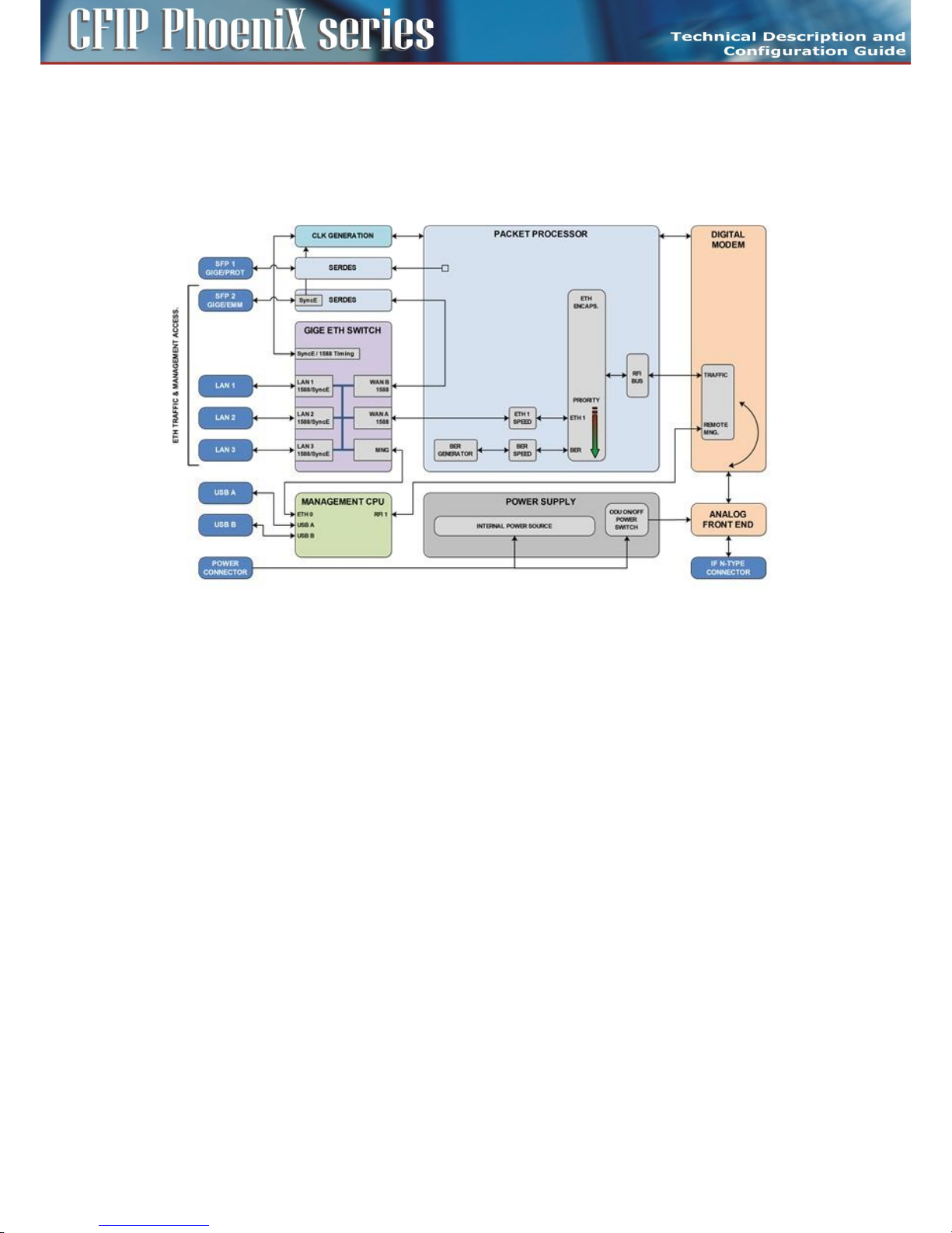
The function of the Indoor unit is evident from the block diagram in Figure 4.
Figure 4: Block diagram of the Indoor Unit
CFIP Phoenix C IDU consists of two main boards. Interface Card performs the function of data
interface, packet processor and management unit. Modem Card performs the function of digital
modem (DSP) and analogue modem (analog front end with mixers and filters).
Data are first processed by integrated Six Port Gigabit Ethernet Switch, where two WAN ports of this
switch are connected into universal Packet Processor (PBPS – Priority Based Packet System). SFP
interfaces are also directly connected into universal Packet Processor. Function of Packet Processor
depends on selected design and it is described in the section which explains such particular designs.
Digital modem then adds synchronization marks, FEC to the data stream and creates a digitally
modulated signal, which is led to the block of analog signal processing. All these parts are
interconnected inside the device over high-speed bus and are operated from the central processor
unit CPU. This block (CPU) is also accessible via management interfaces and allows the user to perform
all the settings both locally and remotely trough the IP interface in the CFIP Phoenix C IDU.
The function of Packet Processor is specific in dependence on selected design. Generally, Packet
Processor uses priority scheme which ensures that data at the internal port ETH 4 are processed with
the highest priority whereas data at the internal port ETH 1 with the lowest priority.
Page 10
10
CFIP PhoeniX C Series TDM/IP Split Mount System Technical Description and Configuration Guide • Rev. 1.0 •
© SAF Tehnika JSC 2013
Block diagram of design SINGLE
The main application in design SINGLE is a transmission of a single data stream over air. CFIP Phoenix C
IDU is configured into this mode by means of IDU management.
Packet Processor function can be simply explained in Figure 5.
Figure 5: Detailed block diagram of design SINGLE
The Ethernet Switch is configured into mode, where WAN port WAN A is connected to Packet
Processor and second WAN port WAN B is connected to port SFP 2. Port SFP 1 is without any function
in this mode. Packet Processor uses basic Ethernet stream encapsulation in combination with a BER
stream, which is transferred in time when Ethernet frames are not available.
Main Advantages
Highest data throughput, because Ethernet traffic is coded by basic encapsulation process with the
lowest data overhead.
Disadvantages
Packet Processor doesn't generate own priority packets, therefore any data stream errors are detected
only by means of Ethernet Frame's CRC inside Ethernet Switch. There is not possible to use some
options like AES along with this design due to the missing priority packet layer.
Page 11

11
CFIP PhoeniX C Series TDM/IP Split Mount System Technical Description and Configuration Guide • Rev. 1.0 •
© SAF Tehnika JSC 2013
Block diagram of design MULTI
The main application in design MULTI is a transmission of more (up to four) independent data streams
over air. CFIP Phoenix C is configured into this mode by means of IDU management.
Packet Processor function can be simply explained in Figure 6.
Figure 6: Detailed block diagram of design MULTI
The Ethernet Switch is configured into mode where both WAN ports WAN A/B are connected to
Packet Processor. Ports SFP 1 and SFP 2 are connected directly to Packet Processor as well and are
transparent for Ethernet traffic (Flow Control function must be activated on connected Ethernet
equipment). Packet Processor uses Priority based process for independent streams transport over air.
BER stream is additionally added, when throughput capacity over modem is higher than allocated
throughput over Packet Processor. Additional AES encryption can be inserted in front of modem
processing.
Main Advantages
Up to four independent data streams over air.
Disadvantages
A bit lower throughput comparing to design SINGLE when just one traffic stream is configured at IDU.
Page 12

12
CFIP PhoeniX C Series TDM/IP Split Mount System Technical Description and Configuration Guide • Rev. 1.0 •
© SAF Tehnika JSC 2013
Block diagram of design PROTECTED
The main application of design PROTECTED is a 1+1 system configuration when the protection (hitless
in specific conditions) is required.
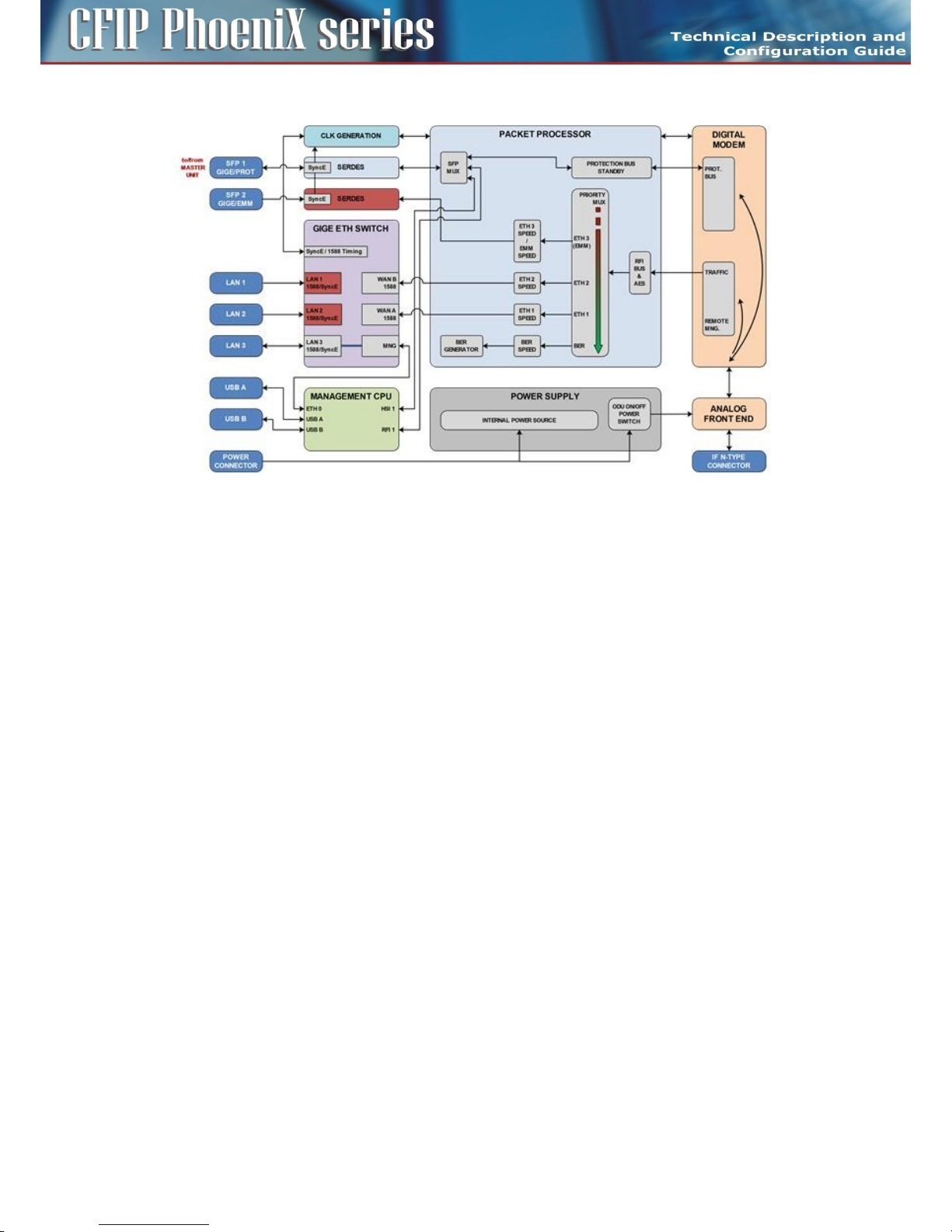
Packet Processor function for Master Unit can be simply explained in Figure 7.
Figure 7: Detailed block diagram of design PROTECTED (MASTER mode)
The Ethernet Switch is configured into mode where both WAN ports WAN A/B are connected to
Packet Processor. WAN ports WAN A/B are grouped inside Ethernet switch with appropriate LAN ports
(LAN 2/1). Port SFP 2 is also connected to Packet Processor and is transparent for Ethernet traffic
(Flow Control function must be activated on connected Ethernet equipment) or for EMM module data
stream from connected external EMM. Port SFP 1 is reserved for second IDU (Master – Slave)
interconnection.
It is strictly recommended to use port LAN 3 as out-of-band management access port.
Packet Processor uses Priority based process for independent streams transport over air. BER stream is
additionally added, when throughput capacity over modem is higher than allocated capacity for user
ports over Packet Processor. Additional AES encryption can be inserted in front of modem processing.
Protection is solved by means of Modem Card.
Packet Processor function for Slave Unit can be simply explained in Figure 8.
Page 13
13
CFIP PhoeniX C Series TDM/IP Split Mount System Technical Description and Configuration Guide • Rev. 1.0 •
© SAF Tehnika JSC 2013
Figure 8: Detailed block diagram of design PROTECTED (SLAVE mode)
The user data ports LAN 1/2, SFP 2 are deactivated (don't transmit data from IDU). Port SFP 1 is
reserved for first IDU (Master – Slave) interconnection.
It is strictly recommended to use port LAN 3 as out-of-band management access port.
Function of Packet Processor is limited to receiving direction only, but its function is not important for
system function, because complete data stream is copied from protection bus (SFP 1) directly into
digital modem. Packet Processor just adds management channels into Fiber Optic high speed stream.
Protection is solved by means of Modem Card.
Main Advantages
1+1 protection in all modes HSB, SD, FD also with interface redundancy.
Disadvantages
Two units must be used for protection mode.
Page 14
14
CFIP PhoeniX C Series TDM/IP Split Mount System Technical Description and Configuration Guide • Rev. 1.0 •
© SAF Tehnika JSC 2013
Block diagram of design AGGREGATE
The main application in design AGGREGATE is a true 2+0 system configuration (capacity doubling)
when the ETH traffic aggregation is required.
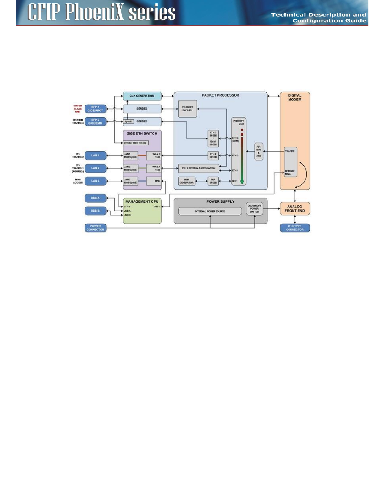
Packet Processor function for Master Unit can be simply explained in Figure 9.
Figure 9: Detailed block diagram of design AGGREGATE (MASTER mode
The Ethernet Switch is configured into mode where both WAN ports WAN A/B are connected to
Packet Processor. WAN ports WAN A/B are grouped inside Ethernet switch with appropriate LAN ports
(LAN 2/1). Port SFP 2 is also connected to Packet Processor and is transparent for Ethernet traffic
(Flow Control function must be activated on connected Ethernet equipment) or for EMM module data
stream from connected external EMM. Port SFP 1 is reserved for second IDU (Master – Slave)
interconnection. Only Ethernet traffic connected to internal channel ETH 1 can be aggregated with
traffic of Slave Unit. This mode is still combined with transmission of more traffic channels over air.
It is strictly recommended to use port LAN 3 as out-of-band management access port.
Packet Processor uses Priority based process for independent streams transport over air. BER stream is
additionally added, when throughput capacity over modem is higher than allocated capacity for user
ports over Packet Processor. Additional AES encryption can be inserted in front of modem processing.
Aggregation is solved by means of Aggregation Block inside Packet Processor.
Packet Processor function for Slave Unit can be simply explained in Figure 10.
Page 15

15
CFIP PhoeniX C Series TDM/IP Split Mount System Technical Description and Configuration Guide • Rev. 1.0 •
© SAF Tehnika JSC 2013
Figure 10: Detailed block diagram for design AGGREGATE- SLAVE
The Ethernet Switch is configured into mode where both WAN ports WAN A/B are connected to
Packet Processor. WAN ports WAN A/B are grouped inside Ethernet switch with appropriate LAN ports
(LAN 2/1). Port SFP 2 is also connected to Packet Processor and is transparent for Ethernet traffic
(Flow Control function must be activated on connected Ethernet equipment) or for EMM module data
stream from connected external EMM. Port SFP 1 is reserved for first IDU (Master – Slave)
interconnection. Traffic connected to internal port ETH 4 is an aggregate stream from Master Unit and
is transported with highest priority.
It is strictly recommended to use port LAN 3 as out-of-band management access port.
Packet Processor still uses Priority based process for independent streams transport over air. BER
stream is additionally added, when throughput capacity over modem is higher than allocated capacity
for user ports over Packet Processor. Additional AES encryption can be inserted in front of modem
processing.
Main Advantages
True 2+0 aggregation, two links with different speeds can be used for Ethernet traffic capacity
aggregation. This mode can be used as an alternative to protected mode, when one Ethernet channel
is used (no hitless).
Disadvantages
Two units must be used for aggregate mode.
Page 16

16
CFIP PhoeniX C Series TDM/IP Split Mount System Technical Description and Configuration Guide • Rev. 1.0 •
© SAF Tehnika JSC 2013
IDU block scheme in terms of IP
The following Figure 11 depicts a simplified block diagram of the CFIP Phoenix C IDU in terms of IP
management.
Figure 11: Detailed block diagram of IP management scheme
The processor itself performs the function of an IP router. The individual IP frames routing is based on
standard routing rules, in this case on static routing.
Four IP ports enter the processor (MANAGEMENT CPU)
– ETH 0 – Ethernet port of CPU with its own MAC address and all the standard features of Ethernet
interface, Primary / Secondary addresses and appropriate subnet masks are assigned to this
interface.
– RFI 1 – ppp (point-to-point) type of interface which interconnects local CPU with the remote side
CPU accessible through the separate channel inside air-frame.
– HSI 1 – ppp (point-to-point) type of interface which interconnects local CPU with the protection
unit CPU or CFIP-EXT module accessible through the separate channel inside Fiber Optic-frame.
– USB 0 – USB port which is reserved for local IP access.
Each device supports the following basic IP settings
– The primary IP address, including the mask – in the basic configuration, this address is identical
to the ports ETH 0, RFI 1 and HSI 1 (ppp unnumbered mode), the mask indicates the range of
addresses connected directly to the ETH 0 interface.
– The address of the remote radio unit (rrfi1) – together with this address there is automatically
assigned a static route of the remote device connected via port RFI 1 (microwave connection).
– The address of protection unit (rhsi1) – together with this address there is automatically
assigned a static route of the protection unit connected via port HSI 1 (Fiber Optic Connection).
– Default gateway – the address from assigned subnet for routing the frames which have different
IP address than from the range of IP addresses included in the routing table.
Page 17

17
CFIP PhoeniX C Series TDM/IP Split Mount System Technical Description and Configuration Guide • Rev. 1.0 •
© SAF Tehnika JSC 2013
Each device supports also the following advanced IP settings
– The secondary IP address, including the mask – the address is assigned to the port ETH 0, the
mask indicates the range of addresses connected directly to the ETH 0 interface. When no
conflict with address range 10.10.10.0/24 exists, there is not necessary to change this address.
– The USB IP address, including the mask – this address is assigned to the port USB 0, the mask
indicates the range of addresses connected directly to such interface. When no conflict with
address range 10.10.11.0/24 exists, there is not necessary to change this address.
– The RFI1 port IP address – it is possible to set specific IP address for internal ppp port and
change ppp mode from unnumbered to numbered one.
– The HSI1 port IP address – it is possible to set specific IP address for internal ppp port and
change ppp mode from unnumbered to numbered one.
– The File Transfer specification – this setting specifies file transfer destination. Local USB A port
can be selected (default) or FTP server by means of FTP IP specification can be used either for
firmware update from CLI or for log files storage.
– The Remote Time Server – this setting selects whether remote time server is used for time
synchronization. NTP or RDATE type can be selected for this function, appropriate IP address of
selected server must be entered.
– Static routes – the user can define additional static routes as well.
– NAT – possibility of the address translation according to the rules in the NAT table.
All above explained parameters have an influence on the type of management access either directly
on the managed unit or on the whole microwave network.
Outdoor Unit (ODU)
Outdoor microwave unit CFIP Phoenix C is available for full range of standard licensed frequency
bands and specific unlicensed bands. Microwave units for licensed frequency bands have the same
mechanical construction.
Microwave link CFIP Phoenix C of point-to-point type (in the basic configuration 1+0) consists of two
Outdoor radio Units (ODU). ODU performs the up-conversion from IF frequency from IDU (350 MHz)
to the desired transmission band, and vice versa, performs the down-conversion from received
frequency band to IF frequency (140 MHz) for the receiving part of the IDU. Power supply for ODU is
delivered through the coaxial cable (used for the connection between IDU - ODU) as well as the
software access to ODU, its management and configuration is possible only from the Indoor Unit. The
management of ODU is integrated directly in the command set of the Indoor Unit and it is an integral
part of the IDU software. For an easy primary setting of the optimal received signal level the ODU is
fitted with BNC connector where the measured DC voltage [mV] is directly proportional to the level of
Received Signal Strength (RSSI).
Page 18

18
CFIP PhoeniX C Series TDM/IP Split Mount System Technical Description and Configuration Guide • Rev. 1.0 •
© SAF Tehnika JSC 2013
Figure 12: Block diagram of the Outdoor Unit
Outdoor unit is an integral part of the antenna system. ODU is mounted behind the parabolic antenna.
In dependence on requested application distances there are available antennas with diameters of 30,
60, 90, 99, 120, 180, 240 and 300 cm.
ODU for license frequency bands
Outdoor units in the version for the license frequency bands meet the international standards and
requirements for this type of equipment (especially ETSI EN 302 217). The modulation scheme is
adjustable from QPSK to 256 QAM, the output power is in the range between 0 to 30 dBm depending
on the selected frequency band and the type of modulation scheme. A maximum transmission date
rate is 365 Mbps in 1+0 mode.
For technical reasons, each frequency band is covered by more (three or four) pairs of microwave
units, where one pair is tunable in the low portion of the band (in low sub-band), the second/third
pair in the middle portion of the band (in middle sub-band) and the last pair in the high portion of the
band (in high sub-band). Each pair then consists of two radio units (ODU), where one unit transmits in
the upper part and the second unit in the bottom part of the given sub-band, the frequency
separation is then known as the duplex spacing (Tx/Rx).
In consequence of the statement above the ODU, that is tunable in lower part of the particular subband of given frequency, can work only with ODU tunable in higher part of the same sub-band of the
same frequency.
There are only two connectors accessible on the ODU, N connector for connecting with the IDU via
coaxial cable and BNC connector for measurement of Received Signal Strength (RSSI). Next to the BNC
connector is located grounding screw.
Page 19

19
CFIP PhoeniX C Series TDM/IP Split Mount System Technical Description and Configuration Guide • Rev. 1.0 •
© SAF Tehnika JSC 2013
Figure 13: Preview of Outdoor Unit for licensed bands
Attaching the ODU to the antenna is done with an integrated waveguide transition (Microwave
adapter) and it is mechanically realized with four flexible clips.
Page 20

20
CFIP PhoeniX C Series TDM/IP Split Mount System Technical Description and Configuration Guide • Rev. 1.0 •
© SAF Tehnika JSC 2013
ODU technical specifications
CFIP ODU RSL at 10-6 (dBm) and Total Payload Capacity (Mbps)
BW***, MHz
Modulation
FEC****
6
GHz 7 GHz 8 GHz
10 GHz
11 GHz
13 GHz
15 GHz
18 GHz
23 GHz
26 GHz
38* GHz
Bit rate, Mbps
3.5
QPSK
Strong
-97
-95
-95
-97
-96
-95
-93,5
-95
-97
-96,5
-93,5
3
16APSK
Strong
-90,5
-88
-88
-90
-89
-88
-88
-88,5
-90
-89,5
-86,5 7 32APSK
Strong
-87
-85
-85,5
-87
-86
-85
-85
-85,5
-87
-86,5
-83,5
9
64QAM
Strong
-84
-81,5
-82
-84
-83
-82
-82
-82
-83,5
-83
-80
13
Weak
-81,5
-79
-79,5
-81
-80
-79,5
-79
-79,5
-81
-81
-78
14 7 QPSK
Strong
-93
-92
-92
-94
-93
-92,5
-91
-92
-94
-93,5
-90,5 8 16APSK
Strong
-86,5
-85
-85,5
-87,5
-86,5
-85,5
-85
-85,5
-87,5
-87
-84
17
32APSK
Strong
-83,5
-82,5
-83
-84,5
-83,5
-83
-82,5
-83
-84,5
-84
-81
21
64QAM
Strong
-80
-79
-80
-81,5
-80,5
-79,5
-79,5
-79,5
-81,5
-80,5
-77,5
28
128QAM
Strong
-77
-76
-76,5
-78
-77
-76
-76,5
-76
-78
-77,5
-74,5
34
Weak
-75
-73,5
-75
-76
-75
-74,5
-74
-74
-75,5
-75,5
-72,5
36
14
QPSK
Strong
-90
-90,5
-90
-91
-90
-90
-89
-90,5
-91
-90,5
-87,5
17
16APSK
Strong
-83,5
-83,5
-83,5
-84,5
-83,5
-83,5
-83
-84
-84
-83,5
-80,5
34
32APSK
Strong
-80
-80
-80,5
-81,5
-80,5
-80
-80
-80,5
-80,5
-80,5
-77,5
45
64QAM
Strong
-77,5
-77,5
-78
-79
-78
-77,5
-77,5
-78
-78,5
-78
-75
57
128QAM
Strong
-74,5
-74,5
-75
-75,5
-74,5
-74,5
-74
-75
-75
-75
-72
68
256QAM
Strong
-71
-71
-71,5
-72
-71
-70,5
-70,5
-72
-71,5
-71,5
-68,5
79
Weak
-67,5
-67,5
-68
-69
-68
-67,5
-67
-68
-65,5
-68
-65
86
28
QPSK
Strong
-90.5
-89.5
-89
-88.5
-89.5
-89.5
-89
-90
-89
-91.5
-85
35
16APSK
Strong
-84.5
-83
-83
-82.5
-83.5
-83.5
-83
-84
-83
-85
-79
69
32APSK
Strong
-81.5
-80
-80
-80
-80.5
-80.5
-80.5
-80.5
-80
-82
-76
88
64QAM
Strong
-79
-77.5
-77.5
-77
-78
-77.5
-77
-78
-77.5
-79.5
-73.5
115
128QAM
Strong
-75.5
-74.5
-74
-73.5
-74.5
-74.5
-74
-75.5
-74
-76.5
-70
138
256QAM
Strong
-72.5
-71
-70.5
-70.5
-71
-71
-70.5
-72
-71
-73
-67
161
Weak
-69
-67
-66
-66
-67
-67
-66.5
-69
-67.5
-70
-63.5
174
Page 21

21
CFIP PhoeniX C Series TDM/IP Split Mount System Technical Description and Configuration Guide • Rev. 1.0 •
© SAF Tehnika JSC 2013
CFIP ODU RSL at 10-6 (dBm) and Total Payload Capacity (Mbps)
BW***, MHz
Modulation
FEC****
6
GHz 7 GHz 8 GHz
10 GHz
11 GHz
13 GHz
15 GHz
18 GHz
23 GHz
26 GHz
38* GHz
Bit rate,
Mbps
40
QPSK
Strong
-89
-87.5
-88
-87.5
-88
-88
-88
-88
-87.5
-89.5
-83.5
49
16APSK
Strong
-82.5
-81.5
-81.5
-81
-82
-82
-81.5
-82.5
-81
-83.5
-77
98
32APSK
Strong
-80
-78.5
-79
-78.5
-79.5
-79.5
-79
-79.5
-78.5
-80.5
-74.5
127
64QAM
Strong
-77
-76
-75.5
-75.5
-76.5
-76
-76
-77
-75.5
-78
-71.5
163
128QAM
Strong
-74
-73
-72.5
-72.5
-73.5
-73
-72.5
-73.5
-72.5
-74.5
-68.5
196
256QAM
Strong
-70.5
-69.5
-69
-68.5
-69.5
-69.5
-69
-70.5
-69
-71
-65
229
Weak
-68
-67
-64.5
-64.5
-65.5
-65
-65
-67.5
-66.5
-68.5
-62.5
245
56
QPSK
Strong
-87
-85.5
-86
-85.5
-87
-86.5
-86
-87
-85.5
-88
-81.5
72/67**
16APSK
Strong
-81
-80
-79.5
-79.5
-80.5
-80
-79.5
-80.5
-79.5
-82
-75.5
145/135**
32APSK
Strong
-78
-77
-77.5
-77
-78
-77.5
-77
-77.5
-76.5
-79
-72.5
182
64QAM
Strong
-75.5
-74.5
-74
-73.5
-74.5
-74.5
-74
-75.5
-74
-76
-70
240
128QAM
Strong
-72
-71
-71
-70.5
-71.5
-71.5
-71
-72
-70.5
-73
-66.5
287
256QAM
Strong
-68.5
-67.5
-67
-66.5
-68
-67.5
-67
-68.5
-67
-69.5
-63
335
Weak
-64
-63
-63
-62.5
-63.5
-63
-62.5
-64.5
-62.5
-65
-58.5
363
CFIP ODU Tx Power
Modulation
Standard/High Tx Power, dBm
6, 7, 8 GHz
10, 11, 13, 15 GHz
18, 23, 26*
GHz
38* GHz
4QAM
+19/+27
+19/+25
19
17
16QAM
+18/+26
+18/+24
18
16
32QAM
+17/+25
+17/+23
17
15
64QAM
+15/+23
+15/+21
15
13
128QAM
+15/+23
+15/+21
15
13
256QAM
+12/+20
+12/+18
12
10
Page 22

22
CFIP PhoeniX C Series TDM/IP Split Mount System Technical Description and Configuration Guide • Rev. 1.0 •
© SAF Tehnika JSC 2013
CFIP ODU waveguide flange sizes
6 GHz
7, 8 GHz
10, 11 GHz
13, 15 GHz
18, 23 GHz
26 GHz
38 GHz
N-type
UBR84
UBR100
UBR140
UBR220
UBR260
UBR320
Max. Power
consumption
SP: 13-27 W; HP: 21-39 W
Page 23

23
CFIP PhoeniX C Series TDM/IP Split Mount System Technical Description and Configuration Guide • Rev. 1.0 •
© SAF Tehnika JSC 2013
External Multiplexer Modules
The basic function of External Multiplexer Modules is multiplexing of specific data types (E1, T1, ASI)
into one high speed data stream which is then transported over Fiber Optic interface (SFP2) to
connected IDU. Such coded data stream is muxed with other data sources (ETH channels) inside IDU
and transmitted to the remote IDU and appropriate remote External Multiplexer Module. Up to four
External Multiplexer Modules can be connected in series to one IDU.
Management of all External Multiplexer Modules is integrated inside IDU management system,
therefore the configuration of all External Multiplexer Module parameters is similar to IDU
configuration.
The External Multiplexer Module unit must be connected to the power supply with a nominal voltage
of -48 VDC and GND must be connected to the positive pole.
Extension module CFIP-16E1/T1-EXT
Device CFIP-16E1/T1-EXT (External Multiplexer Module) provides E1/T1 extension for Indoor Units of
CFIP Phoenix C product line. The CFIP-16E1/T1 module enables multiplexing up to 16 E1 / T1 circuits.
The multiplexer features a basic unit with 16 x E1/T1 built-in ports and 2 x SFP 1000Base-SX ports. The
compact, simple to configure, and easily scalable design can provide up to 64 x E1/T1 solution or
enables cascading with other extension devices CFIP (e.g. CFIP-ASI, CFIP-E3). The configuration is
performed from GUI of Indoor Unit (set-up of basic mode E1/T1, add/drop multiplexer, backup). The
real overall capacity for TDM is allocated in the PBPS based on true selected ports E1/T1 in GUI of
Indoor Unit.
Priority Base Packet System (PBPS) is proprietary multiplexer system.
Connectors on the Extension module CFIP-16E1/T1-EXT front panel
– E1/T1 PORTS – RJ-45 connectors for G.703 signals connection (by default unbalanced)
– SFP 1 UPLINK1 – master SFP port reserved for connection to IDU or to master Extension module
card in Extension module chain
– SFP 2 UPLINK2 – slave SFP port reserved for connection to slave Extension module card in
Extension module chain or to relay IDU in add/drop configuration
– -48 VDC – power supply connector, + pole is grounded inside the device
– Grounding connector
The position and indexing of 16 E1 user ports indicates the legend below:
Page 24

24
CFIP PhoeniX C Series TDM/IP Split Mount System Technical Description and Configuration Guide • Rev. 1.0 •
© SAF Tehnika JSC 2013
All the ports are protectcted against ESD (electrostatic discharge), CDE (Cable Discharge Events), and
lightning.
In case of connecting 16E1 balanced RJ-45 interface to customer’s unbalanced BNC E1 interface ports
the following cable must be used:
Pinout for this cable is as follows:
LED indicators on the CFIP-16E1/T1-EXT – system status
– STATUS – indication of the LOCAL Extension module status
- Lights – status OK (card enabled, proper communication with IDU)
- Flashes – status WARNING (card is not enabled in the system or no communication with IDU)
- No light – status ERROR (a firmware is not loaded into Extension module HW)
– POWER – indication that EMM is under power (green LED)
- Lights – power ON
- No light – power OFF
Pin1 – Rx-
Pin2 – Rx+
Pin4 – Tx-
Pin5 – Tx+
Page 25

25
CFIP PhoeniX C Series TDM/IP Split Mount System Technical Description and Configuration Guide • Rev. 1.0 •
© SAF Tehnika JSC 2013
LED indicators on the CFIP-16E1/T1-EXT – port status
– SFP 1/2 LINK – indication of presented signal at SFP port
- Flashes – signal detected and synchronized, valid communication with IDU
- No light – no correct signal detected
– LINK – indication of G.703 link status on appropriate port (green LED)
- Lights – signal detected at port
- No light – no link at port
– AIS – indication of AIS signal at appropriate G.703 port
- Lights – AIS signal detected
- No light – no AIS at appropriate G.703 port
General application with CFIP-16E1/T1-EXT
External multiplexer 16 x E1 or 16 x T1. This application is using Priority Base Packet System (PBPS is
proprietary multiplexer system) for 1 up to 16 E1 / T1 circuits multiplexing. The data stream PBPS is
first completed with data channel for communication with the IDU and subsequently is packed into
standard Ethernet frame for transmission over the network.
Page 26

26
CFIP PhoeniX C Series TDM/IP Split Mount System Technical Description and Configuration Guide • Rev. 1.0 •
© SAF Tehnika JSC 2013
Up to 64 E1/T1 external multiplexer application
Up to 4 x CFIP-16E1/T1-EXT modules can be connected into cascade and thus get the maximum
quantity of 64 E1 / T1 channels (ports). Port Nr. 2 SFP 1000Base-SX is dedicated for the modules
interconnection into cascade. The configuration of all CFIP external modules is performed from GUI of
Indoor Unit (set-up of basic mode E1/T1, add/drop multiplexer, backup).
Page 27

27
CFIP PhoeniX C Series TDM/IP Split Mount System Technical Description and Configuration Guide • Rev. 1.0 •
© SAF Tehnika JSC 2013
1+1 application with CFIP-16E1/T1-EXT
The combination of 1+1 protected scheme with extension module CFIP-16E1/T1-EXT.
Add-drop multiplexer application
Page 28

28
CFIP PhoeniX C Series TDM/IP Split Mount System Technical Description and Configuration Guide • Rev. 1.0 •
© SAF Tehnika JSC 2013
Management and configuration examples of CFIP-16E1/T1-EXT
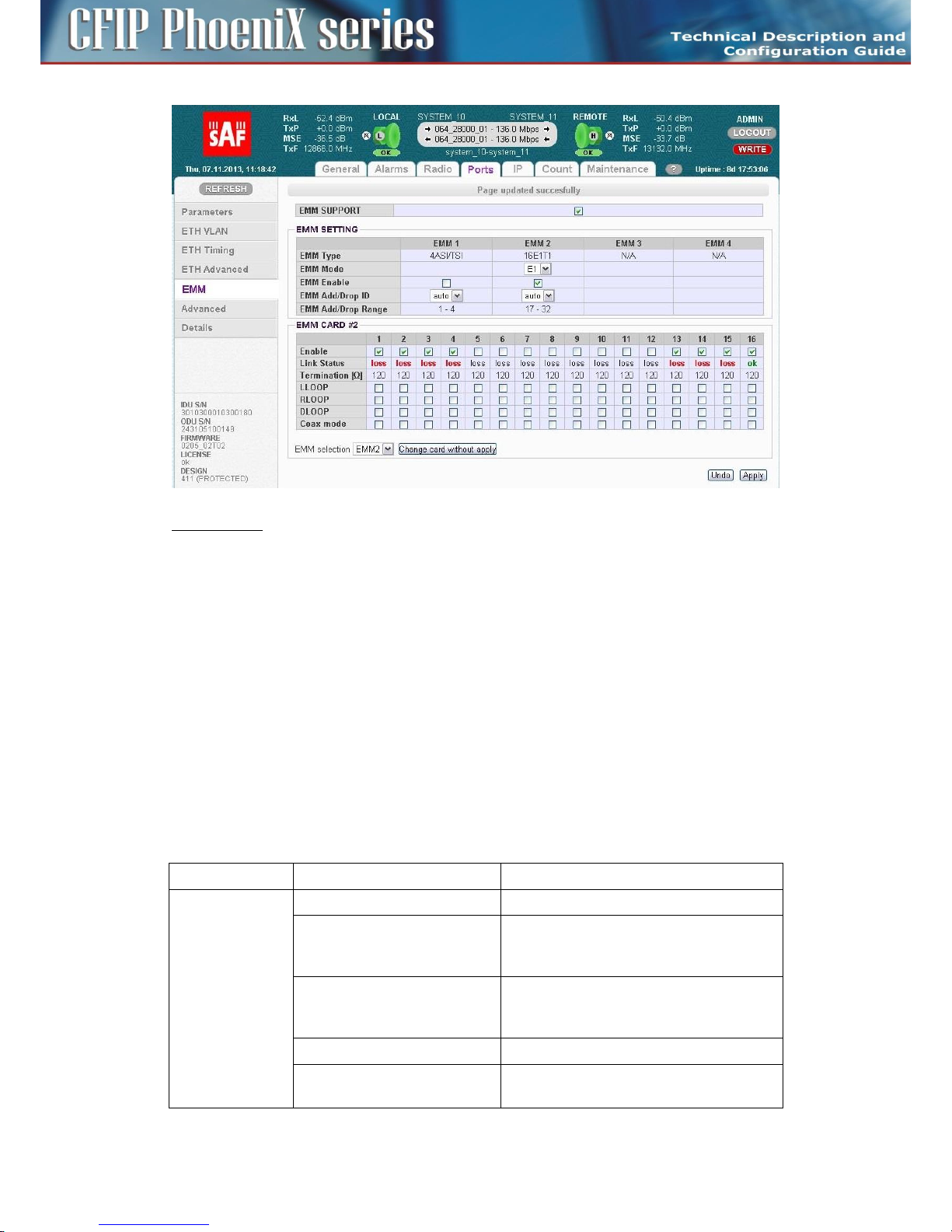
The configuration and status of the module can be found in web GUI in Ports/EMM management
menu:
EMM SUPPORT
This check box changes mode of SFP2 port from standard Gigabit ETH to proprietary EMM (Expansion)
mode. When EMM mode is enabled by this checkbox, IDU starts communication with all connected
EMM expansion modules.
EMM SETTING
– EMM Type - displays the type of connected EMM (Expansion) card.
- N/A - indicates that particular position is empty;
- RELAY-IDU - indicates that the relay IDU is connected directly to IDU SFP port (relay
application) or to EMM slave SFP port (add/drop configuration).
– EMM Mode – this function is related only to CFIP-16E1/T1-EXT module and allows to choose
traffic interface mode between E1 and T1
– EMM Enable – enables or disables generation/reception of data frames to/from Fiber Optic
stream. When enabled then particular EMM module occupies appropriate range of traffic port
channels
– EMM Add/Drop ID – specifies EMM Add/Drop Range – channel range which is in use by current
EMM module. In “auto” mode EMM module occupies port channel range according to its
position in EMM modules chain. In case of specific range of Add/Drop port channels, manual
Add/Drop ID setting is available as well.
– EMM Add/Drop Range – displays appropriate port channel range according to the EMM module
position and EMM Add/Drop ID setting.
Configuration menu of particular EMM (Expansion) module can be selected in dropdown box “EMM
selection”on the bottom of the EMM configuration page:
After selecting particular EMM module and pressing on “Change card without apply”, appropriate
EMM module’s configuration menu will be displayed:
Page 29
29
CFIP PhoeniX C Series TDM/IP Split Mount System Technical Description and Configuration Guide • Rev. 1.0 •
© SAF Tehnika JSC 2013
EMM CARD #x settings for CFIP-16E1/T1-EXP
- Port/Channel Number - a number of E1/T1 ports (channels), the number in red indicates alarm
status of appropriate internal channel (check alarm page for more details regarding this status)
- Enable – selects which E1/T1 ports are enabled for customer traffic connection.
Selecting/enabling of ports reserves appropriate capacity allocation from IDU for this type of
traffic even customer traffic is not carried (e.g. cable is disconnected) over any of enabled
channels.
- Line Status – displays the actual status of E1/T1 port or appropriate internal traffic channel
- Termination – displays the actual impedance matching of E1/T1 port
- LLOOP – local loopback configuration, incoming data stream from E1/T1 port is looped
- RLOOP – remote loopback configuration, receiving data stream from Fibre Optics is looped.
- DLOOP – dual loopback configuration, both data stream directions are looped inside the IDU
- Coax Mode – allows choosing E1/T1 interface mode (impedance) between standard 120 Ohm
balanced to 75 Ohm unbalanced. When enabled – 75 Ohms are selected. Chosen interface mode
is displayed in “Termination” row.
Technical specification of CFIP-E1/T1-EXT module
Traffic Interfaces
Item
Parameter
Value
CFIP-16E1/T1-EXT
Number of Ports
16 (16xRJ-45)
Interface
G.703-E1 balanced 120ohm for E1 mode
G.703-E1 unbalanced 75 ohm for E1 mode
T1.102-T1/100 ohm for T1 mode
Specification Compliance
T1.102, AT&T Pub 62411, T1.231, T1.403, ITUT G.703, G.742, G.775, G.823, ETS 300 166,
and ETS 300 233
Coding
HDB3 for E1 mode, B8ZS for T1 mode
Speed
2.048 Mbps for E1 mode, 1.554Mbps for T1
mode
Page 30

30
CFIP PhoeniX C Series TDM/IP Split Mount System Technical Description and Configuration Guide • Rev. 1.0 •
© SAF Tehnika JSC 2013
Item
Parameter
Value
IDU direction interface
1x SFP 1000Base-SX (proprietary GIGE
protocol)
for connection with CFIP Phoenix C IDU
EXT module extension interface
1x SFP 1000Base-SX (proprietary GIGE
protocol)
for connection with additional EMM module
EXT module scalability
Up to 64 E1 / T1 with combination of 4x
EMM-16E1/T1 modules in series
Network Management System
Item
Parameter
Value
Ports
Main NMS ports
2x SFP 1000Base-SX (proprietary GIGE
protocol) from IDU
NMS form
Protocols
Proprietary
Management Speed
1Mbps
GUI
Type
WEB based as additional function of IDU,
folder PORTS
SNMP
Version
SNMP v1, SNMP v2c, SNMP v3 IDU support
Read access
Complete MIB IDU support
Write access
Sub-set of link parameter IDU support
Security
Licenses
Time limited/permanent IDU Support
Access levels
guest/user/admin with password security IDU
Support
Miscellaneous
Item
Parameter
Value
Mechanical
Dimension [w x h x d]
224mm x 44mm x 134mm
Weight
1,3 kg
Protection
EN 60529 (IP31)
Input Voltage Level
EMM only
-20 VDC up to -60 VDC (standard version)
Power
Consumption
CFIP-16 x E1/T1-EXT
< 9 W
Environmental
Operational
Conditions
Temperature
-5 ° to +45 °C
Humidity
0 to 95%, Non condensing
Altitude
4,500 Meters
Compliance
Operation
ETSI EN 300 019, Part 1-3, Class 3.2
Storage
ETSI EN 300 019, Part 1-1, Class 1.2
Transportation
ETSI EN 300 019, Part 1-2, Class 2.3
Power
EN 300 132-2
EMC
EN 55022 class B,
EN 61000-4-2,3,4,5,6,8,11
Page 31
31
CFIP PhoeniX C Series TDM/IP Split Mount System Technical Description and Configuration Guide • Rev. 1.0 •
© SAF Tehnika JSC 2013
Item
Parameter
Value
EN 61000-3-2,3
Safety
IEC 60950-1/EN 60950-1
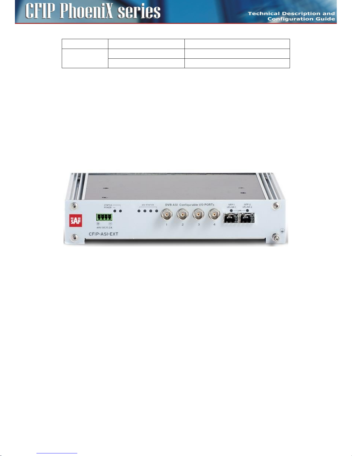
Extension module CFIP-ASI-EXT
Extension card CFIP-ASI-EXT (External Multiplexer Module) provides ASI extension for CFIP Phoenix C
Indoor Units. The CFIP-ASI-EXT card enables multiplexing up to four ASI channels into compact stream
which is directed over fiber optic connection to/from CFIP Phoenix C IDU. The multiplexer features a
basic unit with 4 x ASI built-in ports (one BNC per ASI channel) and 2 x SFP 1000Base-SX ports.
The compact, simple to configure, and easily scalable design enables cascading with other CFIP
Phoenix C extension devices (e.g. CFIP-16E1/T1-EXT). The configuration is performed from GUI of
Indoor Unit.
The real overall capacity for ASI is allocated in the PBPS based on true selected ASI ports in GUI of
Indoor Unit.
Priority Base Packet System (PBPS) is proprietary multiplexer system.
CFIP-ASI-EXT Users ports
Each ASI channel can be independently configured into Tx or Rx mode. Following port combinations
are available by this setting
- 4x ASI Tx (unidirectional)
- 3x ASI Tx, 1x ASI Rx (bidirectional)
- 2x ASI Tx, 2x ASI Rx (bidirectional)
- 1x ASI Tx, 3x ASI Rx (bidirectional)
- 4x ASI Rx (unidirectional)
Connectors on the CFIP-ASI-EXT front panel
– DVB ASI – four configurable I/O DVB-ASI ports (75 Ohm)
– SFP 1 UPLINK1 – master SFP port reserved for connection to IDU or to master Extension module
card in Extension module chain
– SFP 2 UPLINK2 – slave SFP port reserved for connection to slave EMM card in Extension module
chain or to relay IDU in add/drop configuration
– -48 VDC – power supply connector, + pole is grounded inside the device
– Grounding connector
Page 32

32
CFIP PhoeniX C Series TDM/IP Split Mount System Technical Description and Configuration Guide • Rev. 1.0 •
© SAF Tehnika JSC 2013
LED indicators on the CFIP-ASI-EXT – system status
– STATUS – indication of the LOCAL EMM status
- Lights – status OK (card enabled, proper communication with IDU)
- Flashes – status WARNING (card is not enabled in the system or no communication with
IDU or configuration was not finished yet)
- No light – status ERROR (a firmware is not loaded into Extension module HW)
– POWER – indication that Extension module is under power (green LED)
- Lights – power ON
- No light – power OFF
LED indicators on the CFIP-ASI-EXT – ports status
– SFP 1/2 LINK – indication of presented signal at SFP port
- Flashes – signal detected and synchronized, valid communication with IDU
- No light – no correct signal detected
– ASI STATUS – indication of ASI status; depends on mode settings of appropriate ASI port (1-4):
– Port in Tx Mode
– Blink – ASI signal presented, sending data
– No light – no data (IDLE status)
– Port in Rx Mode
– Lights – signal detected but in IDLE or nosync mode
– Blink – incoming ASI signal
– No light – no ingress signal detected
General application with CFIP-ASI-EXT
Page 33

33
CFIP PhoeniX C Series TDM/IP Split Mount System Technical Description and Configuration Guide • Rev. 1.0 •
© SAF Tehnika JSC 2013
This application uses combination of CFIP Phoenix C IDU with selected MULTI design and one CFIPASI-EXT card in unidirectional mode (Tx ports at one link side, Rx ports at opposite link side).
The Priority Base Packet System (PBPS - proprietary multiplexer system) is used for 1 up to 4 ASI
channels multiplexing. The data PBPS stream is first completed with management data channel for
communication with the connected IDU and subsequently is packed into standard Ethernet frame for
transmission over FO interconnection. The PBPS packets from CFIP-ASI-EXT are then combined with
another PBPS packets from internal data sources (Ethernet) assembled on IDU according to default
priority scheme.
CFIP-ASI-EXT cascading
Up to 4 x CFIP-EXT modules can be connected into cascade and thus get the maximum quantity of
external ports (any combination of CFIP-ASI-EXT, CFIP-16E1T1-EXT). Port Nr. 2 SFP 1000Base-SX is
dedicated for the modules interconnection into cascade. The configuration of all CFIP-EXT modules is
performed from GUI of Indoor Unit.
Be sure that radio capacity is adequate to required port capacity on CFIP-EXTs.
1+1 application with CFIP-ASI-EXT
This application uses combination of two CFIP Phoenix C IDUs with selected PROTECTED design and
one CFIP-ASI-EXT card in unidirectional mode (Tx ports at one link side, Rx ports at opposite link side).
The PBPS is used for 1 up to 4 ASI channels multiplexing. The data PBPS stream is first completed with
management data channel for communication with the connected master IDU and subsequently is
packed into standard Ethernet frame for transmission over FO interconnection. The PBPS packets
from CFIP-EXT are then combined with another PBPS packets from internal data sources (Ethernet)
assembled on IDU according to default priority scheme. The port SFP2 on CFIP-ASI-EXT can be
optionally connected into slave IDU for possibility to change slave/master mode of IDUs.
Page 34

34
CFIP PhoeniX C Series TDM/IP Split Mount System Technical Description and Configuration Guide • Rev. 1.0 •
© SAF Tehnika JSC 2013
Management and configuration examples of CFIP-ASI-EXT
The configuration and status of the module can be found in web GUI in Ports/EMM management
menu:
EMM SUPPORT
This check box changes mode of SFP2 port from standard Gigabit ETH to proprietary EMM (Expansion)
mode. When EMM mode is enabled by this checkbox, IDU starts communication with all connected
EMM expansion modules.
EMM SETTING
– EMM Type - displays the type of connected EMM (Expansion) card.
- N/A - indicates that particular position is empty;
- RELAY-IDU - indicates that the relay IDU is connected directly to IDU SFP port (relay
application) or to EMM slave SFP port (add/drop configuration).
– EMM Mode – this function is related only to CFIP-16E1/T1-EXT module and allows to choose
traffic interface mode between E1 and T1
– EMM Enable – enables or disables generation/reception of data frames to/from Fiber Optic
stream. When enabled then particular EMM module occupies appropriate range of traffic port
channels
– EMM Add/Drop ID – specifies EMM Add/Drop Range – channel range which is in use by current
EMM module. In “auto” mode EMM module occupies port channel range according to its
position in EMM modules chain. In case of specific range of Add/Drop port channels, manual
Add/Drop ID setting is available as well.
– EMM Add/Drop Range – displays appropriate port channel range according to the EMM module
position and EMM Add/Drop ID setting.
Configuration menu of particular EMM (Expansion) module can be selected in dropdown box “EMM
selection”on the bottom of the EMM configuration page:
After selecting particular EMM module and pressing on “Change card without apply”, appropriate
EMM module’s configuration menu will be displayed:
Page 35

35
CFIP PhoeniX C Series TDM/IP Split Mount System Technical Description and Configuration Guide • Rev. 1.0 •
© SAF Tehnika JSC 2013
EMM CARD #x settings for CFIP-ASI-EXP
- Port/Channel Number - a number of ASI ports (channels)
- Enable – selects which ASI ports are enabled for DVB ASI connection. The necessary link capacity
is automatically allocated according to sum of all ASI Rx streams.
- Link Status – displays the actual status of ASI port:
- Status indications in case if Rx mode is set:
- ok - a valid ASI signal is present at appropriate input port
- ok - a valid ASI signal is present at appropriate input port, but the port is not enabled for
traffic application
- Idle - ASI signal detected and successfully synchronized, but the signal does not contain
user data (MPEG stream is missing)
- Idle - ASI signal detected and successfully synchronized but the signal does not contain
user data (MPEG stream is missing) and the particular port is not enabled for traffic
application
- nosync - indicates that synchronization was not established for current received ASI signal
- nosync - indicates that synchronization was not established for current received ASI signal
and the port is not enabled for traffic application
- loss - no signal detected at ASI input port
- loss - no signal detected at ASI input port and the port is not enabled for traffic
application
- Status indications in case if Tx mode is set:
- ok - a valid inbound signal is present and transmitted via appropriate ASI port
- ok - a valid inbound signal is present, but the port is not enabled for transmitting
- Idle - ASI signal detected and successfully synchronized but the signal does not contain
user data (MPEG stream is missing)
- Idle - ASI signal detected and successfully synchronized but the signal does not contain
user data (MPEG stream is missing), and the particular port is not enabled for traffic
application
- Mode – specifies if the particular port operates in Rx (ingress from coaxial cable) or Tx (egress to
coaxial cable) mode
- Data Source – specifies source for Tx signal. Either remote ASI port (Remote CH1-4) or one of
available local ASI Rx port (Local Ch1-4) can be chosen. This setting is available in Tx mode only
Page 36

36
CFIP PhoeniX C Series TDM/IP Split Mount System Technical Description and Configuration Guide • Rev. 1.0 •
© SAF Tehnika JSC 2013
- Speed Limit(Rx) [Mbps] - maximal data rate for inbound traffic to avoid overload of overall link
capacity. This settings is available in Rx mode only
CFIP-ASI-EXT technical specifications
Traffic Interfaces
Item
Parameter
Value
CFIP-ASI-EXT
Number of traffic Ports
4 (4xBNC)
Interface
unbalanced 75 ohm
Tx Output Voltage (p-p)
800 mV
Min Rx. Sensitivity
200 mV (for D21.5 idle pattern)
Specification Compliance
DVB-ASI, EN/ISO/IEC 13818-1, ETS 300 429
Coding
8B/10B, MPEG-2 TS
Port Speed
270Mbit/s at BNC port
Max. speed for ASI channel
216 Mbps
ASI channel shaping
8-216 Mbps
Packet format
188 bytes / 204 bytes (with FEC)
IDU inteconnection interface
1x SFP 1000Base-SX (proprietary GIGE protocol)
for connection with CFIP Phoenix C IDU
CFIP-EXT extension interface
1x SFP 1000Base-SX (proprietary GIGE protocol)
for connection with additional CFIP-EXT module
CFIP-EXT scalability
Up to four CFIP-EXT cards in cascade
Network management system
Item
Parameter
Value
Ports
Main NMS ports
2x SFP 1000Base-SX (proprietary GIGE protocol)
from IDU
NMS form
Protocols
Proprietary
Management Speed
1Mbps
GUI
Type
WEB based as additional function of IDU, folder
PORTS
SNMP
Version
SNMP v1, SNMP v2c, SNMP v3 IDU support
Read access
Complete MIB IDU support
Write access
Sub-set of link parameter IDU support
Security
Licenses
Time limited/permanent IDU Support
Access levels
guest/user/admin with password security IDU
Support
Miscellaneous
Item
Parameter
Value
Mechanical
Dimension [w x h x d]
224mm x 44mm x 134mm
Weight
1,3 kg
Page 37

37
CFIP PhoeniX C Series TDM/IP Split Mount System Technical Description and Configuration Guide • Rev. 1.0 •
© SAF Tehnika JSC 2013
Item
Parameter
Value
Protection
EN 60529 (IP31)
Input Voltage Level
CFIP-EXT only
-20 VDC up to -60 VDC (standard version)
Power
Consumption
CFIP-ASI-EXT
< 9 W
Environmental
Operational
Conditions
Temperature
-5 ° to +45 °C
Humidity
0 to 95%, Non condensing
Altitude
4,500 Meters
Compliance
Operation
ETSI EN 300 019, Part 1-3, Class 3.2
Storage
ETSI EN 300 019, Part 1-1, Class 1.2
Transportation
ETSI EN 300 019, Part 1-2, Class 2.3
Power
EN 300 132-2
EMC
EN 55022 class B,
EN 61000-4-2,3,4,5,6,8,11
EN 61000-3-2,3
Safety
IEC 60950-1/EN 60950-1
Extension module CFIP-ASI-EXT with Time Synchronization Interface (TSI)
The CFIP-ASI&TSI-EXT is extension module for CFIP Phoenix C IDU with built-in Timing module
featuring temperature stabilized oscillator (OCXO).
Its function is one-direction distribution of precise time synchronization pulses (1PPS = 1 pulse per
second) and 10MHz precise frequency signal from Master side to Slave side over the link. The CFIPASI&TSI-EXT requires external source of precise time synchronization pulses. External source has to
support pulse stability 10e-8 or better.
The source of precise time is taken from TSI1/1PPS input port. If the Timing module recognizes stable
reference input signal then the Timing module synchronizes to this input signal. If the source signal is
not presented or it is not stable enough, the Timing module will switch to "holdover" mode. In this
mode the Timing module is able to operate as standalone and hold and generate both 1PPS and
10MHz signal with precision of 10e-8. This signal is transmitted to the Master IDU. The IDU’s internal
clock is synchronized with this signal. Then this signal is re-distributed to remote side. Any signal
delays and fluctuations are automatically compensated by built-in precision time algorithm. Complete
and precise synchronization should be available in 10 minutes after turning on the devices. The
synchronization is periodically corrected over time - longer run means more precise synchronization.
The long time stable and synchronized frequency is stored into non-volatile memory once per day and
such stored value is used during holdover state for generating stable frequency and time output
signals.
The source of precise time synchronization can be altered by means of GPS. It requires active external
antenna with gain app. 25dB.
Page 38

38
CFIP PhoeniX C Series TDM/IP Split Mount System Technical Description and Configuration Guide • Rev. 1.0 •
© SAF Tehnika JSC 2013
The module contains additional 5 connectors in comparison to basic ASI module:
Master module ports
– TSI1 in:
– 1PPS - input source of 1PPS pulse (required)
– 10MHz - source of 10MHz signal (not required), if not presented the 10MHz signal will be
generated by the Timing module
– TSI2 out:
– 1PPS - redistribution of the 1PPS signal from the source or Time module in "holdover" mode
– 10MHz - redistribution of the 10MHz signal from the source or Time module
– GPS ant – The connector for external GPS antenna. This is optional and only for cases when there
is needed GPS signal as source of precise time.
Slave module ports
– TSI1 out:
– 1PPS - redistribution of the 1PPS signal from the source (Master TSI via RFI)
– 10MHz - redistribution of the 10MHz signal from the source or Time module (Master TSI via
RFI)
– TSI2 out:
– 1PPS - redistribution of the 1PPS signal from the source (Master TSI via RFI)
– 10MHz - redistribution of the 10MHz signal from the source or Time module (Master TSI via
RFI)
– GPS ant – The connector for external GPS antenna. This is optional and only for cases when there
is needed GPS signal as source of precise time.
Page 39

39
CFIP PhoeniX C Series TDM/IP Split Mount System Technical Description and Configuration Guide • Rev. 1.0 •
© SAF Tehnika JSC 2013
Basic block diagram of the CFIP-ASI&TSI_EXT
The blue lines represent the separate time transfer (1PPS/10MHz) path, the green
lines represent path of ASI signals and red lines represent the common path of
timing, ASI and other traffic signals.
LED indicators on the CFIP-ASI&TSI-EXT – Master
- MASTER (IN) LED – indicates that the device operates in master mode
- SYNC LED – LED is ON when the IDU-Extension Module Time Sync is in OK state
- STATUS LED – LED is ON when TSI status is OK, LED blinks during warning state
LED indicators on the CFIP-ASI&TSI-EXT – Slave
- MASTER (IN) LED – LED is OFF when the device operates in slave mode
- SYNC LED – LED is ON when the IDU-Extension Module Time Sync is in OK state
- STATUS LED – LED is ON when TSI status is OK, LED blinks during warning state
Page 40

40
CFIP PhoeniX C Series TDM/IP Split Mount System Technical Description and Configuration Guide • Rev. 1.0 •
© SAF Tehnika JSC 2013
Connection scheme of the link with CFIP-ASI&TSI-EXT modules:
Notes:
The Timing synchronization is supported in Multi and Aggregate designs only.
The condition for correctly aligned precision time is link operation on symmetrical modulations to
both sides of the link. Therefore ACM mode can affect timing functionality as modulations can be set
asymmetrically.
Management and configuration examples of CFIP-ASI&TSI-EXT
The configuration and status of the module can be found in web GUI in Ports/ETH Timing
management menu:
Timing configuration and status example for Master device
Page 41

41
CFIP PhoeniX C Series TDM/IP Split Mount System Technical Description and Configuration Guide • Rev. 1.0 •
© SAF Tehnika JSC 2013
Timing configuration and status example for Slave device
MODE SELECTION AND CLOCK STATUS
– Timing Modes - Mode of synchronization signal
– Clock Recovery Source - Source of clocks, the SFP2 for Master unit or RF for Slave unit must be
selected
– Clock Recovery Status:
– “-“ - external source of clocks is not enabled
– locked - IDU is successfully locked to selected external source of clocks
– not locked - IDU is not locked to selected external source of clocks
– Reference Clock Status:
– recovered CLK - IDU clocks was successfully recovered from selected source
– local XTAL - local source of clocks is in use
TSI SETTING AND STATUS
– TSI Mode – indicates current status of the device: “TSI local master” or “TSI local slave”
– IDU-IDU Time Sync – indicates status of time synchronization between CFIP Phoenix C IDUs: “ok”
or “no sync”
– IDU-Extension Module Time Sync - indicates status of time synchronization between CFIP
Phoenix C IDU and Extension module: “ok” or “no sync”
– Holdover Status - indicates status of the Timing module. Possible values are following:
– Warming up – will be indicated after start of the CFIP-ASI&TSI-EXT module. It will be
displayed until the Temperature stabilised oscillator reaches operating temperature
– Tracking set-up – this message will be displayed during synchronization process of the
Timing module to external clock source;
– track to PPSREF – this message will be displayed after synchronization of the Timing
module to external clock source when inaccuracy less than 50ns is reached;
– sync to PPSREF – this message will be displayed after full synchronization of the Timing
module to external source;
– PSREF unstable – this message will be displayed in case when the Timing module detects
inaccurate source signal (accuracy worse than 10e-8);
Page 42

42
CFIP PhoeniX C Series TDM/IP Split Mount System Technical Description and Configuration Guide • Rev. 1.0 •
© SAF Tehnika JSC 2013
– NoPPSREF (Holdover) – this message will be displayed when there is no source signal
detected. The Timing module is automatically switched to "holdover" mode generating its
own 1PPS and 10MHz signal until the source of clocks is recovered. If the source is lost
during service, the Timing module will sustain (holdover) last known frequency with
accuracy of 10e-8 until the source is recovered.
– Fault - HW error, contact your supplier
– TSI Status – indicates messages status of TSI (both local and remote): “ok” or warning (HEX code)
- HEX code for debugging purposes.
CFIP-ASI-EXT technical specifications
Item
Parameter
Value
Locked State
1PPS signal accuracy over 24 hours
< ± 2E-12
Non Locked
State
1PPS signal accuracy over 1 sec
< ± 2E-11
1PPS signal accuracy over 10/100 sec
< ± 1E-10
1PPS signal accuracy over 24 hours
< ± 3E-10
Other
Conditions
Temperature Stability
< ± 6E-9
Aging Stability
< ± 3E-10 / day
TSI interfaces
Item
Parameter
Value
1PPS in
Number of Ports
1
Levels
50Ω BNC, 0 - 3.3V rising edge
1PPS out
Number of Ports
up to 2
Levels
50Ω BNC, 0 - 2.5V rising edge
10 MHZ out
Number of Ports
up to 2
Levels
Sine Wave, 0.5Vrms (50Ω)
Antennas
Outdoor microwave units are designed for direct assembly on microwave parabolic antennas to form
together a compact entity. Microwave adapter which is part of the antenna kit allows the transition
between the flange of antenna and the microwave ODU. There are available parabolic antennas with
diameters of 30, 60, 90, 99, 120, 180, 240 and 300 cm. Antennas can be used for horizontal and for
vertical polarization, the right-side and left-side assembly as well.
Part of the delivery is a robust antenna mast mount including the mechanical part permitting fine
calibration of azimuth and elevation after final assembly to a pole, etc.
Another possibility is the interconnection of microwave unit and parabolic antenna through a flexible
waveguide. This alternative method of connection is suitable for installation of microwave link to
antennas from a different manufacturer. (Flexible waveguide is not included in the antenna shipment
by default. Suitability of antennas from other suppliers must be consulted with the manufacturer in
advance).
Page 43

43
CFIP PhoeniX C Series TDM/IP Split Mount System Technical Description and Configuration Guide • Rev. 1.0 •
© SAF Tehnika JSC 2013
Alternatively directional coupler for 1+1 HSB protection configuration or OMT (orthomode transducer)
adapter for cross polarization configuration (aggregate 2+0) can be used for two ODUs mounting
behind the antenna.
Figure 14: Parabolic antenna
Accessories
For perfect installation of microwave link and its proper function it is recommended to use only the
following parts and accessories. When using alternatives, not approved by the manufacturer, he nor
distributor does take responsibility for the malfunction of the link.
NOTE: All accessories, excluding IDU grounding kit, are not included in standard delivery.
Power supply
The recommended power supply is a 90 watts regulated switching power supply PS-230/48 with
48 VDC and 1.9 A output which is an optional accessory equipment to the delivery of microwave link.
From one switching power supply PS-230/48 it is recommended to power only one side of the
microwave link.
That means 1x IDU + 1x ODU. When you connect more devices it may overload the power supply and
the function of entire microwave link may be incorrect.
IDU-ODU cable
IDU–ODU cable is a 50 Ω coaxial cable intended to interconnect the Indoor Unit with the Outdoor
Unit. Any type of 50 Ω cable of good quality can be used; the cable should be equipped with N–type
male connectors on each end. There are two N–type male connectors included in each radio unit
delivery that fit RG–213 cables or other cables with a surface diameter of 10 mm. As the attenuation
of the cable is essential particularly at 350 MHz frequency, its usage is restricted, - the attenuation of
the signal should not exceed 22 dB at 350 MHz. Commonly employing RG–213 type coaxial cable, its
length may reach 100 m, LMR–400 type cable may usually reach up to 300 m in length.
N-connector
We recommend to use only brand-name N-connectors (male) e.g. Rosenberger, Telegartner,
Amphenol.
Coaxial cable grounding kit
To ensure sufficient lightning protection of the radio units we recommend to install grounding kits on
the cable with length over 50 m (each 50 m for long cables) and on the cable at the building entrance.
Page 44

44
CFIP PhoeniX C Series TDM/IP Split Mount System Technical Description and Configuration Guide • Rev. 1.0 •
© SAF Tehnika JSC 2013
Ethernet cable with RJ-45 connectors
Twisted pair type CAT5e from Belden manufacturer is a suitable Ethernet cable.
Surge suppressors
When the coaxial cable is entering the building it is necessary to install a RF surge suppressor to
protect the IDU. One more surge suppressor must be installed on the coaxial cable near the ODU. The
surge suppressor greatly eliminates the damages resulting from excess voltage.
Grounding kit
The part of every delivery of Indoor Unit is grounding wire. We recommend to ground the IDU to the
rack cabinet using the enclosed Grounding kit. Ground the ODU to the place the unit is mounted to
(mast mount, pole etc.) the similar way.
N plug to N jack right angle adaptor for Indoor unit
R/A adaptor is a recommended accessory for connecting the coaxial cable to CFIP Phoenix C IDU unit
under 90° angle. We recommend to use only brand-name R/A adaptors eg. Rosenberger, Telegartner,
Amphenol.
Page 45

45
CFIP PhoeniX C Series TDM/IP Split Mount System Technical Description and Configuration Guide • Rev. 1.0 •
© SAF Tehnika JSC 2013
Chapter 3 – Installation
Introduction
The installation of CFIP Phoenix C microwave system and its start up can perform only manufacturer´s
authorized partner. Manufacturer´s authorized partner is also liable for elimination of possible failures
and troubles in warranty period. The equipment must be installed according to country national
electrical codes. Power distribution to which the device will be connected has to meet the
requirements of current valid standards.
Required installation tools
List of installation tools necessary for perfect installation (not included in the delivery).
Table 3: List of necessary installation tools
Cross screwdriver
for IDU rack cabinet installation
Engineer´s wrench
M7, M10, M13, M17
Vulcanize isolation tape
for N and BNC connector insulation
DC voltmeter
for RSSI measurement on ODU
BNC – DC voltmeter reduction
for RSSI measurement
Unpacking the device
After unpacking the device, please, check that the delivery contains all the parts including the related
accessories. Complete list of parts as stated on „Packing list” is included in every delivery.
ODU installation
Setting the polarization
The polarization depends only on the ODU position and relevant adapter rotation. There is an arrow
symbol on the ODU case, that explicitly identifies the polarization. If the arrow points downwards or
turning ODU by 180o upwards, it is vertical polarization. Horizontal polarization is turned by 90
o
relative to vertical polarization
Page 46

46
CFIP PhoeniX C Series TDM/IP Split Mount System Technical Description and Configuration Guide • Rev. 1.0 •
© SAF Tehnika JSC 2013
Table 4: ODU Polarizations
ODU position
Adapter slot
Vertical
polarization
Horizontal
polarization
Mounting ODU to antenna
Mounting the ODU to the parabolic antenna is very simple and effortless even when installing in
difficult conditions. Attachment is performed with fastening 4 latches to the antenna adapter noting
polarization (Figure 23-Figure 24).
Figure 23: Fastening the ODU to the antenna noting polarization
Page 47
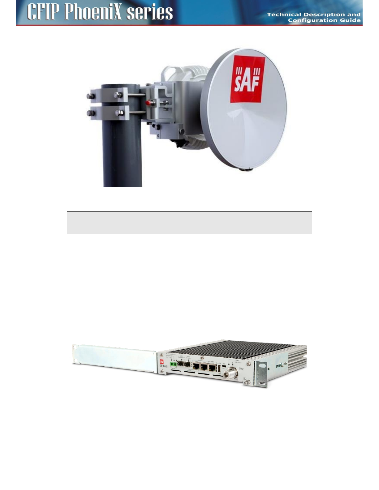
47
CFIP PhoeniX C Series TDM/IP Split Mount System Technical Description and Configuration Guide • Rev. 1.0 •
© SAF Tehnika JSC 2013
Figure 24: Final ODU and antenna installation
ATTENTION: Always fasten 2 latches which are against each other at the same time. Make sure that
the adapter slot and ODU waveguide slot match during the installation or while changing the
polarization.
IDU installation
CFIP Phoenix C IDU format was designed in accordance with mounting requirements for standard 19"
rack cabinet so that it occupies the least possible hight. The result is 1U height and ½ width of the
standard 19" rack position. Therefore you are able to put 2 IDUs alongside each other into 1 rack slot.
Both the devices are then connected with a special “Dual IDU mount kit” (optional accessory). The
depth of the unit's position towards 19" rack cabinet could be then changed just by shifting the
brackets holding the IDUs in their slots. Mounting the brackets for installing IDU into 19" cabinet:
– One IDU in one slot of 19" cabinet – 1x short and 1x long bracket, both brackets are included in
standard IDU delivery (Figure 25).
Figure 25: 1x IDU in 1U 19" cabinet
– Two IDUs in one slot of 19" cabinet – 2x short brackets, 1x Dual IDU mount kit. Use short
brackets from each IDU standard delivery, Dual IDU mount kit is an optional accessory
(Figure 26).
Page 48

48
CFIP PhoeniX C Series TDM/IP Split Mount System Technical Description and Configuration Guide • Rev. 1.0 •
© SAF Tehnika JSC 2013
Figure 26: 2x IDU in 1U 19" cabinet
ATTENTION: Do not forget to ground the CFIP Phoenix C Indoor unit with the grounding screw
located on the front panel of the IDU to the rack cabinet by means of Grounding kit (Grounding kit is
included in the standard IDU delivery package).
Cabling installation
IDU - ODU interconnection
Low-loss coaxial cable with a specified impedance of 50 Ohm which is terminated on both sides with
the N connectors serves for IDU and ODU units interconnection. Some examples could be the coaxial
cable marked as RG-213 and LMR-400. The assumed length of those cables in use between IDU and
ODU is 100 m for RG-213 and 300 m for LMR-400 in maximum. Recommended cables are listed in
chapter IDU-ODU cable on page 43.
ATTENTION: It is necessary to check the cable impedance or even better to measure the cable
impedance matching before interconnecting the ODU and the IDU with the cable.
Connecting of management interfaces
Use management Ethernet cable (included in standard IDU delivery) or management USB-B cable (not
in standard IDU delivery).
After connecting the management Ethernet cable into the port LAN 3 on IDU front panel, it is possible
to perform the primary configuration of microwave link and subsequently the management of the
entire system.
Or connect the management USB cable (USB A – computer side / USB B – IDU side) into the port
marked MNG / USB B (used primary for local management).
Connecting power supply
The device is powered from a DC source -48 VDC where the positive pole is grounded. Before
powering up the system do not forget to properly ground the ODU unit through the grounding screw
to the antenna mast to which it is attached. Similarly, properly ground the IDU unit to the rack cabinet.
Figure 27: DC connector pinout for IDU
Page 49
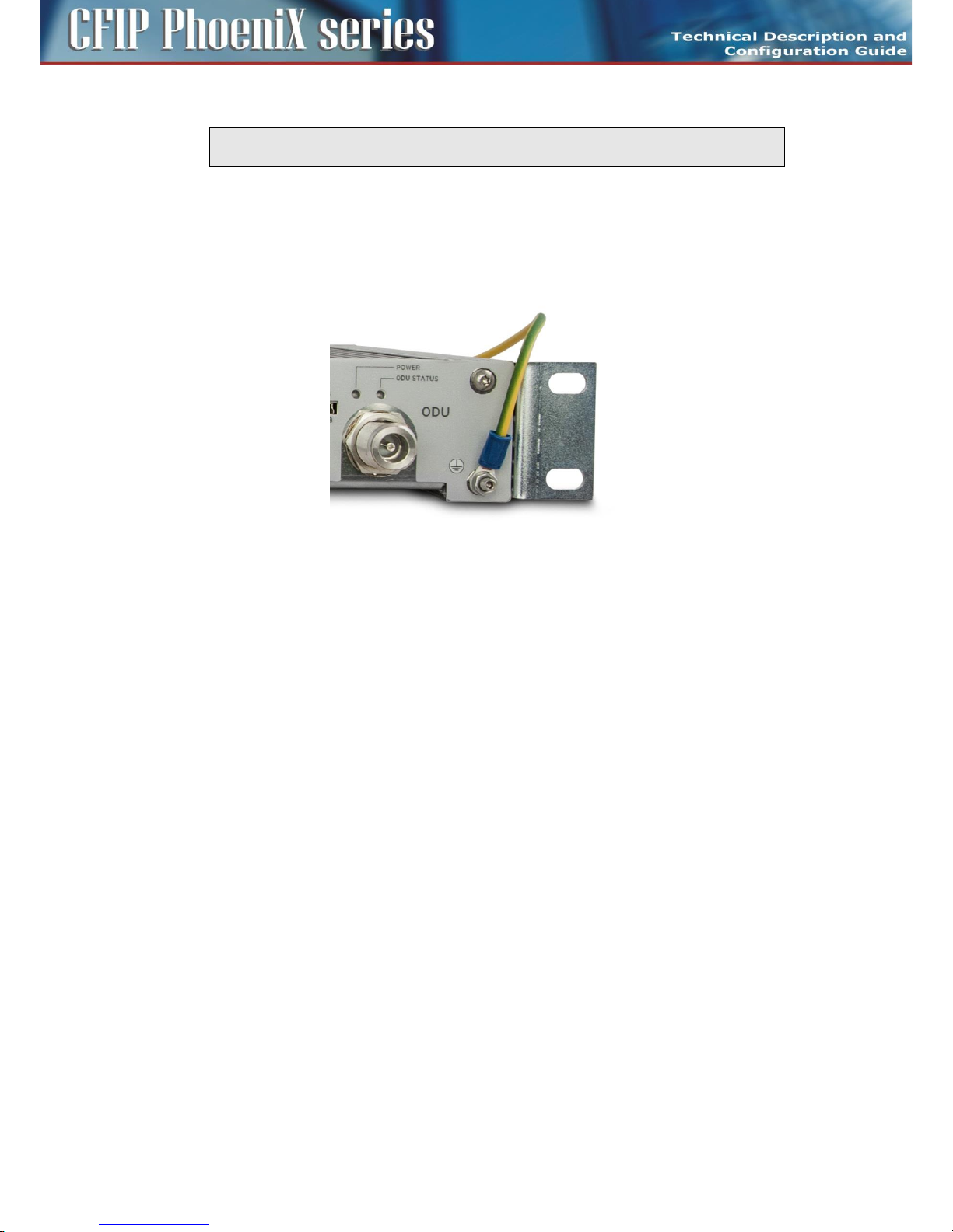
49
CFIP PhoeniX C Series TDM/IP Split Mount System Technical Description and Configuration Guide • Rev. 1.0 •
© SAF Tehnika JSC 2013
ATTENTION: Pay close attention to the correct power supply pinout polarity. Power Supply
pole 0 VDC is ever internally grounded inside IDU!
Grounding
For reliable and safe function of the whole system a proper IDU and ODU grounding is necessary.
Grounding cable for IDU is a standard part of accessories, which are packed together with IDU in
shipping box. Example of IDU grounding is in Figure 28. The grounding of ODU is provided by means of
grounding screw (M8) which is showed in Figure 13.
Figure 28: IDU grounding
Powering up the system
After careful checking of the coaxial cable installation (between IDU - ODU) and careful units
grounding proceed to the IDU powering up. It is necessary to wait about 20 seconds before the IDU
gets into normal operating state after its powering up. When the device is starting up watch the
system status diodes POWER, SYNC, LOCAL STATUS, REMOTE STATUS and ODU STATUS.
Standard system LED behaviour during start-up process
– POWER LED should light after power up.
– All system LED should be off for a period of about 10 seconds after power up.
– All system LED should light for a period of about 4 seconds after previous state.
– All system LED should flash-up for a period of about 3 seconds after previous state.
– Normal LED function then indicates current system state. Following status of system LED
indicates correct initial start-up.
- POWER lights
- SYNC is off
- LOCAL STATUS is flashing-up
- REMOTE STATUS is off
- ODU STATUS lights
We can proceed to the initial link configuration and antennas alignment when the IDU starts up.
Preparing for link configuration
For the initial configuration, use PC with Ethernet interface or with the USB port (for introduction see
chapter Cabling installation on page 38).
Page 50

50
CFIP PhoeniX C Series TDM/IP Split Mount System Technical Description and Configuration Guide • Rev. 1.0 •
© SAF Tehnika JSC 2013
PC setup with LAN adapter
In the case you are using management Ethernet cable for initial configuration you must first set your
computer IP address from the range which corresponds to the default IDU factory setup. By default
each IDU has from the factory the same IP address for ETH port (secondary IP address).
Default IDU ETH IP settings
IP address 10.10.10.10, net-mask 255.255.255.0
Therefore it is necessary to set the PC address in the range of 10.10.10.1-254, except for the device
own IP address (10.10.10.10). We recommend to set the computer as follows:
Computer LAN adapter settings
IP address 10.10.10.1, net-mask 255.255.255.0
Follow with the next step described in the figure below for computer IP settings.
Figure 29: PC IP LAN setup – local network connection
Page 51
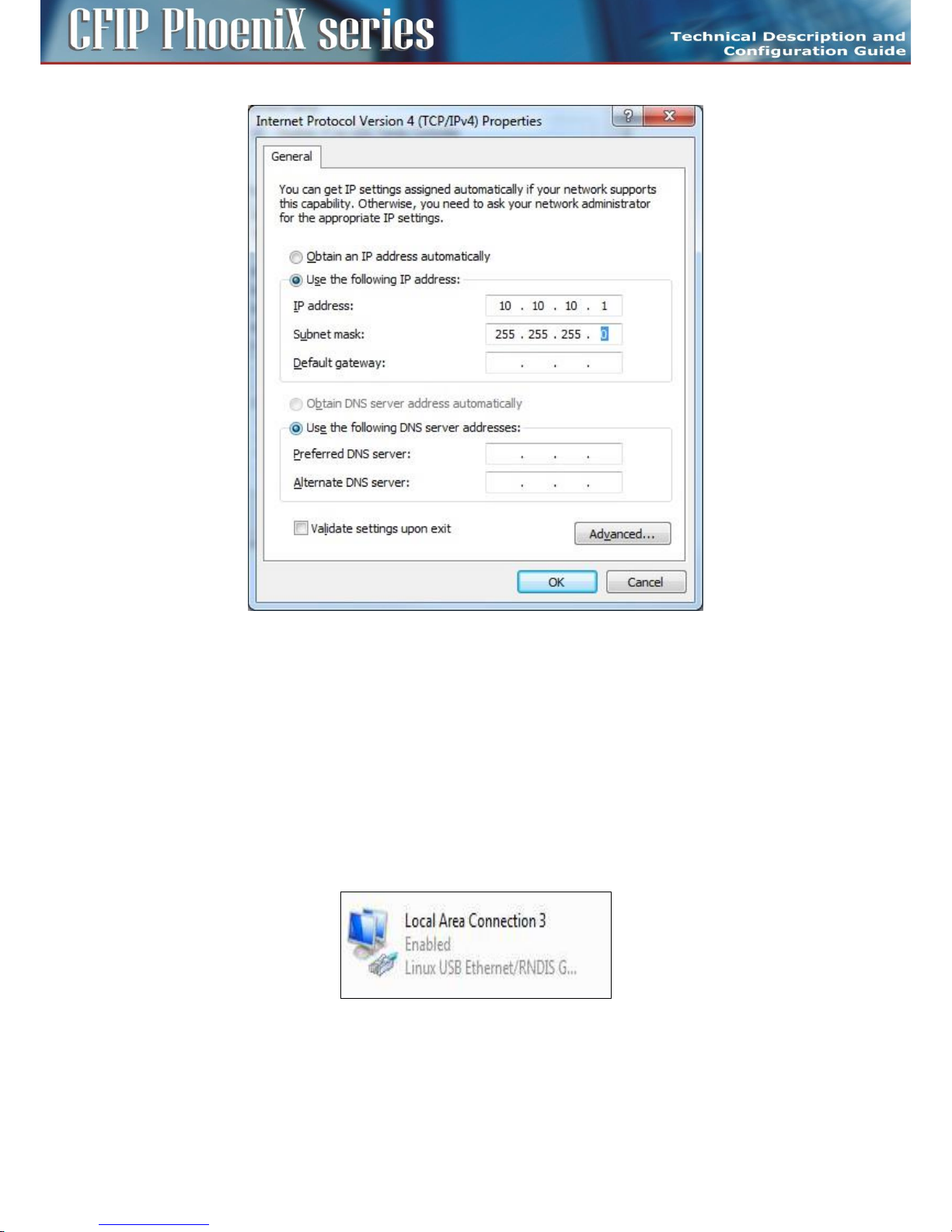
51
CFIP PhoeniX C Series TDM/IP Split Mount System Technical Description and Configuration Guide • Rev. 1.0 •
© SAF Tehnika JSC 2013
Figure 30: PC IP LAN setup – Internet protocol
PC setup with USB adapter
In the case you are using management USB cable for initial configuration you must first install USB/IP
driver on your computer with MS Windows OS (Linux based OS doesn't require additional driver
installation).
Follow the steps described in paragraphs below
– Connect the IDU to your computer (USB type A / USB type B cable is required).
– Wait for Windows driver installer prompt and select appropriate driver file (usb-gadget-eth.inf).
Ask producer´s representative for driver file before the installation process.
– Follow the instructions of your OS.
– After such installation the USB connection will be identified as an additional network adapter.
Figure 31: PC IP USB setup – USB network adapter
It necessary to assign correct IP address to your USB network adapter after proper driver installation.
By default each IDU has from the factory the same IP address for USB port (USB IP address).
Page 52

52
CFIP PhoeniX C Series TDM/IP Split Mount System Technical Description and Configuration Guide • Rev. 1.0 •
© SAF Tehnika JSC 2013
Default IDU USB IP settings
IP address 10.10.11.10, net-mask 255.255.255.0
Therefore it is necessary to set the PC address in the range of 10.10.11.1 – 254, except for the device
own IP address (10.10.11.10). We recommend to set the computer as follows:
Computer USB adapter settings
IP address 10.10.11.1, net-mask 255.255.255.0
Follow the similar steps described for LAN adapter configuration above, just select USB adapter
instead of LAN adapter.
Basic link set up
It is necessary to proceed with the basic link settings only once the mechanical link installation is done
so that you can align the antennas and test the connection functionality in a short test.
Login
First of all, connect with the web browser to the local IDU (via Ethernet or USB cable) typing
10.10.10.10 or alternatively 10.10.11.10 address into the web address bar (Mozilla Firefox version
3.xx and higher is recommended, IE 5 and above or OPERA 9.xx and above are also possible).
The IDU login window appears as in Figure 32. There you must insert:
Login "admin"
Password "secret"
Figure 32: LOGIN window
Page 53

53
CFIP PhoeniX C Series TDM/IP Split Mount System Technical Description and Configuration Guide • Rev. 1.0 •
© SAF Tehnika JSC 2013
When incorrect Login name or Password are entered the warning message „incorrect login name or
password” will appear in the IDU login window.
GUI Basics
After a successful login into the management system a General fold of GUI appears. Basically the web
management window is divided into few essential sections as described in Figure 33.
Header Section
Basic link parameters are displayed in this top bar section. A content in this section is common to all
GUI pages.
Main Menu
Main folders are accessible from each GUI page.
Sub Menu
A specific sub menu folders are displayed for each Main Menu folder.
Auto-Refresh and Refresh buttons
The auto-refresh A button is available on specific GUI pages only. It enables the periodic automatic
page refresh. The refresh interval is defined with the time elapsed between pressing REFRESH button
and followed with the pressing of the A button. The REFRESH button is used for standard refreshing of
information on GUI page.
Figure 33: Overview of GUI window
Page 54

54
CFIP PhoeniX C Series TDM/IP Split Mount System Technical Description and Configuration Guide • Rev. 1.0 •
© SAF Tehnika JSC 2013
IP setting
Figure 34: IP address configuration – GUI page “IP / Address
It is recommended to enter basic IP configuration of local and remote units (IDUs) at the very
beginning. This step is necessary for proper communication between local and remote side and
optionally for ensuring remote access to IDU devices from customer´s network. In our example we use
basic type of out-of-band management access (factory default configuration). Our examples suppose
that remote IP access will be provided from the direction of LOCATION1_M. For this mode we have set
following IP addresses:
For link site with name LOCATION1_M
Primary IP / Mask = 192.168.3.201/24
Default Gateway IP = 192.168.3.1
Remote Unit IP = 192.168.3.211
For opposite link site with name LOCATION2_M
Primary IP / Mask = 192.168.3.211/24
Default Gateway IP = 192.168.3.201
Remote Unit IP = 192.168.3.201
The remote device (IDU) must have equal IP addresses (primary IP and remote IP) set vice-versa.
Select in your web browser menu „IP / Address” (Figure 34). Enter the above assigned primary IP
address / net-mask, default gateway IP address and IP address of remote IDU on both sites. Confirm
entered values by pressing APPLY button.
NOTE: It is necessary to assign just correct Primary IP and Remote Unit IP addresses for installation
purposes. Informations from remote units cannot be displayed when this step is skipped. Next IP
settings can be applied during complete link configuration.
Page 55

55
CFIP PhoeniX C Series TDM/IP Split Mount System Technical Description and Configuration Guide • Rev. 1.0 •
© SAF Tehnika JSC 2013
For applying any IP configuration into the running system it is necessary to subsequently confirm IP
settings with pressing Write And Apply button in confirmation window (Figure 35). Without this
confirmation just IP temporary file is changed, but IP changes aren't applied into the running system
yet.
Figure 35: IP setting confirmation
Basic radio settings
Further it is necessary to set the basic radio parameters which will be used for the final completion of
the link installation. According to the Telecommunication Authority allocated parameters (Tx
frequency, Tx power) and requested data throughput we set the microwave link into a functional
configuration.
In our example – for link site with name LOCATION1
TX Frequency = 14580 MHz - set assigned Tx frequency for the Low Subband
Tx Power Limit = 3dBm - set the required maximum output power
ATPC = off - turn off the ATPC (must be off during the installation)
ODU TX Mute Config = auto - unmuted output power
Modulation Limit = 256_56000_01 - set the modulation to the most sensitive in assigned BW (56MHz
in our case)
ACM = off - adaptive modulation function should be off
In our example – for opposite link site with name LOCATION2
TX Frequency = 15000 MHz - set assigned Tx frequency for the High Subband
Tx Power Limit = 3dBm - set the required maximum output power
ATPC = off - turn off the ATPC (must be off during the installation)
ODU TX Mute Config = auto - unmuted output power
Modulation Limit = 256_56000_01 - set the modulation to the most sensitive in assigned BW (56MHz
in our case)
ACM = off - adaptive modulation function should be off
Page 56

56
CFIP PhoeniX C Series TDM/IP Split Mount System Technical Description and Configuration Guide • Rev. 1.0 •
© SAF Tehnika JSC 2013
Figure 36: Radio parameters setting – GUI page “Radio / Parameters
Set all the other parameters as depicted in the Figure 36 and confirm them with APPLY button.
Then save this new configuration into start-up memory with the button WRITE at the top of GUI page.
Configure the opposite side in the same way.
ATTENTION: Do not forget to save the configuration with WRITE button.
Antenna alignment
Antenna alignment is performed with both terminals operating in normal weather conditions.
Aligning the antenna is performed in both horizontal and vertical direction using a DC voltmeter. The
highest is the measured voltage, the highest is the received signal level. The voltage level is measured
directly on the output BNC connector (Figure 37) on the microwave ODU (RSSI – Received Signal
Strength Indication). It is recommended to use an appropriate BNC reduction.
Figure 37: Pinout of RSSI connector on ODU
Typical Received Signal Level Voltage for licensed bands is described in Figure 38.
Page 57

57
CFIP PhoeniX C Series TDM/IP Split Mount System Technical Description and Configuration Guide • Rev. 1.0 •
© SAF Tehnika JSC 2013
Figure 38: Curve of dependence RSL [dBm] on RSSI voltage [V]
Antenna alignment might be performed only in favourable weather conditions. Adverse weather
conditions are considered to be e.g. the rain, fog, snow, smog, etc. when the value of the measured
signal varies significantly, and so the measurement is very inaccurate!
NOTE: When aligning the antennas watch out for the possibility of "false" alignment on the side
lobes from remote antenna. It is important to identify main antenna lobe, by rotating the antenna
to have the maximum RSL voltage. The value of RSL should always correspond to the expected
calculated value of received signal strength.
Figure 41: Bad alignment Figure 42: Good alignment
The functional test
Before connecting the user's ports and the link commissioning it is recommended to do a quick test of
the basic device functions to verify proper microwave link installation and its error-free condition. For
that, it is again necessary to connect your PC and check the basic radio parameters.
Page 58
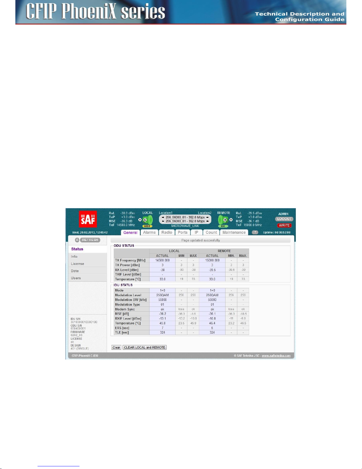
58
CFIP PhoeniX C Series TDM/IP Split Mount System Technical Description and Configuration Guide • Rev. 1.0 •
© SAF Tehnika JSC 2013
Obtaining the basic link information
Connect your PC according to the procedure described above and use „General / Status” page for
obtaining the required information (Figure 43).
– Tx Power – The figure should have a value corresponding to the assignment from
Telecommunication Authority.
– Rx Level – The figure should be in the range of -35 to -60 dBm and should correspond to the
expected level resulted from preliminary link calculation (tolerance + / - 3 dBm). Approximately
the same value (+ / - 3 dBm) should be measured also on the opposite site as well.
– MSE – Data should be in the range of -40 (better) to -30 dB (worse)
– Modem sync – The synchronization status of the modem part
MSE parameter indicates quality of received signal. The MSE (mean square error) parameter refers to
the average of the squared difference between the actual received symbols and the idealised points.
The closer the points are in the state diagram the better. Displayed MSE value is normalised type of
MSE parameter.
The values of MSE thresholds for each modulation is presented in the Technical Specification
document.
The same evaluation needs to be done on the other terminal too. If the icon of the opposite terminal
is not green (in the header of local terminal) it is not a problem now because it has not been made a
final adjustment of all the microwave link parameters yet.
Figure 43: Main microwave link parameters – GUI page “General / Status
If the measured values do not match the above stated ranges, it will be necessary to do a detailed
control of the link adjustment.
Five minute link quality measurement (optional)
The next step is a five minute measurement test of the microwave link. The real required
scheme should be configured (according to chapter Figure 35: IP setting confirmation
Basic radio settings on page 55) and MSE level must be checked again before such test.
Page 59
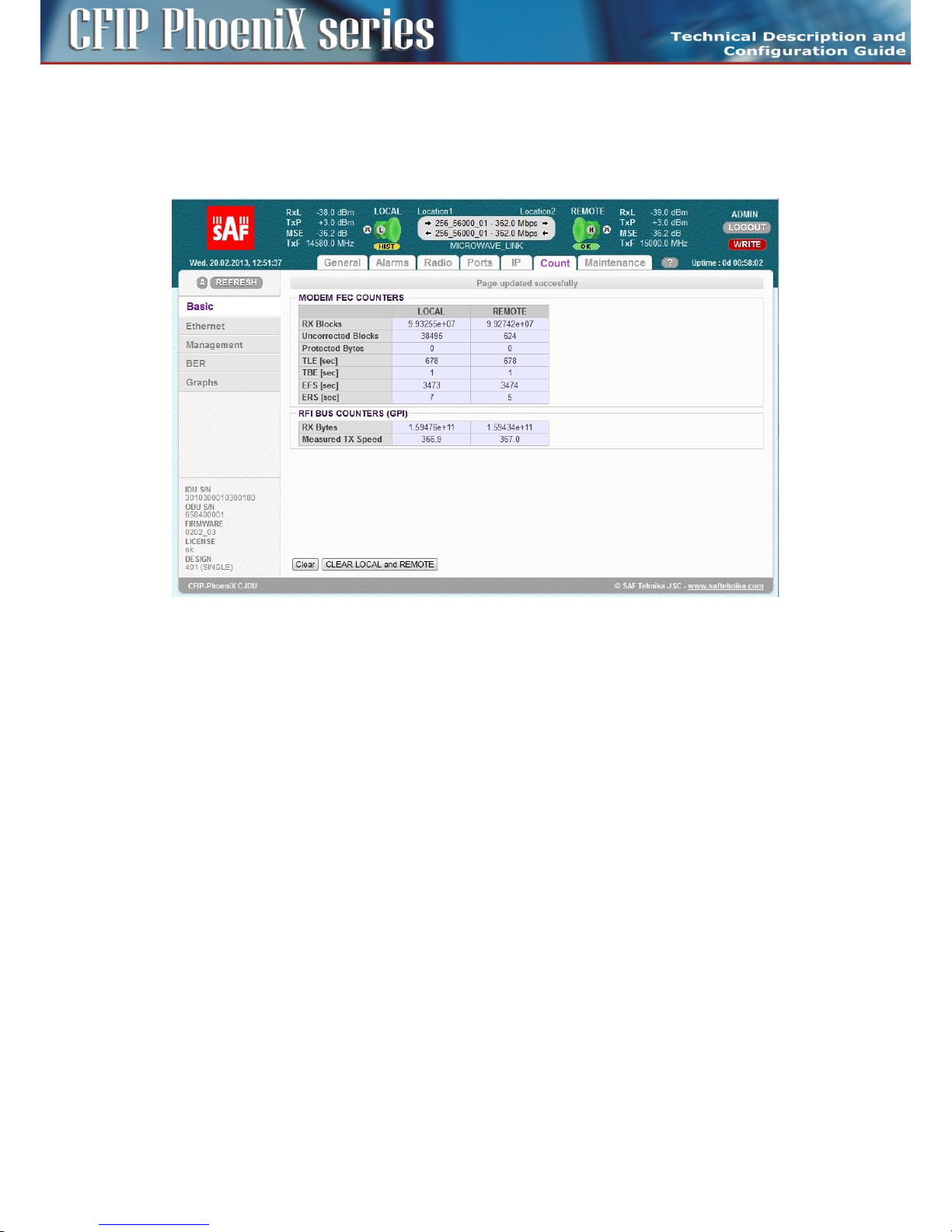
59
CFIP PhoeniX C Series TDM/IP Split Mount System Technical Description and Configuration Guide • Rev. 1.0 •
© SAF Tehnika JSC 2013
When updated configuration is done and MSE level stands with expected level, press button CLEAR
LOCAL and REMOTE on page „General / Status”. Then go to the page „Count / Basic” to see the link
statistics after about 5 minutes.
The result is then depicted in the Figure 44 below. To perform this test there is no need to have any
data connection into LAN ports.
Figure 44: Basic radio link statistics – GUI page “Count / Basic”
– RX Blocks – The number of correctly received air frames, large number.
– Uncorrected Blocks – The number of frames which couldn't be corrected by FEC; the figure
should be „0”.
– Protected Bytes – Important just for protection mode, the figure should be „0”.
– TLE – Time since last error; number of seconds from last error occurrence. It should correspond
to the time since pressing the button CLEAR LOCAL and REMOTE on the main page
„General / Status” and it should be the same as EFS value.
– TBE – Time between last two error events, the figure should be „0”.
– EFS – Error free seconds; it should correspond to the time since pressing the button CLEAR LOCAL
and REMOTE on the main page „General / Status”.
– ERS – Error seconds; number of seconds during which the errors occurred; the figure should be
“0”.
If test results are different compared to expected values, you have to perform a detailed check of the
microwave link installation. Similar results must be read out on the opposite terminal of the link as
well or from column marked REMOTE.
Connection of external equipment
Microwave system CFIP Phoenix C is equipped with Gigabit Ethernet ports. At the same time it is
possible to insert the standard SFP modules into the free SFP slots which allow to connect external
modules EMM or additional Gigabit Ethernet equipment.
Page 60

60
CFIP PhoeniX C Series TDM/IP Split Mount System Technical Description and Configuration Guide • Rev. 1.0 •
© SAF Tehnika JSC 2013
Connecting Gigabit Ethernet port
Gigabit Ethernet 10/100/1000 Mbps port pinout is given in Figure 45. The user has to make sure that
all the four pairs of the cable according to required pinout are wired.
Figure 45: Gigabit Ethernet port pinout
Pin 1 - DA+, Pin 2 - DAPin 3 - DB+, Pin 6 - DBPin 4 - DC+, Pin 5 - DC-
Pin 6 - DD+, Pin 7 – DD-
ATTENTION: It is necessary to prevent any possible Ethernet loops before connecting the
Ethernet cable to the Gigabit Ethernet ports. Therefore correct Ports setting must be carried
out before more than one Ethernet cable is inserted into IDU.
Connecting the external EMM module via port SFP 2
Depending on the customer´s application the number of IDU ports can be extended by means of
specific external multiplexer module (EMM). The EMM-16E1T1 is mostly connected into the port SFP 2
of IDU by means of a Fiber Optic cable.
IDU and also EMM module must be then equipped with SFP module for connecting the Fiber Optic
cable.
The SFP module should be inserted before IDU power-up, but can be plugged also when system is
under power. Appropriate Fiber Optic cable with LC connectors must be used for CFIP Phoenix C IDU
and EMM interconnection (usually 0.5 m long cable is adequate).
Page 61

61
CFIP PhoeniX C Series TDM/IP Split Mount System Technical Description and Configuration Guide • Rev. 1.0 •
© SAF Tehnika JSC 2013
Chapter 4 – Link Configuration
Introduction
After the installation of the microwave link itself it is necessary to carry out the complete set-up of all
the required link parameters including IP management settings. It is recommended to write these
parameters such as IP addresses, Tx frequency, Tx power, etc. in advance into a well-arranged table.
Save this data list, in a case of a later replacement of a unit, previous configuration can be restored
easily.
Further we will continue with description of the link set-up from a web interface. The link set-up using
text commands is not part of this manual.
ATTENTION: Do not use the browser functions „back” and „page refresh” during the set-up or for
view of the previous window. Use only the Main menu and submenu folders and GUI buttons of
CFIP Phoenix C IDU device.
Connection and Login
The local access over Ethernet LAN interface
For the IDU set-up via a management LAN port (LAN 3 by default) there is only required a connection
between PC and port LAN 3 on IDU front panel with the proper Ethernet cable. This process was
described in section PC setup with LAN adapter on page 50.
The local access over USB-B interface
For the IDU set-up via a USB port there is only required a connection between PC and USB-B port on
IDU front panel with the proper USB cable. This process was described in section PC setup with USB
adapter on page 51.
LOGIN from the Web browser
Before connecting the Ethernet management cable into the port LAN 3 or a USB management cable
into port USB B at the IDU it is necessary to configure the computer's network connection.
The CFIPPhoenix C IDU comprises of
– the secondary IP address for access via LAN port, which is set by manufacturer to default value
10.10.10.10/24 with the network mask 255.255.255.0
– the USB IP address for access via USB port, which is set by manufacturer to default value
10.10.11.10/24 with the network mask 255.255.255.0
After proper configuration of the computer's network connection a Web browser could be launched.
Enter the secondary IP address of the CFIP Phoenix C IDU, that is 10.10.10.10 into the address bar of
the Web browser (example for connection over LAN 3 port). After entering this address, the login
window appears, see Figure 32.
The login into the device is active until the logout of the device is performed. Thus it is not possible to
configure the IDU from two terminals at the same time (only one terminal could be in the set-up
mode at one moment). It means just one user with User or Administrator rights can be logged in.
There is an automatic timeout in the device – after period of 10 minutes from the last action (in the
Web environment) any user is automatically logged out.
Page 62
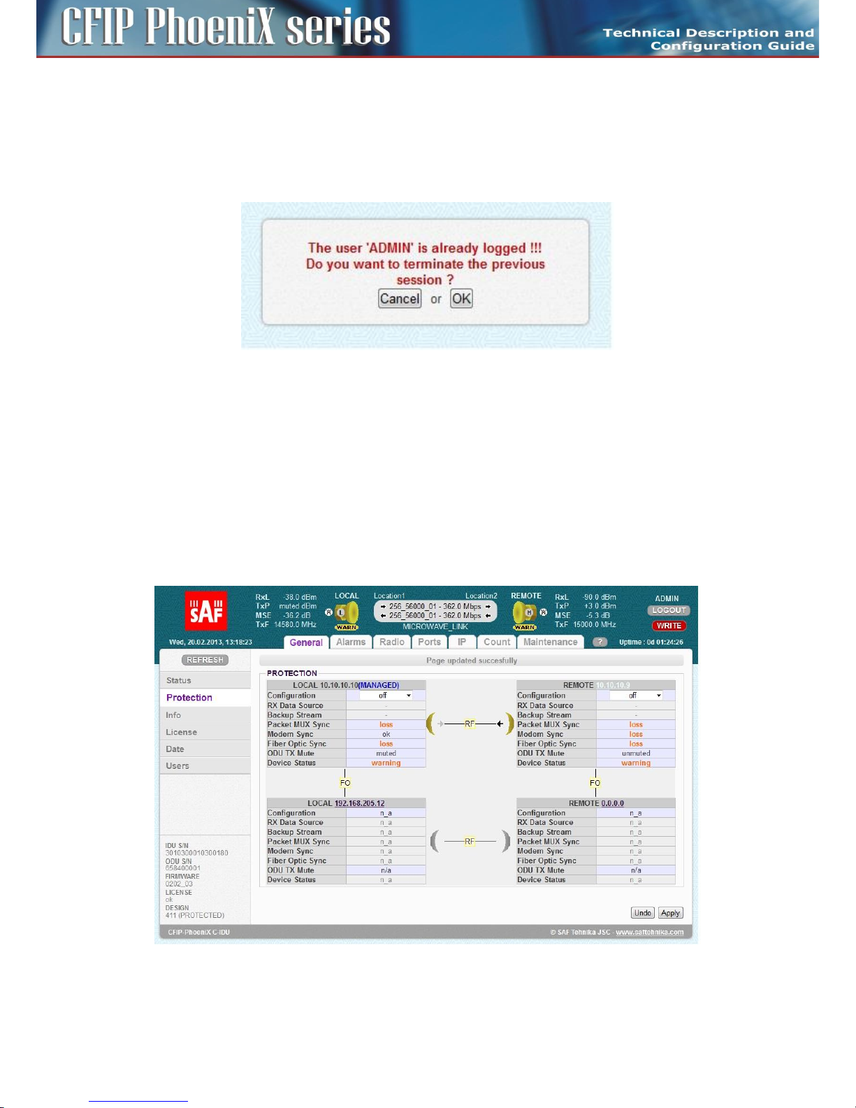
62
CFIP PhoeniX C Series TDM/IP Split Mount System Technical Description and Configuration Guide • Rev. 1.0 •
© SAF Tehnika JSC 2013
For the standard configuration we recommend to login in the USER mode.
Administrator level is superior to the User level. When the Administrator tries to login the system and
the User is already in the system, an alert window asks if the Administrator wants to logout the User,
because there may be logged only one of them at one moment, see Figure 46.
Figure 46: Alert window about already logged User
The rights and options for each access mode are described in more details in the chapter Access Rights
on page 67.
General system configurations
Protection scheme setting
Availability of „Protection” settings page depends primarily on selected design type and available
license content. See the chapter Advanced system configuration on page 97. When Protected 1+1
design is selected and the same design is supported in license file, then general protection settings are
managed from GUI page „General / Protection” (Figure 47).
Figure 47: Initial Protection configuration– GUI page „General / Protection
By default the protection mode is „off” after a change into this design. This prevents any possible
Page 63

63
CFIP PhoeniX C Series TDM/IP Split Mount System Technical Description and Configuration Guide • Rev. 1.0 •
© SAF Tehnika JSC 2013
setting mistakes like radio interferences, port loopbacks etc. TxPower is muted and all traffic ports are
down in „Protection off” mode.
NOTE: Customer should set all Radio, IP and Port parameters according to prepared system
configuration and configure protection mode as the last step in system configuration procedure.
The graphical antenna icons (-RF-) on this GUI page help to understand actual state of IDU, the state of
the whole protected link (green – no alarm) and the mode of appropriate ODU transmitter (black
arrow indicates that transmitter is unmuted, number of arrows indicates TX mode – FD/SD+HSB).
The description of particular setting and display boxes
– Configuration – This drop-down menu shows and selects actual / configured protection mode. It
is recommended to ensure the correct system interconnection at both remote and neighbor
units at first and then set the required protection mode at MASTER SIDE. Slave side will be
configured automatically.
The possible modes are:
- master/FD, slave/FD – This mode configures frequency diversity mode when two
transmitters and two receivers operate on different carrier frequencies but identical to the
corresponding transmitter at the far end. This protection mode protects against Multipath
Fadding and also against PtP system HW failure.
- master/SD, slave/SD – This mode configures space diversity mode when one transmitter is
used (customer can select manually transmitter at master or slave unit) and two receivers
operate on just one carrier frequency. Two antennas at each installation side should be
used. When both master and slave units are without receive signal or without
synchronization, opposite transmitter side stays without change. This protection mode
usually protects against Multipath Fadding.
- master/HSB, slave/HSB – This mode configures hot standby protection mode when one
transmitter is used at actual time (customer can select manually transmitter at master or
slave unit) and two receivers operate on just one carrier frequency. One antenna with
directional coupler at each installation side should be used. When both master and slave
units are without receive signal or without synchronization, opposite transmitters are
swapped (actual one is muted and second one is unmuted) to ensure correct system
function. This protection mode protects against PtP system HW failure. Protection is hitless
for Rx failures, when transmitters are swapped, then short drop in traffic occurs.
– RX Data Source – This box displays what a traffic stream either from master link (main) or slave
link (backup) is actually running on master unit.
– Backup Stream – This box displays that main and backup streams are aligned at master unit
during normal system function. Aligned status must be shown when master Modem is synced.
When master IDU is without Modem sync, then this status doesn't have a relevant meaning.
– Packet MUX Sync – This box displays actual Packet MUX synchronization at master and slave
unit. Packet MUX synchronization at master side must be „ok” during correct protection
operation, even if the master IDU's modem sync is lost.
– Fiber Optic Sync – This parameter shows actual Fiber Optic interconnection status between
master and slave unit.
– ODU TX Mute – Muted or unmuted status indicates whether appropriate ODU transmitter is
active (unmuted) or in standby/nonfunctional mode (muted).
– Device Status – This value shows alarm status of appropriate units.
Page 64

64
CFIP PhoeniX C Series TDM/IP Split Mount System Technical Description and Configuration Guide • Rev. 1.0 •
© SAF Tehnika JSC 2013
Aggregation scheme settings
Availability of „Aggregation” settings page depends primarily on selected design type and available
license key. Check Advanced system configuration chapter at page 97. When Aggregate 2+0 design is
selected and the same design is supported in license file, then the general aggregation configuration
can be managed from the GUI page „General / Aggregation” (Figure 48).
Figure 48: Initial Aggregation configuration – GUI page „General / Aggregation
By default the aggregation mode is „off” after a change into this design. This default selection
prevents any possible settings mistakes like radio interferences, port loopbacks etc.
NOTE: Customer should set all Radio, IP and Port parameters according to prepared system
configuration and configure aggregation mode as the last step in system configuration procedure.
The graphical antenna icons (-RF-) on this GUI page help to understand actual IDU and whole link state
(green – no alarm).
The description of particular setting and display boxes
– Configuration – This drop-down menu shows and selects actual / configured aggregation mode.
It is recommended to ensure correct system interconnection at both remote and neighbor units
at first and then set the required aggregation mode at MASTER SIDE. Slave side will be configured
automatically.
The possible modes are:
– master/2+0 – This selection configures master mode for aggregation scheme, when two
transmitters and two receivers operate on two different carrier frequencies. It is possible to use
also cross-polar configuration in a specific case for aggregation scheme (contact local
representative for more details). This aggregation mode controls aggregation process on both
units.
- slave/2+0 – This selection configures slave mode for aggregation scheme. This aggregation
mode uses the highest priority channel ETH 4 for data transmission over slave link.
Page 65

65
CFIP PhoeniX C Series TDM/IP Split Mount System Technical Description and Configuration Guide • Rev. 1.0 •
© SAF Tehnika JSC 2013
- off – This item (mode) disables aggregation function. The function in this mode is similar to
function of design MULTI but with just three channels over air.
– TX Aggreg Mode – This drop-down menu sets the specific Tx aggregation modes. The possible
modes are:
- auto – TX data stream is automatically divided into two links according to momentary
available capacity of each link.
- master only – Aggregation is disabled in this mode. TX data stream is manually directed to
master link only.
- slave only – Aggregation is disabled in this mode. TX data stream is manually directed to
slave link only.
– TX Aggreg Status – This box shows actual TX status which is especially important for auto
aggregation mode. In this mode the aggregation block automatically decides what direction will
be used for Tx data transmission:
- aggregate – Data are transferred over both links (normal mode).
- master only – Data are transferred over master link (slave link is down or in some trouble
or mode is manually set to master only).
- slave only – Data are transferred over slave link (master link is down or in some trouble or
mode is manually set to slave only).
– RX Aggreg Mode – This box displays status of receiving part in an aggregation block:
- ok – Receiving block operates properly, both traffic directions are aligned.
- alignment drops – Incorrect order of packet is detected at receiving side, this status
indicates abnormal packet delay at master or slave link.
- packet discards – This status indicates packet losses at master or slave link.
– Packet MUX Sync – This box displays actual Packet MUX synchronization at master and slave
unit.
– Fiber Optic Sync – This parameter shows actual Fiber Optic interconnection status between
master and slave unit.
– Device Status – This value shows alarm status of relevant unit.
Basic Link Info
It is recommended to fill-in the table with complete link identification. This will be helpful for next
system description. Such configuration is accessible from WEB GUI page „General / Info” in Figure 49.
Page 66

66
CFIP PhoeniX C Series TDM/IP Split Mount System Technical Description and Configuration Guide • Rev. 1.0 •
© SAF Tehnika JSC 2013
Figure 49: Wireless Link Info – GUI page „General / Info”
There is displayed basic system identification information like IDU/ODU Serial Numbers, Product
Numbers, Firmware Specification etc. in the same page.
The description of particular setting and display boxes
– Device Name – This text is displayed in the GUI header for identification of the unit. The same
name is used as a prompt in CLI. Maximal length is 13 characters.
– Page Header – This text is used in the WEB browser bookmark for better identification what unit
is actually managed. Maximal length is 25 characters.
– Link Name – This text is displayed in GUI header for accurate identification of the managed link.
The same name should be entered at both sides of the microwave link. Maximal length is 25
characters.
– Custom Text – Up to four customer´s specific descriptions can be entered. Maximal length is 80
characters per row.
NOTE: All settings from this page are directly saved to a specific start-up memory which is common
for all alternative configurations W0-W3.
Date and Time
It is recommended to set accurate Date and Time information at all IDU units within the microwave
network. This will be helpful especially for alarm event and log analysis. The configuration is
accessible from GUI page „General / Date” in Figure 50.
Page 67

67
CFIP PhoeniX C Series TDM/IP Split Mount System Technical Description and Configuration Guide • Rev. 1.0 •
© SAF Tehnika JSC 2013
Figure 50: Date and Time specification – GUI page „General / Date”
The description of particular setting and display boxes
– Date – Specification of actual date.
– Time – Specification of actual time.
– Time Zone – Selection of a proper Time Zone from the drop-down menu.
– Fill-in PC time + 10s – With pressing this button an actual PC time increased by 10 seconds is
entered into Date and Time boxes. 10 second offset is used, because time setting is applied not
sooner than APPLY and SAVE button is pressed.
– Time Server – This setting is part of IP configuration, because it is activated together with other
IP parameters. When Time server option is selected, Date and Time are synchronized from
external source.
Access Rights
It is possible to monitor and manage the microwave link CFIP Phoenix C after the login into the system
only, both locally and remotely. In dependence on the login level (after entering a Login and a
Password) the relevant access rights are automatically granted to the user, which affect the scope of
the management capabilities for the microwave link. These login levels must be respected both in
access from web interface as well as from a Telnet, SSH or SNMP connections.
It is strictly recommended to change default login names and passwords for access into managed
networks. Such configuration is accessible from WEB GUI page „General / Users” (Figure 51).
Page 68

68
CFIP PhoeniX C Series TDM/IP Split Mount System Technical Description and Configuration Guide • Rev. 1.0 •
© SAF Tehnika JSC 2013
Figure 51: Access levels setting – GUI page „General / Users”
Each of the three possible login modes has different rights for the system management. The following
Logins and Passwords are default from the production:
Guest
Login with a user name guest and a password „blank” (no character, enter only).
In this basic user mode, it is possible to monitor the traffic on the microwave link, monitor the qua lity
of the frequency tuning, read out the values from the equipment (TxPower, etc.), clear some counters
etc. Up to 3 users in maximum of the Guest level can be logged in the system at the same time.
User
Login with a user name user and a password test.
The User has the same rights as the Guest user extended with the rights to configure and set the
microwave link parameters. Only one user with the rights User can be logged in the device at one
moment. At the same time up to three Guests can be in the system to monitor it.
When the User tries to log on the system and the Administrator is already in the system, an alert
window informs that „The user ADMIN is already logged”. The log in is not performed.
Administrator
Login with a user name admin and a password secret.
The Administrator has the same rights as Guest and User extended with the rights to upload new
firmware in the equipments, control the database of users and change the user names and the
passwords.
Administrator is superior to the User level. When the Administrator tries to log on the system and the
User is already in the system, an alert window asks if the Administrator wants to logout the User,
because there may be logged only one of them at one moment.
LOGIN NAME – 1-12 characters
PASSWORD – 1-15 characters
The valid characters are letters, numbers and special symbol “_”. Login names must be different for
Page 69

69
CFIP PhoeniX C Series TDM/IP Split Mount System Technical Description and Configuration Guide • Rev. 1.0 •
© SAF Tehnika JSC 2013
each access right group.
NOTE: All settings from this page are directly saved to a specific start-up memory which is common
for all alternative configurations W0-W3.
Alarms configurations
A proper alarm configuration helps to effectively solve potential troubleshooting events and/or
disclose any system instability. From the configuration point of view all the most important alarm
settings are available from GUI page „Alarms / Config&Status” (Figure 52).
Figure 52: Alarms setting – GUI page „Alarms / Config&Status”
Config&Status
This GUI page has the form of table where it is possible to configure the following modes:
– An activation of individual alarm ID which influences whole IDU status. Such activated alarm ID
will generate alarm events into internal alarm log file and SNMP trap message, if this feature is
configured in IP setting. When just one activated alarm ID is in the warning state, then the whole
IDU is in the warning status as well. It is represented with the yellow color of the local unit icon
at the top of each GUI page.
– The activation of alarm ID at both local and remote units from the one unit (from actually
managed unit).
– The set-up of a concrete alarm threshold values for a specific alarm IDs. Actual value is then
compared with such defined alarm threshold level values.
Page 70

70
CFIP PhoeniX C Series TDM/IP Split Mount System Technical Description and Configuration Guide • Rev. 1.0 •
© SAF Tehnika JSC 2013
It is also possible to check the status of alarms on the same GUI page
– Monitoring of actual alarm status of both active and also of inactive alarm IDs.
– Checking comparison values with configured but also with default defined thresholds.
– Checking detailed description for specific alarm ID reason.
Colored icons of each alarm help to quickly understand what is an actual status of the appropriate
alarm ID.
– Green icon
The icon indicates that the alarm ID is activated (monitored) and no alarm status is detected.
– Dark-green icon
The icon indicates that the alarm ID is not activated and no alarm status is detected.
– Yellow icon
The icon indicates that the alarm ID is activated (monitored) and the warning status is detected.
– Dark-yellow icon
The icon indicates that the alarm ID is not activated but a potential warning status is detected.
IDU system alarms
– License Alarm – ID 01.0.02 (critical)
This alarm ID indicates actual license status.
- No alarm = License OK.
- Warning = License is in blocked or remote_violation status.
– Protection Alarm – ID 01.0.03
This alarm ID indicates actual protection status.
- No alarm = Protection parameters (Rx Data Source and Backup Stream) are in normal status
(Rx Data Source=Main, Backup Stream=aligned).
- Warning = One or more protection parameters are in abnormal state.
– IDU HW Alarm – ID 01.0.04 (critical)
This alarm ID indicates actual status of IDU HW (hardware). Explicit reason for such HW alarm event is
then described in column „LOCAL DETAILS” in GUI.
- No alarm = all internal HW blocks work properly.
- Warning = one or more internal HW blocks indicate abnormal function.
– IDU SW Alarm – ID 01.0.05 (critical)
This alarm ID indicates actual status of IDU SW (software).
- No alarm = all internal SW blocks work properly.
- Warning = one or more internal SW blocks indicate abnormal function.
– IDU Temp Alarm – ID 01.0.06
This alarm ID indicates actual status of IDU temperature.
- No alarm = Actual temp. is in the range of -5 up to +60°C.
- Warning = Actual temp. is out of range of -5 up to +60°C.
IDU modem and mux alarms
– Modem Sync Alarm – ID 01.0.10 (critical)
This alarm ID indicates actual status of modem synchronization.
- No alarm = Modem synchronised.
- Warning = Modem sync loss.
– Modem FER Alarm – ID 01.0.11
This alarm ID indicates status of modem frame (air-frame) error rate in the last 60 seconds with
respect to the configured threshold.
- No alarm = Actual modem FER value is lower than the FER threshold defined in the same
Page 71

71
CFIP PhoeniX C Series TDM/IP Split Mount System Technical Description and Configuration Guide • Rev. 1.0 •
© SAF Tehnika JSC 2013
alarm row.
- Warning = Actual modem FER value is higher or equal to the FER threshold defined in the
same alarm row.
– MSE Level Alarm – ID 01.0.12
This alarm ID indicates actual modem MSE value in dB with respect to configured threshold.
- No alarm = Actual MSE value is lower than the MSE threshold defined in the same alarm
row.
- Warning = Actual MSE value is higher or equal to the MSE threshold defined in the same
alarm row.
– MUX Sync Alarm– ID 01.0.13 (critical)
This alarm ID indicates actual status of packet processor (PBPS) synchronization.
- No alarm = PBPS synchronised.
- Warning = PBPS sync loss.
– MUX FER Alarm – ID 01.0.14
This alarm ID indicates status of packet processor frame (PBPS frame) error rate in the last 60 seconds
with respect to configured threshold.
- No alarm = Actual PBPS FER value is lower than the FER threshold defined in the same
alarm row.
- Warning = Actual PBPS FER value is higher or equal to the FER threshold defined in the
same alarm row.
– IDU Cable Alarm – ID 01.0.15 (critical)
This alarm ID indicates actual status of IF level at the IDU input.
- No alarm = Actual IDU IF level (at 140MHz) is higher than -35dBm.
- Warning = Actual IDU IF level (at 140MHz) is lower or equal to -35dBm.
ODU alarms
– ODU Cable Alarm – ID 01.0.20 (critical)
This alarm ID indicates actual status of IF level at the ODU input.
- No alarm = Actual ODU IF level (at 350MHz) is in the specified range defined with
appropriate ODU type.
- Warning = Actual ODU IF level (at 350MHz) is out of the specified range defined with
appropriate ODU type.
– ODU RX Level Alarm – ID 01.0.21
This alarm ID indicates status of RF received level at the ODU receiver with respect to configured
threshold.
- No alarm = Actual ODU Rx Level is higher than the Rx Level threshold defined in the same
alarm row.
- Warning = Actual ODU Rx Level is lower or equal to the Rx Level threshold defined in the
same alarm row.
– ODU Mute Alarm – ID 01.0.22
This alarm ID indicates actual ODU Mute status.
- No alarm = ODU is unmuted (auto unmute).
- Warning = ODU is muted (auto mute or manual mute).
– ODU Temp Alarm – ID 01.0.23
This alarm ID indicates actual status of ODU temperature.
- No alarm = Actual temp. is in the range of -25 up to +60°C.
- Warning = Actual temp. is out of the range of -25 up to +60°C.
– ODU HW Alarm – ID 01.0.24 (critical)
This alarm ID indicates actual status of ODU HW (hardware). Explicit reason for such HW alarm event
is then described in the column „LOCAL DETAILS” in GUI.
- No alarm = all internal HW blocks work properly.
- Warning = one or more internal HW blocks indicate abnormal function.
Page 72

72
CFIP PhoeniX C Series TDM/IP Split Mount System Technical Description and Configuration Guide • Rev. 1.0 •
© SAF Tehnika JSC 2013
– ODU Comm Alarm – ID 01.0.25 (critical)
This alarm ID indicates incorrect or missing communication between the local IDU and the local ODU.
- No alarm = IDU-ODU communication is without losses.
- Warning = IDU-ODU communication failure.
Interface alarms
– LAN 1 Link Alarm – ID 01.0.32
This alarm ID indicates actual status of link at LAN 1 port.
- No alarm = Link OK condition at port LAN 1.
- Warning = NO Link at port LAN 1.
– LAN 2 Link Alarm – ID 01.0.33
This alarm ID indicates actual status of link at LAN 2 port.
- No alarm = Link OK condition at port LAN 21.
- Warning = NO Link at port LAN 2.
– LAN 3 Link Alarm – ID 01.0.34
This alarm ID indicates actual status of link at LAN 3 port.
- No alarm = Link OK condition at port LAN 3.
- Warning = NO Link at port LAN 3.
– SFP 1 Link Alarm – ID 01.0.36
This alarm ID indicates actual status of link at SFP 1 port.
- No alarm = Link OK condition at port SFP 1.
- Warning = NO Link at port SFP 1.
– SFP 2 Link Alarm – ID 01.0.37
This alarm ID indicates actual status of link at SFP 2 port.
- No alarm = Link OK condition at port SFP 2.
- Warning = NO Link at port SFP 2.
Radio configurations
Basic Radio settings
The basic Radio configuration is available from the GUI page „Radio / Parameters”. Parameters for
both local and also for remote unit can be set together in one configuration step when appropriate
boxes for local and remote unit are edited (Figure 53).
The configuration window is divided into three columns: LOCAL, REMOTE, LOCAL RANGE. The values in
LOCAL column are valid parameters for local unit, likewise, the values in column REMOTE are used for
remote side configuration (when communication with remote side is in operation). LOCAL RANGE
column states the range of applicable values, if such limitations exists for specific parameter.
Page 73
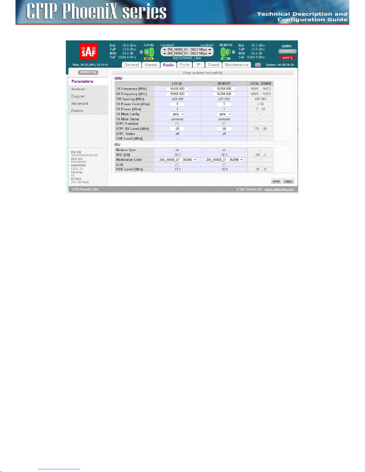
73
CFIP PhoeniX C Series TDM/IP Split Mount System Technical Description and Configuration Guide • Rev. 1.0 •
© SAF Tehnika JSC 2013
Figure 53: Radio parameters setting – GUI page „Radio / Parameters”
The description of particular setting and display boxes
– TX Frequency – Transmission frequency can be set within the displayed frequency range in
accordance with concrete ODU subband specification (read from the connected ODU). Such
displayed range is the edge to edge flat diplexer frequency scope and therefore respective Tx
Frequency value within that scope must be increased / decreased by one half of used
modulation bandwidth if that is near these edges.
– RX Frequency – Receive frequency is usually set automatically, because majority of ODUs
operate with the fixed T/R spacing. For specific ODUs, where RX Frequency can be set
independently, this value box can be filled-in by customer.
– T/R Spacing – TX / RX frequency distance is a real calculated value of this parameter. There is
displayed standard ODU T/R spacing in the column LOCAL RANGE.
– TX Power Limit – Maximum transmission power parameter defines the maximum power level
which is required for optimal transmission conditions. The operating TxPower then depends on:
- Configured ATPC values
- ODU limit which depends on the used RF band and selected modulation.
– TX Power – The output RF power level that is just transmitted of ODU. LOCAL RANGE column
displays the TX Power scope of used ODU under actual conditions (band, modulation).
– TX Mute Config – Transmitter mute configuration. Two modes of this parameter can be selected.
Mute mode is selected for fixed ODU mute configuration. Auto mute mode is a standard
selection for this parameter. In that case a ODU is automatically muted when abnormal
transmission conditions are detected by IDU or ODU:
- Initial TX Frequency is outside of available range,
- ODU cable alarm,
- Specific protection mode.
– TX Mute Status – Actual transmitter mute status.
– ATPC Function – Automatic Transmit Power Control enables or disables the ATPC feature. The
transmitted power is automatically adjusted to ensure that the optimum RxLevel (ATPC RxL) is
received at the remote terminal (hitless regulation).
Page 74

74
CFIP PhoeniX C Series TDM/IP Split Mount System Technical Description and Configuration Guide • Rev. 1.0 •
© SAF Tehnika JSC 2013
NOTE: The ATPC function should be always OFF during the installation!
– ATPC RX Level – Required level for Automatic Transmit Power Control. Field specifies the optimal
receive level used for ATPC function.
– ATPC Status – Status of ATPC loop.
- off – It indicates that ATPC function is disabled.
- ok – It indicates that ATPC loop has regulated required level.
- out of range – It indicates that ATPC loop cannot reach the required level.
– TXIF Level – Transmit IF level at ODU input (350 MHz) indicates the signal strength of IF input into
ODU. This level should be in the range of 0 dBm up to -30 dBm (low signal). By standard the
output TXIF level from IDU is 0 dBm. It is useful to check this value if that corresponds to
supposed cable attenuation.
– Modem Sync – Demodulator synchronization status is the basic indicator of proper function of
IDU receiver.
- ok – It indicates that demodulator is synchronised with received air-frame.
- loss – It indicates that demodulator is not synchronised with received air-frame.
– MSE – Mean Square Error is a basic quality of signal indicator. Used MSE value is normalized
presentation of MSE value. In absolute value it can be presented also as signal to noise ratio
when demodulated signal is close to sensitivity level. The lower the value is the better the signal
is. The parameter is usually in the range of -10 dB to -40 dB. If Modem sync is not in ok status,
MSE parameter might display the unpredictable values.
– Modulation Limit – Optimal modulation scheme selects either fixed modulation scheme for no -
ACM mode or defines the highest modulation scheme which can be used in ACM mode.
– ACM – Automatic change of modulation. When this mode is selected then hitless switch-over
among several modulation schemes is permitted in dependence on actual MSE level. IDU can
automatically work in all modulation schemes lower than or equal to modulation scheme
defined in Modulation Limit parameter.
– RXIF Level – Receive IF level at IDU input (150 MHz) indicates the signal strength of IF input into
IDU. This level should be in the range of -10 dBm up to -35 dBm (low signal). By standard the
output RXIF level from ODU is -10 dBm. It is useful to check this value if that corresponds to
supposed cable attenuation.
Especially the modulation scheme settings and the channel bandwidth affect the final data rate (data
throughput) and sensitivity (link distance) of microwave link. Generally speaking, the narrower
bandwidth and lower modulation then lower the data rate but greater the sensitivity are (see
Technical Specification document).
In dependence on the type of supplied license (limit for maximum data rate) the modulation type can
be changed (type of modulation can be set / changed up to a maximum transmission capacity).
Microwave link can be ordered with the different licenses in accordance with actual price list and
business policy. Then the transmission capacity can be changed in the range of 10 Mbps up to a
maximum data rate of supplied license, max. 365 Mbps for 1+0 mode.
Time-restricted license. For a limited period of time the microwave link can be supplied with a higher
type of modulation (with higher data rate), e.g. for temporary testing. After the expiration of this
period the maximum type of modulation is automatically downgraded to the default modulation from
license and the user data transmission capacity is disabled at all (0 Mbps). It does not affect the outof-band management channel.
The modulations are named according to the combination of the following parameters. Behind the
modulation code, there is written the overall Capacity – real data throughput. Modulation name
coding is described in the next example.
Page 75

75
CFIP PhoeniX C Series TDM/IP Split Mount System Technical Description and Configuration Guide • Rev. 1.0 •
© SAF Tehnika JSC 2013
Example: 128_28000_01
– 256 – code for 256 QAM, other possibilities are 4/8/16/32/64/128/256
– 56000 – code for 56 MHz BW, other possibilities are 07000, 10000, 14000, 20000, 27500, 28000,
30000, 40000, 50000, 56000, 60000
– 01 – it is code for modulation version
Any change must be finally confirmed with pressing the APPLYbutton. All the basic parameters can be
configured for local and remote terminal from this page when the proper connection is established.
Save all changes and configurations with pressing the WRITE button.
Advanced Radio settings
Advanced Radio configuration window provides extended radio parameters settings which are usually
required for maintenance and operation purposes. These settings are available on GUI page
„Radio / Advanced” (Figure 54).
Figure 54: Radio parameters setting – GUI page „Radio / Advanced”
The description of particular setting and display boxes
– ODU Filter – it is possible to change integrated filter inside IDU by means of this drop-down
menu. The meanings of possible modes are as follows.
- auto – Filter is selected automatically according to the modulation BW (default).
- narrow – Manual selection of ODU narrow filter.
- wide – Manual selection of ODU wide filter.
Concrete filter width for narrow or wide mode depends on used ODU type. Wideband ODU uses
30 MHz / 60 MHz filters for narrow / wide modes. Narrowband ODU uses 10 MHz / 30(40) MHz filters
for narrow / wide modes.
– ODU Power Supply – It is possible to turn-off power supply for ODU by means of this drop-down
menu (on - ODU is powered (default), off - ODU is turned-off). Start-up configuration (RUN W0) is
initiated after the switch from OFF to ON mode. Therefore data drop will occur after this switch.
– Modulation output – It is possible to replace standard modulated signal with carrier signal (CW)
in this drop-down menu. The possible modes follow:
- on – TxIF modulated signal is presented at IF output from IDU (default).
- off – Carrier signal with frequency 350 MHz is presented at IF output.
Page 76

76
CFIP PhoeniX C Series TDM/IP Split Mount System Technical Description and Configuration Guide • Rev. 1.0 •
© SAF Tehnika JSC 2013
Port configurations
In respect of management access type, traffic modification (number of independent channels over air)
and the protection / aggregation function preference the user has to select the relevant design type
(see chapter Advanced system configuration on page 97) before starting any port settings. Each design
type uses different port configuration scheme according to the description in chapter Block diagram of
the CFIP Phoenix C Indoor Unit on page 9. Therefore the next explanation is done individually for each
design type.
By default the internal ETH switch is divided into three groups. Such setting prevents potential
loopbacks at connected LAN ports for all designs, even though such configuration is not usual for
concrete design type selection.
Figure 55: Default configuration of internal ETH switch
Basic port settings – Design SINGLE
Port settings for design SINGLE use the simplest configuration scheme, because just one independent
traffic channel is available for configuration. The internal ETH switch is divided into two separate
groups. Group No.1 is reserved for management purposes (out of band type of management), group
No.2 is generally designated for traffic purposes (Figure 56).
The customer can use up to three LAN ports (SFP 1, LAN 1, LAN 2) for traffic connection into IDU and
allocate the maximum speed for ETH traffic over RF link.
The description of particular setting and display boxes
– Status – A graphical symbol which describes the actual status of particular LAN port (speed,
duplex mode, link, administrative down status).
– Mode – This drop-down menu displays and defines the actual port mode (autonegotiation
on/off, speed/duplex, administrative down).
– MDIX – It is possible to set particular ETH cable crossing like auto / mdi /mdx by means of this
configuration.
– Flow control – This setting manages duplex flow control mechanism.
- off – Flow control is disabled.
- on – Flow control is enabled during autonegotiation process.
- force – Flow control is active, even connected device does not support it.
– Switch Settings – This block illustrate the ETH switch fragmentation into groups and also their
interconnection with physical LAN ports and internal WAN ports. The group configuration is
performed on page „Ports / ETH VLAN”.
– RFI Channels – It describes internal names of packet processor ports.
– Speed Allocation – The over air speed of particular packet processor channel can be reduced by
means of this parameter. When the figure in this input box is higher than the value displayed in
the row below (Available Speed) then the full capacity is reserved for this channel. The speed
Page 77
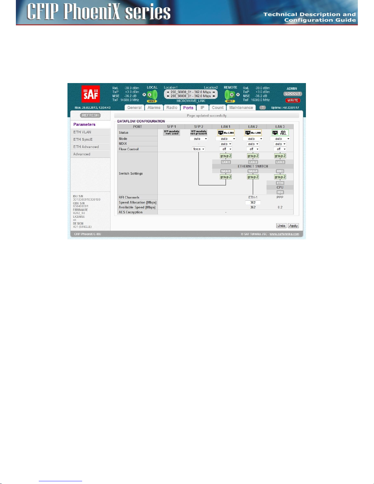
77
CFIP PhoeniX C Series TDM/IP Split Mount System Technical Description and Configuration Guide • Rev. 1.0 •
© SAF Tehnika JSC 2013
priority allocation goes from the left to the right.
– Available Speed – It indicates the available speed for appropriate channel. This value depends on
selected actual modulation scheme.
– AES Encryption – This line shows when the AES encryption block is enabled or disabled, when it
is supported with running design and firmware. This option is not available for design SINGLE.
Figure 56: Port setting in SINGLE design
Basic port settings – Design MULTI
Port settings for design MULTI offer an option to select up to four independent over air traffic
channels (Figure 57). The internal ETH switch is divided into three separate groups. Group No.1 is
usually reserved for management purposes (out of band type of management), group No.2 is
designated for the first traffic channel (the lowest priority), group No.3 is designated for the second
traffic channel (higher priority).
Other two traffic channels are connected directly to SFP PHYs, so no ETH switch is the part of such LAN
interconnection. Traffic channel ETH 4 has the highest priority inside the packet processor structure.
Page 78
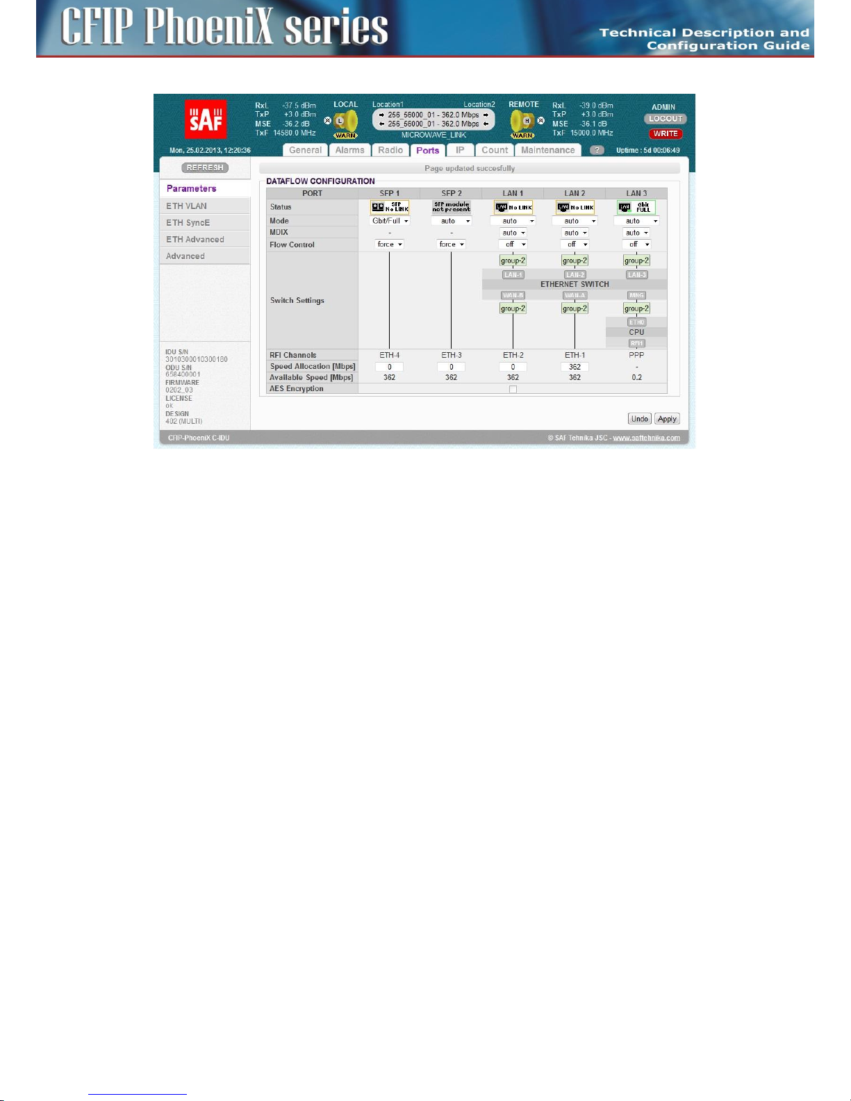
78
CFIP PhoeniX C Series TDM/IP Split Mount System Technical Description and Configuration Guide • Rev. 1.0 •
© SAF Tehnika JSC 2013
Figure 57: Ports setting in MULTI design
The Speed Allocation set-up is different in comparison with the design SINGLE. The overall allocated
traffic capacity (the sum of all ports capacity) should be in the range of available speed for actual
modulation scheme. When the adaptive modulation mode (ACM) is enabled, then the user has to
consider, what lower priority channels do not need the free capacity allocation in the case of switch to
lower level modulation scheme.
Basic port settings – Design PROTECTED
Port settings for design PROTECTED are similar to design MULTI function, but only three independent
over air traffic channels are available (Figure 58). Port SFP 1 is reserved for protection function
(interconnection with neighbour IDU).
There also exists a difference between master and slave units. All standard traffic ports (LAN 1, LAN 2,
SFP 2) are automatically disabled (DOWN) at slave unit (Figure 59). This prevents from the multipath
Ethernet loops. The same ports are also disabled when protection mode is configured into “off” mode.
Page 79
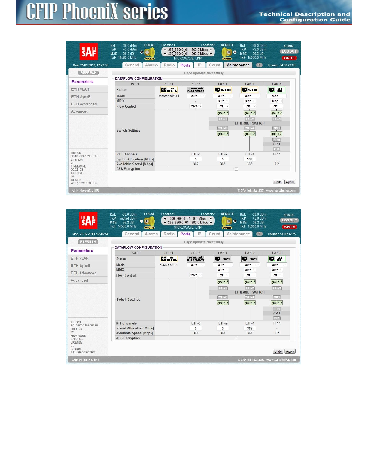
79
CFIP PhoeniX C Series TDM/IP Split Mount System Technical Description and Configuration Guide • Rev. 1.0 •
© SAF Tehnika JSC 2013
Figure 58: Ports setting in PROTECTED Master mode
Figure 59: Ports setting in PROTECTED Slave mode
Basic port settings – Design AGGREGATE
Port settings for design AGGREGATE are different for master and slave units. Traffic port SFP 1 and
channel ETH-1 at master unit are reserved for the aggregation function, next two channels ETH -2,3
can be used for next independent traffic streams (Figure 60).
Page 80
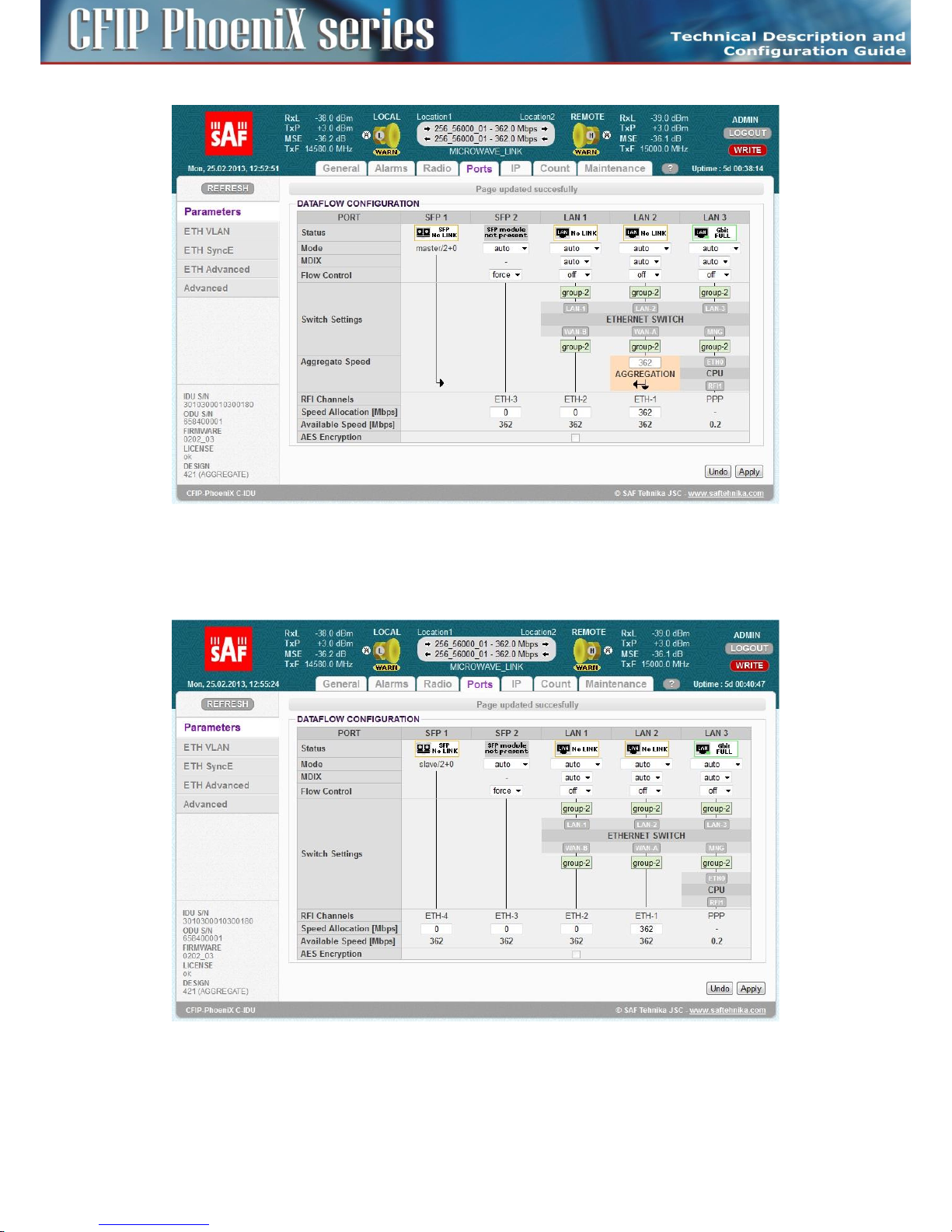
80
CFIP PhoeniX C Series TDM/IP Split Mount System Technical Description and Configuration Guide • Rev. 1.0 •
© SAF Tehnika JSC 2013
Figure 60: Ports setting in AGGREGATE Master mode
The channel ETH-4 at slave unit is reserved for the slave aggregation stream (correct speed must be
set), rest of ETH channels (ETH 1-3) is available for next independent data sources.
Figure 61: Ports setting in AGGREGATE Slave mode
Page 81

81
CFIP PhoeniX C Series TDM/IP Split Mount System Technical Description and Configuration Guide • Rev. 1.0 •
© SAF Tehnika JSC 2013
ETH VLAN settings
VLAN configuration is basically used for the separation of management traffic from other customer
data traffics. It can be useful to configure ETH VLANs also for customer traffic and filter ingress data
traffic by means of this settings in some specific applications.
The VLAN configuration is available from GUI page „Ports / ETH VLAN” (Figure 62).
Figure 62: ETH VLAN configuration page
The description of particular setting and display boxes – VLAN MODE
– Port mode – it is possible to set-up separately the required VLAN mode for each ETH switch port.
It is recommended to leave all ports in basic mode and edit VTU records first. The user has to be
sure with correct VLAN configuration and has to set also his network into the similar VLAN
support. VLAN Port modes are described bellow:
- basic – Transparent mode where VLAN settings in VTU table are ignored. Frames are
transmitted unchanged but they exit only those ports which are inside the same group.
- access – Port is a member of just one untagged VLAN defined with Default VLAN for the
port. Only such ingressed untagged packets are accepted, whose VLAN number (VID), which
is assigned from port's Default VLAN, exist in VTU table. Frames are transmitted untagged
and they are allowed to exit only those ports that are members of the frame's VLAN and are
inside the same group.
- trunk – Port can be a member of more tagged VLANs (VID extracted from VLAN tag) and
one untagged VLAN defined with Default VLAN for such port. Only such frames are
accepted, whose VLAN number (assigned from VLAN tag or port's Default VLAN) exists in
VTU table and Ingress port is member of VLAN. Frames are transmitted untagged or tagged
according to the specification in VTU record for each port/VLAN and they are allowed to
exit only those ports that are members of the frame's VLAN and are inside the same group.
- hybrid – When frame's VLAN number exists in VTU table the rules for trunk port are used,
when the number does not exist then the basic rules are applied.
– Port Group – This parameter defines a separate MAC address table domains inside the internal
switch and defines also the group of ports which can communicate to each other. Only the ports
Page 82

82
CFIP PhoeniX C Series TDM/IP Split Mount System Technical Description and Configuration Guide • Rev. 1.0 •
© SAF Tehnika JSC 2013
from the same group can communicate with one another. The other ports are completely
isolated. It is possible that isolated networks (different groups) can use the same MAC addresses
without any collision in the internal ETH switch ATU table.
– Default VLAN – This parameter is configured automatically with a new record into the VTU table.
Default VLAN is updated for the port which is marked as untagged in the VTU record. VLAN No.1
can not be added into VTU table and it is just fictive VLAN for internal purposes. The port cannot
be configured into access mode when Default VLAN of this port is 1. When Default VLAN value
for the trunk port is 1, then the port accepts just tagged frames.
The description of particular setting and display boxes – VTU SETTING
– ACTION – It adds or removes VTU records. VTU record can not be removed when contains
untagged port which is configured into access mode. Just simple VLAN NO. specification is
required for VTU record erase.
– VLAN NO. – The VLAN number of edited VLAN (added or deleted). Every VLAN can be defined
for only one Port Group, multiple records of the same VLAN for more groups is not allowed.
– GROUP – It defines the port Group for which is VLAN edited.
– QOS PRI – When VTU override mode is selected then the QOS priority value of original frame is
overrided. This configuration has influence only on the internal frame processing by means of
queue controller (QPRI defined by OQPRI instead of IQPRI bits), but frames are egressed still with
the initial priority assignment (FPRI is without any change).
– LAN 1-WAN B – It defines VLAN mode for each port in configured VLAN.
- Deny – Port is not a member of edited VLAN. Ports which are defined in different Groups
should be set into this mode.
- Untag – Port is a member of edited VLAN as untagged.
- Tag – Port is a member of edited VLAN as tagged.
The description of particular setting and display boxes – VTU LISTING
List of VTU records (defined VLANs) in the ETH switch. The abbreviations in this list correspond to the
first letter of the port mode definition in VTU records.
ETH SyncE
Synchronous Ethernet mode is supported in designs SINGLE, MULTI and AGGREGATE. This mode
ensures transmission of timing reference derived from a selected LAN port at the “reference” side of
the link to the remote „synchronized” side of the same link. This configuration is available on GUI page
„Ports / ETH SyncE” (Figure 63).
Page 83

83
CFIP PhoeniX C Series TDM/IP Split Mount System Technical Description and Configuration Guide • Rev. 1.0 •
© SAF Tehnika JSC 2013
Figure 63: ETH SyncE GUI page
The description of particular setting and display boxes
– SyncE Reference – This parameter defines the port which is selected for clock synchronization at
configured IDU. Available modes are:
- lan1-3 – Clock reference is a specific PHY port LAN 1-3.
- sfp1-2 – Clock reference is a specific SFP port SFP 1-2.
- rf – Clock reference is a receiver RF timing (locking to remote IDU).
– Clock Recovery Status – It displays PLL lock status (locked / unlocked) and source reference signal
status (source ok, source error, source not set).
– Reference Clock – It displays what internal clock reference is used for system timing. Local XTAL is
displayed when no SyncE reference is selected or PLL is not locked. Recovered CLK is a status
when system CLKs are locked to external unit.
– Port Synchronization – It is possible to select which ports will be synchronized to SyncE reference
in these boxes. Radio part (rf) is synchronized automatically when SyncE Reference is configured
to LAN 1-3 / SFP 1-2 sources.
ETH Advanced settings
ETH advanced GUI page (Figure 64) is dedicated to additional ETH configurations which extend the
basic functions of the internal ETH switch (Jumbo Frames, extended QOS, ..).
Page 84
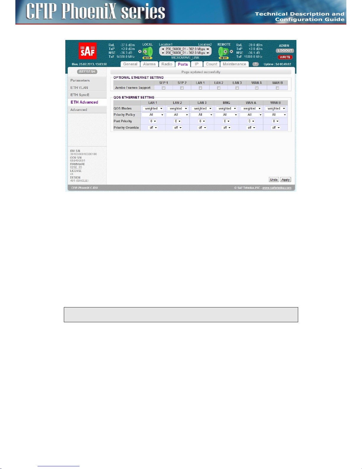
84
CFIP PhoeniX C Series TDM/IP Split Mount System Technical Description and Configuration Guide • Rev. 1.0 •
© SAF Tehnika JSC 2013
Figure 64: Advanced ETH settings
The description of particular setting and display boxes – OPTIONAL ETH
– Jumbo Frames Support – these boxes make it possible to select what ports will support Jumbo
Frames (length up to 10 kB). There exist different Jumbo frames mode settings for the ETH switch
ports (LAN1 -3, WAN A-B) and the SFP ports. Because SFP ports are not connected into ETH
switch directly and different designs use specific SFP modes, the user himself has to decide about
the correct Jumbo frame configuration.
- In SINGLE design – Just Jumbo Frame setting for LAN and WAN port is important. The
setting of SFP boxes does not affect the proper ETH function.
- In MULTI design – All selection boxes have an influence on Jumbo Frames function.
- In PROTECTED design – Jumbo frames setting for port SFP 1 (protection port) does not
affect correct protection function.
NOTE: Jumbo Frames Support reserves more space in ETH switch FIFO and especially in packet
processor FIFO. Therefore number of buffered packets is limited in this mode.
The description of particular setting and display boxes – QOS ETH
This section makes it possible to configure extended QOS modes which are important for a specific
traffic prioritization. The system uses four priority queues for each port where frames, with an
assigned initial frame priority, an initial queue priority and an override queue priority, are mapped
onto four output queues according to QPRI settings. A final frame queue priority is derived from the
assigned initial queue or the override queue priority and it is used for deciding what queue will be used
for frame buffering. The queue with a higher number is egressed with higher priority than the queues
with lower numbers. The assigned initial frame priority is then used for replacing of frame's PRI bits in
802.3ac VLAN tag section, when the frame is egress tagged.
Page 85

85
CFIP PhoeniX C Series TDM/IP Split Mount System Technical Description and Configuration Guide • Rev. 1.0 •
© SAF Tehnika JSC 2013
Priority abbreviations
– FPRI initial frame priority 0 up to 7 (bits [2:0])
– QPRI queue priority 0 up to 3 (bits [1:0])
– IQPRI initial queue priority 0 up to 3 (bits [1:0])
– OQPRI queue override priority 0 up to 3 (bits [2:1] from QOS PRI value)
– PRI_T PRI bits from 802.ac VLAN tag
– PRI_IP hex value of IP v4/6 frame's TOS/DiffServ/TC bits [7:2]
Port default priority
– FPRI_D = port default frame priority, defined with Port Priority value
– QPRI_D = port default queue priority, defined with next mapping table
- QPRI_D = 0 when FPRI_D=0/1
- QPRI_D = 1 when FPRI_D=2/3
- QPRI_D = 2 when FPRI_D=4/5
- QPRI_D = 3 when FPRI_D=6/7
IEEE Tag priority
– FPRI_T = IEEE Tag frame priority, defined with value of PRI bits from VLAN tag
– QPRI_T = IEEE Tag queue priority, defined with next mapping table
- QPRI_T = 0 when FPRI_T=0/1
- QPRI_T = 1 when FPRI_T=2/3
- QPRI_T = 2 when FPRI_T=4/5
- QPRI_T = 3 when FPRI_T=6/7
IP v4/6 priority
– FPRI_IP = IPv4/6 frame priority, defined with following figure
- FPRI_IP = QPRI_IP*2 + FPRI_D[0]
or defined in another way
- FPRI_IP[2:1] =QPRI_IP[1:0]
- FPRI_IP[0] = FPRI_D[0]
– QPRI_IP = IPv4/6 queue priority, defined with next mapping table (hex values)
- QPRI_IP = 0 when PRI_IP=00/04/08/0c/10/14/18/1c/20/24/28/2c/30/34/38/3c
- QPRI_IP = 1 when PRI_IP=40/44/48/4c/50/54/58/5c/60/64/68/6c/70/74/78/7c
- QPRI_IP = 2 when PRI_IP=80/84/88/8c/90/94/98/9c/a0/a4/a8/ac/b0/b4/b8/bc
- QPRI_IP = 3 when PRI_IP=c0/c4/c8/cc/d0/d4/d8/dc/e0/e4/e8/ec/f0/f4/f8/fc
There is a detailed explanation of all possible QOS modes in the following description:
– QOS Modes – This drop-down menu defines egress queue policy function. The function is
independent of any other QOS configurations. Each egress frame is assigned with such queue
whose number is identical to frame's QPRI identifier.
- weighted – In the weighted scheme an 8, 4, 2, 1 round robin weighting is applied to the four
priorities (8 frames from Q3, 4 frames from Q2, 2 frames from Q1 and 1 frame from Q0).
This approach prevents the lower priority frames from being starved out with only a slight
delay to the higher priority frames.
- strict 3xxx – Strict priority for queue 3 and weighted round robin for queues 2,1 and 0.
Queues 2,1,0 are served only when Q3 is empty.
- strict 32xx – Strict priority for queues 3,2 and weighted round robin for queues 1 and 0.
Queues 1,0 are served only when Q3 and Q2 are empty.
- strict 3210 – Strict priority for all queues. Lower priority queues are served only when higher
Page 86

86
CFIP PhoeniX C Series TDM/IP Split Mount System Technical Description and Configuration Guide • Rev. 1.0 •
© SAF Tehnika JSC 2013
priority queues are empty.
NOTE: QOS Mode configures egress policy (output from switch) for each port, whereas other QOS
setting modes configure ingress port policies (input to switch). Therefore priority assignment is
done at the input to the switch and function of queue controller is defined at the output from the
switch.
– Priority policy – This drop-down menu defines the initial ingress queue policy. It defines the initial
rules for what output queue will be assigned to every ingress frame.
- All – Next rules are used for priority assignment (from the top to the bottom order).
tagged IPv4/6 frames
IQPRI = QPRI_T
FPRI = FPRI_T
tagged non IPv4/6 frames
IQPRI = QPRI_T
FPRI = FPRI_T
untagged IPv4/6 frames
IQPRI = QPRI_IP
FPRI = FPRI_IP
untagged non IPv4/6 frames
IQPRI = QPRI_D
FPRI = FPRI_D
- Port only – Next rule is used for priority assignment.
all frame types
QPRI = QPRI_D
FPRI = FPRI_D
- Tagged only – Next rules are used for priority assignment (from the top to the bottom
order).
tagged frames
IQPRI = QPRI_T
FPRI = FPRI_T
untagged frames
QPRI = QPRI_D
FPRI = FPRI_D
- IPv4/6 only – Next rules are used for priority assignment (from the top to the bottom
order).
IPv4/6frames
IQPRI = QPRI_IP
FPRI = FPRI_IP
non IPv4/6 frames
IQPRI = QPRI_D
FPRI = FPRI_D
– Port Priority – The configuration of default port priority. Value 0 up to 7 can be entered (0 is
default value) and it is then used for definition of FPRI_D and QPRI_D parameters according to
the above described figures. The next possible function of this variable is a definition and/or
replacement of QOS priority information based on FPRI_D for frames which are egressed with
Page 87

87
CFIP PhoeniX C Series TDM/IP Split Mount System Technical Description and Configuration Guide • Rev. 1.0 •
© SAF Tehnika JSC 2013
VLAN tag. Such updated frame can input into the switch with QOS priority which is different from
priority of the same frame at the output from switch.
– Priority Override – It offers the possibility to replace an initial queue priority with a new priority.
The new priority is assigned to each frame whose VLAN ID is defined in the VTU table with
properly configured QOS PRI value.
- off – QOS override is disabled.
- vtu – Queue priority override information (OQPRI) is derived from bits [2:1] of QOS PRI
parameter defined in chapter The description of particular setting and display boxes – VTU
SETTING on page 82. When this parameter is set to off state, override process is not active
for appropriate VTU record, even though Priority override is enabled on the port.
Advanced Port settings
Advanced Port settings GUI page offers a configuration of extended modes which are associated with
packet processing. The only available setting on this GUI page in this firmware is a definition of the
AES encryption (Figure 65).
Figure 65: Advanced Port setting GUI Page
The description of particular setting and display boxes
– AES function – This box enables or disables AES encryption function. The function is a subject to
a valid license option and an entered valid AES key. When the checkbox is selected then whole
traffic stream from packet processor is encrypted with entered AES key. The opposite IDU must
be defined in the same way and with identical AES key. Out of band management channel is not
encrypted in this mode, therefore remote access to remote IDU is possible in any way.
– AES key status – This information line shows status of actual AES key and also last four digits of
the entered valid key.
– AES key input – AES key must be entered for initial key definition or change prior to initiation of
AES function.
ATTENTION: AES option is not available for design SINGLE.
Page 88

88
CFIP PhoeniX C Series TDM/IP Split Mount System Technical Description and Configuration Guide • Rev. 1.0 •
© SAF Tehnika JSC 2013
IP configurations
In respect of management access type it is possible to use either the local connection via LAN 3 port
which is connected to the Ethernet switch and it is interconnected by default with the port ETH 0 on
management CPU or via USB B port which is connected directly to the management CPU over port
USB 0. Other IP ports on the CPU are primarily used for management interconnection with a remote
IDU (RFI 1) or with a protection/aggregate unit (HSI1).
Basic IP addresses assignment
Every device in the local network has its own and unique primary IP address. Thanks to this IP address
it is possible to access each equipment in your network. While setting-up the IP address, pay attention
to the configuration which needs to follow general IP addressing rules (IP address, IP netmask, IP
gateway). Customer has to ensures that correct IP addresses are assigned and configured for all units
in the microwave network. It is recommended to prepare short block scheme of all IDUs
interconnection in such microwave network and select appropriate model for IP addresses setting
according to the required type of IP management access (in-band /out-of-band).
The basic IP setting should be done during installation process described in chapter IP setting on page
54. We recommend to check and update again all parameters at all IP pages. These parameters must
be entered for each IDU according to the management block scheme.
The description of particular setting and display boxes
– Primary IP / Mask – IP address assigned to port ETH0 (local address) with appropriate net-mask
specification. Net-mask value is entered in form of decimal number which corresponds to
number of ones in binary subnet mask presentation. Such net-mask for subnet mask
255.255.255.0 is presented as decimal number 24. Local network has its own and unique primary
IP address.
– Default Gateway IP – Default Gateway IP address is used with CPU when connection outside IP
range defined in system routing table is required. Such IP address must be a part of above
mentioned routing table. Routing table can be checked on page „IP / Route/NAT”.
– Remote Unit IP – Such address specifies a remote unit IP connected over RF link. Such address is
necessary for automatic message exchange between these IDUs and also for correct out-of-band
management functionality. Subnet mask is not required for this IP specification, because ppp
protocol is used.
– Protection/Aggregate Unit IP – Such address specifies the neighbour unit IP (protection or
aggregate) connected over FO. Such address is necessary for automatic message exchange
between these IDUs and also for correct out-of-band management functionality. Subnet mask is
not required for this IP specification. This setting is necessary for Protected and Aggregate
designs only.
Page 89

89
CFIP PhoeniX C Series TDM/IP Split Mount System Technical Description and Configuration Guide • Rev. 1.0 •
© SAF Tehnika JSC 2013
Figure 66: Basic IP setting
All IP settings are applied in two steps.
Temporary configuration IP file is changed with pressing APPLY button, but setting changes are not
immediately applied to the running system. After the button press an intermediate confirmation
window appears (Figure 35). There are two possible ways how to proceed.
When Continue button is pressed, then the user prefers to continue with IP changes (static routes,
NAT, advanced IP setting, SNMP, ..). There is a reason for such selection, because it is recommended to
apply all IP changes in one step. Any change in the temporary configuration IP file is indicated by
means of warning message in the status line at each IP page.
Complete IP changes will be immediately applied to the running system with pressing Write And Apply
button in intermediate window.
NOTE: P configuration changes did not cause data drop in the user traffic.
Static Route and NAT settings
For a specific configuration of management access it is sometimes necessary to add/change/delete
static routes or NAT records. This is especially required for Out of band type of management access. To
edit these parameters noticed above GUI page „IP / Route/NAT” must be selected (Figure 67).
Page 90
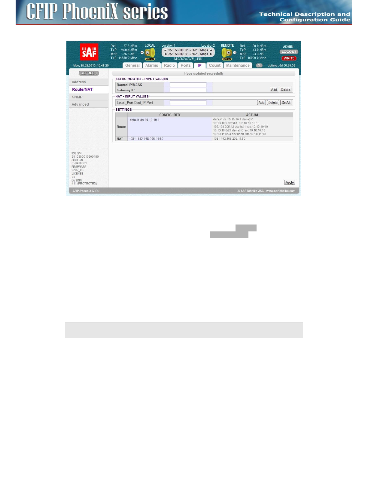
90
CFIP PhoeniX C Series TDM/IP Split Mount System Technical Description and Configuration Guide • Rev. 1.0 •
© SAF Tehnika JSC 2013
Figure 67: Static route and NAT setting
Each static route and/or NAT record must be entered separately. The same confirmation window as for
IP address configuration appears after each record input erase. The Continue button should be
pressed for proceeding with any other IP settings. The button Write And Apply should be selected for
applying all IP settings to running system after last record input (when other IP configuration is not
required).
The description of particular setting and display boxes – Static Routes
– Routed IP / MASK – The IP address from routed network and the appropriate network mask
must be entered. Routed network range is calculated from entered values.
– Gateway IP – The correct IP address gateway for above network must be entered.
The ADD button is used for entering new route into the routing table, the DELETE button for deleting
record from the routing table.
NOTE: It is not required to fill in the Gateway IP address when record from the routing table should
be deleted.
The description of particular setting and display boxes – NAT changes
– LocalPort DestIP:Port – The NAT record must be entered in the form of following command:
- local_port destination_ip: port
local_port – The number of a port on local IP which is used for address translation, it
must be followed with space character.
destination_ip – IP address of destination/remote unit.
port – Port number of service at destination/remote IP.
Example: 1080 192.168.4.101:80
Page 91

91
CFIP PhoeniX C Series TDM/IP Split Mount System Technical Description and Configuration Guide • Rev. 1.0 •
© SAF Tehnika JSC 2013
The ADD button is used for entering a new NAT record into the NAT table, alternatively the
DELETE button for deleting record from the NAT table. Optionally the DELALL button can be
used for deleting all NAT records in one step.
Routing Table and NAT table checking
It is possible to compare Routing and NAT tables of running system (ACTUAL) with records in
temporary configuration file (CONFIGURED) in the section SETTING.
There are displayed only added routes and NATs compared to default setting in the column
CONFIGURED. This section should contain default gateway record in minimum, because this one is a
member of the same definition file as other static routes.
There are additionally displayed static routes generated internally with the system core in the column
ACTUAL. There is a small difference in form of records in CONFIGURED and ACTUAL columns.
Any difference between actual and configured IP setting is indicated in the status line on all IP pages
with an alert message „IP settings are not currently applied – press APPLY button”.
The user can compare both sections also visually, when detailed analysis is required.
SNMP settings
SNMP management can be set on GUI page „IP / SNMP” (Figure 68). Just SNMP traps are supported in
current firmware release.
The description of particular setting and display boxes
– Trap Port – The parameter specifies which port will be used for SNMP trap type messages. The
same configuration must be set also at SNMP agent station.
– Trap Address 1-3 – Up to three IP addresses can be configured as destination for SNMP trap
distribution. Trap message events are configured in the same way as the alarm setting.
Page 92

92
CFIP PhoeniX C Series TDM/IP Split Mount System Technical Description and Configuration Guide • Rev. 1.0 •
© SAF Tehnika JSC 2013
Figure 68: SNMP setting
Advanced IP settings
The advanced IP section makes it possible to change extended IP configuration which usually remains
in default state. This can be sometimes necessary for support of specific management modes.
Advanced management setting is accessible on GUI page „IP / Advanced” (Figure 69).
ADVANCED ADDRESS SETTING
– USB IP/MASK – It specifies IP address for USB management port. When default IP address for
this port is in collision with other network configuration, it can be changed with this parameter.
– Secondary IP/MASK – It specifies secondary IP address for ETH 0 management port. When
default IP secondary address is in collision with other network configuration, it can be changed
with this parameter.
– RFI1 port IP (PPP) – It specifies internal IP address for RFI 1 port (which connect remote unit).
Default RFI1 IP address uses the same value as ETH 0 port (unnumbered mode). It can be helpful
to set numbered ppp mode for a specific network configuration.
– HSI1 port IP (PPP) – It specifies internal IP address for HSI 1 port (which connect neighbour unit).
Default HSI 1 IP address uses the same value as ETH 0 port (unnumbered mode). It can be helpful
to set numbered ppp mode for a specific network configuration.
FILE TRANSFER
– FTP/USB Server – When „usb” is written into this box the USB - A port is used as
destination/source interface for backup and/or restore IDU configuration. When box is filled in
with ftp://IP/directory_structure/ an external FTP server is used as destination/source address
for backup and/or restore IDU configuration.
REMOTE TIME SERVER
– Server Type – Two types of time server can be specified for a time synchronization: ntp or rdate.
Page 93
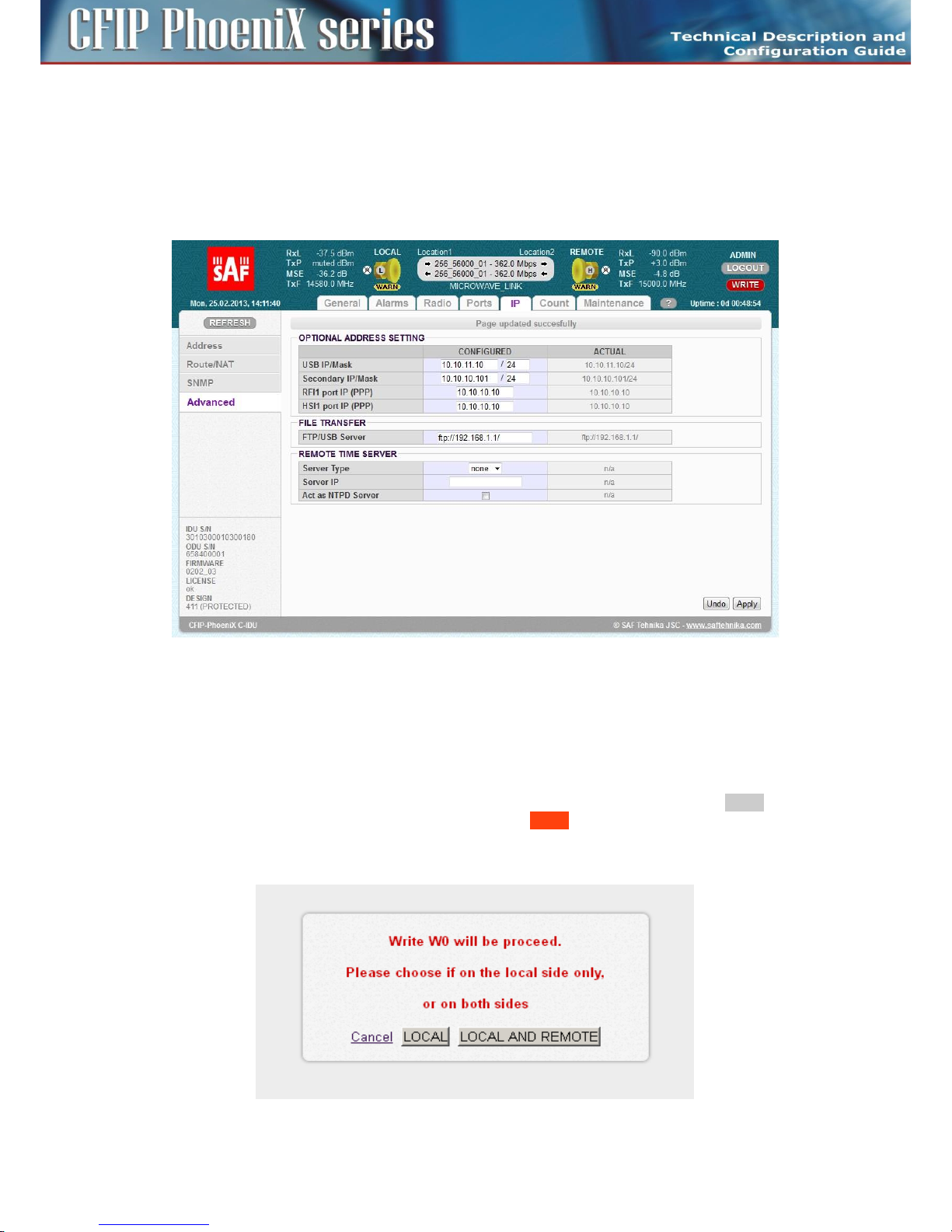
93
CFIP PhoeniX C Series TDM/IP Split Mount System Technical Description and Configuration Guide • Rev. 1.0 •
© SAF Tehnika JSC 2013
The most useful setting is ntp mode. When “none” is selected, no time synchronization is
required.
– Server IP – It specifies a remote time server IP when ntp or rdate mode are selected in the box
Server Type.
– Act as NTPD Server – When this checkbox and ntp type of time server are selected then the
CONFIGURED unit operates as NTPD reference server. Time at remote units can be synchronized
with this CONFIGURED unit.
Figure 69: Advanced IP setting
Maintenance and advanced system configuration
Saving the configuration
In order that the configured and modified link parameters are valid even after the equipment is power
cycled (or after device restart), the new configuration must be saved first. The button WRITE is
available on each GUI page. Red background of the button WRITE indicates that the actually running
configuration is not saved in the start-up memory yet. An intermediate window appears after the
write button press (Figure 70). User can select if a configuration for local unit or both local and remote
units is stored.
Page 94

94
CFIP PhoeniX C Series TDM/IP Split Mount System Technical Description and Configuration Guide • Rev. 1.0 •
© SAF Tehnika JSC 2013
Figure 70: Write confirmation
When the configuration is properly saved, it is possible to write actual configuration also into optional
memories (W1-W3). This operation saves actual settings as alternative configuration for subsequent
quick restoration of such configuration scheme with relevant RUN W0 – RUN W3 button click
(Figure 71).
Button RETURN TO PREVIOUS PAGE in the right bottom corner of GUI page helps to quick return to the
previous active page.
ATTENTION: Make sure that all modes work properly and remote access to IDU is still possible
before start-up memory saving. The automatic restore function can not return to the status before
start-up memory saving then.
Figure 71: Write and Run commands
Configuration backup and export
It is recommended to make a backup of complete IDU configuration for an eventual system fault. In
order to guarantee quick system repair or units replacement this backup configuration should be
stored on reliable medium.
The access to backup process is available from GUI page „Maintenance / Files” (Figure 72).
Backup procedure
A description of recommended steps for the backup configuration follows:
– Login over web browser with ADMIN rights.
– Save currently running configuration with WRITE button, which is available on each GUI page.
Then the start-up memory will contain the actual configuration.
– Select Save Config checkbox in section FILES and press GENERATE.
– Press right mouse button on fwconf_xxx_xxx.afw file, and select destination for this file and save
it.
Page 95
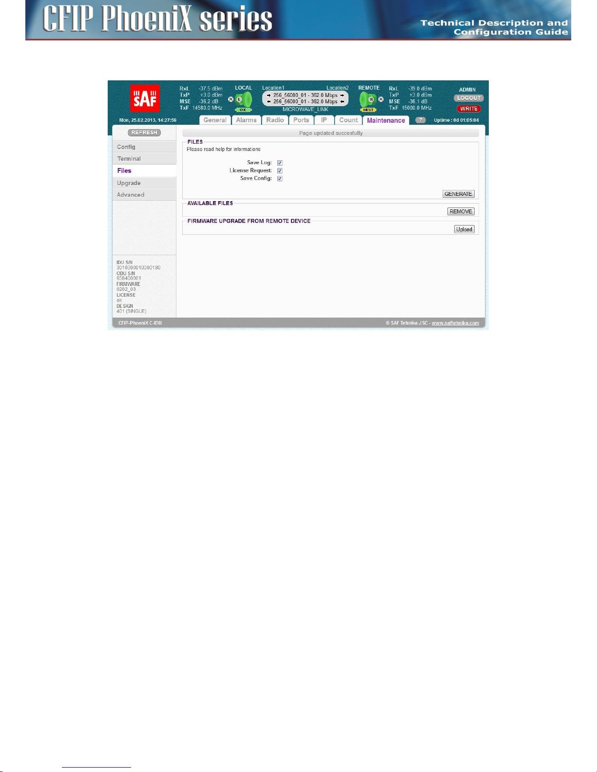
95
CFIP PhoeniX C Series TDM/IP Split Mount System Technical Description and Configuration Guide • Rev. 1.0 •
© SAF Tehnika JSC 2013
– The configuration is now saved in your PC and alternatively in USB memory stick.
Figure 72: Configuration, Logs and License Request backup
A detailed description of other settings available on this GUI page follows:
FILES
It is possible to select what files are going to be generated for subsequent backup in the section FILES.
– Save Log – Compressed log files in tar gzip form usually used for troubleshooting purposes.
– License Request – A copy of License File in encoded form. This can be used for subsequent
generation of new license by your representative. This file prevents any mistakes in defining
what active license is loaded in the IDU.
– Save Config – This encoded file contains the complete backup configuration of IDU. When
this file is uploaded into another IDU, then all original system settings and configurations are
replaced with this backup configuration.
The required files will be generated for next processing after pressing of the button GENERATE. When
a USB memory stick is attached into USB A port and USB is defined as a destination for the file transfer
(check chapter Advanced IP settings on page 92), then the same files will be saved also to USB
memory.
AVAILABLE FILES
Generated files are visible in this section. The save dialogue window will appear after pressing the
right mouse button, then the individual files can be saved to selected destination. Name of each file is
the combination of a file identifier, IDU_SN and actual time mark.
FIRMWARE UPGRADE FROM REMOTE DEVICE
This selection make it possible to upload any encoded *.afw file into specific directory in local IDU.
This file can be subsequently downloaded and processed by remote unit by means of CLI command
entered on remote unit. This is useful in case when access to remote IDU is available only from
command line of local IDU over TELNET / SSH. This can be in some cases the only way how to change
license or upgrade firmware on remote unit. The alternative and more preferred way is to use out-ofband connection to remote unit by means of NAT function (see chapter Static Route and NAT settings
Page 96

96
CFIP PhoeniX C Series TDM/IP Split Mount System Technical Description and Configuration Guide • Rev. 1.0 •
© SAF Tehnika JSC 2013
on page 79)
Firmware and License upgrade
Firmware and license upgrade is available in ADMIN mode only.
We recommend to verify the loaded version of firmware in the IDUs before upgrading or updating the
license of microwave link. It is possible that the IDU with older FW does not recognize the new
designs, options or functions contained in new license key and will not run properly.
Both Firmware and License upgrade are available from GUI page „Maintenance / Upgrade” and use
the identical update process. An intermediate window will appear after selection of this page.
Figure 73: Firmware/License upgrade
License Upgrade
Proper license file must be selected and confirmed by OK button. Upgrade process is then monitored
at processing window. New license is active after one of next events:
– New license is checked by selection GUI page General/License.
– New modulation is selected.
– When periodical license update loop is over (once per 6 hours).
Firmware Upgrade
IDU firmware is divided into four sections in dependence on their functions. For every firmware
release it is not necessary to update all the parts, but only these ones which are different comparing
to the newest version. There is basic firmware parts description in the following text.
– hwbase.afw – software for internal HW parts
– oskernel.afw – operating system
– dev.afw – drivers for OS
– fwbase.afw – application software (WEB, SNMP, commands , etc.)
Assistance packages are also contained in every firmware release
– checkversions.afw – This package compares the firmware version in IDU with the newest version
and prints the info what parts are necessary to upload.
– fw_all.afw – First of all this package compares the current version of firmware in IDU with the
newest version and then automatically upload the different parts.
The description of recommended steps for firmware update
– Login over web browser with ADMIN rights.
– Save currently running configuration by WRITE button, which is available on each GUI page. Then
the start-up memory will contain the actual configuration.
– Compare currently running versions of each firmware parts (os_kernel, os_dev, hw_base and
fw_base) with the newest version by one of two below given steps.
- manually compare data shown in a folder „General / Info” with the new version of
description file version.txt
- Open the folder „Maintenance / Upgrade”, select package checkversions.afw and use the
Page 97
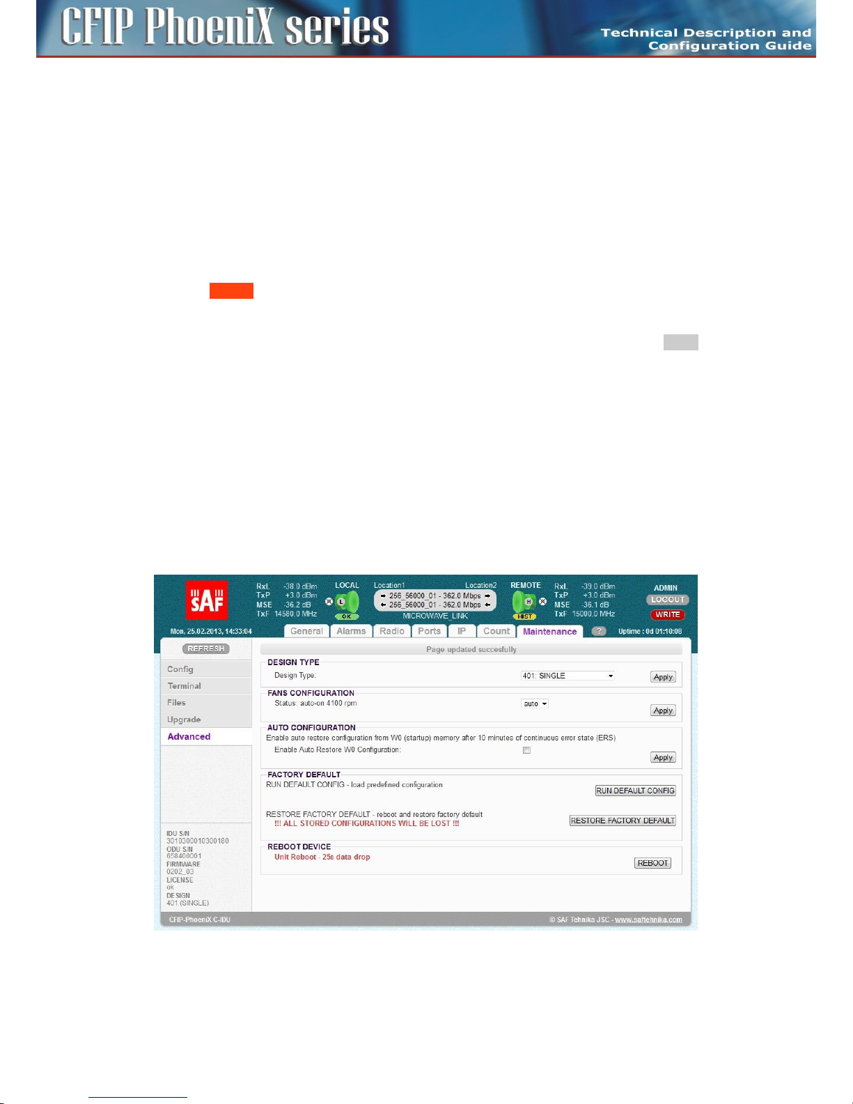
97
CFIP PhoeniX C Series TDM/IP Split Mount System Technical Description and Configuration Guide • Rev. 1.0 •
© SAF Tehnika JSC 2013
print-out for information, what parts should be upgraded.
– Next choose one of the following steps.
- Select the file fw_all.afw from the provided SW package. The whole file will be uploaded
into the device, system compares the different versions and writes the different parts of the
firmware into flash memory.
!! This procedure isn't suitable for slow access to IDU management !!
- Step by step select the files hwbase.afw, oskernel.afw, dev.afw and fwbase.afw in this order
(if there is not necessary to upload any part, please continue with another file) and wait for
the process completion.
– After the last file upload.
- Restart the device from the folder „Maintenance / Advanced” with pressing button
REBOOT.
!! During restart there is a data drop for about 20 sec !!
- Login again with ADMIN rights and update start-up memory configuration with the newest
functional setting available in the newest firmware. Save the new configuration with WRITE
button, which is available on each page.
- Make a new IDU initialization from the start-up memory. Select Run_W0 on the page
„Maintenance / Config”.
!! During initialization there is data drop for about 5 sec !!
– New firmware is now properly installed in the IDU.
Advanced system configuration
Advanced system configuration, which could be important for correct system function, is accessible on
GUI page „Maintenance / Advanced” (Figure 74).
Every setting must be applied separately by appropriate APPLY button. There is a description of
particular setting and display boxes in the next text.
Figure 74: GUI page „Maintenance / Advanced
– DESIGN TYPE – According to the license file content a user can select specific Design Type which
changes complete system function. Design change involves reboot of FPGA and correct hwbase
software loading. The setting must be applied by appropriate APPLY button. Possible selections
Page 98

98
CFIP PhoeniX C Series TDM/IP Split Mount System Technical Description and Configuration Guide • Rev. 1.0 •
© SAF Tehnika JSC 2013
are:
- SINGLE – One independent traffic channel over air
- MULTI – Up to four independent traffic channels over air
- PROTECTED 1+1 – Link protection by means of two IDUs
- AGGREGATE 2+0 – Speed aggregation by means of two IDUs
– FANS CONFIGURATION – Three modes are available. Speed of fan is controlled according to IDU
temperature in “auto” mode, fan is constantly running in „on” mode and fan is turned off in “off”
mode. Auto mode is preferred option.
– AUTO CONFIGURATION – Start-up configuration is loaded after 10 minutes continuous error
state when the check box is selected. It is recommended to disable this function during link
configuration and installation.
– FACTORY DEFAULT – Two different factory settings are available.
- RUN DEFAULT CONFIG – It restores the default configuration of the most important IDU
parts but some customer specific settings remain without change (design type, IP section,
TX/RX frequencies, Tx Power, modulation type). It allows to keep remote connection with
IDU but helps to return default configuration of extended configuration modes. The
restored configuration must be then stored into start-up memory by means of write button.
- RESTORE FACTORY DEFAULT – It restores the complete factory default configuration. All
stored configuration will be lost. This selection should be used only when local
management access to IDU is ensured.
ATTENTION: It is strictly recommended to backup (flash disk, PC) actual configuration before
applying RESTORE FACTORY DEFAULT.
– REBOOT DEVICE – IDU is restarted after this selection.
ATTENTION: Device reboot causes approx. 20 seconds data drop.
Page 99

99
CFIP PhoeniX C Series TDM/IP Split Mount System Technical Description and Configuration Guide • Rev. 1.0 •
© SAF Tehnika JSC 2013
Chapter 5 – Configuration Examples
Example 1 – In-Band management separated by VLAN
In-Band management configuration with management traffic separation by means of VLAN is a
preferred scheme when just one ETH connection (management & data traffic) into microwave link is
accomplished. Communication with remote side is ensured by sharing common capacity for data and
management traffics through internal ETH switch.The management data together with the user data
are brought via the common Gigabit cable from the external Ethernet switch to IDU. The management
traffic must be marked by unique tagged VLAN and the same VLAN is then used in whole management
network for management traffic separation.
The application example is shown on the Figure 75.The configuration of the most important GUI pages
at LOCATION 1 (provider side) is shown on the figures 76 - 79.
This concrete example describes application where SINGLE design is selected on both link sides,
modulation is QAM128 in BW 30 MHz and appropriate maximal data speed is about 169 Mbps. IP
addresses of both IDUs are from the same IP subnet, because this scheme is similar to switched
Ethernet network. The slow separated management channels is also used in this configuration but
only for periodical message exchanges between both IDUs. The remote management connection is
available from port LAN 1 or alternatively from ports LAN 2, SFP 2 (WAN B) and WAN A (over air
connection) in form of tagged frames with VLAN #100. The alternative local management connection
is available through the LAN 3 port on each IDUs. This port accepts only untagged frames, the port is
member of managed VLAN #100 (access mode). The whole data traffic is transparent between both
IDUs excluding VLAN #100 which is reserved for management purposes. The CPU management port
ETH 0 is accessible only from such management VLAN. The VLAN setting corresponds with appropriate
explanation in chapter ETH VLAN settings on page 81.
In-Band management configuration with VLAN is supported by all designs (SINGLE, MULTI,
AGGREGATE, PROTECTED).
Main Advantages
– Fast management access to local and remote IDU.
– Just one Ethernet cable is required for data and management traffic connection.
Disadvantages
– Management traffic shares capacity with data traffic.
– It is required to know what is a type of customer traffic, especially VLAN configuration at
provider and customer side.
Page 100

100
CFIP PhoeniX C Series TDM/IP Split Mount System Technical Description and Configuration Guide • Rev. 1.0 •
© SAF Tehnika JSC 2013
Figure 75: Example 1 – In-Band management separated by means of VLAN
IDU1 (provider side)
IDU2 (customer side)
Maintenance | Advanced
Design
single
single
IP | Address
Local IP
10.10.10.10/24
10.10.10.9/24
Remote IP
10.10.10.9
10.10.10.10
Gateway IP
10.10.10.1
10.10.10.1
Ports | Parameters
Speed Allocation [Mbps]
ETH1 = 362
ETH1 = 362
Ports | ETH VLAN
Port Mode
hybrid = lan1/2, wanA/B
access = lan3, mng
hybrid = lan1/2, wanA/B
access = lan3, mng
Port Groups
1 = all ports
1 = all ports
VTU Setting
add 100 group1 off TTUUTT
add 100 group1 off DDUUTD
Design SINGLE must by selected as the first step in configuration process on both IDUs.
 Loading...