

SAF 50S15, 90S18 Owner's Manual
Owner’s Manual
XL-KP11695BM-en-DE Rev. A
Translation of the original owner's
manual
SAF fifth wheel kingpin 50S15 - 90S18

1.1 Dear customer,
This operating manual will help you to familiarise yourself with the SAFHOLLAND product and use it for its proper use.
The operating manual contains important instructions on how to operate
the product safely, properly and economically. Adherence to it helps
prevent hazards, faults and reduce down times and increase the reliability
and service life of the product. Read the operating manual through
carefully and follow the instructions accurately.
It must be ensured that all personnel with responsibility for performing
tasks on the vehicle are able to consult the operating manual at all times.
The operating manual must be kept in the glove compartment in the
driver's cabin of the towing vehicle at all times.
1.1 Copyright
This operating manual is classified as in accordance with the law on unfair
competition.
All rights reserved by
SAF-HOLLAND GmbH
Hauptstraße 26
D-63856 Bessenbach
This operating manual contains text and drawings that without the express
permission of the manufacturer cannot be either fully or partly
• duplicated,
• distributed or
• in any other way disclosed.
Any breach or infringement will result in liability for damages.
2
XL-KP11695BM-en-DE Rev. A · 02.2015 · Errors and changes excluded · © SAF–HOLLAND
en

Table of Contents
1 Product data.................................................................................. 4
1.1 Product description ................................................................... 4
1.2 Product identification ................................................................ 4
1.3 Type designation ....................................................................... 6
2 Ordering spare parts..................................................................... 11
3 General information..................................................................... 11
3.1 Liability ..................................................................................... 11
3.2 Warranty and general terms and conditions of business ............ 12
3.3 Environmental protection .......................................................... 12
4 Safety............................................................................................. 12
4.1 Target group ............................................................................. 12
4.2 Proper use ................................................................................ 13
4.3 Improper use ............................................................................ 13
4.4 Safety instructions and symbols used ........................................ 13
4.5 Marking used for sections of text .............................................. 14
4.6 General safety instructions ........................................................ 14
5 Installation..................................................................................... 16
5.1 General instructions for installation ........................................... 16
5.2 D Value/fifth wheel kingpin ....................................................... 17
5.3 Welding the flange ................................................................... 19
5.4 Installation of the fifth wheel kingpin ........................................ 21
5.5 Screw home the fifth wheel kingpin .......................................... 23
6 Implementation............................................................................. 23
7 Inspection...................................................................................... 24
7.1 General test instructions ........................................................... 24
7.2 Before each journey .................................................................. 25
7.3 Test schedule ............................................................................ 25
7.4 Wear check ............................................................................... 26
7.5 Lubricate ................................................................................... 28
8 Maintenance.................................................................................. 29
8.1 General maintenance instructions ............................................. 29
8.2 Torques .................................................................................... 29
Table of Contents
3
XL-KP11695BM-en-DE Rev. A · 02.2015 · Errors and changes excluded · © SAF–HOLLAND
en
1 Product data
1.1 Product description
The fifth wheel kingpin consists of:
• Pin
• Flange
• Screws
is the connecting shaft between the fifth wheel installed on the tractor
and that installed on the articulated trailer (trailer). The flange is welded to
the bolster plate. The kingpins comply with the applicable standards in
terms of their dimensions beneath the bolster plate.
1.2 Product identification
Pin
Please have the exact part number of the product ready when ordering
spare parts.
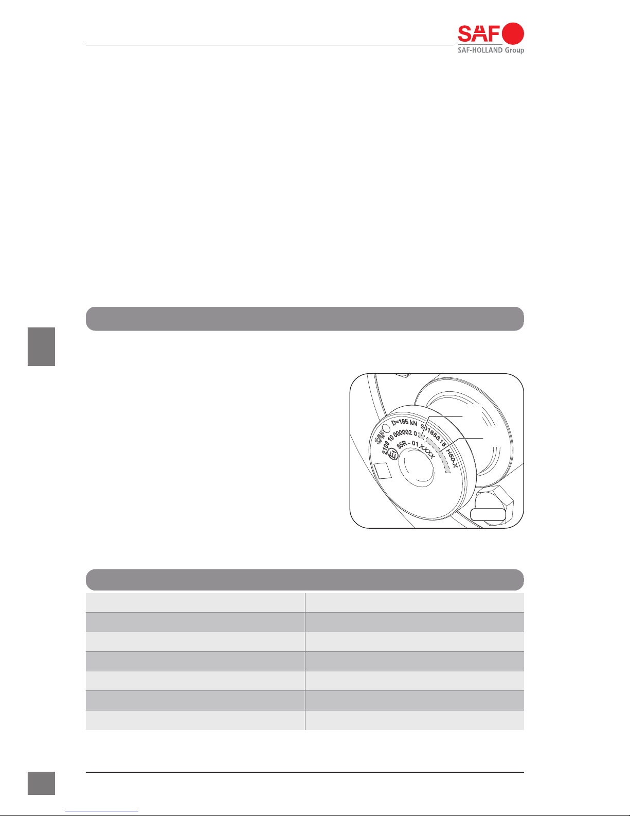
The details of the pin are engraved on
the top and bottom –Arrow–, Fig. 1. The
“D-value” is given in kilonewton .
Pin details
Technical designation Value/detail
Manufacturer/brand SAF
permitted D-value: D = 165 kN
Design: 50165S15
Class: H50–X
Part number: 2108 10 0000002 0
Revision: *1
KP-0001
*1
*2
Fig. 1 · Pin example 50S15
1 Product data
4
XL-KP11695BM-en-DE Rev. A · 02.2015 · Errors and changes excluded · © SAF–HOLLAND
en
Technical designation Value/detail
Manufacturing site and serial number: *2
Approval number: E1 55R – 01 XXXX
Data-Matrix-Code □: contains documentation and
manufacturing data, which are
centrally stored at SAF-HOLLAND
Flange
Please have the exact part number of the product ready when ordering
spare parts.
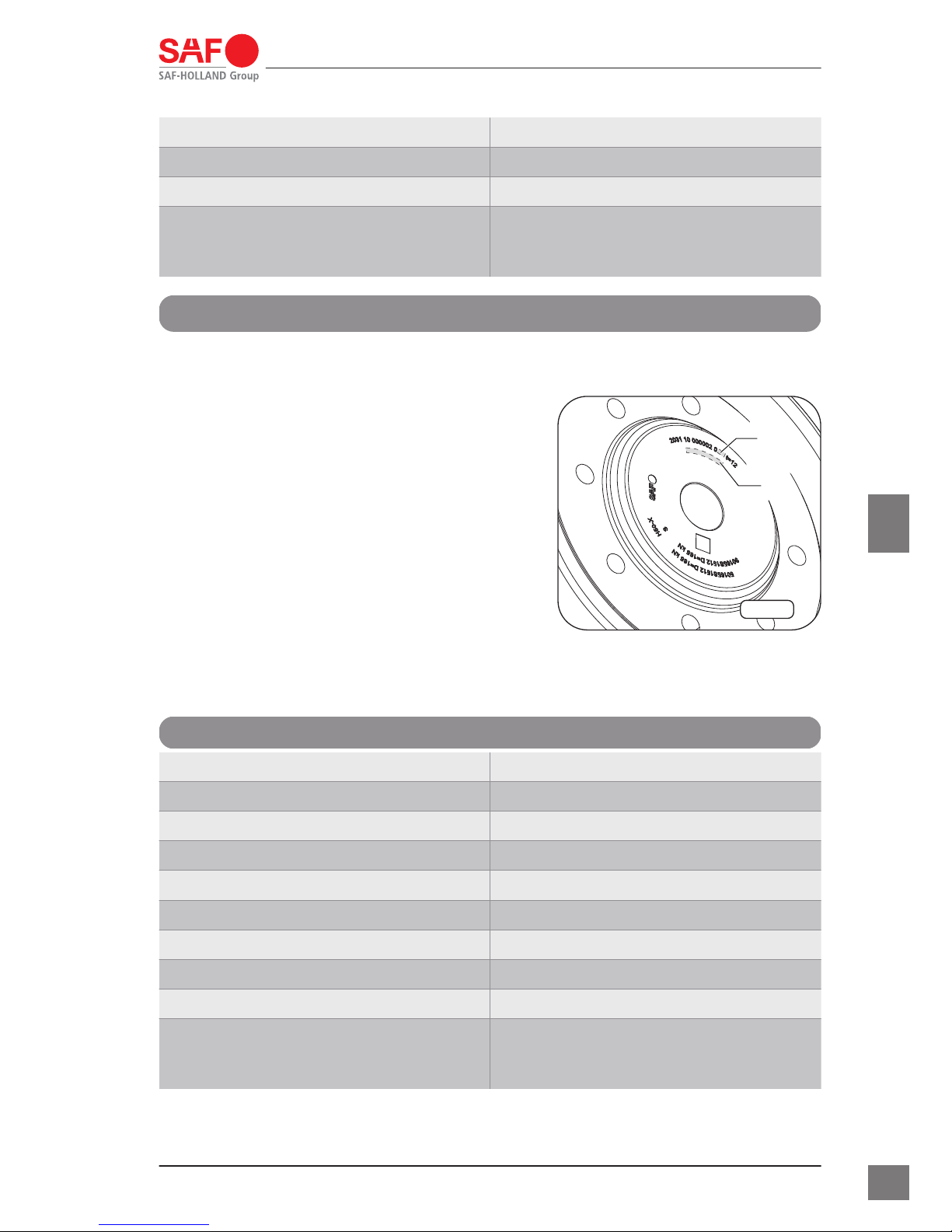
The details of the flange are engraved on
the inside –Arrow–, Fig. 2. The “D-value”
is given in kilonewton .
Flange details
Technical designation Value/detail
Manufacturer/brand SAF
permitted D-value: D = 165 kN
Design: 50165S1512 and 90165S1512
Class: H50–X or S
Part number: 2031 10 0000002 0
Revision: *1
Manufacturing site and serial number: *2
Trailer bolster plate thickness: t = 12
Data-Matrix-Code □: contains documentation and
manufacturing data, which are
centrally stored at SAF-HOLLAND
KP-0002
*1
*2
Fig. 2 · Flange example 50S15 or
90S15
1 Product data
5
XL-KP11695BM-en-DE Rev. A · 02.2015 · Errors and changes excluded · © SAF–HOLLAND
en
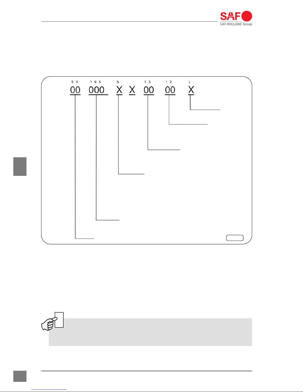
1.3 Type designation
marking
Following example is a description of the type marking Fig. 3. The letters
are marked with “X” and the numbers are marked with “0”.
KP-0011
2
3
4
5
6
( )
1
Fig. 3 · Explanation of the marking
1 Size:
• 50 = 2 inches
• 90 = 3.5 inches
2 D-value:
• 165 = 165 kN
• 320 = 320 kN
Note:
The D-value was not considered for the type approval.
3 Fastenings:
• S = with screws
1 Product data
6
XL-KP11695BM-en-DE Rev. A · 02.2015 · Errors and changes excluded · © SAF–HOLLAND
en
• M = with nuts
4 Circle diameter of part:
• 15 = 150 mm
• 18 = 180 mm
5 Semi-trailer bolster plate thickness:
• 06 = 6 mm
• 08 = 8 mm
• 10 = 10 mm
• 12 = 12 mm
• 16 = 16 mm
6 Marking of special types:
• L = steering
Note:
The thickness of the semi-trailer bolster plate is not considered
for the type approval.
Type overview
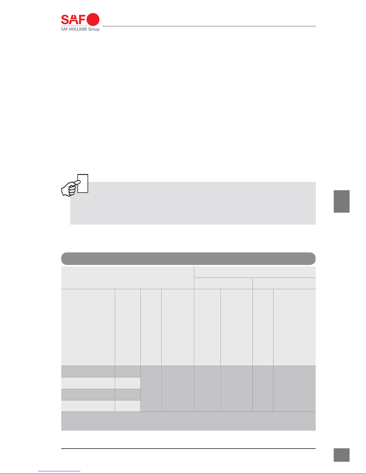
Type 50S15
Type 50S15
Installation with flange design
+GF+ HOLLAND
Design
Trailer plate thickness
in mm
D-value in kN
ECE approval no.
D-value in kN
type
D-value in kN
type
50165S1512 12
165
E1 55R–
01 2289
162.4 101 109 165 65
50165S1510 10
50165S1508 8
50165S1506 6
The pins of SAF type 50S15 can be installed with the corresponding flange
designs of +GF+ and HOLLAND.
1 Product data
7
XL-KP11695BM-en-DE Rev. A · 02.2015 · Errors and changes excluded · © SAF–HOLLAND
en
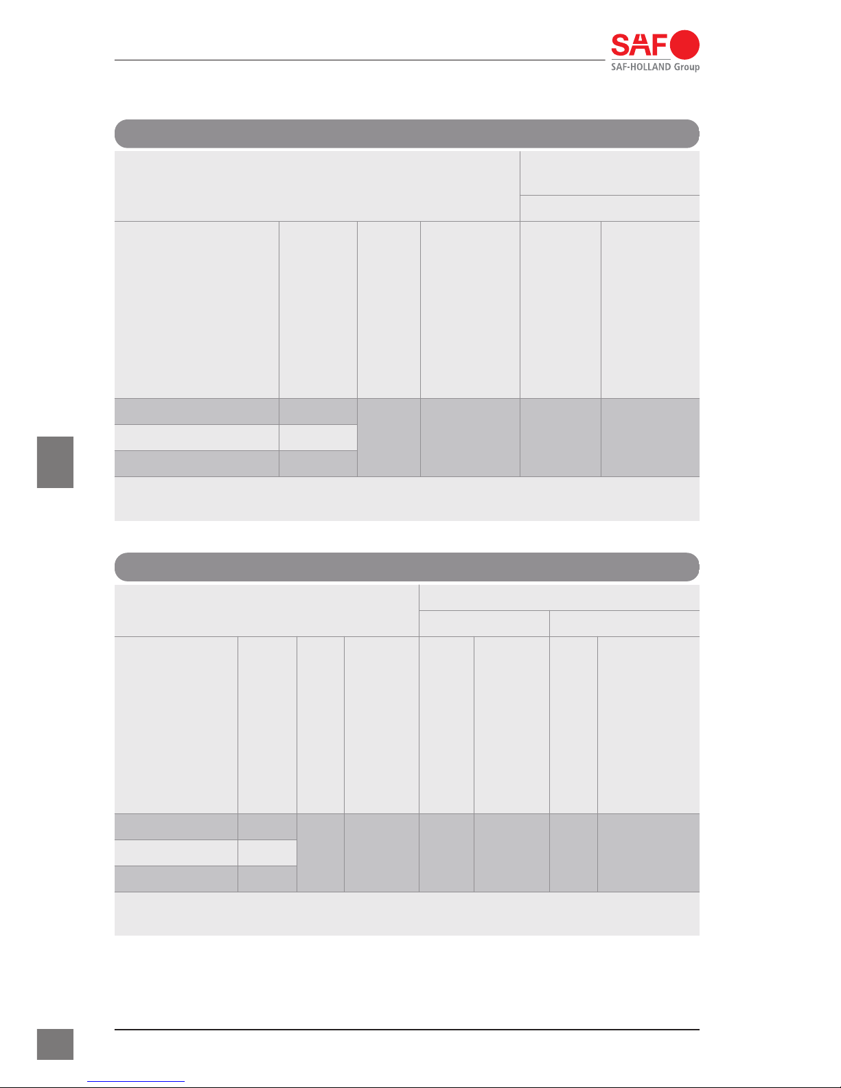
Type 50S15L
Type 50S15L
Installation with
flange design
+GF+
Design
Trailer plate thickness
in mm
D-value in kN
ECE approval no.
D-value in kN
type
50165S1512L 12
165
E1 55R–01
2422
162.4 101 10950165S1510L 10
50165S1508L 8
The pins of SAF type 50S15L can be installed with the corresponding flange
designs of +GF+.
Type 90S15
Type 90S15
Installation with flange design
+GF+ HOLLAND
Design
Trailer plate thickness
in mm
D-value in kN
ECE approval no.
D-value in kN
type
D-value in kN
type
90165S1512 12
165
E1 55R–
01 2371
162.4 101 169 165 6790165S1510 10
90165S1508 8
The pins of SAF type 90S15 can be installed with the corresponding flange
designs of +GF+ and HOLLAND.
1 Product data
8
XL-KP11695BM-en-DE Rev. A · 02.2015 · Errors and changes excluded · © SAF–HOLLAND
en
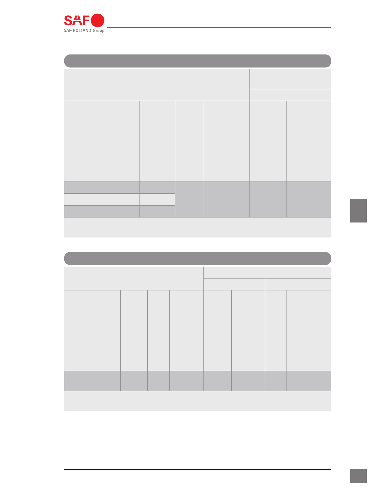
Type 90S15L
Type 90S15L
Installation with
flange design
+GF+
Design
Trailer plate thickness
in mm
D-value in kN
ECE approval no.
D-value in kN
type
90165S1512L 12
165
E1 55R–01
2421
162.4 101 16990165S1510L 10
90165S1508L 8
The pins of SAF type 90S15L can be installed with the corresponding flange
designs of +GF+.
Type 50S18
Type 50S18
Installation with flange design
+GF+ HOLLAND
Design
Trailer plate thickness
in mm
D-value in kN
ECE approval no.
D-value in kN
type
D-value in kN
type
50165S1816 16 165
E1 55R–
01 2418
162.4 102 022 165 66
The pins of SAF type 50S18 can be installed with the corresponding flange
designs of +GF+ and HOLLAND.
1 Product data
9
XL-KP11695BM-en-DE Rev. A · 02.2015 · Errors and changes excluded · © SAF–HOLLAND
en
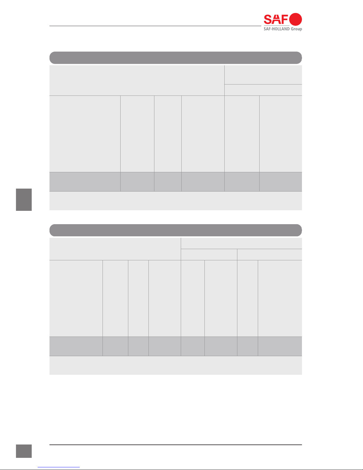
Type 50S18L
Type 50S18L
Installation with
flange design
+GF+
Design
Trailer plate thickness
in mm
D-value in kN
ECE approval no.
D-value in kN
type
50165S1816L 16 165
E1 55R–01
2428
162.4 102 022
The pins of SAF type 50S185L can be installed with the corresponding flange
designs of +GF+.
Type 90S18
Type 90S18
Installation with flange design
+GF+ HOLLAND
Design
Trailer plate thickness
in mm
D-value in kN
ECE approval no.
D-value in kN
type
D-value in kN
type
90320S1816 16 320
E1 55R–
01 2426
320 102 021 200 63
The pins of SAF type 90S18 can be installed with the corresponding flange
designs of +GF+ and HOLLAND.
1 Product data
10
XL-KP11695BM-en-DE Rev. A · 02.2015 · Errors and changes excluded · © SAF–HOLLAND
en
 Loading...