

Page 1
TEMINOX®
GL
Operating Instructions
Duoblock Burner
2021-06-22
BA-TEMINOX-GL-Duo2021-02
Page 2

The reproduction, distribution and utilization of this
the communication of its contents
to others without express authorization is prohibited.
Offenders will be held liable for the payment of
damages. All rights reserved in the event of the grant of
Copyright reserved
Technical Documentation SAACKE
Original Manual
document as well as
a patent, utility model or design.
Page 3

Technology with a Future
ch and development, ensure
Power of innovation, technical
perfection and reliability of all products
account for SAACKE’s technological
leadership. Competent project
management, comprehensive
service network stand for customer
proximity and partnership with a
guaranteed future within the industrial
worldwide -
For more than 80 years SAACKE has set
standards in economic, eco-friendly and
easy-to-service burner technology.
First-rate engineering and continuous
optimization of products and systems,
supported by extensive in-house
resear
requirements and sustain flexibility.
operational advice, and a worldwide
thermal market.
Page 4

Contents
TEMINOX®
GL
0 Contents
0 Contents ............................................................................................................................... 4
1 Safety .................................................................................................................................... 7
1.1 Documentation is a part of the product! ................................................................................................... 7
1.2 Symbols .................................................................................................................................................... 7
1.3 Safety in General ...................................................................................................................................... 8
1.4 Limit Values .............................................................................................................................................. 8
1.5 Authorized Use ......................................................................................................................................... 9
1.6 Limitation of Liability ................................................................................................................................. 9
1.7 Qualified Staff ......................................................................................................................................... 10
1.8 Transport and Interim Storage at Installation Site .................................................................................. 10
1.9 Danger from Hot Surfaces ...................................................................................................................... 10
1.10 Electrical Hazards................................................................................................................................... 11
1.11 Emergency Procedures .......................................................................................................................... 11
1.12 Explosion Protection in Potentially Explosive Atmospheres (ATEX) ..................................................... 11
1.13 Emergency Operation (Applies to Marine Plants Only).......................................................................... 11
1.14 Protective Clothing ................................................................................................................................. 11
2 Transport, Storage and Packing ....................................................................................... 12
2.1 Lifting Lugs ............................................................................................................................................. 12
2.2 Safety Instructions for Transport ............................................................................................................ 13
2.3 Checking the Delivery ............................................................................................................................ 13
2.4 Reporting Transport Damage ................................................................................................................. 13
2.5 Instructions for Storage .......................................................................................................................... 13
2.6 Disposal of the Packaging ...................................................................................................................... 14
2.7 Disposal of the Product .......................................................................................................................... 14
3 Design and Function ......................................................................................................... 15
4 Construction of the Refractory Brickwork ....................................................................... 20
4.1 Burner Head Variant C01 / C03 ............................................................................................................. 21
4.2 Burner Head Variant C02 ....................................................................................................................... 22
5 Mounting Instructions ....................................................................................................... 23
5.1 Mounting the Burner ............................................................................................................................... 23
5.2 Connecting Lines and Fittings ................................................................................................................ 25
6 Electrical Connections of the Burner ............................................................................... 27
7 Operation ............................................................................................................................ 28
7.1 Preparing the Heat Generator ................................................................................................................ 28
7.2 Preparing the Burner .............................................................................................................................. 28
7.3 Starting the Burner ................................................................................................................................. 28
Technical Documentation
4 / 78
BA-TEMINOX-GL-Duo2021-02 2021-06-22
Page 5

TEMINOX®
GL Contents
7.4 Controlled Operation .............................................................................................................................. 28
7.5 Switching Off the Burner ........................................................................................................................ 28
7.6 Service Interruption due to Fault ............................................................................................................ 29
8 Functional Schematic ........................................................................................................ 30
9 Maintenance / Cleaning ..................................................................................................... 34
9.1 General Information ................................................................................................................................ 34
9.2 Preparing Maintenance Work ................................................................................................................. 35
9.2.1 Periodical Maintenance (Fault not Acute) ............................................................................... 35
9.2.2 Maintenance after a Fault has Interrupted the Operation ....................................................... 36
9.3 Maintenance Intervals ............................................................................................................................ 36
9.4 Maintenance of General Components.................................................................................................... 37
9.4.1 Checking Supply Pressures .................................................................................................... 39
9.4.2 Cleaning the Flame Scanner / Performing a Function Test .................................................... 40
9.4.2.1 SAACKE FLUS 06 UV / FLS 09 UV ................................................................... 40
9.4.2.2 F 200 K2 ............................................................................................................. 41
9.4.3 Checking the Air Pressure Monitor ......................................................................................... 42
9.4.4 Checking the Protective Grating of the Fan ............................................................................ 43
9.4.5 Lubricating the Bearings of the Fan Motors (>75 kW Fan Output) ......................................... 43
9.4.6 Checking the Force Transmitter .............................................................................................. 43
9.4.7 Checking the Ignition Cables and Plug-and-Socket Connections .......................................... 43
9.4.8 Checking the Ignition Systems ZAP(ZDAP) and ZA0(ZDA0) ................................................. 44
9.5 Maintenance of Components Relevant to the Oil Operation Mode ........................................................ 45
9.5.1 Cleaning the Dirt Trap ............................................................................................................. 46
9.5.2 Checking the Fuel Lines Outside the Burner .......................................................................... 46
9.6 Maintenance of Components Relevant Especially to the Gas Operation .............................................. 47
9.7 After Completion of the Maintenance Work ........................................................................................... 47
10 Troubleshooting ................................................................................................................ 48
10.1 Troubleshooting (Gas Operation) ........................................................................................................... 48
10.2 Troubleshooting (Oil Operation) ............................................................................................................. 52
11 Dimensions / Types ........................................................................................................... 55
11.1 Arrangement of the Ignition Medium and Fuel Fittings .......................................................................... 55
11.2 Basic Dimensions ................................................................................................................................... 58
11.3 Weight .................................................................................................................................................... 59
11.3.1 Mixing System ......................................................................................................................... 59
11.3.2 Integrated Burner Control System (Optional) ......................................................................... 59
11.3.3 Motor Control (Optional) ......................................................................................................... 59
11.4 Center of Gravity .................................................................................................................................... 60
11.5 Position of the Fuel Inlets ....................................................................................................................... 61
11.6 Position of the Air Inlet Connection ........................................................................................................ 65
11.7 Burner Mounting Plate ............................................................................................................................ 66
Technical Documentation
2021-06-22
BA-TEMINOX-GL-Duo2021-02 5 / 78
Page 6

Conte
nts TEMINOX®
GL
11.8 Minimum Distances ................................................................................................................................ 68
11.8.1 All Duoblock Burners .............................................................................................................. 68
11.8.2 “Outer” Ignition and Fuel Fittings ............................................................................................ 69
11.8.3 “Inner” Ignition and Fuel Fittings ............................................................................................. 70
11.9 Connection Dimensions ......................................................................................................................... 71
11.10 Tightening Torque for Mounting Screws ................................................................................................ 72
12 Technical Data ................................................................................................................... 73
12.1 Capacity and Turndown Ratio ................................................................................................................ 73
12.2 Requirements for Fuels and Further Media ........................................................................................... 74
12.3 Distances of Fuel Supply System Components ..................................................................................... 75
12.4 Electrical Data ........................................................................................................................................ 75
12.5 Permitted Mounting Positions ................................................................................................................. 76
12.6 Acoustic Emissions................................................................................................................................. 77
6 / 78
Technical Documentation
BA-TEMINOX-GL-Duo2021-02 2021-06-22
Page 7
TEMINOX®
GL
Safety
1 Safety
1.1 Documentation is a part of the product!
This document is an integral part of the product. It must be retained for the entire
service life of the product. Make this document available to the staff responsible for
the work described in it. Add any updates you receive later from SAACKE to the
document.
Help us improve this documentation!
We appreciate any feedback that improves the quality of our documentation. You
will find our address on the back of this document.
1.2 Symbols
Especially important information in this document is highlighted by the
corresponding symbols:
Warning!
The industrial safety symbol identifies safety instructions whose purpose is to
prevent physical injury or death. Follow these safety instructions carefully and be
especially cautious during the work/procedures they refer to.
Warning! Risk of death from electric shock!
The electricity symbol identifies safety instructions whose purpose is to prevent
physical injury or death from electric shock. Follow these safety instructions
carefully and be especially cautious during the work/procedures they refer to.
Caution!
The caution symbol identifies all safety warnings whose purpose is to prevent
damage or destruction of the product and/or other plant components.
2021-06-22
Note
This points to information or notes that are especially useful.
Technical Documentation
BA-TEMINOX-GL-Duo2021-02 7 / 78
Page 8

Safety
TEMINOX®
GL
1.3 Safety in General
The "Safety" chapter gives you an overview of the safety aspects you must pay
attention to in order to work with the product safely. Any individual who assembles,
installs, mounts, commissions, operates and/or does maintenance on the product
described must read and follow the instructions in this chapter carefully to avoid
physical injury and material damage. Your safety is at stake.
In addition to these general safety instructions you will find specific safety
instructions in the product documentation related to individual actions or
procedures.
Only if you follow all of the safety instructions will you be able to provide the best
possible protection for yourself, your colleagues and the environment by ensuring
that the product functions safely and reliably.
In addition to this, it is imperative that you comply with the accident prevention and
safety regulations of the country you are working in.
1.4 Limit Values
The following products (apart from the burner) are considered as further
subsystems of a plant:
Heat generator / air supply system / flue gas system
Fuel supply system
Burner control system
Other plant components that are not part of the burner (e.g. sound absorbing
These subsystems are required to operate the plant but they are not an integral
part of the burner described in the present document and may vary depending on
the plant. For this reason, the present burner documentation does not include any
concrete contents on the other subsystems of the plant.
system, emissions-reducing systems)
We assume that the burner and the other subsystems are properly mounted and
electrically connected before they are commissioned and that the supply of the
burner with the fuel agreed on in the contract is ensured. We also assume that the
other subsystems comply with the relevant standards/regulations, that they are
compatible with the burner and have been tested for proper operation.
The burner must be integrated into a coherent plant environment. For instructions
on integrating the burner into a coherent plant environment, please refer to the
chapters "Furnace Dimensions" and "Burner Selection" in the planning
documentation. For any information required for mounting the burner, connecting
the burner to the electric system and for the construction of the refractory
brickwork, please refer to the planning documentation and to the operating
instructions.
The plant authorities must ensure compliance with the country-specific accident
prevention and safety regulations. They must also ensure that the work
environment (e.g. boiler house) complies with the regulations. We recommend that
the plant authorities compile operating instructions for the entire work environment.
The present document and all other manufacturer´s documentation for the plant
components should be used as a basis for these operating instructions.
Technical Documentation
8 / 78
BA-TEMINOX-GL-Duo2021-02 2021-06-22
Page 9

TEMINOX®
GL
Safety
1.5 Authorized Use
The burner is exclusively designed to generate heat within the performance data
specified in the Technical Data by combusting the fuel specified on the rating plate.
The burner must be integrated into a coherent plant environment (fuel supply
system, heat generator etc.) (refer to chapter 1.4).
The energy generated by the burner, must be taken off, also during
commissioning.
To ensure proper operation of the burner, the pressure at the installation site must
not be negative relative to the atmosphere. The suction opening of the fan must be
free to ensure that it can draw in sufficient air.
Before the burner may be used for controlled operation, it must be commissioned
(with regard to its combustion performance). Only commissioning experts (refer to
"Qualified Staff") are permitted to commission the burner.
The commissioning expert is responsible for achieving proper combustion at all of
the firing rates and for ensuring that all the safety equipment (monitors etc.) are set
correctly. He/she must record all the values set in an approval and measurement
report and make it available to the plant authorities.
The settings made during commissioning must not be changed later on. Exception:
If the operating conditions change at a time following commissioning (e.g. due to
changed fuel properties or the plant environment), a commissioning expert must
check the settings and adjust them, if required. Again, the values set must be
recorded in an approval and measurement report.
The burner is fitted with safety equipment and has been tested for safety and
accepted. It may be operated only if the entire safety equipment has been adjusted
correctly and is in operation. The following is considered as safety equipment:
safety interlock circuits and all the associated components, all the other monitors
as well as construction-related protective measures such as safety fencing and
warning signs.
It is prohibited to modify or disable safety equipment unless the documentation
explicitly instructs you to disable and/or dismount such equipment temporarily. If
this should be required, e.g. for maintenance, the safety equipment must be
mounted and/or enabled again before the burner is taken into operation again. As
a rule, warning signs must never be covered or removed.
Unauthorized reconstruction and modification of the burner is prohibited. Only
original spare parts may be used! The use of third-party accessories must explicitly
be approved by SAACKE.
Comply with the instructions and regulations in the documentation in all the phases
of life of the burner. This applies especially to the burner maintenance (adhering to
the intervals for inspection and maintenance and for replacing safety-related
components).
To ensure operability, safety and economic efficiency, the plant must be inspected
by the manufacturer and/or authorized and trained personnel once a year. A
service agreement is recommended. SAACKE Service is at your disposal for more
detailed information.
1.6 Limitation of Liability
Any use deviating from the conditions specified above is considered as
unauthorized.
2021-06-22
SAACKE does not assume liability for damage resulting from unauthorized use.
Such use is at the risk of the operator/plant authorities.
Technical Documentation
BA-TEMINOX-GL-Duo2021-02 9 / 78
Page 10
Safety
TEMINOX®
GL
1.7 Qualified Staff
Warning!
Risk of injury and property damage due to improper operation!
The plant authorities must ensure that only qualified and authorized personnel uses
the product.
In terms of the present documentation, the term qualified staff refers to persons
who have been trained in handling the described product and are authorized by the
plant authorities to mount, commission, operate and/or service the product.
The burner may only be commissioned by personnel especially trained and
certified to do so for the burner and the plant components concerned
("commissioning experts“). SAACKE will provide the training and certification for
the burner; either SAACKE or the respective manufacturer will provide the training
and certification for the other plant components.
1.8 Transport and Interim Storage at Installation Site
Risk of injuries if the burner falls over
If the burner falls over, it can cause serious injuries!
Always follow the transport and storage instructions.
1.9 Danger from Hot Surfaces
Warning! Risk of burns from hot surfaces!
If the burner is operated with preheated air, steam or preheated oil, the following
safety measures must be taken to avoid injury:
Burners operating with preheated air are designed to be insulated.
Protect all accessible surfaces with insulation (for instance, in the form of mineral
insulation), so that the surface temperature does not exceed 50 °C (in
accordance with DIN EN 563) and/or protect all accessible surfaces with a
protection plate.
Burners and associated components operated with steam or preheated oil that
were not insulated ex works upon delivery must also be insulated appropriately.
Nevertheless, ensure that all hazardous areas are equipped with clearly visible
warning signs to draw the personnel's attention to the risk of injury arising from
contact with hot surfaces.
Wear appropriate protective clothing when performing any work on the burner and
always comply with national accident prevention and safety regulations.
Warning! Risk of burns from hot surfaces!
The FGR line must be insulated at burners that are operated with recirculated flue
gas.
10 / 78
Technical Documentation
BA-TEMINOX-GL-Duo2021-02 2021-06-22
Page 11
TEMINOX®
GL
Safety
1.10 Electrical Hazards
Warning! Risk of death from electric shock!
Damaged lagging or live components that are not covered correctly present a risk
of death from electric shock!
Warning! Risk of death from electric shock!
Carelessness can lead to an electric shock.
This is why when you work with electrical equipment, you must always first:
1. Disconnect each piece of equipment from the mains.
2. Secure it to prevent it from being switched back on.
3. Check that the equipment is de-energized.
4. Ground the equipment and short-circuit it.
5. Cover other components/equipment nearby that are energized.
6 Secure the danger zone, for example by blocking it off and/or putting up a
1.11 Emergency Procedures
conspicuous danger sign that no one can overlook.
In the case of danger:
Press the "Emergency stop button" of the plant and cut off the fuel supply!
1.12 Explosion Protection in Potentially Explosive Atmospheres (ATEX)
If the product is to be used in potentially explosive atmospheres, the plant
authorities must ensure that the product is integrated into an appropriate explosion
protection concept in compliance with directive 1999/92/EC.
1.13 Emergency Operation (Applies to Marine Plants Only)
SAACKE burners used in marine plants feature an emergency operation function
to meet the requirements of the corresponding classification societies. For more
information, please refer to the emergency operation documents that are part of
the plant documentation.
1.14 Protective Clothing
Warning!
When performing any work, always wear appropriate protective clothing that
complies with the accident prevention and safety regulations of the country you are
working in.
Transport
2021-06-22
Technical Documentation
BA-TEMINOX-GL-Duo2021-02 11 / 78
Page 12
Transport, Storage and Packing
TEMINOX®
GL
TMX029
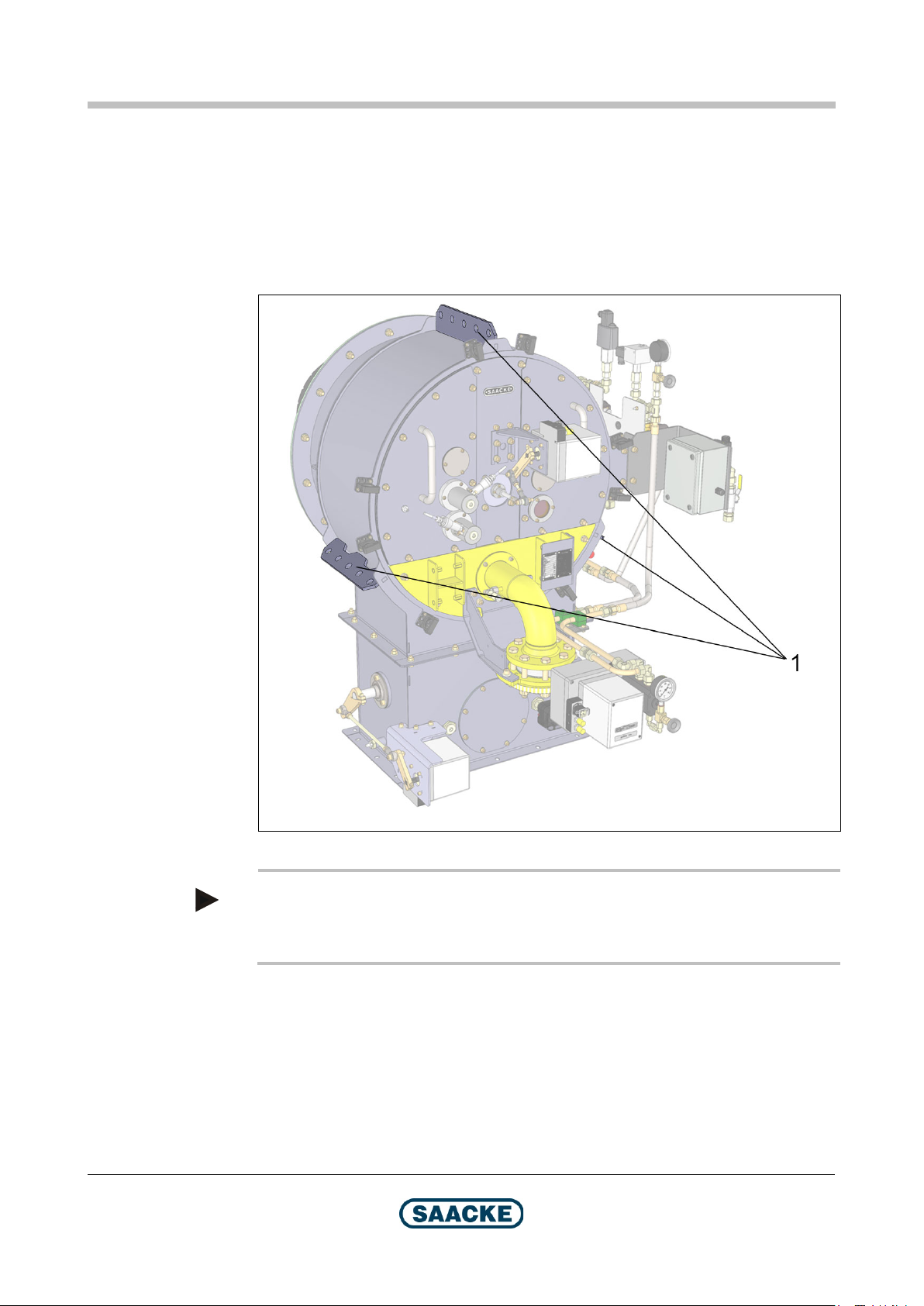
2 Transport, Storage and Packing
The burner is delivered screwed onto a transport rack and secured with holding
straps.
Remove the transport rack before mounting the burner onto the heat generator.
2.1 Lifting Lugs
12 / 78
Fig. 1: Lifting lugs
Note
Observe the information on weight and center of gravity in chapter "Dimensions /
Types".
Technical Documentation
BA-TEMINOX-GL-Duo2021-02 2021-06-22
Page 13
TEMINOX®
GL
Transport, Storage and Packing
2.2 Safety Instructions for Transport
Warning! Risk of accidents during transport!
There is the risk of accidents during burner transport due to the heavy weight.
Do not stand under suspended loads.
Always use the appropriate aids when loading the burner (e.g. forklift or
crane).
Warning! Risk of injuries from hoists too weak for the load!
Hoists or lifting equipment that are too weak for the load can tear.
Always select hoists or lifting equipment with sufficient load bearing capacity.
Use only tested and reliable hoists and lifting equipment, such as:
– Shackles, e.g. according to DIN 82101.
– Sling chains, e.g. according to DIN 5687 Product Grade 8
Caution!
The improper use of means of transport and tools (e.g. forklift or crane) bears the
risk of damaging the burner or burner components.
2.3 Checking the Delivery
SAACKE products are packed and checked before they leave the factory.
When the product is delivered, first check whether the packaging is intact. This
would be the first indication that it has been transported correctly.
Check the product for transport damage.
2.4 Reporting Transport Damage
If damage has occurred during transport, follow these procedures:
Record the transport damage on the freight documents and take a
photograph and/or make a sketch of it.
Have the person responsible for the delivery (for example the truck driver)
confirm that the damage was noticed by signing the freight documents.
Report the transport damage right away to SAACKE or whichever company
supplied the product.
2.5 Instructions for Storage
Only store the burner on the pallet or in the crate that it was delivered on/in.
Store the burner on safe and firm ground.
Keep all components, especially electrical, pneumatic and hydraulic components,
dry, free of dust and at their correct temperature during storage. The relative
humidity must be below 80 %.
2021-06-22
Protect the burner with appropriate covering in the case of a long period of
inactivity. Preserve all metal surfaces.
Technical Documentation
BA-TEMINOX-GL-Duo2021-02 13 / 78
Page 14

Transport, Storage and Packing
GL
2.6 Disposal of the Packaging
Dispose of all packaging correctly and ecologically.
When you do it, comply with the waste disposal regulations of the country in which
you are working.
2.7 Disposal of the Product
At the end of its service life the product must be disposed of correctly and
ecologically.
When you do it, comply with the waste disposal regulations of the country in which
you are working.
TEMINOX®
14 / 78
Technical Documentation
BA-TEMINOX-GL-Duo2021-02 2021-06-22
Page 15
TEMINOX®
GL
Design and Function
TMX192
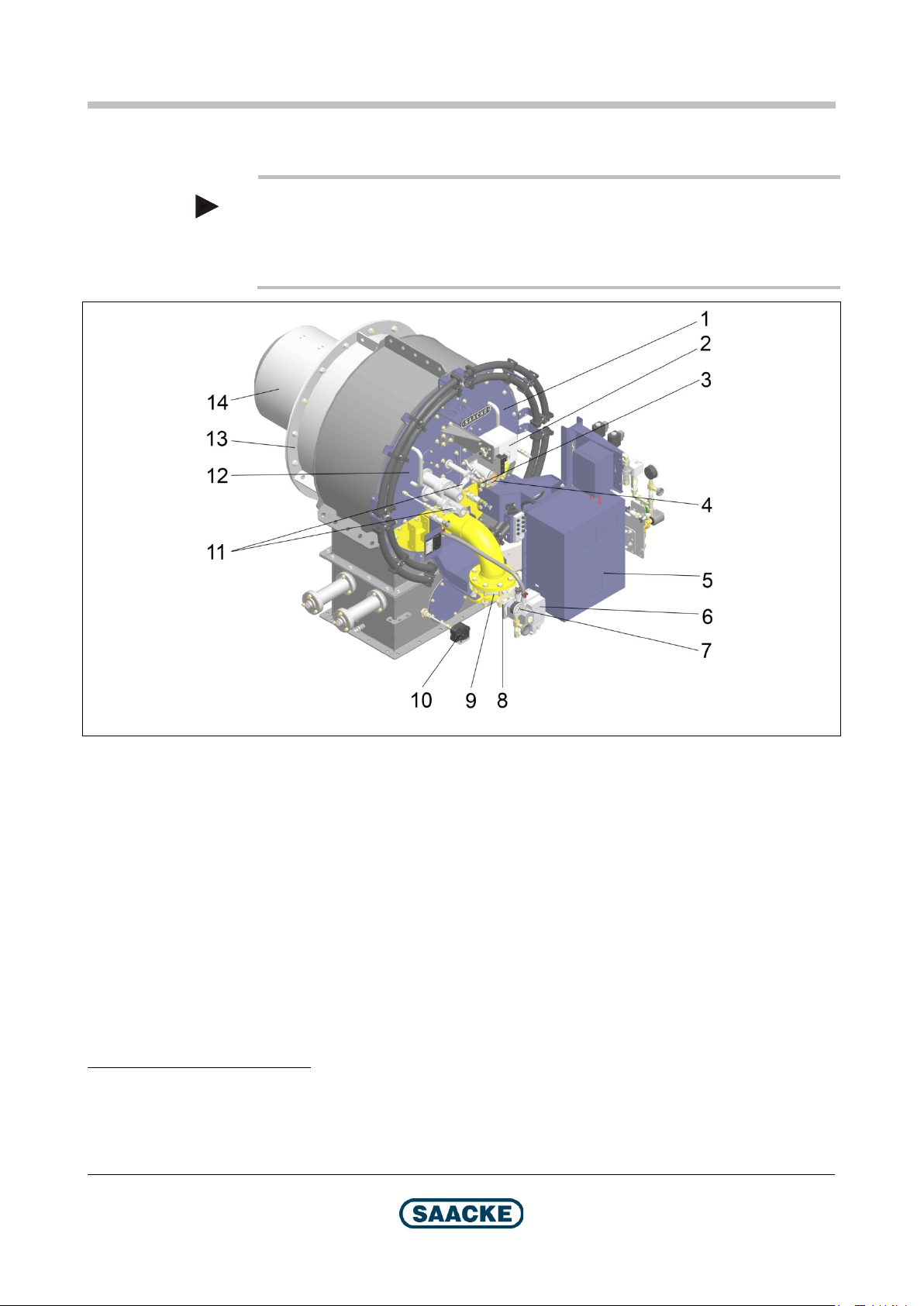
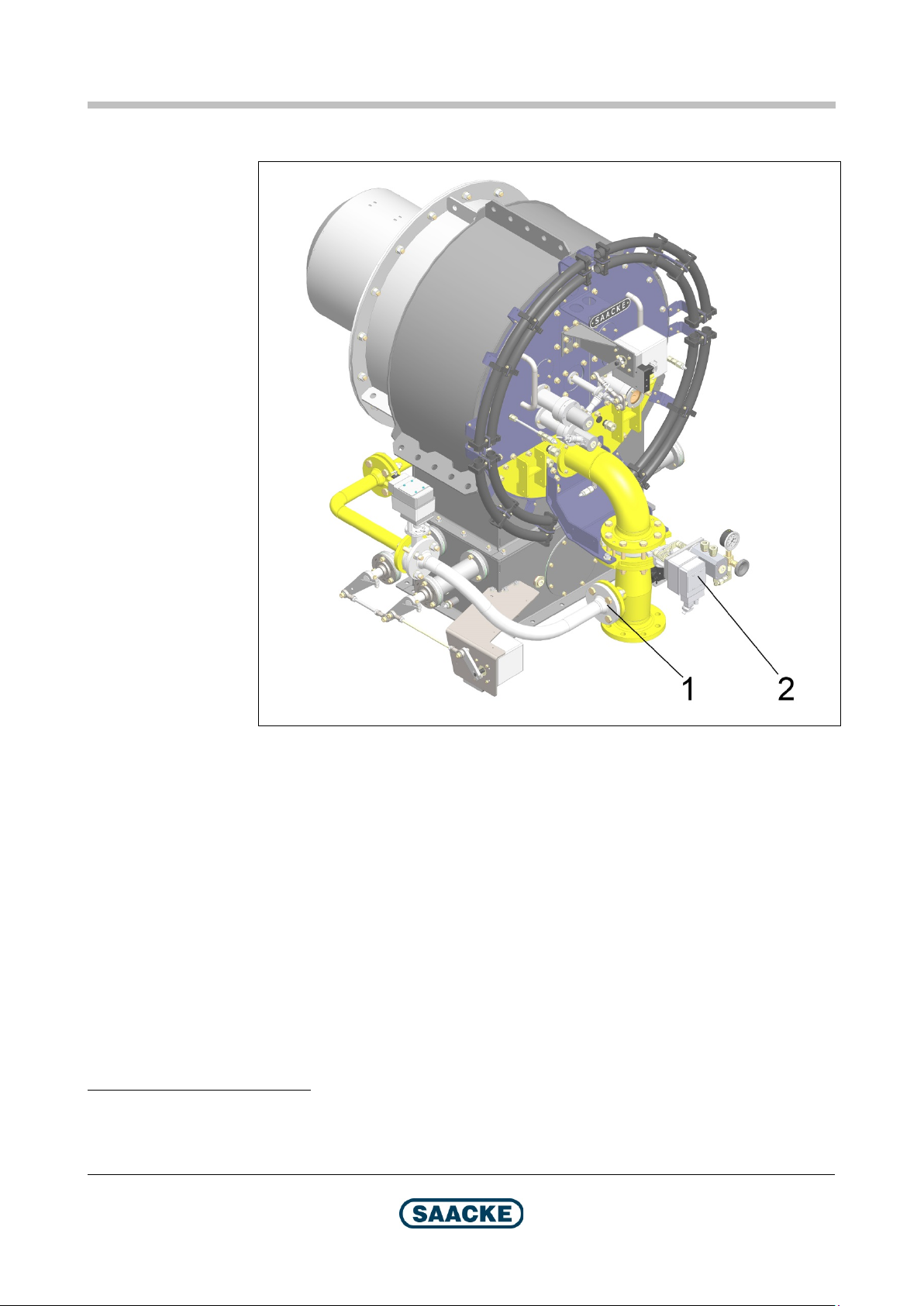
3 Design and Function
Note
A burner with standard equipment is shown. The equipment may vary depending
on the plant. As several burner head variants are possible, the presentation of the
burner head may differ.
Fig. 2: Burner components (1)
1 Right-hand maintenance cover
2 Servomotor for stabilizing disk retract mechanism
3 Driving linkage for stabilizing disk retract mechanism
4 Inspection glass
5 Component connection box / control box for optional integrated burner control system
6 Servomotor for oil flow controller / gas control damper
7 Return line pressure gauge (with manual shut-off fitting)
8 Power transmitter for oil flow controller / gas control damper
9 Gas control damper
10 Pressure monitor (L) for combustion air
11 Flame scanner (here: optional variant with 2 flame scanners)
12 Left-hand maintenance cover
13 Flange
14 Burner head
1
2
1
With TEMINOX G burners with burner head variant C02, a manual stabilizing disk retract mechanism is
installed as the standard. The servomotor is only available as an option for this variant.
2
Only TEMINOX GL (dual-fuel burner)
Technical Documentation
2021-06-22
BA-TEMINOX-GL-Duo2021-02 15 / 78
Page 16
Design and Functi
on TEMINOX®
GL
TMX193
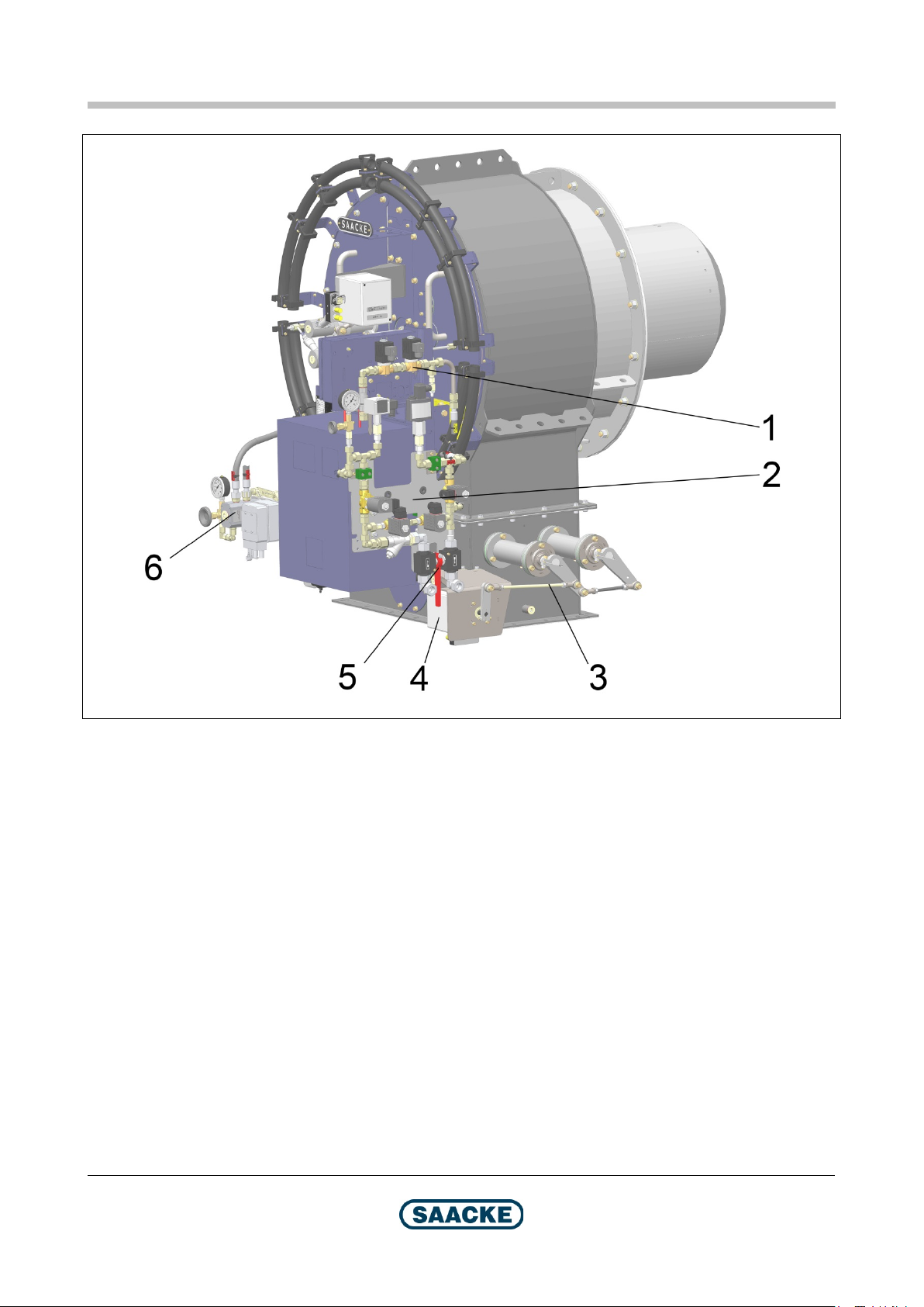
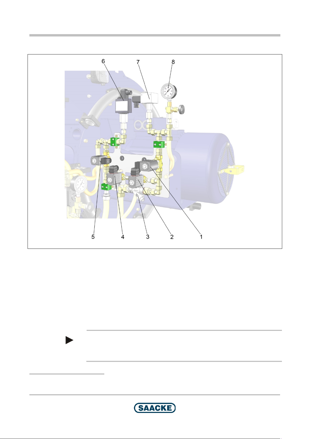
Fig. 3: Burner components (2)
1 Ignition valves (here: manual shut-off fitting in open position)
2 Oil fittings block (see separate figure)
3 Driving linkage for air control dampers
4 Servomotor for air control dampers
5 Manual shut-off fitting supply line / return line (mechanically coupled) (here: open position)
6 Oil flow controller
16 / 78
Technical Documentation
BA-TEMINOX-GL-Duo2021-02 2021-06-22
Page 17
TEMINOX®
GL
Design and Function
TMX254
Burner with Controlled Primary Gas (optional3)
Fig. 4: Burner with controlled primary gas4
1 Primary gas control damper
2 Servomotor for primary gas control damper
3
Standard with burner head variant C03
4
Oil fittings and component connection box are hidden for a better overview
2021-06-22
Technical Documentation
BA-TEMINOX-GL-Duo2021-02 17 / 78
Page 18
Desig
n and Function TEMINOX®
GL
TMX015
Oil Fittings Block
Fig. 5: Oil fittings block5
1 Rapid shut-off valve supply line
2 Rapid shut-off valve control line supply line
3 Dirt trap
4 Rapid shut-off valve control line return line
5 Rapid shut-off valve return line
6 Pressure monitor (H)
7 Pressure monitor (L)
8 Pressure gauge for supply flow pressure (with manual shut-off fitting)
Not illustrated: Manual shut-off fitting supply line / return line (see figures above)
Note
Depending on the arrangement of the ignition medium and fuel fittings, the oil
fittings block can have a laterally inversed design.
5
The example shows a monoblock burner, the duoblock burner has a similar design
Technical Documentation
18 / 78
BA-TEMINOX-GL-Duo2021-02 2021-06-22
Page 19

TEMINOX®
GL
Design and Function
TMX194
Position of the Rating Plate and the Plate for Variant Designation
2021-06-22
Fig. 6: Position of the rating plate and the plate for variant designation
1 Rating plate and plate for variant designation
Technical Documentation
BA-TEMINOX-GL-Duo2021-02 19 / 78
Page 20
Construction of the Refractory Brickwork
TEMINOX®
GL
4 Construction of the Refractory Brickwork
Before the burner can be mounted on the heat generator, refractory brickwork must
be constructed in keeping with the specifications in the present chapter.
The fireproof material for the refractory brickwork should have a AL
content of
2O3
at least 60 % and a spalling resistance of at least 15.
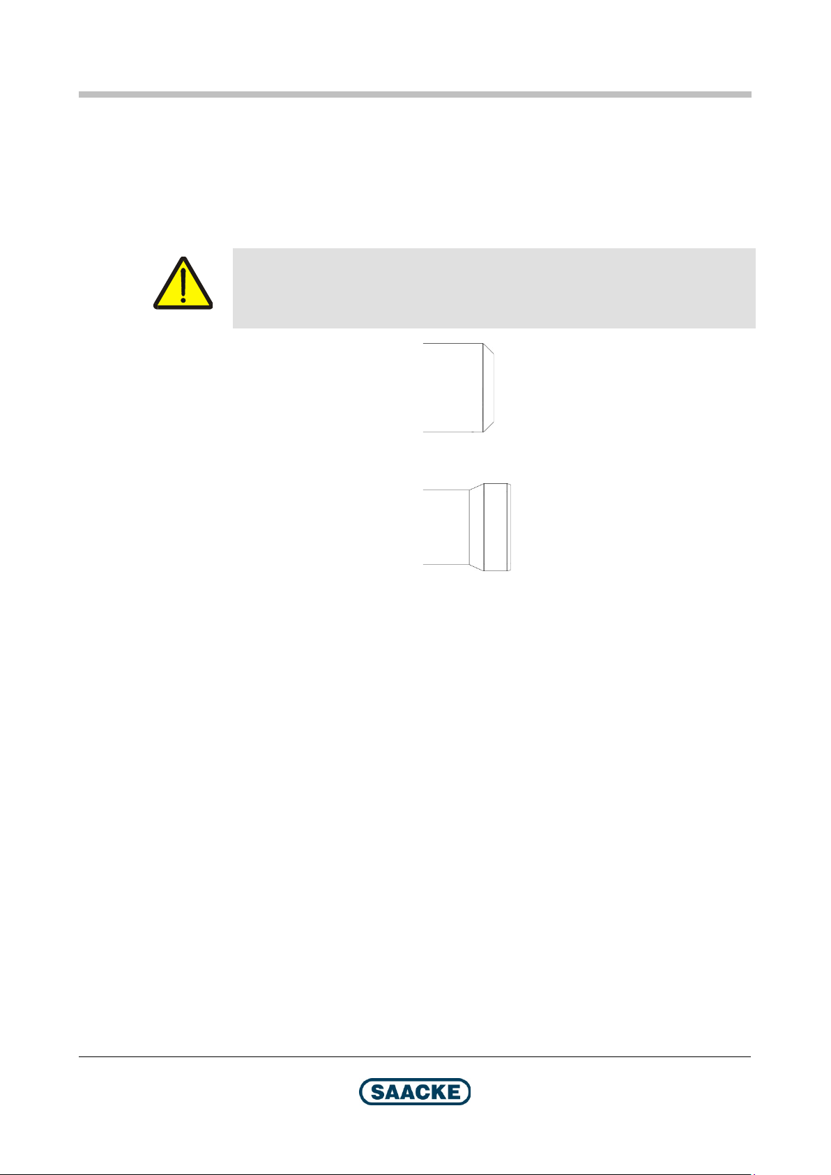
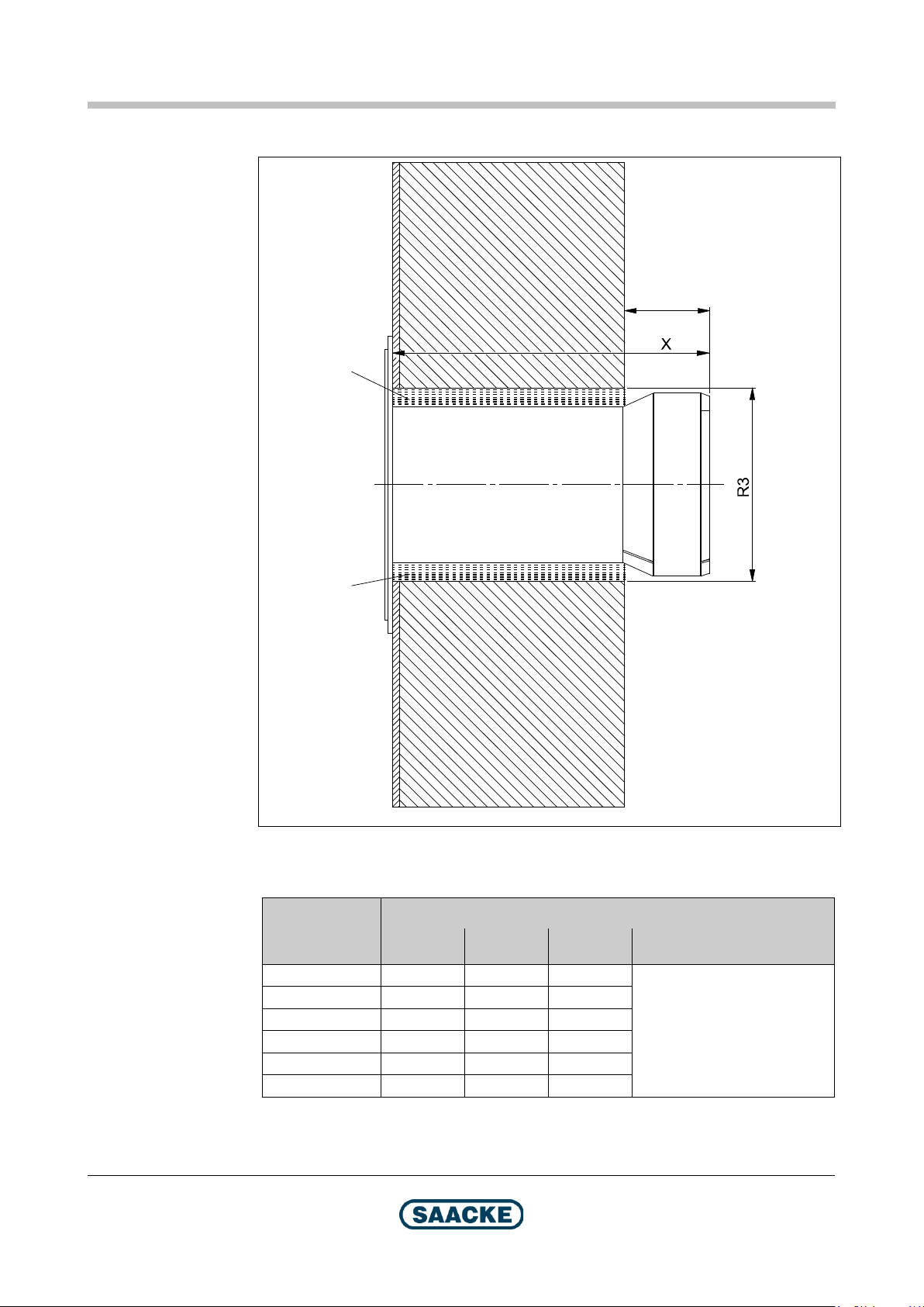
Warning!
The refractory brickwork must be parallel to the burner mounting plate and at right
angle to the center line of the burner, as shown in the figure.
With this burner head variant
please continue with chapter “Burner Head Variant C01 / C03”.
With this burner head variant
please continue with chapter “Burner Head Variant C02”.
20 / 78
Technical Documentation
BA-TEMINOX-GL-Duo2021-02 2021-06-22
Page 21
TEMINOX®
GL
Construction of the Refractory Brickwork
TMX053
W
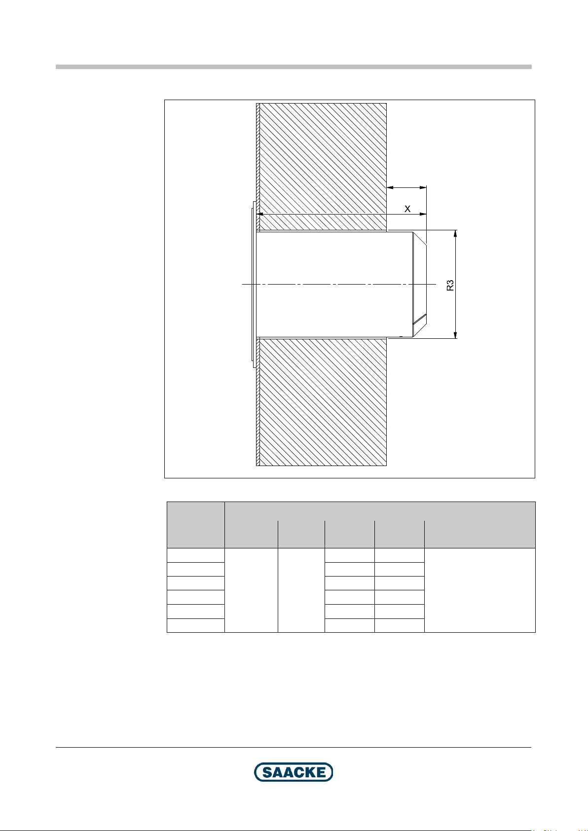
4.1 Burner Head Variant C01 / C03
Fig. 7: Refractory brickwork
Dimensions in mm
Burner size
W
Corrugated tube W Plain tube
50
70 475 470
100 480 475
140 480 475
200 480 475
280 495 490
≥130
≥130
and
≤160
X
Monoblock
burners
475 -
X
Duoblock
burners
R3
See chapter “Dimensions /
Types”, section “Burner
Mounting Plate”, dimension
MBP1 (monoblock burners) /
DBP1 (duoblock burners)
Technical Documentation
2021-06-22
BA-TEMINOX-GL-Duo2021-02 21 / 78
Page 22
Construction of the Refractory Brickwork
GL
4.2 Burner Head Variant C02
TMX043
X
burners
X
burners
W
1
1
TEMINOX®
Fig. 8: Refractory brickwork
1 Ceramic fibre mat (see chapter “Mounting Instructions”)
Dimensions in mm
Burner size
50 110 470 -
70 130 490 485
100 145 510 505
140 165 525 520
200 190 550 545
280 215 575 570
W
Monoblock
Duoblock
R3
See chapter “Dimensions / Types”,
section “Burner Mounting Plate”,
dimensions
MBP1 (monoblock burners) /
DBP1 (duoblock burners)
Transport
Technical Documentation
22 / 78
BA-TEMINOX-GL-Duo2021-02 2021-06-22
Page 23
TEMINOX®
GL Mounting Instructions
5 Mounting Instructions
Warning! Risk of injury and property damage due to the weight of the burner
and the fan!
For all the work described in the following, always follow the instructions and safety
instructions in the chapter "Transport, Storage and Packaging" before starting with
any of the tasks described here!
Caution! Faulty mounting of the burner possible!
The correct construction of the refractory brickwork (refer to the chapter entitled
"Construction of the Refractory Brickwork") is a requirement for mounting the
burner.
Note
Observe section “Burner Mounting Plate” (chapter “Dimensions / Types“).
Caution!
There may still be a small amount of oil from the pressure test in the oil-carrying
lines. Keep an oil drip tray ready during mounting and dispose of any oil correctly
and ecologically.
Warning! Health hazard due to ceramic fiber material!
Sealing cords and fiber plates for sealing contain ceramic high-temperature mineral
fibers, which may be a health hazard in the case of direct contact or if fiber dust is
inhaled. When handling sealing cords or fiber plates, wear appropriate protective
clothing (overall that fits loosely on your throat and wrists, gloves, safety goggles
with side shields, FFP2 respirators).
Caution!
The heat generator is subject to thermal expansion. Therefore flexible connectors
must be fitted between all fixed lines and ducts and the burner. When connecting
the flexible connectors, note the direction of the expansion.
5.1 Mounting the Burner
Note
With this burner head variant
please wind the supplied ceramic fiber mat around the thinner, cylindrical part of
the burner head before installing the burner (see chapter “Construction of the
Refractory Brickwork”)
2021-06-22
Technical Documentation
BA-TEMINOX-GL-Duo2021-02 23 / 78
Page 24
Mounting Instructions
TEMINOX®
GL
TMX049
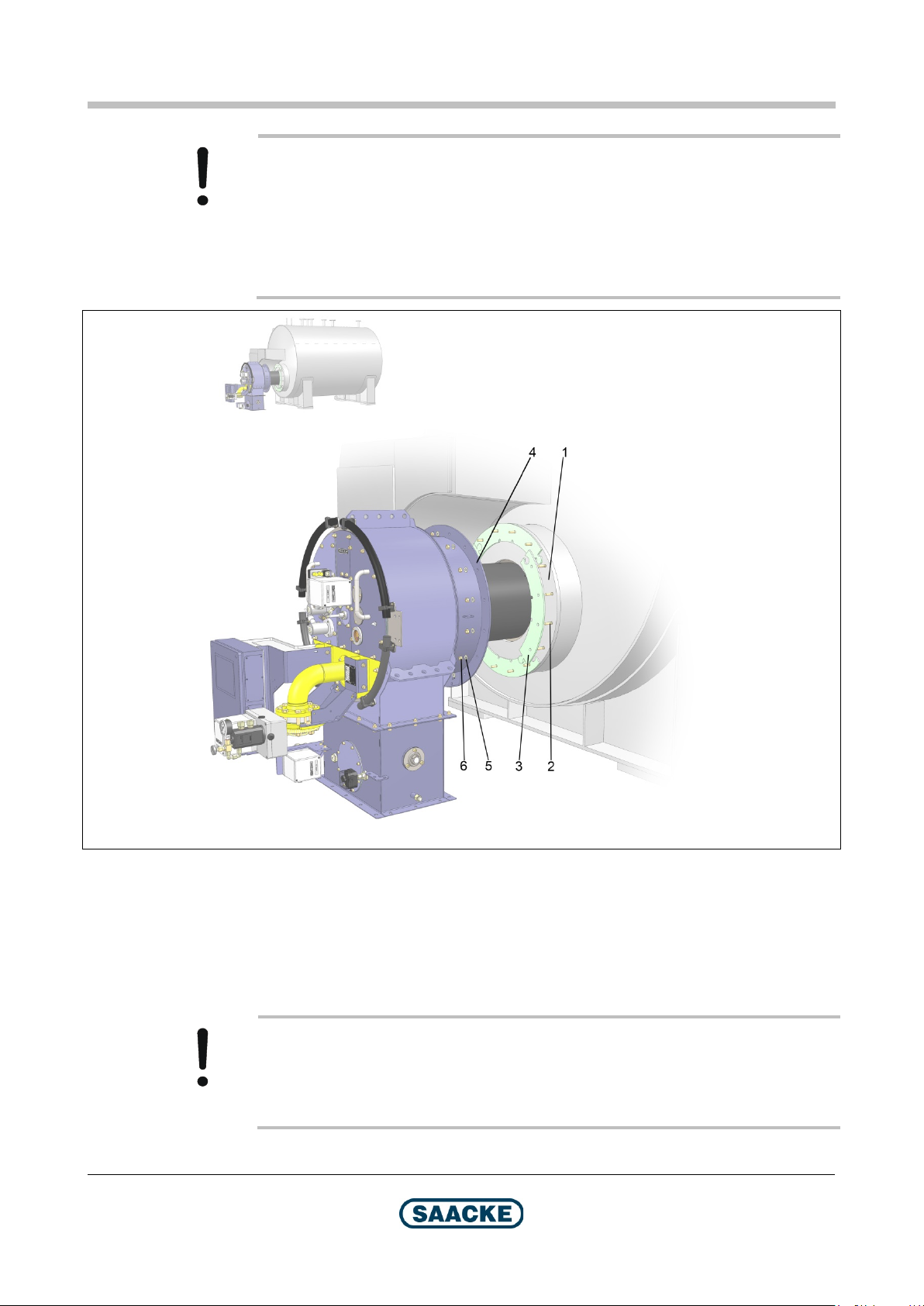
Caution! Faulty mounting of the burner possible!
Take into consideration the entry position of the combustion air when mounting the
burner: In the figure, position 0° is shown as an example. This position differs
depending on the plant configuration!
In addition, please have in mind that that gas connection module must always be
in position 0°, independent of the plant configuration.
24 / 78
Fig. 9: Mounting the burner
1 Burner mounting plate
2 Stud screw
3 Gasket (fiber plate)
4 Flange (burner)
5 Washer
6 Hexagonal nut
Caution!
Sealing cord and ceramic fiber plates shrink by up to 15 % during commissioning
due to the effects of the temperature. Therefore retighten all of the mounting
screws after the burner has been commissioned.
Technical Documentation
BA-TEMINOX-GL-Duo2021-02 2021-06-22
Page 25

TEMINOX®
GL Mounting Instructions
5.2 Connecting Lines and Fittings
After mounting the burner, connect the lines and fittings intended for your plant to
the burner. The corresponding connection dimensions can be found in the chapter
entitled "Dimensions / Types".
More detailed information on the plant-specific arrangement of the burner, the
fittings, the lines and the burner control system, as well as on the materials, which
you must use, can be found in the plant drawing and in the circuit diagram in your
operator's manual.
In principle, you should comply with the following installation instructions:
Install all fuel lines, the air duct
linkage in such a way that…
they are not in the way during operation and maintenance of the burner.
they can withstand the mechanical, chemical and thermal stresses which
occur during operation.
no electrical faults occur.
This also applies to the corresponding interfaces to the burner.
Make sure that all flange connections and tubes are mounted torsion free.
6
, the FGR line6, the electrical cabling and the
Protect the flange surfaces against damage during mounting.
Tighten all the screws in a crosswise pattern.
Caution!
Mounting errors must not be eliminated by forcibly tightening the flange or tube
connection.
Install flexible tubes, which are used as a connection between tubes and the
burner, according to the installation instructions which you can find in your
operator's manual.
Install suitable supports for the fittings and tubes. Structurally, the burner has not
been designed to support fittings and tubes!
Install the lines and fittings stress and vibration free. Depending on the plant
configuration, it may be necessary to install compensators.
For duoblock burners: Install an expansion joint between the fan and the inlet for
combustion air in the burner.
Caution!
If possible, only install the fuel lines in the pressure area horizontally (ascending in
the direction of flow) or vertically to prevent air and/or gas accumulation.
6 If installed
2021-06-22
Technical Documentation
BA-TEMINOX-GL-Duo2021-02 25 / 78
Page 26

Mounting Instructions
TEMINOX®
GL
Burners which are intended for operation with steam as atomizing medium and/or preheated
air as combustion air:
Follow the instructions in the Safety chapter, section "Danger from Hot Surfaces",
for all steam and air lines.
Insulate the steam and air lines.
Use electric leads that are suitable for the high temperatures.
Wartung / R eini gung Tra ns pot
Ensure that the lines are laid at a sufficient distance from the burner.
Grounding
Warning!
The entire fuel supply system and the burner must be reliably grounded. All flange
connections must be connected so they are electrically conductive. Measure the
resistance to ensure this is actually true (result <1 Ω).
26 / 78
Technical Documentation
BA-TEMINOX-GL-Duo2021-02 2021-06-22
Page 27

TEMINOX®
GL
Electrical Connections of the Burner
6 Electrical Connections of the Burner
The plant-specific “Electrical Documentation” can be found in the Operator's
Manual for your plant.
2021-06-22
Technical Documentation
BA-TEMINOX-GL-Duo2021-02 27 / 78
Page 28
Operation
TEMINOX®
GL
7 Operation
7.1 Preparing the Heat Generator
Prepare the heat generator (e. g. boiler, combustion chamber) for operation. Heed
the instructions for the heat generator in the manufacturer's documentation.
7.2 Preparing the Burner
Supply the burner with the fuel and the ignition medium
the fuel supply system in the manufacturer's documentation.
7.3 Starting the Burner
Select the fuel and switch the burner on. Follow the instructions in the
manufacturer's documentation for the burner control system.
Wait until the end of the purge phase.
Monitor the sequence of operations and the ignition cycle.
7
. Heed the instructions for
If a fault is signaled: Refer to chapter 7.6.
Starting the heat generator (when the plant is cold)
Start the heat generator when the plant is cold. Heed the instructions for the heat
generator in the manufacturer's documentation.
7.4 Controlled Operation
Controlled operation is performed automatically. No manual operation is required.
Exception: Firing rate controller is set to "Manual". Follow the instructions in the
manufacturer's documentation on the burner control system.
If a fault is signaled: Refer to chapter 7.6.
In case of danger:
Press the "Emergency Stop button" of the plant and interrupt the fuel supply!
7.5 Switching Off the Burner
Run the burner to low-load position. Follow the instructions in the manufacturer's
documentation for the burner control system.
Switch off the burner. Follow the instructions in the manufacturer's documentation
for the burner control system.
7
For burners with ignition medium
28 / 78
Technical Documentation
BA-TEMINOX-GL-Duo2021-02 2021-06-22
Page 29

TEMINOX®
GL
Operation
For Maintenance
Also follow the instructions in the chapter entitled "Maintenance/Cleaning" in the
operating instructions.
For Prolonged Shutdown Time
Interrupt the fuel supply and the supply with the ignition medium as well
example manual shut-off valves in the supply system). Follow the instructions in
the manufacturer's documentation for the corresponding supply systems.
7.6 Service Interruption due to Fault
Note
This section describes only the steps relevant for the burner. Follow the
instructions in the manufacturer's documentation on the fuel supply system and
burner control system as well as the other subsystems in the plant.
8
(for
For Immediate Restart without Troubleshooting and Elimination of Faults:
Acknowledge the fault. Follow the instructions in the manufacturer's documentation
for the burner control system.
Reset the burner control system. Follow the instructions in the manufacturer's
documentation for the burner control system.
Follow the instructions in chapters 7.3 to 7.4.
If Troubleshooting is Necessary:
Secure the burner to prevent it from being restarted.
Interrupt the fuel supply and the supply with the ignition medium
instructions in the manufacturer's documentation for the corresponding supply
systems.
9
. Follow the
Eliminate the fault (refer to the chapter "Troubleshooting" and
"Maintenance/Cleaning" in the operating instructions). If in doubt, contact the
service personnel.
Acknowledge the fault. Follow the instructions in the manufacturer's documentation
for the burner control system.
Reset the burner control system. Follow the instructions in the manufacturer's
documentation for the burner control system.
Follow the instructions in chapters 7.1 to 7.4.
8
For burners with ignition medium
9
For burners with ignition medium
2021-06-22
Technical Documentation
BA-TEMINOX-GL-Duo2021-02 29 / 78
Page 30

Functional Schematic
TEMINOX®
GL
TMX217
8 Functional Schematic
Fig. 10: Functional schematic for gas operation
Technical Documentation
30 / 78
BA-TEMINOX-GL-Duo2021-02 2021-06-22
Page 31

TEMINOX®
GL Functional Schematic
Device number
A --- Main fuel inlet (gas)
B --- Combustion air inlet
C --- Heat generator
1a/1b 10 A 1 / External11
2 28 F 2 / External11 Gas pressure monitor (L)
3 28 F 3 / External11 Gas pressure monitor (H)
4 External Emergency stop button for fuel supply system
5a ---
5b ---
6 --- Stabilizing disk retract mechanism
7 40 B 1 Flame scanner
8* --- Manual shut-off fitting
9* 2 Y 1 Rapid shut-off valve 1 for ignition medium
10* 2 Y 2 Rapid shut-off valve 2 for ignition medium
11 2 T 1 Ignition transformer
12 --- Combustion air fan
13 17 F 2 Pressure monitor (L) for combustion air
14 --- Air control dampers
15 External Speed pickup (optional)
16** --- Flue gas actuator for “Mini-Rezi“
* For sizes 50 and 70, ignition is direct and electrical in both oil operation and gas
operation. Therefore these components are not installed on these burners.
10
Designation
Rapid shut-off valves 1 and 2 (double solenoid valve) for main
fuel gas
TEMINOX GL: Drive unit oil / gas
TEMINOX G: Gas control damper
Burner head variant C03: Gas control damper for controlled
primary gas
Burner head variant C01: Optional gas control damper for
controlled primary gas
Burner head variant C02: Not installed
** Optional component
10
Cp. Electrical Documentation
11
Depending on the order, this component may be part of the gas valve train or part of the burner. If it has
been ordered as part of the gas valve train, it will be connected externally.
Technical Documentation
2021-06-22
BA-TEMINOX-GL-Duo2021-02 31 / 78
Page 32

Functional Schematic
TEMINOX®
GL
TMX169
Fig. 11: Functional schematic for oil operation
32 / 78
Technical Documentation
BA-TEMINOX-GL-Duo2021-02 2021-06-22
Page 33
TEMINOX®
Wartung / R eini gung Tra ns pot
GL Functional Schematic
Device
number
A --- Main fuel inlet (oil)
B --- Combustion air inlet
C --- Heat generator
D --- Main fuel outlet (oil)
1a --- Manual shut-off fitting – supply line13
1b --- Manual shut-off fitting – return line13
2 --- Dirt trap
3 3 Y 3 Rapid shut-off valve – supply line
* --- Arrow imprinted on valve
4 --- Pressure gauge – supply line
5 17 F 3 Oil pressure monitor (L) – supply line
6 --- Flexible tubes – supply line / control line / return line
7 40 B 1 Flame scanner
8 --- Oil gun
9 --- Stabilizing disk retract mechanism
10 --- Pressure gauge – return line
11 ---
12 18 F 4 Oil pressure monitor (H) – return line
13 3 Y 4 Rapid shut-off valve – return line
* --- Arrow imprinted on valve
14 3 Y 2 Rapid shut-off valve (open when de-energized) – control line
15 3 Y 1 Rapid shut-off valve – control line
16 --- Combustion air fan
17 17 F 2 Pressure monitor (L) for combustion air
18 --- Air control dampers
19 2 T 1 Ignition transformer
20 External Speed pickup (optional)
16** --- Flue gas actuator for “Mini-Rezi“
** Optional component
Designation
12
TEMINOX GL: Drive unit oil / gas
TEMINOX L: Oil flow controller
12
Cp. Electrical Documentation
13
The manual shut-off fittings for the supply line and the return line are coupled mechanically
Technical Documentation
2021-06-22
BA-TEMINOX-GL-Duo2021-02 33 / 78
Page 34

Maintenance / Cleaning
TEMINOX®
GL
9 Maintenance / Cleaning
Note
A burner with standard equipment is shown. The equipment may vary depending
on the plant. As several burner head variants are possible, the presentation of the
burner head may differ.
9.1 General Information
The chapter entitled "Maintenance / Cleaning" contains mandatory instructions for
the inspection and maintenance of the burner as well as for the replacement of
components.
Before and during maintenance activities, always follow the instructions in the
chapter on "Safety" and comply with the national regulations in respect of personal
and environmental protection as well as the accident prevention regulations.
The tasks described in this context may only be performed by personnel explicitly
authorized to do so by the plant authorities. The plant authorities must ensure that
the personnel is qualified to perform the described tasks correctly. It is crucial that
these persons are capable of detecting potential hazards in due time and of
preventing them. SAACKE Service is at your disposal for more detailed information
on training courses. You will find our contact data on the rear of this document.
Persons performing tasks on the electric system must have specialized knowledge.
For this reason, tasks involving the electric system may be performed by
electricians only.
Tasks identified by the term "Service Personnel" may influence the proper
operation of the burner and the quality of the combustion considerably. For this
reason, only personnel with product-specific and task-related specialized
knowledge with access to the equipment required to perform the tasks (e.g.
measuring instruments) may perform the related tasks. SAACKE ensures the
smooth course of service tasks of this kind by taking internal qualification
measures and a persistent quality management. In addition, SAACKE also offers
plant authority training courses. SAACKE Service is at your disposal for more
detailed information on this topic as well. You will find our contact data on the rear
of this document.
34 / 78
Caution!
If a burner component is defective, it must be replaced. Please observe that only
service personnel is permitted to replace some of the security-related parts.
Only original spare parts may be used for replacing components within the scope
of maintenance work. For more detailed information, please refer to the chapter
entitled "Safety".
Repairs may only be performed by specialized staff explicitly authorized to do so
by the manufacturer. SAACKE Service is at your disposal for more detailed
information.
Technical Documentation
BA-TEMINOX-GL-Duo2021-02 2021-06-22
Page 35

TEMINOX®
GL
Maintenance / Cleaning
Note
The other subsystems of the plant (e.g. heat generator, fuel supply system, refer to
the chapter entitled "Safety") are required to operate the plant but they are not an
integral part of the burner described in the present document and may vary
depending on the plant. For this reason, the present burner documentation does not
include any concrete contents on the other subsystems of the plant.
Observe the instructions in the manufacturer's documentation on the other
subsystems to ensure safe operation of the plant.
9.2 Preparing Maintenance Work
9.2.1 Periodical Maintenance (Fault not Acute)
Agree the terms with the plant manager before starting any maintenance work.
Ensure that the shut-down of the plant for maintenance purposes does not cause
faults or damage to other plants or plant components.
Note
The following instructions apply to all the maintenance tasks.
Exception: Tasks, for which it is explicitly pointed out that they can only be
performed on the running system.
Run the burner to the low-load position.
Switch the burner and the burner control system off.
Disconnect the power supply to the plant and safeguard it against restarting.
Warning!
Risk of electrocution and danger through inadvertent restarting of the burner!
Disconnecting from the mains includes the following:
Switching off the main switch of the plant
Or switching off the automatic cut-outs of the plant
Or removing the fuse links (all phases).
Ensuring that the system cannot be turned on again means:
Placing the turned off main switch in the 0-position
Or placing a clearly visible warning sign on the automatic cut-outs or on the fuse
bottom part.
Cut off the fuel supply. Heed the instructions for the fuel supply system in the
manufacturer's documentation.
Let the burner cool off.
2021-06-22
Technical Documentation
BA-TEMINOX-GL-Duo2021-02 35 / 78
Page 36

Maintenance / Cleaning
TEMINOX®
GL
Take the following measures before working on fuel-carrying components:
Warning! Danger through open fire!
Ensure that there isn't any open fire on the plant while maintenance work is being
performed. Do not use any open fire (not even a lighter or a welding apparatus)
during maintenance!
Professionally remove the residual fuel in the lines.
Dispose of the fuel ecologically.
9.2.2 Maintenance after a Fault has Interrupted the Operation
Proceed as described in the chapter entitled "Operation", section "Operation
Interruption due to Fault".
9.3 Maintenance Intervals
The following recommended, average maintenance intervals are based on normal
operating conditions and periodical use with interrupted operation (Installation
Category B according to DIN 31052).
Particular operating conditions may necessitate correspondingly shorter
maintenance intervals. Particular operating conditions are, for example:
A higher concentration of impurities of the fuel
Special environmental factors, e.g. salty or particularly dusty air, high air
humidity, extreme temperatures
Continuous operation
Caution!
Immediately repair damaged surface coating to avoid corrosion.
Remedy immediately defects detected in the burner.
Note
It is possible that, in the manufacturer´s documentation for a component,
maintenance intervals or steps are listed that deviate from the information stated in
this chapter. In this case, the information stated in this chapter shall prevail.
Note
If your burner is equipped with a component that is not explicitly named in this
chapter, the information stated in the manufacturer´s documentation for the
component shall apply.
36 / 78
Technical Documentation
BA-TEMINOX-GL-Duo2021-02 2021-06-22
Page 37

TEMINOX®
GL
Maintenance / Cleaning
Categorization of Maintenance Intervals
Tasks marked with the term “Recommendation” are relevant for optimum
burner availability. These are non-binding recommendations.
Tasks marked with the term “Obligation” are relevant for safety. These
intervals are binding.
Besides long-standing empirical values, all intervals are based on the
specifications in the documentation of the respective component manufacturer and
on recommendations of BDH / European Control Manufacturers' Association
error
9.4 Maintenance of General Components
General
Check the plant for proper operation
(e.g. visual inspection, check for smells,
listen for noise), monitor operation and fault
messages, remove escaped lubricants.
Check the supply pressures of combustion
air, ignition medium
compare them to the approval and
measurement report.
Check the driving linkage of the actuators
and all the other detachable connections of
the moving components and connectors.
Check emission values (O2, CO, NOx and
smoke spot number).
Check whether security-related
components have reached their rated
service life and, if so, inform the plant
authorities.
Check the flow paths of the combustion air,
fuel and ignition medium
any deposits.
Flame detection system
FLUS 06 UV / FLS 09 UV, SAACKE
Clean flame scanner 6 months Plant authorities Recommendation 9.4.2.1
Check function 6 months Plant authorities Recommendation 9.4.2.1
Clean flame scanner 6 months Plant authorities Recommendation 9.4.2.2
Check function 6 months Plant authorities Recommendation 9.4.2.2
Check alignment, flame signal and
Replace 10 years Service personnel Obligation ---
Check alignment, flame signal and
temperature
Replace the flame scanner 10 years Service personnel Obligation ---
Replace the flame monitor 10 years Service personnel Obligation ---
Flame scanner F 200 K2, Lamtec
temperature
14
From size 100
(afecor).
14
and main fuel and
14
for wear, remove
Interval Who? Category Chapter
Periodically Plant authorities Recommendation -
Periodically Plant authorities Recommendation 9.4.1
1 year Service personnel Recommendation ---
1 year Service personnel Recommendation ---
1 year Service personnel Recommendation ---
1 year Service personnel Recommendation ---
Interval Who? Category Chapter
3 years Service personnel Recommendation ---
3 years Service personnel Recommendation ---
Technical Documentation
2021-06-22
BA-TEMINOX-GL-Duo2021-02 37 / 78
Page 38

Maintenance / Cleaning
TEMINOX®
GL
Air pressure monitor
DL 50A / DL 150A, Kromschröder
Check 1 year Plant authorities Recommendation Chapter 9.4.3
Check measurement section 3 years Service personnel Recommendation ---
Replace 10 years Service personnel Obligation ---
Servomotor
D 006-100 / FSM 006-100, SAACKE
Replace 10 years Service personnel Recommendation ---
Fan (monoblock burner only)
Make “Lammers”
Check the protective gratings of the fan
Air control dampers
Force transmitter (TEMINOX GL only)
Replace lever and linkage 5 years Service personnel Recommendation ---
Mixing system (parts in contact with fire)
Ignition system “integrated ignition device”
(TEMINOX G and GL, from size 100, if no
“separate igniter” is installed)
Check 3 years Service personnel Recommendation ---
intake opening and the silencer, remove
coarse dirt as required
Replace bearings of the fan motor
(<75 kW fan output)
Lubricate bearings of the fan motor
(>75 kW fan output)
Check 2 years Service personnel Recommendation ---
Check 6 months Plant authorities Obligation 9.4.6
Check 1 year Service personnel Recommendation ---
Replace 5 years Service personnel Recommendation ---
Ignition transformer
Check cable and plug-and-socket
connection
Replace cable and plug-and-socket
connection
Replace ignition transformer 10 years Service personnel Recommendation ---
Ignition electrodes
Check 1 year Service personnel Recommendation ---
Replace (incl. cable and plug-andsocket connection)
Ignition gas guns
Interval Who? Category Chapter
Interval Who? Category Chapter
Interval Who? Category Chapter
Periodically Plant authorities Recommendation 9.4.4
20,000 hours Service personnel Obligation ---
4000 hours Plant authorities Obligation 9.4.5
Interval Who? Category Chapter
Interval Who? Category Chapter
Interval Who? Category Chapter
Interval Who? Category Chapter
1 year Plant authorities Recommendation 9.4.7
5 years Service personnel Recommendation ---
3 years Service personnel Recommendation ---
38 / 78
Technical Documentation
BA-TEMINOX-GL-Duo2021-02 2021-06-22
Page 39

TEMINOX®
GL
Maintenance / Cleaning
Ignition system “separate igniter”
Igniter ZAP(ZDAP) and ZA0(ZDA0), Hegwein
Check 6 months Plant authorities Recommendation 9.4.8
Replace ignition electrodes 3 years Service personnel Recommendation ---
Replace ignition system 10 years
Rapid shut-off valve for ignition medium
(G and GL, from size 100 or if an igniter is
available)
6027 A, Bürkert
Check 1 year Service personnel Recommendation ---
Replace 10 years Service personnel Obligation ---
MVD 505/5 and/or MVD 503/5, Dungs
Check 1 year Service personnel Recommendation ---
Replace 10 years Service personnel Obligation ---
Pressure controller for ignition medium
(G and GL, from size 100 or if an igniter is
available)
FRS 503, Dungs
Check 1 year Service personnel Recommendation ---
Replace 15 years Service personnel Obligation ---
Fuel lines within the burner
Check 1 year Service personnel Recommendation ---
Replace the flexible tubes 5 years Service personnel Obligation ---
Flue gas actuator for “Mini-Rezi“ (optional for
monoblock burners)
Check 1 year Service personnel Recommendation ---
Interval Who? Category Chapter
250,000
switching cycles
Interval Who? Category Chapter
Interval Who? Category Chapter
Interval Who? Category Chapter
Interval Who? Category Chapter
Service personnel Obligation ---
9.4.1 Checking Supply Pressures
Note
This check can be performed only while the burner is in operation.
Check the supply pressures of the combustion air (for duoblock burners), the
ignition medium
15
and the main fuel.
Compare these values with the values documented in the approval and
measurement report.
If you detect deviations: Make sure that the supply routes are free. Contact the
service personnel if you cannot find the cause for the deviation.
15
From size 95 (monoblock burner) / 100 (duoblock burner)
Technical Documentation
2021-06-22
BA-TEMINOX-GL-Duo2021-02 39 / 78
Page 40

Maintenance / Cleaning
TEMINOX®
GL
TX080
9.4.2 Cleaning the Flame Scanner / Performing a Function Test
Warning!
Risk of injuries resulting from incorrect operation or incorrect settings!
Follow the instructions in the manufacturer's documentation on the flame detection
system.
Warning! Risk of injuries due to air containing particles!
When dismounting the flame scanner, air containing particles may escape. We
recommend wearing safety goggles.
Note
This check can be performed only while the burner is in operation.
Caution!
The check will trigger a safety shut-off! Agree the terms with the plant manager
before starting the check.
9.4.2.1 SAACKE FLUS 06 UV / FLS 09 UV
Run the burner to low-load position.
Fig. 12: Flame scanner with mount
1 Flame scanner
2 Mount (made of polycarbonate, transparent)
3 Clamping screw
4 Position screw
5 Mounting screw
6 Adapter on the burner, example
40 / 78
Technical Documentation
BA-TEMINOX-GL-Duo2021-02 2021-06-22
Page 41

TEMINOX®
GL
Maintenance / Cleaning
H009
Dismount the flame scanner as follows:
Screw out the two mounting screws.
Caution!
The position screw and the clamping screw stay screwed in!
Pull out the flame scanner with its mount.
Cover the lens. When doing so, be sure not to soil or scratch the lens.
This must trigger a safety shut-off.
Warning!
If a safety shut-off was not triggered, actuate the emergency stop button of the
plant and contact the service personnel. Do not restart the plant until the case has
been checked by the service personnel.
Clean the lens of the flame scanner using a soft cloth.
Mount the flame scanner (including the mount).
To facilitate installation, there is a mark on the part of the flame scanner which
protrudes out of the burner. This designation is opposite the lens, i.e. it must point
away from the furnace.
Fig. 13: The lens and marking of the flame scanner
1 Lens
2 Marking (opposite to the lens)
Retighten the two mounting screws.
Reset the burner on the burner control system.
9.4.2.2 F 200 K2
2021-06-22
Refer to the manufacturer's documentation on the flame scanner for the
instructions.
Technical Documentation
BA-TEMINOX-GL-Duo2021-02 41 / 78
Page 42

Maintenance / Cleaning
TEMINOX®
GL
A001a
9.4.3 Checking the Air Pressure Monitor
Note
This check can be performed only while the burner is in operation.
Caution!
The check will trigger a safety shut-off! Agree the terms with the plant manager
before starting the check.
Fig. 14: Air pressure monitor (figure without cover), pressure connector on the rear
is not shown
1 Pressure connector 1
2 Measuring point
3 Test button
4 Adjusting screw with scale
5 Pressure connector 2 (not visible)
Run the burner to low-load position.
Press the test button.
This must trigger a safety shut-off.
If a safety shut-off was triggered, the check was successful. Reset the burner on
the burner control system.
Warning!
If a safety shut-off was not triggered, actuate the emergency stop button of the
plant and contact the service personnel. Do not restart the plant until the case has
been checked by the service personnel.
42 / 78
Technical Documentation
BA-TEMINOX-GL-Duo2021-02 2021-06-22
Page 43

TEMINOX®
GL Maintenanc
e / Cleaning
TMX057
9.4.4 Checking the Protective Grating of the Fan
The fan can only draw in sufficient air when the intake opening is unobstructed.
Check that the intake opening of the fan is unobstructed.
Remove coarse dirt from the protective grating of the fan.
Note
With duoblock burners, the fan is not included in the scope of delivery of the
burner. Observe the manufacturer's documentation on the fan.
9.4.5 Lubricating the Bearings of the Fan Motors (>75 kW Fan Output)
Refer to the manufacturer's documentation on the fan for the instructions.
9.4.6 Checking the Force Transmitter
Check if the linkages and levers of the force transmitter are worn or damaged. If
they are worn or damaged: Contact the service personnel.
Caution! Risk of damage to components!
Do not lubricate the joints of the power transmitter.
9.4.7 Checking the Ignition Cables and Plug-and-Socket Connections
Warning! Risk of death by electric shock!
The tasks described in the present section may be performed by electricians only.
2021-06-22
Fig. 15: Position of the ignition transformer (monoblock burner)
Technical Documentation
BA-TEMINOX-GL-Duo2021-02 43 / 78
Page 44

Maintenance / Cleaning
TEMINOX®
GL
TMX056
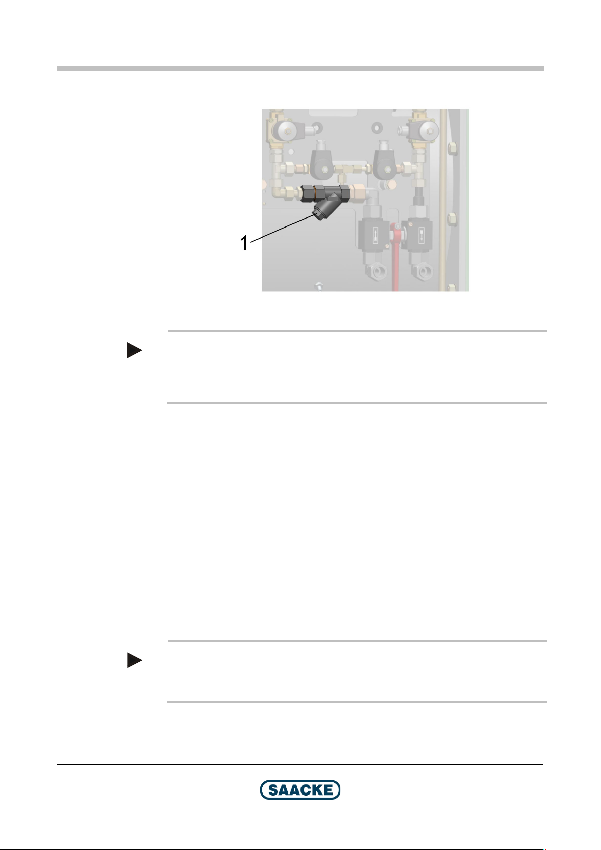
Fig. 16: Position of the ignition transformer (duoblock burner)
Open the control box for the ignition transformer (1).
Check the plug-and-socket connections for external damage.
Check the parts of the ignition cable that are accessible without opening the burner
for external damage.
9.4.8 Checking the Ignition Systems ZAP(ZDAP) and ZA0(ZDA0)
Refer to the manufacturer's documentation on the igniter for the instructions.
44 / 78
Technical Documentation
BA-TEMINOX-GL-Duo2021-02 2021-06-22
Page 45
TEMINOX®
GL
Maintenance / Cleaning
9.5 Maintenance of Components Relevant to the Oil Operation Mode
Manual shut-off fitting supply line / return line
Check 1 year Service personnel Recommendation ---
Dirt trap
Clean 1 year Plant authorities Recommendation Chapter 9.5.1
Oil gun
Check 1 year Service personnel Recommendation ---
Fuel lines outside the burner
Replace the flexible tubes 5 years Service personnel Obligation ---
Rapid shut-off valves
Pressure monitor
Oil flow controller
Replace nozzle plate, vortex plate and
seals of the gun
Replace the oil gun 10 years Service personnel Obligation ---
Check 1 year Plant authorities Recommendation Chapter 9.5.2
5406-A13 / 6027-A10 / 6027-A03 / 6027-B02, Bürkert
Check 1 year Service personnel Recommendation ---
Replace 10 years Service personnel Obligation ---
DWR 40-206, Fema / Honeywell
Check 1 year Service personnel Recommendation ---
Replace 10 years Service personnel Obligation ---
DSF 146 F001, Sauter
Check 1 year Service personnel Recommendation ---
Replace 5 years Service personnel Obligation ---
DWR 6-205, DWR 625-205, Fema / Honeywell
Check 1 year Service personnel Recommendation ---
Replace 10 years Service personnel Obligation ---
Check 1 year Service personnel Recommendation ---
Replace the seal 2 years /
Interval Who? Category Chapter
Interval Who? Category Chapter
Interval Who? Category Chapter
3 years Service personnel Recommendation ---
Interval Who? Category Chapter
Interval Who? Category Chapter
Interval Who? Category Chapter
Interval Who? Category Chapter
12,000
operating hours
Service personnel Recommendation ---
2021-06-22
Technical Documentation
BA-TEMINOX-GL-Duo2021-02 45 / 78
Page 46
Maintenance / Cleaning
TEMINOX®
GL
T102
9.5.1 Cleaning the Dirt Trap
Fig. 17: Dirt trap (example)
Note
Fuel may escape when performing the tasks described below. For this reason,
place an oil drip tray underneath the dirt trap and dispose of any fuel that has
escaped professionally and in an ecologically compatible manner.
Remove the screw (1). Use a size 24 open wrench for this purpose.
Remove the strainer of the dirt trap.
Clean the strainer.
Re-install the strainer.
Tighten the screw (1) again.
9.5.2 Checking the Fuel Lines Outside the Burner
Check the flexible tubes for external damage.
Check whether fuel has escaped in the area around the flexible tubes.
If fuel has escaped:
Immediately switch the burner off.
Find the leak and repair it, if possible.
46 / 78
Note
It might be necessary to replace the flexible tube. In this case, contact the service
personnel.
Dispose of any leakage oil correctly and in an environmentally friendly manner.
Technical Documentation
BA-TEMINOX-GL-Duo2021-02 2021-06-22
Page 47
TEMINOX®
GL
Maintenance / Cleaning
9.6 Maintenance of Components Relevant Especially to the Gas Operation
Gas guns
Check 1 year Service personnel Recommendation ---
Gas control damper(s)
Check 1 year Service personnel Recommendation ---
Interval Who? Category Chapter
Interval Who? Category Chapter
9.7 After Completion of the Maintenance Work
Prepare the burner, the heat generator and the further subsystems of the plant for
operation once you have completed the maintenance work.
Restart the burner.
Transpot
2021-06-22
Technical Documentation
BA-TEMINOX-GL-Duo2021-02 47 / 78
Page 48

Troubleshooting
TEMINOX®
GL
10 Troubleshooting
Note
If problems arise that cannot be solved with the help of the following descriptions,
please contact SAACKE Service.
10.1 Troubleshooting (Gas Operation)
Burner does not start
Possible cause Measures
Control voltage not available
Fuel has not been preselected
Burner still locked by the burner control system after
the safety shut-off
General safety interlock circuit of the plant
interrupted; causes e.g.
– Low water
– Flue gas damper of the heat generator not open
Note
For burner sizes 50 and 70, ignition is direct and electrical in both oil operation and
gas operation. The data related to ignition media and ignition flame therefore does
not apply to these sizes.
Unlock the burner at the burner control system.
Manually driven flue gas damper:
Open flue gas damper.
Flue gas damper driven by the plant control system:
Check the mechanical path of the flue gas damper
If this does not solve the problem, check the
Provide for a supply with control voltage.
Preselect fuel.
Feed in boiler water.
and remove any obstacles.
manufacturer's documentation for solutions or revert
to the service personnel responsible for the heat
generator or try to solve the problem via the plant
control system.
– Emergency stop button of the plant was actuated
– The safety manostat / thermostat of the heat
Boiler control circuit interrupted
48 / 78
generator has triggered a fault and is locked
Technical Documentation
BA-TEMINOX-GL-Duo2021-02 2021-06-22
Ensure that the button was actuated accidentally or
that the reason for the emergency stop has been
eliminated.
Reset the emergency stop button of the plant.
Reset the safety manostat / thermostat. Refer to the
manufacturer's documentation on the heat
generator.
Check the control circuit, if in doubt, revert to the
service personnel.
Page 49

TEMINOX®
GL
Troubleshooting
Burner does not start
Possible cause Measures
Gas safety interlock circuit interrupted, causes e.g.
– Fuel not available or insufficient pressure
Check whether the available gas pressure
corresponds to the plant configuration.
Refer to the manufacturer's documentation on the
fuel supply system.
– Gas pressure monitor in the fuel supply system
incorrectly set or defective
Combustion air fan does not start or triggers a fault during operation
Possible cause Measures
Voltage for drive motor not available
Motor circuit breaker has triggered a fault
Fuse defective
Impeller blocked mechanically
In the case of speed-controlled fans: Incorrect
feedback of the speed pickup
Drive motor defective
Purge phase does not start
Refer to the manufacturer's documentation on the
fuel supply system or revert to the service
personnel.
Provide for a supply with voltage.
Reset the motor circuit breaker.
If the fault persists: Revert to the service personnel.
Replace the fuse.
If the fault persists: Revert to the service personnel.
Revert to the service personnel.
Revert to the service personnel.
Revert to the service personnel.
Possible cause Measures
Flame scanner detects extraneous light
Flame scanner / monitor defective
Leak test of the fuel supply system has triggered a
fault
– Following a safety shut-off, pressure was still
trapped between the rapid shut-off valves in the
fuel supply system
– Manual shut-off valve(s) in the fuel supply system
are not in the correct position
– Rapid shut-off valves in the fuel supply system
leaky or defective
One actuator or multiple actuators does/do not reach
the purge position or incorrect feedback of the speed
pickup (with speed-controlled fans)
Technical Documentation
Revert to the service personnel.
Refer to the manufacturer's documentation on the
Check whether all the manual shut-off valves in the
Revert to the service personnel.
Check furnace.
fuel supply system.
fuel supply system are in the correct position. Refer
to the manufacturer's documentation on the fuel
supply system.
Refer to the manufacturer's documentation on the
fuel supply system.
2021-06-22
BA-TEMINOX-GL-Duo2021-02 49 / 78
Page 50

Troubleshooting
TEMINOX®
GL
Purge phase does not start
Possible cause Measures
Motor circuit breaker (fan) has triggered a fault
Reset the motor circuit breaker.
If the fault persists: Revert to the service personnel.
Safety shut-off during the purge phase
Possible cause Measures
Combustion air pressure monitor has triggered a fault
– Combustion air not available or insufficient
pressure
– Incorrect pressure monitor setting or pressure
monitor defective
General safety interlock circuit of the plant or gas
safety interlock circuit interrupted
Ignition does not start
Possible cause Measures
One actuator or multiple actuators does/do not reach
the ignition position or incorrect feedback of the
speed pickup
No ignition flame
Possible cause Measures
No ignition spark
Check whether the available pressure corresponds
to the plant configuration.
Revert to the service personnel.
Refer to "Burner does not start".
Revert to the service personnel.
– Ignition transformer does not deliver secondary
voltage
Check whether the ignition transformer is supplied
with voltage.
Check connections and cables.
If defective: Revert to the service personnel.
– Ignition electrodes soiled or defective
Ignition medium not available or
insufficient/excessive pressure
Revert to the service personnel.
Check whether the available pressure corresponds
to the plant configuration.
Check whether all the manual shut-off valves in the
ignition gas supply system are in the correct
position.
Check the pressure reducing valve (if installed).
Rapid shut-off valves for ignition medium do not open
Problems with the ignition
Possible cause Measures
Flame scanner does not detect ignition flame
Revert to the service personnel.
Clean the flame scanner (refer to the chapter
entitled "Maintenance/Cleaning").
If this measure does not eliminate the fault: Revert
to the service personnel.
50 / 78
Technical Documentation
BA-TEMINOX-GL-Duo2021-02 2021-06-22
Page 51
TEMINOX®
GL
Troubleshooting
Problems with the ignition
Possible cause Measures
Ignition flame instable
No main flame
Possible cause Measures
Main fuel not available or insufficient/excessive
pressure
Revert to the service personnel.
Check whether the available pressure corresponds
to the plant configuration.
Check whether all the manual shut-off valves in the
fuel supply system are in the correct position. Refer
to the manufacturer's documentation on the fuel
supply system.
Rapid shut-off valves in the fuel supply system do not
open
Refer to the manufacturer's documentation on the
fuel supply system.
If in doubt: Revert to the service personnel.
Air in the fuel line
Unsatisfactory combustion or fault in controlled operation
Possible cause Measures
Another subsystem of the plant (e.g. control cabinet,
heat generator) has triggered a fault / caused a
safety shut-off
De-aerate fuel line. Refer to the manufacturer's
documentation on the fuel supply system.
Refer to the manufacturer's documentation on the
faulty subsystem or revert to the service personnel.
One actuator or multiple actuators does/do not reach
the intended position or incorrect feedback of the
speed pickup
Flame detection system triggers a fault
General safety interlock circuit interrupted
Gas safety interlock circuit interrupted
Burner emits soot, unsatisfactory burnout or any
other undesired operating mode of the burner not
described in any other context
Revert to the service personnel.
Clean the flame scanner (refer to the chapter
entitled "Maintenance/Cleaning").
Ensure sufficient cooling.
If this measure does not eliminate the fault: Revert
to the service personnel.
Refer to "Burner does not start"
Refer to "Burner does not start"
Revert to the service personnel.
2021-06-22
Technical Documentation
BA-TEMINOX-GL-Duo2021-02 51 / 78
Page 52

Troubleshooting
TEMINOX®
GL
10.2 Troubleshooting (Oil Operation)
Burner does not start
Possible cause Measures
Control voltage not available
Fuel has not been preselected
Burner still locked by the burner control system after
the safety shut-off
General safety interlock circuit of the plant
interrupted; causes e.g.
– Low water
– Flue gas damper of the heat generator not open
– Emergency stop button of the plant was actuated
Provide for a supply with control voltage.
Preselect fuel.
Unlock the burner at the burner control system.
Feed in boiler water.
Manually driven flue gas damper:
Open flue gas damper.
Flue gas damper driven by the plant control system:
Check the mechanical path of the flue gas damper
and remove any obstacles.
If this does not solve the problem, check the
manufacturer's documentation for solutions or revert
to the service personnel responsible for the heat
generator or try to solve the problem via the plant
control system.
Make sure that the button was actuated accidentally
or that the reason for the emergency stop has been
eliminated.
Reset the emergency stop button of the plant.
– The safety manostat / thermostat of the heat
generator has triggered a fault and is locked
Boiler control circuit interrupted
Combustion air fan does not start or triggers a fault during operation
Possible cause Measures
Voltage for drive motor not available
Motor circuit breaker has triggered a fault
Reset the safety manostat / thermostat. Refer to the
manufacturer's documentation on the heat
generator.
Check the control circuit, if in doubt, revert to the
service personnel.
Provide for a supply with voltage.
Reset the motor circuit breaker.
If the fault persists: Revert to the service personnel.
Fuse defective
Replace the fuse.
If the fault persists: Revert to the service personnel.
Impeller blocked mechanically
In the case of speed-controlled fans: Incorrect
feedback of the speed pickup
Drive motor defective
Technical Documentation
Revert to the service personnel.
Revert to the service personnel.
Revert to the service personnel.
52 / 78
BA-TEMINOX-GL-Duo2021-02 2021-06-22
Page 53

TEMINOX®
GL
Troubleshooting
Purge phase does not start
Possible cause Measures
Pressure monitor (L) for protection against dry
running in the fuel supply system triggers a fault
– Fuel not available on the upstream side of the
booster pump or insufficient fuel pressure
Check whether the available oil pressure
corresponds to the plant configuration.
Refer to the manufacturer's documentation on the
fuel supply system.
Flame scanner detects extraneous light
Flame scanner / monitor defective
One actuator or multiple actuators does/do not reach
the purge position or incorrect feedback of the speed
pickup (with speed-controlled fans)
Motor circuit breaker (fan) has triggered a fault
Check furnace.
Revert to the service personnel.
Revert to the service personnel.
Reset the motor circuit breaker.
If the fault persists: Revert to the service personnel.
Safety shut-off during the purge phase
Possible cause Measures
Combustion air pressure monitor has triggered a fault
– Combustion air not available or insufficient
pressure
– Incorrect pressure monitor setting or pressure
monitor defective
General safety interlock circuit of the plant interrupted
Oil safety interlock circuit interrupted, causes e.g.
Check whether the available pressure corresponds
to the plant configuration.
Revert to the service personnel.
Refer to "Burner does not start".
– Fuel not available or insufficient pressure
Check whether the available fuel pressure
Refer to the manufacturer's documentation on the
– Incorrect setting of oil pressure monitor (L) or (H)
Ignition does not start
Possible cause Measures
One actuator or multiple actuators does/do not reach
the ignition position or incorrect feedback of the
speed pickup
No ignition spark
Possible cause Measures
Ignition transformer does not deliver secondary
voltage
Revert to the service personnel.
Check whether the ignition transformer is supplied
Check connections and cables.
If defective: Revert to the service personnel.
Technical Documentation
corresponds to the plant configuration.
fuel supply system.
Revert to the service personnel.
with voltage
2021-06-22
BA-TEMINOX-GL-Duo2021-02 53 / 78
Page 54

Troubleshooting
TEMINOX®
GL
No ignition spark
Possible cause Measures
Ignition electrodes soiled or defective
No main flame
Possible cause Measures
Main fuel not available or insufficient/excessive
pressure
Revert to the service personnel.
Check whether the available pressure corresponds
to the plant configuration.
Check the oil pressure in the closed circular pipeline
(fuel supply system).
Check the booster pump in the fuel supply system.
Refer to the manufacturer's documentation on the
fuel supply system.
Check whether all the manual shut-off valves in the
fuel supply system are in the correct position. Refer
to the manufacturer's documentation on the fuel
supply system.
Rapid shut-off valves do not open
Air in the fuel line
Incorrect setting of oil pressure monitor or oil
pressure monitor defective
Unsatisfactory combustion or fault in controlled operation
Revert to the service personnel.
De-aerate fuel line. Refer to the manufacturer's
documentation on the fuel supply system.
Revert to the service personnel.
Possible cause Measures
Another subsystem of the plant (e.g. control cabinet,
heat generator) has triggered a fault / caused a
safety shut-off
One actuator or multiple actuators does/do not reach
the intended position or incorrect feedback of the
speed pickup
Flame detection system triggers a fault
Refer to the manufacturer's documentation on the
faulty subsystem or revert to the service personnel.
Revert to the service personnel.
Clean the flame scanner (refer to the chapter
entitled "Maintenance/Cleaning").
Ensure sufficient cooling.
If this does not solve the problem: revert to the
service personnel.
Nozzle system dirty
General safety interlock circuit interrupted
Oil safety interlock circuit interrupted
Burner emits soot, unsatisfactory burnout or any
other undesired operating mode of the burner not
described in any other context
Revert to the service personnel.
Refer to "Burner does not start"
Refer to "Safety Shut-Off During the Purge Phase
Revert to the service personnel.
54 / 78
Technical Documentation
BA-TEMINOX-GL-Duo2021-02 2021-06-22
Page 55

TEMINOX®
GL Dimensions / Types
TMX255
11 Dimensions / Types
Note
Plant-specific dimensional differences are possible. For this reason, the
dimensions specified here are intended for planning purposes only.
11.1 Arrangement of the Ignition Medium and Fuel Fittings
Fig. 18: Arrangement of the ignition and fuel fittings
A Arrangement “left”
B Arrangement “right”
The arrangement depends on the air inlet position:
Air inlet position Arrangement of the ignition and fuel fittings
0° Either left or right
45°, 90° Left
180° Either left or right
270°, 315° Right
Technical Documentation
2021-06-22
BA-TEMINOX-GL-Duo2021-02 55 / 78
Page 56

Dimensions / Types
TEMINOX®
GL
TMX181
Arrangement and Designation of the Main Fuel Oil / Ignition Medium Connections,
Burner Sizes up to 140
56 / 78
Fig. 19: Example: arrangement “right”
1 Main fuel oil inlet (supply line), designated by arrow in direction of flow
2 Main fuel oil outlet (return line), designated by arrow in direction of flow
4 Ignition medium inlet
Technical Documentation
BA-TEMINOX-GL-Duo2021-02 2021-06-22
Page 57
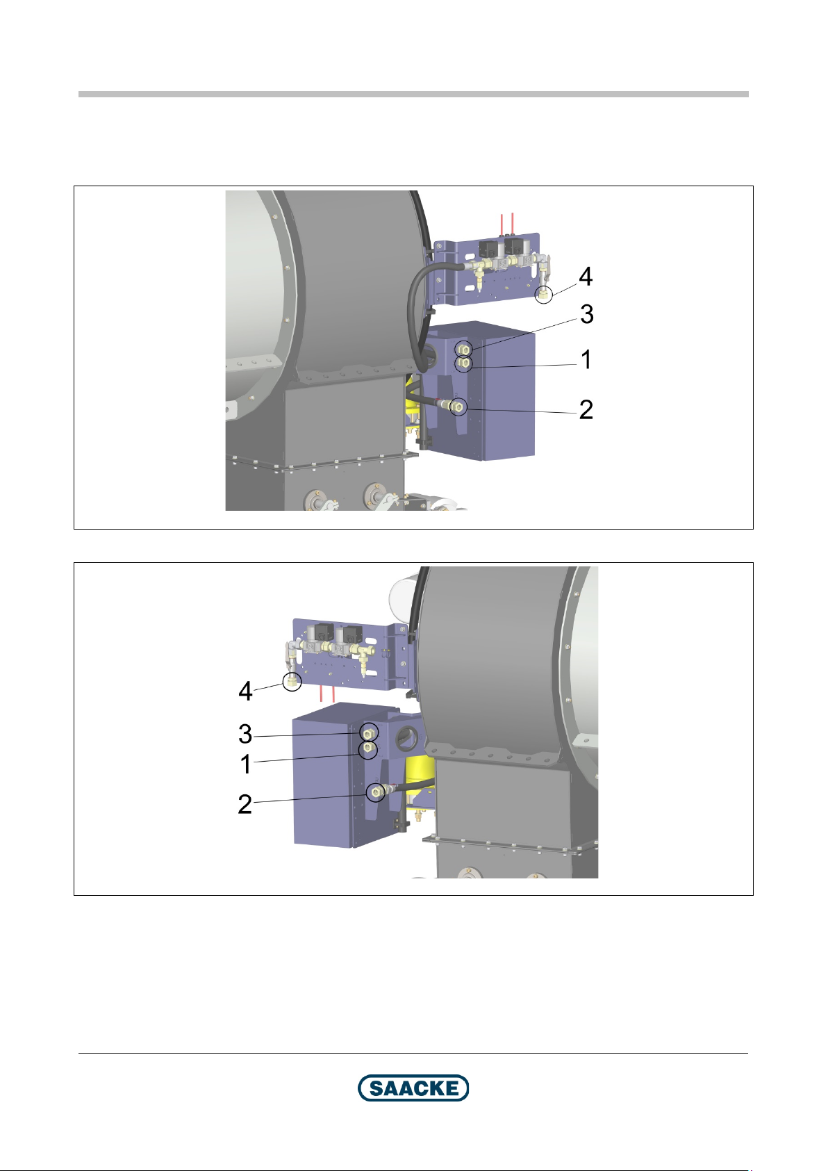
TEMINOX®
GL Dimensions / Types
TMX195
TMX196
Arrangement and Designation of the Main Fuel Oil / Ignition Medium Connections,
Burner Sizes 200 and higher
Fig. 20: Arrangement “left”
Fig. 21: Arrangement “right”
2021-06-22
1 Main fuel oil inlet (supply line), designation “S”
2 Main fuel oil outlet (return line), designation “R”
3 Control line, designation “C”
4 Ignition medium inlet
Technical Documentation
BA-TEMINOX-GL-Duo2021-02 57 / 78
Page 58
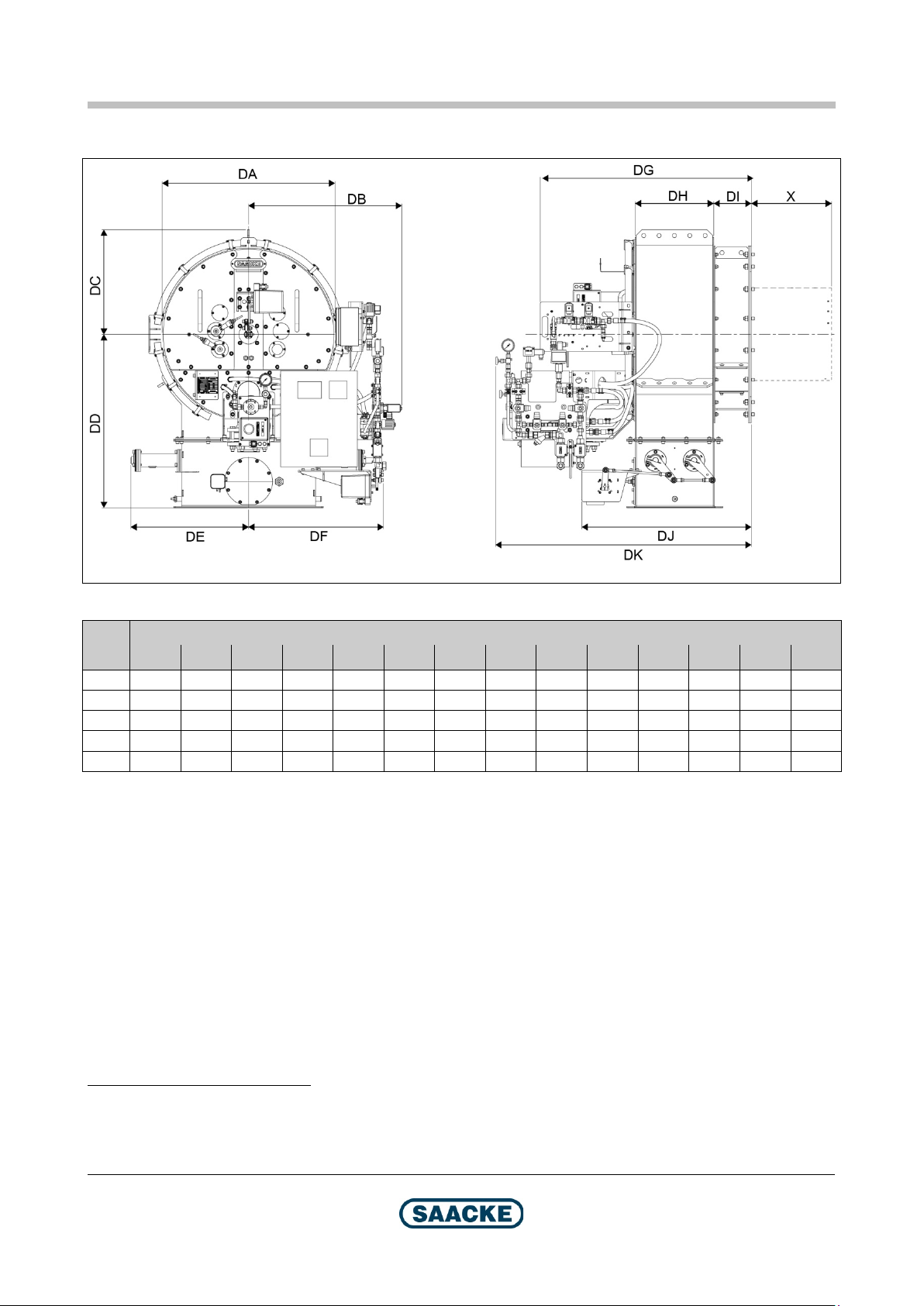
Dimensions / Types
TEMINOX®
GL
TMX182
DE
cold16
DE
warm17
DF
cold20
DF
warm
X
(max.)
11.2 Basic Dimensions
Fig. 22: Basic dimensions
Burner
size
70 720 775 440 825 310 520 370 610 830 290 200 765 1240 485
100 820 780 490 885 335 565 420 660 1140 350 200 825 1300 505
140 945 780 550 900 385 615 470 705 1205 410 200 890 1430 520
200 1090 780 625 1080 445 675 530 770 1525 460 435 1175 1660 545
280 1300 830 725 1175 545 780 650 870 1675 610 435 1450 1815 570
DA DB DC DD
Dimensions in mm
17
DG DH DI DJ DK
16
Combustion air temperature <60 °C
17
Combustion air temperature >60 °C
58 / 78
Technical Documentation
BA-TEMINOX-GL-Duo2021-02 2021-06-22
Page 59

TEMINOX®
GL Dimensions / Types
11.3 Weight
11.3.1 Mixing System
Burner size
70 350 / 385
100 420 / 460
140 510 / 550
200 710 / 810
280 890 / 940
11.3.2 Integrated Burner Control System (Optional)
Approx. 21 kg
11.3.3 Motor Control (Optional)
Approx. 27 kg
With controlled primary gas / without controlled primary gas
Weight (approximate values) [kg]
2021-06-22
Technical Documentation
BA-TEMINOX-GL-Duo2021-02 59 / 78
Page 60
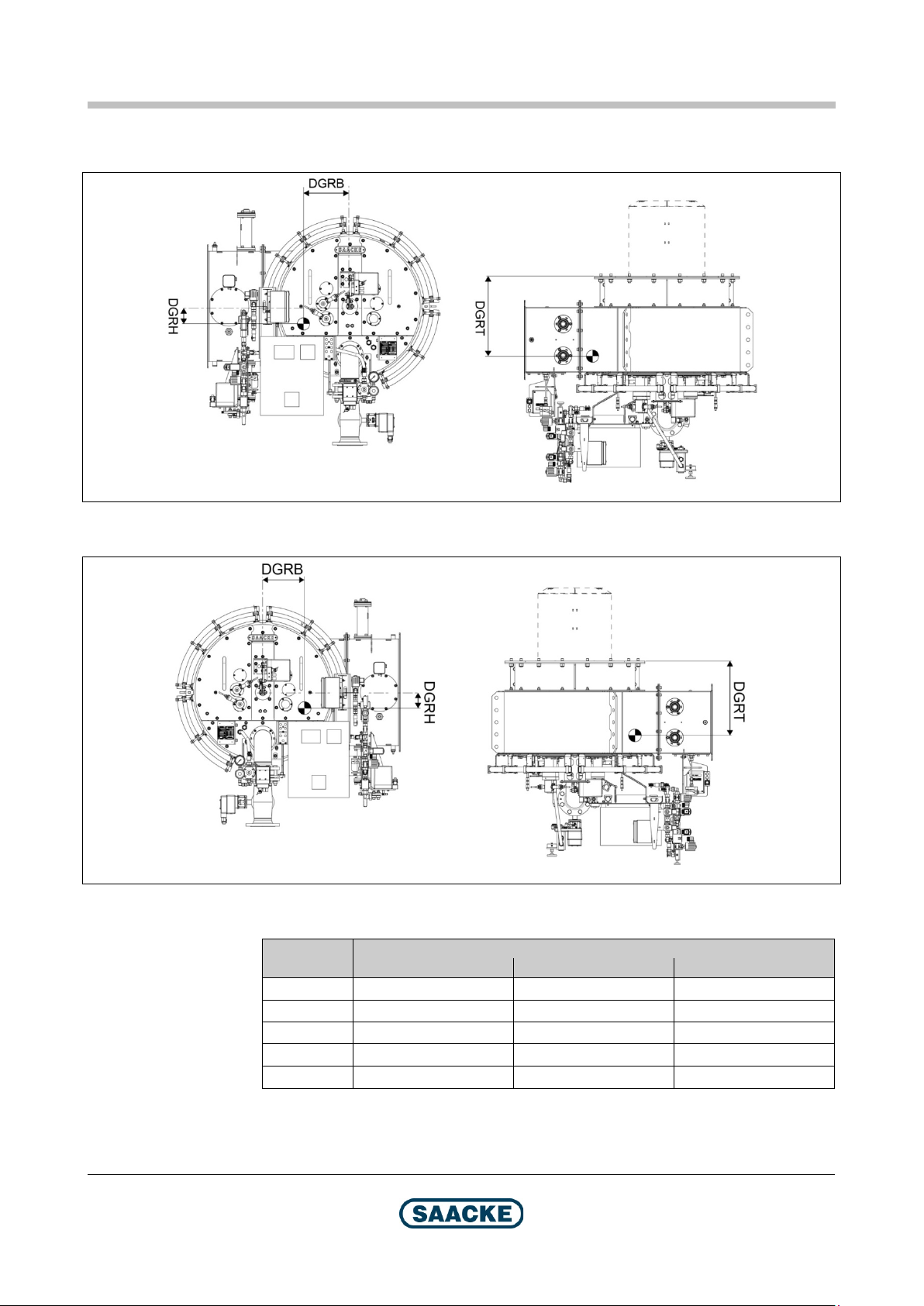
Dimensions / Types
TEMINOX®
GL
TMX183
TMX184
Dimensions in mm
11.4 Center of Gravity
Fig. 23: Center of gravity, arrangement „left“, valid for air intake positions:
0° (arr. “left”), 45°, 90° and 180° (arr. “left”)
60 / 78
Fig. 24: Center of gravity, arrangement „right“, valid for air intake positions:
Burner size
180° (arr. “right”), 270°, 315° and 0° (arr. “right”)
DGRB DGRH DGRT
70 10 110 425
100 30 110 440
140 65 95 460
200 120 70 600
280 180 80 670
Technical Documentation
BA-TEMINOX-GL-Duo2021-02 2021-06-22
Page 61

TEMINOX®
GL Dimensions / Types
TMX185
DGH
primary gas
DGH
primary gas
11.5 Position of the Fuel Inlets
Fig. 25: Position of the fuel connections – gas
Dimensions in mm
Burner size
70 440 720 750
100 485 760 810
140 560 880 910
200 650 1010 1240
280 700 1065 1390
without controlled
with controlled
DGT
2021-06-22
Technical Documentation
BA-TEMINOX-GL-Duo2021-02 61 / 78
Page 62

Dimensions / Types
TEMINOX®
GL
TMX186
Dimensions in mm for arrangement “right“
Dimensions in mm for arrangement “left“
Fig. 26: Position of the fuel connections – oil, burner sizes up to 140, example:
arrangement “right”
Burner size
70 675 615 900 800
100 675 630 960 860
140 705 655 1130 1030
Burner size
70 675 615 1040 1140
100 675 630 1100 1200
140 705 655 1170 1270
DOB DOH DOT1 (Inlet) DOT2 (Outlet)
DOB DOH DOT1 (Inlet) DOT2 (Outlet)
62 / 78
Technical Documentation
BA-TEMINOX-GL-Duo2021-02 2021-06-22
Page 63
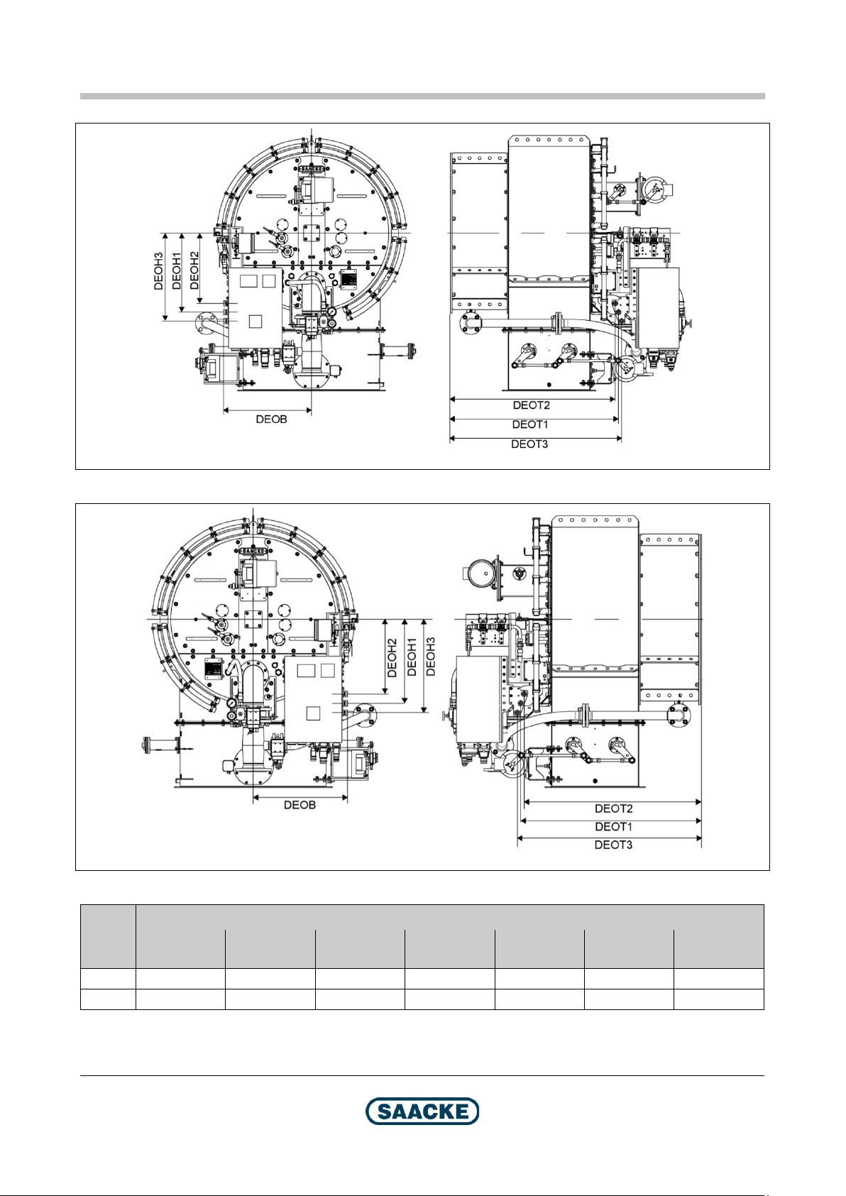
TEMINOX®
GL Dimensions / Types
TMX252
TMX253
Fig. 27: Pos. of the fuel connections – oil, burner sizes 200 and higher, arr. “left”
Fig. 28: Pos. of the fuel connections – oil, burner sizes 200 and higher, arr. “right”
Burner
size
200 660 530 465 600 1110 1085 1130
280 660 590 525 655 1255 1280 1235
DEOB
DEOH1
(Inlet)
DEOH 2
(Control line)
Dimensions in mm
DEOH 3
(Outlet)
DEOT1
(Inlet)
DEOT2
(Control line)
Technical Documentation
2021-06-22
BA-TEMINOX-GL-Duo2021-02 63 / 78
DEOT3
(Outlet)
Page 64

Dimensions / Types
TEMINOX®
GL
TMX189
Dimensions in mm
Fig. 29: Position of the fuel connections – Ignition medium
Burner
size
7018 --- --- ---
100 575 165 1090
140 590 190 1155
200 650 165 1480
280 650 220 1620
Note
DZB DZH DZT
The figure shows the arrangement “right” for the ignition medium and fuel fittings.
For the arrangement “left”, the dimensions are identical.
18
No ignition medium (direct electrical ignition)
64 / 78
Technical Documentation
BA-TEMINOX-GL-Duo2021-02 2021-06-22
Page 65

TEMINOX®
GL Dimensions / Types
TMX190
Dimensions in mm
DLT
DLH
11.6 Position of the Air Inlet Connection
Fig. 30: Air inlet position
Burner size
70 340 825
100 370 885
140 405 900
200 665 1080
280 740 1175
2021-06-22
Technical Documentation
BA-TEMINOX-GL-Duo2021-02 65 / 78
Page 66

Dimensions / Types
TEMINOX®
GL
TMX143
Dimensions in mm
DBP1
DBP2
DBP319 (min.)
11.7 Burner Mounting Plate
Fig. 31: Burner mounting plate
Burner size
70 355 650 720
100 420 750 820
140 495 850 920
200 595 1000 1090
280 700 1100 1190
19
Outer diamater of burner mounting plate
66 / 78
Technical Documentation
BA-TEMINOX-GL-Duo2021-02 2021-06-22
Page 67

TEMINOX®
GL Dimensions / Types
T157a
1
2
3
4
5
6
Fig. 32: Detail: Mounting the burner on the heat generator
1 Hexagonal nut
2 Washer
3 Stud screw
4 Flange (burner)
5 Gasket (fibre plate)
6 Burner mounting plate
2021-06-22
Technical Documentation
BA-TEMINOX-GL-Duo2021-02 67 / 78
Page 68

Dimensions / Types
TEMINOX®
GL
TMX191
11.8 Minimum Distances
Note
The dimensions stated here describe the optimum dimensions with regard to
ergonomics and process engineering. If, at your plant, it is impossible to meet the
requirements, please contact Business Unit SIS at the head office in Bremen,
Germany.
Note
The areas marked in gray in the following figures must be kept free of any
stationary obstacles (for example, pipelines or walls).
11.8.1 All Duoblock Burners
68 / 78
Fig. 33: Minimum distances (all duoblock burners)
Technical Documentation
BA-TEMINOX-GL-Duo2021-02 2021-06-22
Page 69

TEMINOX®
GL Dimensions / Types
TMX197
11.8.2 “Outer” Ignition and Fuel Fittings
Fig. 34: Minimum distances “outer” ignition and fuel fittings
Burner size
70 900 1100
100 970 1180
140 1090 1280
200 1300 1450
280 1400 1610
20
Combustion air temperature <60 °C
21
Combustion air temperature >60 °C
Dimensions in mm
DDIS1
Cold20 Warm21
Technical Documentation
2021-06-22
BA-TEMINOX-GL-Duo2021-02 69 / 78
Page 70

Dimensions / Types
TEMINOX®
GL
TMX198
Dimensions in mm
11.8.3 “Inner” Ignition and Fuel Fittings
Fig. 35: Minimum distances “inner” ignition and fuel fittings
Burner size
TEMINOX G TEMINOX GL
70 1230 1650
100 1450 1790
140 1580 1870
200 1730 1730
280 1850 1850
DDIS1
70 / 78
Technical Documentation
BA-TEMINOX-GL-Duo2021-02 2021-06-22
Page 71
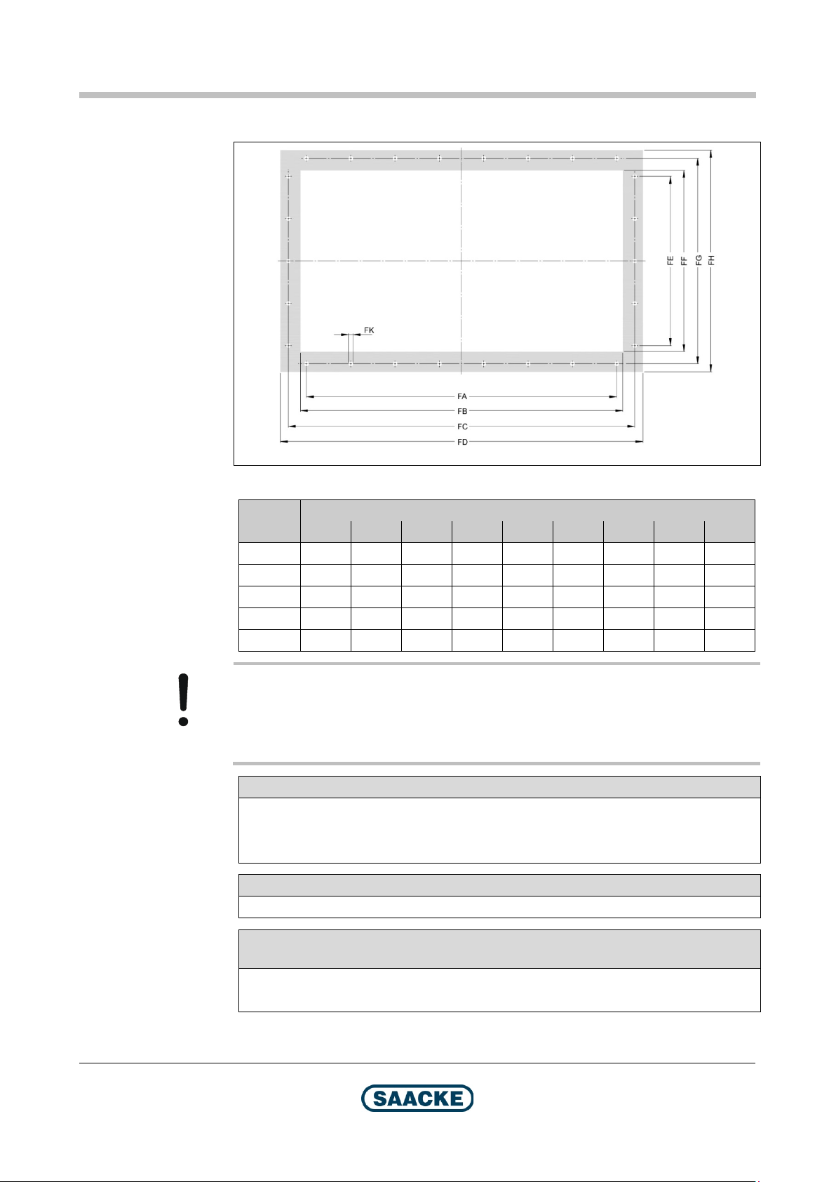
TEMINOX®
GL Dimensions / Types
U034
11.9 Connection Dimensions
Fig. 36: Connection dimensions for expansion joint / air duct
Burner
size
70 4 x 120 480 540 580 2 x 120 280 340 380 12
100 4 x 150 580 640 680 2 x 110 340 400 440 12
140 5 x 140 680 740 780 3 x 120 400 460 500 12
200 6 x 130 800 860 900 3 x 130 450 510 550 12
280 7 x 140 1000 1060 1100 5 x 115 600 660 700 12
Dimensions in mm
FA FB FC FD FE FF FG FH FK
Caution!
An expansion joint must be installed between the (external) fan and the
combustion air inlet into the burner. The expansion joint is not included in the
burner product package.
Main fuel inlet for gas
Burner sizes ≤ 100: Welding neck flange for tube DN 80
Burner size 140: Welding neck flange for tube DN100
Burner sizes ≥ 200: Welding neck flange for tube DN125
Main fuel oil inlet and outlet
Compression-tube fittings for 22 mm tube
Ignition medium inlet
(burners for gas operation with burner sizes 100 or higher)
Burner size 100 / 140: Compression-tube fitting for 15 mm tube
Burner size 200 / 280: Compression-tube fitting for 22 mm tube
Technical Documentation
2021-06-22
BA-TEMINOX-GL-Duo2021-02 71 / 78
Page 72

Dimensions / Types
TEMINOX®
GL
11.10 Tightening Torque for Mounting Screws
Note
The tightening torques stated in this chapter are approximate values. They are
valid for new, galvanized or chromated screws (strength category 8.8) and nuts
(strength category 8). It is assumed that all component surfaces are clean. The
total coefficient of friction is µ = 0.12 (e.g. lightly oiled).
Burner size Size of screw / stud Size of nut Tightening torque
All M16 M16 194 Nm
72 / 78
Technical Documentation
BA-TEMINOX-GL-Duo2021-02 2021-06-22
Page 73
TEMINOX®
GL
Technical Data
12 Technical Data
Note
These data specified in this context apply to the following ambient conditions:
Air density 1.15 kg/m³
Installation height 250 m above sea level
Air temperature between 10 °C and 30 °C
In the case of deviating ambient conditions, please contact SAACKE Bremen.
Note
If the outline data applicable to your system are not covered by the technical data
listed here, please contact Business Unit SIS at the head office in Bremen,
Germany.
12.1 Capacity and Turndown Ratio
Note
The minimum and maximum capacity of your burner is specified on the rating plate
of the burner.
2021-06-22
Technical Documentation
BA-TEMINOX-GL-Duo2021-02 73 / 78
Page 74

Technical Data
TEMINOX®
GL
12.2 Requirements for Fuels and Further Media
Caution!
The ambient temperature of the burner must not exceed 40 °C and must not drop
below 5 °C. Otherwise the function of the electrical control and monitoring
components in the burner cannot be guaranteed.
Caution!
The maximum temperature for the flame scanner is 60 °C. Provide cooling air for
the flame scanner if this temperature could be exceeded during operation (for
example due to preheated combustion air for duoblock burners) or when stopped
(due to radiant heat from the boiler).
Main fuel light oil
Type Fuel oil EL according to DIN 51603-1
Kinematic viscosity at the burner inlet ≤6 mm²/s
Temperature at burner inlet Minimum 10 °C
Maximum 40 °C
Pressure at burner inlet Minimum 28 bar
Maximum 30 bar
Pressure at burner outlet Maximum 1 bar
Main fuel gas
Type Gases of the second family,
groups H and L according to EN 437
On request:
Liquefied petroleum gas
Biogas
Special gases
Pressure at burner inlet Plant-specific
The pressures adjusted during
commissioning must be kept.
Temperature at burner inlet Minimum 5 °C
Maximum 50 °C
Status Gas phase, i.e. liquefied gas must have
Ignition medium
For gas operation with burner sizes 100 and higher
Type Gases of the second family,
Pressure upstream of ignition fittings Minimum 250 mbar
evaporated on the upstream side of the
burner
groups H and L according to DIN EN 437
Maximum 500 mbar
The pressures adjusted during
commissioning must be kept.
74 / 78
Technical Documentation
BA-TEMINOX-GL-Duo2021-02 2021-06-22
Page 75

TEMINOX®
GL
Technical Data
Combustion air
Temperature at burner inlet with monoblock burners Minimum 5 °C22
Maximum 55 °C
Temperature at burner inlet with duoblock burners Minimum 5 °C22
Maximum 150 °C (TEMINOX G)
Maximum 90 °C (TEMINOX L and GL)
Relative humidity Maximum 80 %
“Mini-Rezi“ (optional)
Flue gas temperature at burner inlet (monoblock burners) Maximum 450 °C
Based on special agreements, solutions
for flue gas temperatures up to 550 °C are
possible. Please have in mind that these
individual solutions are not shown in this
document and that they can differ in detail
from the figures shown in this document.
Temperature of the flue gas and fresh air mixture at the
fan inlet (monoblock burner)
Temperature of the flue gas and fresh air mixture at the
Minimum 5°C
Maximum 55°C
See table “Combustion Air”
burner inlet (duoblock burner)
FGR proportion (monoblock burners)24 Maximum of 5% for variant “butterfly
damper with servomotor” or “manually
adjustable butterfly damper”
Maximum of 7% for variant “control
damper with servomotor”
FGR proportion (duoblock burners)24 Maximum of 5% for uncontrolled flue gas
actuator
Maximum of 7% for controlled flue gas
actuator
22
22,23
22,23
12.3 Distances of Fuel Supply System Components
Distance between rapid shut-off valve 2 for main fuel gas and main fuel gas inlet (pipe length)
Burner sizes 50-70 Max. 0.5 m
Burner sizes 100-280 Max. 1.5 m
12.4 Electrical Data
Protection class IP 44 according to EN 60529
Control voltage 1 ~ 230 V
50 Hz
Monoblock burner fan motor 380 – 420 V
Maximum 50 Hz (also applies to operation with
frequency converter)
22
The specified temperature range must be maintained at all times (even during standstill).
23
55 °C or above: Special variant for preheated combustion air
24
The maximum FGR proportion valid for your plant must be designed plant specifically. Please contact the
business unit SIS at the corporate head office in Bremen if a higher FGR proportion is required.
Technical Documentation
2021-06-22
BA-TEMINOX-GL-Duo2021-02 75 / 78
Page 76

Technical Data
TEMINOX®
GL
TMX200
TMX199
12.5 Permitted Mounting Positions
The burner may be installed in a horizontal position only.
Monoblock Burners
Fig. 37: Mounting position monoblock burners
It must not be used as an inverted or a floor burner.
1 Servomotor for air control dampers
Line A (center line of servomotor) must be parallel to line B (floor).
The servomotor for air control dampers must be located on the upper side.
Duoblock Burners
Fig. 38: Mounting position duoblock burners
1 Connection plate (here: yellow)
Line A (top of connection plate) must be parallel to line B (floor).
The arc of the connection plate must be below line A.
Air inlet positions see chapter “Possible Air and Fuel Inlet Positions“.
Technical Documentation
76 / 78
BA-TEMINOX-GL-Duo2021-02 2021-06-22
Page 77

TEMINOX®
GL
Technical Data
12.6 Acoustic Emissions
The acoustic emissions depend on the plant configuration. Please contact
Business Unit SIS at the head office in Bremen, Germany.
2021-06-22
Technical Documentation
BA-TEMINOX-GL-Duo2021-02 77 / 78
Page 78

For local contacts please see www.saacke.com
SAACKE GmbH
Suedweststrasse 13
28237 Bremen
Germany
Tel.: +49 421 6495-0
Fax: +49 421 6495-5224
info@saacke.com
www.saacke.com
SAACKE Service:
Industrial Solutions
Supportline: +800-10020001
or +49 421 6495-5201
spares-industrial@saacke.com
service-industrial@saacke.com
Marine Systems
Hotline Germany: +49 421 6495-5229
Hotline Worldwide: +1 954 767 0309
spares-marine@saacke.com
service-marine@saacke.com
 Loading...