

FLUS 06 UV / FLS 09 UV
Operating Instructions
Flame Detection System
2014-03-05
1-8254-8054b-02
Combustion and Energy Systems

The reproduction, distribution and utilization of this
document as well as the communication of its contents
to others without express authorization is prohibited.
Offenders will be held liable for the payment of
f the grant of
Copyright reserved
Technical Documentation SAACKE
Original Manual
damages. All rights reserved in the event o
a patent, utility model or design.

Technology with a Future
rate engineering and continuous
research and development, ensure
Power of innovation, technical
perfection and reliability of all products
account for SAACKE’s technological
ship. Competent project
management, comprehensive
operational advice, and a worldwide
service network stand for customer
proximity and partnership with a
guaranteed future within the industrial
SAACKE worldwide -
For more than 80 years SAACKE has set
standards in economic, eco-friendly and
easy-to-service burner technology.
Firstoptimization of products and systems,
supported by extensive in-house
requirements and sustain flex ibility.
leader
thermal market.
Combustion and Energy Systems

Contents
FLUS 06 UV / FLS 09 UV
0 Contents
0 Contents ............................................................................................................................... 4
1 About this Document ........................................................................................................... 5
2 Safety .................................................................................................................................... 6
2.1 Documentation is a part of the product! .............................................................................................. 6
2.2 Symbols ............................................................................................................................................... 6
2.3 Safety in General ................................................................................................................................. 7
2.4 Intended Use ....................................................................................................................................... 7
2.5 Limitation of Liability ............................................................................................................................ 7
2.6 Qualified Staff ...................................................................................................................................... 7
2.7 Electrical Hazards ............................................................................................................................... 8
2.8 Dangers from Ambient Conditions ...................................................................................................... 8
3 Transport, Storage and Packing ......................................................................................... 9
3.1 Checking the Delivery ......................................................................................................................... 9
3.2 Reporting Transport Damage .............................................................................................................. 9
3.3 Instructions for Storage ....................................................................................................................... 9
3.4 Disposal of the Packaging ................................................................................................................... 9
3.5 Disposal of the Product ....................................................................................................................... 9
4 Scope of Delivery ............................................................................................................... 10
5 Design and Function ......................................................................................................... 11
5.1 Flame Scanner FLS 09 UV ............................................................................................................... 11
5.2 Flame Monitor FLUS 06 UV .............................................................................................................. 12
6 Installation .......................................................................................................................... 15
7 Maintenance ....................................................................................................................... 16
7.1 Cleaning the FLS 09 UV Flame Scanner / Running the Shut-off Check .......................................... 16
7.2 Flame Monitor FLUS 06 UV .............................................................................................................. 18
8 Troubleshooting ................................................................................................................ 19
9 Repair ................................................................................................................................. 20
10 Technical Data ................................................................................................................... 21
10.1 Flame Scanner FLS 09 UV ............................................................................................................... 21
10.2 Flame Monitor FLUS 06 UV .............................................................................................................. 23
4 / 26
Technical Documentation
1-8254-8054b-02 2014-03-05

FLUS 06 UV / FLS 09 UV
About this Document
1 About this Document
This document describes the SAACKE flame detection system FLUS 06 UV /
FLS 09 UV. It provides detailed information on function, installation and
maintenance of the flame detection system.
Please read this document and the safety instructions it contains carefully before
working with the flame detection system.
The initial commissioning of the flame detection system may be performed during
commissioning of the burner by personnel specially trained for this purpose only.
Further information on initial commissioning can therefore be found in the separate
service manual for the flame detection system and in the commissioning
instructions for your burner.
2014-03-05
Technical Documentation
1-8254-8054b-02 5 / 26
Safety
FLUS 06 UV / FLS 09 UV
2 Safety
2.1 Documentation is a part of the product!
This document is an integral part of the product. It must be retained for the entire
service life of the product. Make this document available to the staff responsible for
the work described in it. Add any updates you receive later from SAACKE to the
document.
Help us improve this documentation!
We appreciate any feedback that improves the quality of our documentation. You
will find our address on the back of this document.
2.2 Symbols
Especially important information in this docum ent is hi ghligh ted b y the
corresponding symbols:
Warning!
The industrial safety symbol identifies safety instructions whose purpose is to
prevent physical injury or death. Follow these safety instructions carefully and be
especially cautious during the work/procedures they refer to.
Warning! Risk of death from electric shock!
The electricity symbol identifies safety instructions whose purpose is to prevent
physical injury or death from electric shock. Follow these safety instructions
carefully and be especially cautious during the work/procedures they refer to.
Caution!
The caution symbol identifies all safety warnings whose purpose is to prevent
damage or destruction of the product and/or other plant components.
6 / 26
Note
This points to information or notes that are especially useful.
Technical Documentation
1-8254-8054b-02 2014-03-05
FLUS 06 UV / FLS 09 UV
2.3 Safety in General
The "Safety" chapter gives you an overview of the safety aspects you must pay
attention to in order to work with the product safely. Any individual who assembles,
installs, mounts, commissions, operates and/or does maintenance on the product
described must read and follow the instructions in this chapter carefully to avoid
physical injury and material damage. Your saf et y is at stak e.
In addition to these general safety instructions you will find specific safety
instructions in the product documentation related to individual actions or
procedures.
Only if you follow all of the safety instructions will you be able to provide the best
possible protection for yourself, your colleagues and the environment by ensuring
that the product functions safely and reliably.
In addition to this, it is imperative that you comply with the accident prevention and
safety regulations of the country you are working in.
2.4 Intended Use
The product supplied must only be used in a coherent plant configuration. A plant
configuration is coherent if the product supplied is the equivalent of the plant
component it replaces or it is used according to the manufacturer's specifications.
You can verify this by checking the technical data given in this document.
Safety
2.5 Limitation of Liability
SAACKE shall not be held liable for damage resulting from any use of the product
other than its intended one, from ignoring the documentation or from operation by
inadequately qualified staff. The risk in this case lies with the operator / plant
authorities alone.
2.6 Qualified Staff
Warning!
Risk of physical injury and damage from incorrect operation!
The plant authorities must ensure that only qualified and authorized staff works
with the product.
Qualified staff in the context of this documentation are individ uals w ho ha ve the
training that enables them to handle the product described and are authorized by
the plant authorities to assemble, install, mount, commission, operate and/or do
maintenance on the product.
2014-03-05
Technical Documentation
1-8254-8054b-02 7 / 26
Safety
FLUS 06 UV / FLS 09 UV
2.7 Electrical Hazards
Warning! Risk of death from electric shock!
Damaged lagging or live components that are not covered correctly present a risk
of death from electric shock!
Warning! Risk of death from electric shock!
Carelessness can lead to an electric shock.
This is why when you work with electrical equipment, you must always first:
1. Disconnect each piece of equipment from the mains.
2. Secure it to prevent it from being switched back on.
3. Check that the equipment is de-energized.
4. Ground the equipment and short-circuit it.
5. Cover other components/equipment nearby that are energized.
6 Secure the danger zone, for example by blocking it off and/or putting up a
conspicuous danger sign that no one can overlook.
2.8 Dangers from Ambient Conditions
Warning!
The risk in the event of an external fire and load from traffic, wind and earthquake
must be evaluated separately depending on the installation situation and the setup
location of the pressure device.
Transport
8 / 26
Technical Documentation
1-8254-8054b-02 2014-03-05

FLUS 06 UV / FLS 09 UV
Transport, Storage and Packing
3 Transport, Storage and Packing
3.1 Checking the Delivery
SAACKE products are packed and checked before they leave the factory.
When the product is delivered, first check whether the packaging is intact. This
would be the first indication that it has been transported correctly.
Check the product for transport damage.
3.2 Reporting Transport D amage
If damage has occurred during transport, follow these procedures:
Record the transport damage on the freight documents and take a
photograph and/or make a sketch of it.
Have the person responsible for the delivery (for example the truck driver)
confirm that the damage was noticed by signing the freight documents.
Report the transport damage right away to SAACKE or whichever company
supplied the product.
3.3 Instructions for Storage
Only store the product in its undamaged original packaging.
Keep all components, especially electrical, pneumatic and hydraulic components,
dry, free of dust and at their correct temperature during storage. The relative
humidity must be below 80%.
3.4 Disposal of the Packaging
Dispose of all packaging correctly and ecologically.
When you do it, comply with the waste disposal regu la tions of the country in which
3.5 Disposal of the Produc t
you are working.
At the end of its service life the product must be disposed of correctly and
ecologically.
When you do it, comply with the waste disposal regu la tions of the countr y in which
you are working.
2014-03-05
Technical Documentation
1-8254-8054b-02 9 / 26

Scope of Delivery
FLUS 06 UV / FLS 09 UV
4 Scope of Delivery
Flame scanner FLS 09 UV with connection cable (3m)
Optional: Mount for the flame scanner
Flame monitor FLUS 06 UV
10 / 26
Technical Documentation
1-8254-8054b-02 2014-03-05

FLUS 06 UV / FLS 09 UV
Design and Function
H022
5 Design and Function
The flame detection system monitors the burner flame of a firing plant. If a flameout occurs, a safe operating state (“Flame OFF”) is generated which shuts off the
fuel supply to the burner.
The flame detection system SAACKE FLUS 06 UV / FLS 09 UV consists of the
flame scanner FLS 09 UV and the flame monitor FLUS 06 UV.
5.1 Flame Scanner FLS 09 UV
Fig. 1: Flame scanner FLS 09 UV with connection cable
The flame scanner uses its lens to perceive the pulsating UV radiation of the
burner flame and converts it into an electrical signal variable.
Display and operating controls
There are no display or operating controls on the flame scanner. The signal of the
flame scanner is visualised on the flame monitor.
Variants
FLS 09 UV flame scanners are available in two lengths (FLS 09 UV-5 and
FLS 09 UV-5L; dimensions see chapter “Technical Data”).
Technical Documentation
2014-03-05
1-8254-8054b-02 11 / 26
Design and Function
FLUS 06 UV / FLS 09 UV
H025
H024
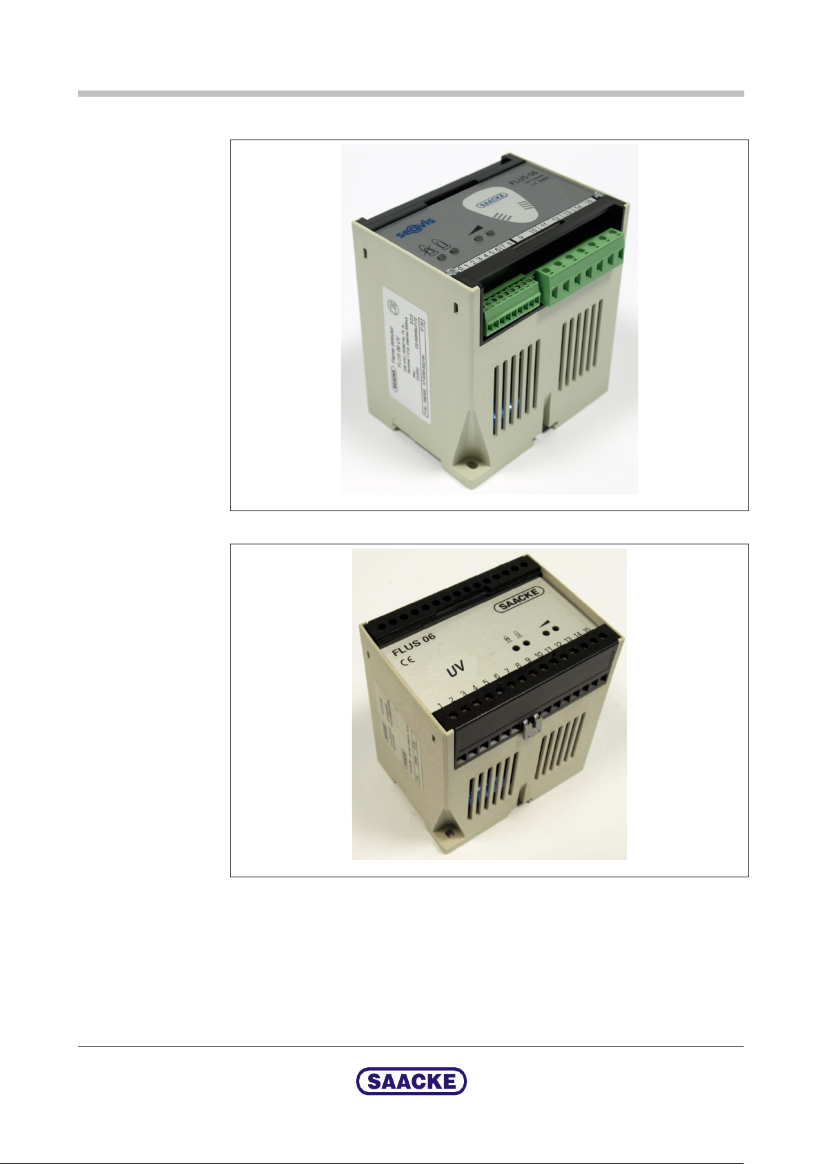
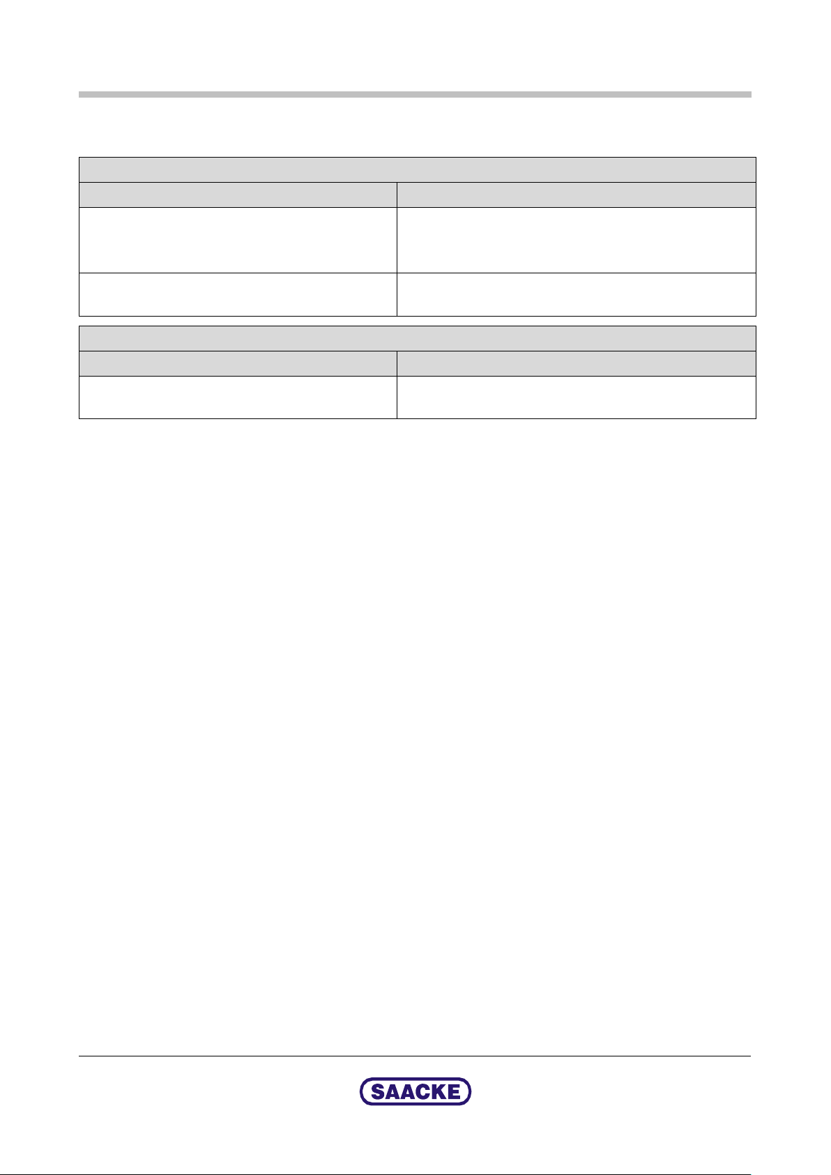
5.2 Flame Monitor FLUS 06 UV
Fig. 2: Flame monitor FLUS 06 UV (as of Revision 3)
Fig. 3: Flame monitor FLUS 06 UV (up to Revision 2)
12 / 26
The flame monitor processes the electrical signal variable that it receives from the
flame scanner and outputs a status message for the flame signal by means of
LEDs and potential-free contacts.
The flame monitor is self-monitored, i.e. it processes the input signals from the
flame scanner via two separate, alternately controlled channels whose output
levels are continuously compared with anticoincidence.
Technical Documentation
1-8254-8054b-02 2014-03-05

FLUS 06 UV / FLS 09 UV
Design and Function
H016
H015
Display and operating controls
Fig. 4: Front panel of flame monitor (as of Revision 3)
Fig. 5: Front panel of flame monitor (up to Revision 2)
2014-03-05
Technical Documentation
1-8254-8054b-02 13 / 26

Design and Function
FLUS 06 UV / FLS 09 UV
H017
Fig. 6: Detail: LEDs on the front panel
When the operating voltage has been switched on on the control cabinet, the flame
monitor is ready for operation after about 10 seconds.
In the initial state (“Flame OFF”) the red LED1 is lit.
If the flame is detected when the burner has ignited, the red LED1 goes out.
Instead the green LED2 is lit (“Flame ON”).
Note
The green LED2 flickers with the rhythm of the self-monitoring, this is not a fault
message.
The green LED3 and LED4 are used to indicate the flame intensity:
If the flame signal is weak, only LED3 is lit.
If the flame signal is strong, LED3 and LED4 are lit.
Note
The position and alignment of the flame scanner, which is set during
commissioning, are decisive for the intensity of the flame signal.
14 / 26
Technical Documentation
1-8254-8054b-02 2014-03-05

FLUS 06 UV /
FLS 09 UV Installation
6 Installation
The flame scanner is mounted on the burner. The flame scanner must be aligned
in such a way that
it perceives the first third of the flame during burner operation
it reliably detects the flame in the entire capacity range of the burner
This was already taken into account for SAACKE burners during the design phase.
The position of the flame scanner(s) has therefore already been specified in the
design. Only the insertion depth and the alignment of the flame scanner (lens)
must be optimised specifically for the plant during commissioning of the burner.
The flame scanner is already correctly connected to the flame monitor ex works.
The flame monitor is also already connected in the component connection box.
2014-03-05
Technical Documentation
1-8254-8054b-02 15 / 26

Maintenance
FLUS 06 UV / FLS 09 UV
7 Maintenance
7.1 Cleaning the FLS 09 UV Flame Scanner / Running the Shut-off Check
The lens of the flame scanner must be cleaned at specific intervals depending on
the operating conditions of the firing plant.
To do this, the flame scanner must be removed.
We recommend checking the “Flame fault safety shut-off” safety function (shut-off
check) at the same time. Before you start, carefully read the operational sequence
description of the shut-off check.
Note
The shut-off check can only be run while the burner is in operation.
If you would like to clean the lens only, without running the shut-off check, switch
the burner off before you remove the flame scanner.
The sequence including the shut-off check is described below.
Warning!
Plant operation without “Flame monitoring” safety function!
During the shut-off check you are instructed to remove the flame scanner during
operation.
Remember: While the flame scanner is removed, the flame is not monitored, i.e.
the “Flame monitoring” safety function is inactive during this time.
Therefore do the steps described below carefully and quickly.
Warning! Risk of injuries from parti cles in the air!
When removing the flame scanner, air containing particles may escape. We
recommend wearing safety goggles.
Caution!
The shut-off check will trigger a safety shut-off! Get clearance from the plant
manager before starting the check.
16 / 26
Technical Documentation
1-8254-8054b-02 2014-03-05

FLUS 06 UV / FL
S 09 UV Maintenance
TX080
Fig. 7: Flame scanner with mount
1 Flame scanner
2 Mount (made of polycarbonate, transparent)
3 Clamping screw
4 Position screw (on the burner)
5 Mounting screw
6 Adapter (on the burner, example)
If the flame scanner monitors the ignition flame:
Start the burner and wait until the ignition flame is burning.
If the flame scanner monitors the main flame:
Run the burner to the low-load position.
Unscrew the two mounting screws (5).
Caution!
The position screws (4) and the clamping screw (3) stay screwed in!
Pull out the flame scanner with its mount.
Warning!
Plant operation without the “Flame monitoring” safety function!
While the flame scanner is removed, the flame is no longer monitored, i.e. the
“Flame monitoring” safety function is inactive during this time.
Cover the lens. When doing so, be sure not to soil or scratch the lens.
This must trigger a safety shut-off within one second at the latest.
2014-03-05
Technical Documentation
1-8254-8054b-02 17 / 26

Maintenance
FLUS 06 UV / FLS 09 UV
Warning!
Plant operation without the “Flame monitoring” safety function!
If no safety shut-off is triggered during the shut-off check, press the emergency
stop button on the plant.
Observe the chapter entitled “Troubleshooting”.
Only restart the plant when you are sure that the flame detection system is
functioning properly.
Check whether the lens is dirty. Clean it if required.
Caution!
The lens is made of glass. Take care not to scratch the lens. Use only cleaning
materials that do not damage the surface of the lens.
Mount the flame scanner (including the mount).
Reset the burner at the burner control system.
7.2 Flame Monitor FLUS 06 UV
The flame monitor is maintenance-free.
If the front panel is dirty...
Clean it with a clean cloth and one of the cleansers listed below.
Then wipe it off with a clean cloth.
Approved cleansers: Ethyl alcohol, household cleanser, isopropanol, window
cleaner
Not approved cleansers: Solvents (dichloromethane, ether, chloroform), acetone,
butanone, acids, undiluted alkalis
18 / 26
Technical Documentation
1-8254-8054b-02 2014-03-05
FLUS 06 UV / FLS 09 UV
Troubleshooting
8 Troubleshooting
Fault message “Flame fault” during operation
Possible cause Measures
Flame not correct (various causes possible)
Follow the operating instructions for the burner.
If in doubt: Contact SAACKE Service (address on back
of the document).
Flame scanner / flame monitor defective
Shut-off check not successful
Possible cause Measures
Flame scanner / flame monitor defective
Contact SAACKE Service (address on back of the
document).
Contact SAACKE Service (address on back of the
document).
2014-03-05
Technical Documentation
1-8254-8054b-02 19 / 26
Repair
FLUS 06 UV / FLS 09 UV
9 Repair
Warning!
Both the flame scanner and the flame monitor are safety-related components. If
they are defective, they must not be repaired, they must be replaced.
The casings of the flame scanner and flame monitor must not be opened.
Use only original spare parts as replacements. SAACKE Service is at your disposal
for more detailed information. You will find our contact address on the back of this
document.
After replacing the flame scanner and/or the flame monitor, run at least one shutoff check for safety reasons.
20 / 26
Technical Documentation
1-8254-8054b-02 2014-03-05

FLUS 06
UV / FLS 09 UV Technical Data
H013
(Shield)
FLS 09 UV-5L
FLS 09 UV-5
10 Technical Data
10.1 Flame Scanner FLS 09 UV
2014-03-05
Fig. 8: Dimensions of flame scanner
Technical Documentation
1-8254-8054b-02 21 / 26

Technical Data
FLUS 06 UV / FLS 09 UV
Weight 400 g
Ambient conditions (transport) -20 to +70°C
Maximum humidity 80% at 35°C
Ambient conditions (operation) -10 to +60°C
Maximum humidity 80% at 35°C
Viewing angle
Protection class IP65
Detectable spectral radiation range 215 – 360 nm
Detectable pulsation frequency 10 – 200 Hz
Installation position any
Connection cable
Stranded hookup wire SABIX D315 FRNC special (6-core), 6 x 1 x 0.5 mm²
(AWG20), length 3 m
Extension up to maximum 100m possible
The PK (pink) wire of the connection cable must not be extended.
Approx. ± 5° to the optical axis
22 / 26
Technical Documentation
1-8254-8054b-02 2014-03-05
FLUS 06 UV / FLS 09 UV
Technical Data
H030
H014
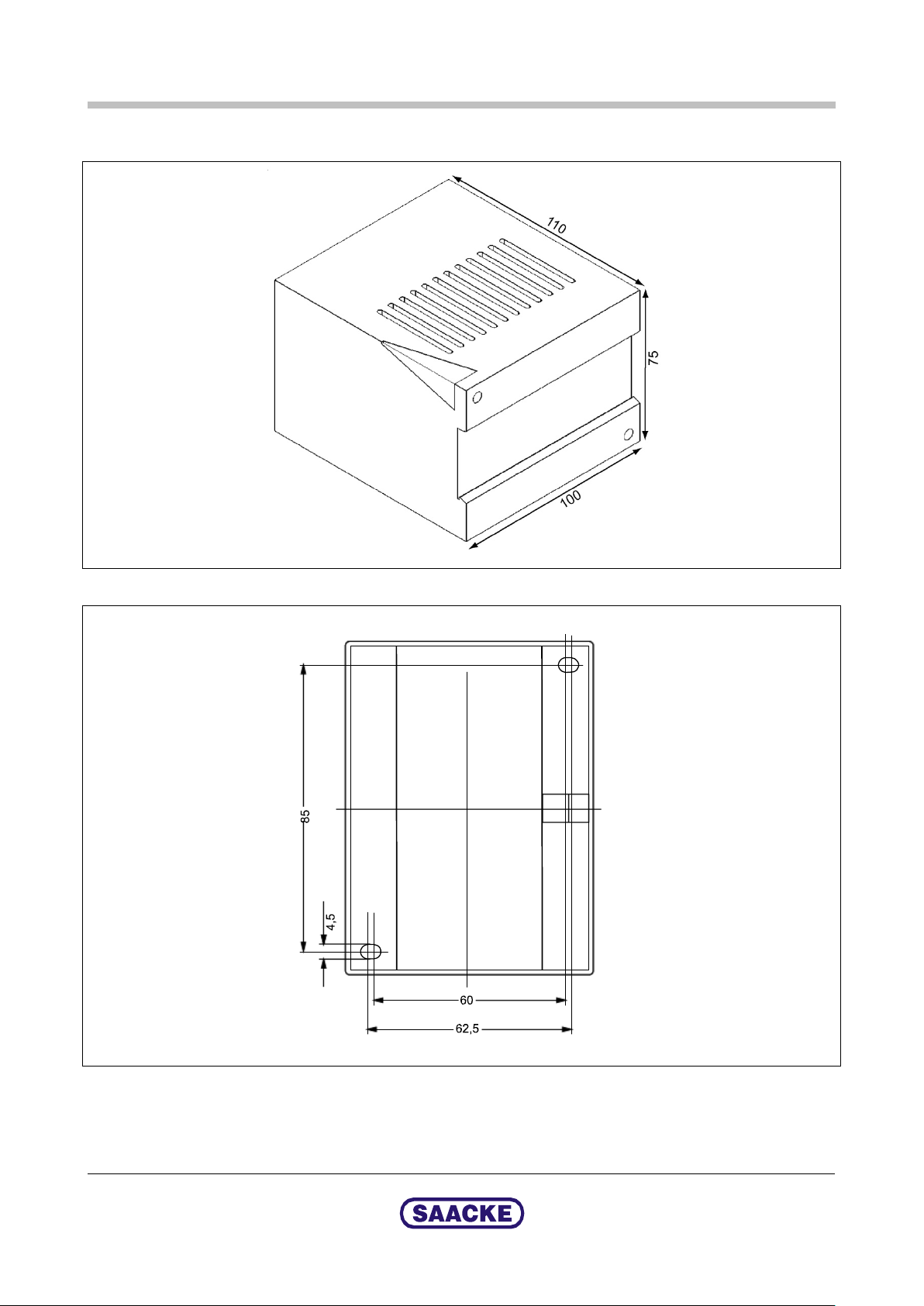
10.2 Flame Monitor FLUS 06 UV
Fig. 9: Dimensions of flame monitor (1)
2014-03-05
Fig. 10: Dimensions of flame monitor (2), view from below
Technical Documentation
1-8254-8054b-02 23 / 26

Technical Data
FLUS 06 UV / FLS 09 UV
1
Weight 500 g
Ambient conditions (transport) -20 to +70°C
Maximum humidity 80% at 35°C
Ambient conditions (operation) -10 to +60°C
Maximum humidity 80% at 35°C
Installation type In the control cabinet / control panel or control box
Mounting type On top-hat rail, alternatively via mounting holes
Installation position Any
Protection class Up to Revision 2: IP20
As of Revision 3: IP20 if plug inserted
Safety time
Operating voltage 230 V AC (-15 % to +10 %),
Power consumption approx. 5 VA
Safe output contact
for safety function
(potential-free, open when deenergised)
≤ 1 s
115 V AC (-15 % to +10 %) optional,
50 or 60 Hz
Terminals 11 and 12
Permitted switching voltage Min. 6 V AC / 6 V DC
Max. 250 V AC / 30 V DC
Permitted switching current Min. 1 mA (with contact limit
Switching power Max. 15 W DC
load 50 mA)
Max. 0. 5 A
Max. 125 VA AC
(when cos
ϕ = 0.4)
Non-safe output contact
for indication function
(potential-free, open when deenergised)
Measurement output for flame
intensity
Feed to flame scanner Voltage 22 – 37 V DC
1
Must be fused externally. The fuse is not included in the scope of delivery
Terminals 9 and 10
Permitted switching voltage Min. 6 V AC / 6 V DC
Max. 250 V AC / 30 V DC
Permitted switching current Min. 40 mA
Max. 0.5 A
Fuse
Terminals 7 and 8
Output current 0 – 20 mA (direct current)
Max. resistance
No-load direct voltage 22 – 26 V DC
Intrinsic error
Short-circuit current 30 mA (max. 1 min)
0.5 A
500
± 2%
Ω
24 / 26
Technical Documentation
1-8254-8054b-02 2014-03-05


For local contacts please see www.saacke.com
a
SAACKE GmbH
Suedweststrasse 13
28237 Bremen
Germany
Tel.: +49 421 6495-0
Fax: +49 421 6495-5224
info@saacke.de
www.saacke.com
SAACKE Service:
Industrial Solutions
Supportline: +800-1002001
or +49 421 6495-5201
spares-industrial@saacke.com
service-industrial@saacke.com
Marine Systems
Hotline Germany: +49 421 6495-5229
Hotline Worldwide: +1 954 767 0309
spares-marine@saacke.com
service-marine@saacke.com
 Loading...