

SA SA AK310 Service Manual
Service Manual
TOP NEXT
ORDER NO. MD0212275C3
CD Stereo System
SA-AK310GC
SA-AK310GN
Colour
(S)... Silver Type
TAPE SECTION :
SG-2W MECHANISM SERIES
Specifications
AMPLIFIER SECTION
Power output
10% Total harmonic distortion
1kHz, both channels driven
(Low channel) 55 W per channel (6Ω )
10kHz, both channels driven
(High channel) 55 W per channel (6Ω )
Total Bi-Amp power 110 W per channel
Input sensitivity
AUX 250 mV
Input Impedance
AUX 13.3 kΩ
FM TUNER SECTION
Frequency range 87.50 - 108.00 MHz (50 kHz steps)
Sensitivity 2.5µ V (IHF)
S/ N 26 dB 2.2µ V
Antenna terminal(s) 75Ω (unbalanced)
AM TUNER SECTION
Frequency range 522 - 1629 kHz (9 kHz steps)
520 - 1630 kHz (10 kHz steps)

distribution is a violation of law.
Sensitivity
S/ N 20 dB (at 999 kHz) 560µ V/ m
CASSETTE DECK SECTION
Track system 4 track, 2 channel
Heads
Record/ playback Solid permalloy head
Erasure Double gap ferrite head
Motor DC servo motor
Recording system AC bias 100 kHz
Erasing system AC erase 100 kHz
Tape speed 4.8 cm/ s (1 7/ 8 ips)
Overall frequency response (+ 3 dB, -6 dB at DECK OUT)
NORMAL (TYPE I) 35 Hz - 14 kHz
S/ N 50 dB (A weighted)
Wow and flutter 0.18% (WRMS)
Fast forward and rewind time Approx. 120 seconds with
C-60 cassette tape
CD SECTION
Sampling frequency 44.1 kHz
Decoding 16 bit linear
Beam source/ wave length Semiconductor laser/ 780 nm
Number of channels Stereo
Frequency response 20 Hz - 20 kHz (+ 1, -2 dB)
Wow and flutter Below measurable limit
Digital filter 8 fs
D/ A converter MASH (1 bit DAC)
GENERAL
Power Supply
For GC only AC 110/ 127/ 220-230/ 240 V, 50/ 60Hz
For GN only AC 230-240 V, 50Hz
Power consumption
For GC only 172 W
For GN only 170 W
Power Consumption in standby mode
For GC only 0.85 W
For GN only 0.5 W
Dimensions (W x H x D) 250 x 330 x 370 mm
Mass
For GC only 7.8 kg
For GN only 7.0 kg
SYSTEM
SC-AK310 (GC) Music center: SA -AK310 (GC)
Speaker: SB-AK310 (GC)
SC-AK310 (GN) Music center: SA-AK310 (GN)
Speaker: SB-AK310 (GC)
Notes:
1. Specifications are subject to change without notice. Mass and dimensions are aproximate.
2. Total harmonic distortion is measured by the digital spectrum analyzer.
3. The labels“ HIGH ” and“ LOW” on the rear of the speakers refer to High frequency and Low frequency.
© 2002 Matsushita Electronics (S) Pte. Ltd. All rights reserved. Unauthorized copying and

TOP
NEXT

1 Before Use
TOP PREVIOUS NEXT
screwdriver to set the voltage selector (on the rear panel) to the voltage setting for the
Note that this unit will be seriously damaged if this setting is not made correctly. (There is no
TOP
PREVIOUS
NEXT
Be sure to disconnect the mains cord before adjusting the voltage selector.
Use a minus(-)
area in which the unit will be used. (If the power supply in your area is 117V or 120V, set to the
“127V” position.)
voltage selector for some countries, the correct voltage is already set.)

2 Before Repair and Adjustment
TOP PREVIOUS NEXT
TOP
PREVIOUS
NEXT
Disconnect AC power, discharge Power Supply Capacitors C520 and C540 through a 10Ω, 5W
resistor to ground.
DO NOT SHORT-CIRCUIT DIRECTLY (with a screwdriver blade, for instance), as this may
destroy solid state devices.
After repairs are completed, restore power gradually using a variac, to avoid overcurrent.

3 Protection Circuitry
TOP PREVIOUS NEXT
The function of this circuitry is to prevent circuitry damage if, for example, the positive and negative
Note:
TOP
PREVIOUS
NEXT
The protection circuitry may have operated if either of the following conditions are noticed:
No sound is heard when the power is turned on.
Sound stops during a performance.
speaker connection wires are
“shorted”, or if speaker systems with an impedance less than the indicated rated impedance of the
amplifier are used.
If this occurs, follow the procedure outlines below:
1. Turn off the power.
2. Determine the cause of the problem and correct it.
3. Turn on the power once again after one minute.
When the protection circuitry functions, the unit will not operate unless the power is first turned off
and then on again.

4 Accessories
TOP PREVIOUS NEXT
TOP
PREVIOUS
NEXT
Remote control transmitter
FM indoor antenna
AC power supply cord (For GC only)
AC power supply cord (For GN only)
AM Loop antenna
Power plug adaptor
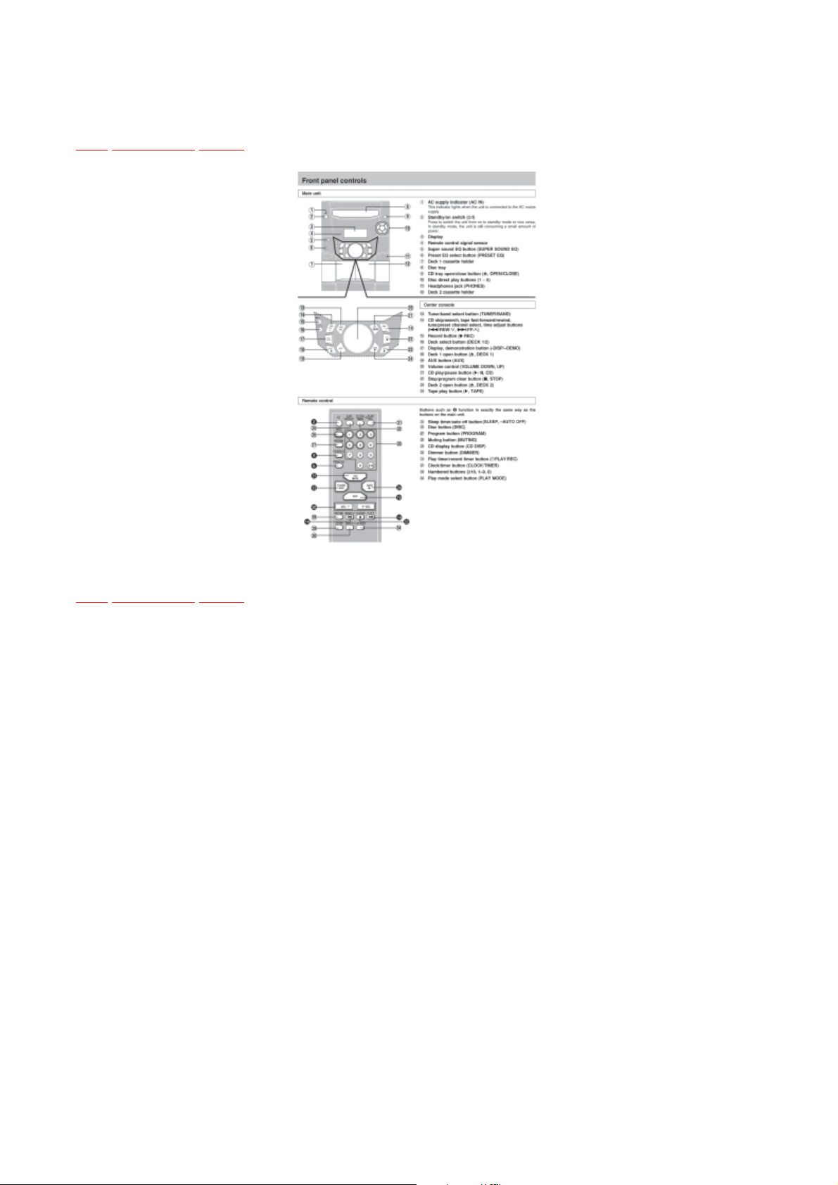
5 Operation Procedures
TOP PREVIOUS NEXT
TOP
PREVIOUS
NEXT

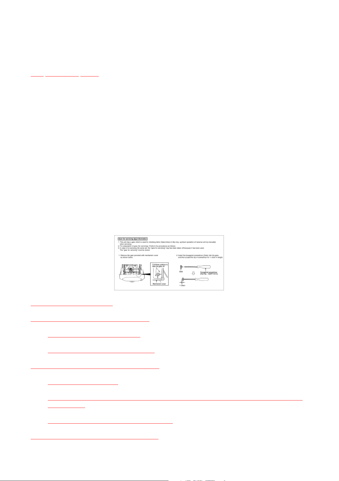
6 Handling Precautions For Traverse Deck
TOP PREVIOUS NEXT
Do not subject the traverse deck (optical pickup) to static electricity as it is extremely sensitive
The static electricity of your clothes will not be grounded through the wrist strap. So, take care
connections.
The laser diode in the traverse deck (optical pickup) may break down due to potential difference
caused by static electricity of clothes or human body.
So, be careful of electrostatic breakdown during repair of the traverse deck (optical pickup).
Handling of traverse deck (optical pickup)
1.
to electrical shock.
2. The short land between the No.4(LD) and No.5(GND) pins on the flexible board (FFC) is
shorted with a solder build-up to prevent damage to the laser diode.To connect to the PC
board, be sure to open by removing the solder build-up, and finishthe workquickly.
3. Take care not to apply excessive stress to the flexible board (FFC).
4. Do not turn the variable resistor (laser power adjustment). It has already been adjusted.
Grounding for electrostatic breakdown prevention
1. Human body grounding
Use the anti-static wrist strap to discharge the static electricity from your body.
2. Work table grounding
Put a conductive material (sheet) or steel sheet on the area where the traverse deck
(optical pickup) is placed, and ground the sheet.
Caution :
not to let your clothes touch the traverse deck (optical pickup).
Caution when Replacing the Traverse Deck :
The traverse deck has a short point shorted with solder to protect the laer diode against
electroststics breakdown. Be sure to remove the solder from the short point before making

TOP
PREVIOUS
NEXT
7 Operation Checks and Component
Replacement Procedures
7.4 Main Component Replacement Procedures
TOP PREVIOUS NEXT
“ATTENTION SERVICER”
Some chassis components may have sharp edges.
Be careful when disassembling and servicing.
1. This section describes procedures for checking the operation of the major printed circuit
boards and replacing the main components.
2. For reassembly after operation checks or replacement, reverse the respective procedures.
Special reassembly procedures are described only when required.
3. Select items from the following index when checks or replacement are required.
Warning:
This product uses a laser diode. Refer to caution statement Precaution of Laser Diode.
7.1 Checking for Main P.C.B.
7.2 Disassembly for the CD changer ass ’ y
7.2.1 Disassembly for the CD Lid
7.2.2 Disassembly for CD changer unit
7.3 Checking for the unit operational condition
7.3.1 Initial setting of CD
7.3.2 Checking for the CD Servo P.C.B., Panel P.C.B., Deck P.C.B., Transformer P.C.B. and
Power P.C.B.
7.3.3 Replacement of the Power Amplifier IC

7.4.1 Replacement of the Traverse Deck
7.5 Replacement for the disc tray
TOP
PREVIOUS
NEXT
7.6 Disassembly and reassembly for mechanism base drive unit
7.7 Replacement for the motor ass ’ y
7.8 Replacement for the pinch roller ass ’ y and head block
7.9 Replacement for the Deck motor ass ’ y, capstan belt A, capstan belt B and winding belt
7.10 Replacement for the CD motor ass ’ y, capstan belt A, capstan belt B and winding belt
7.11 Replacement for the cassette lid ass ’ y
7.12 Measure for tape trouble
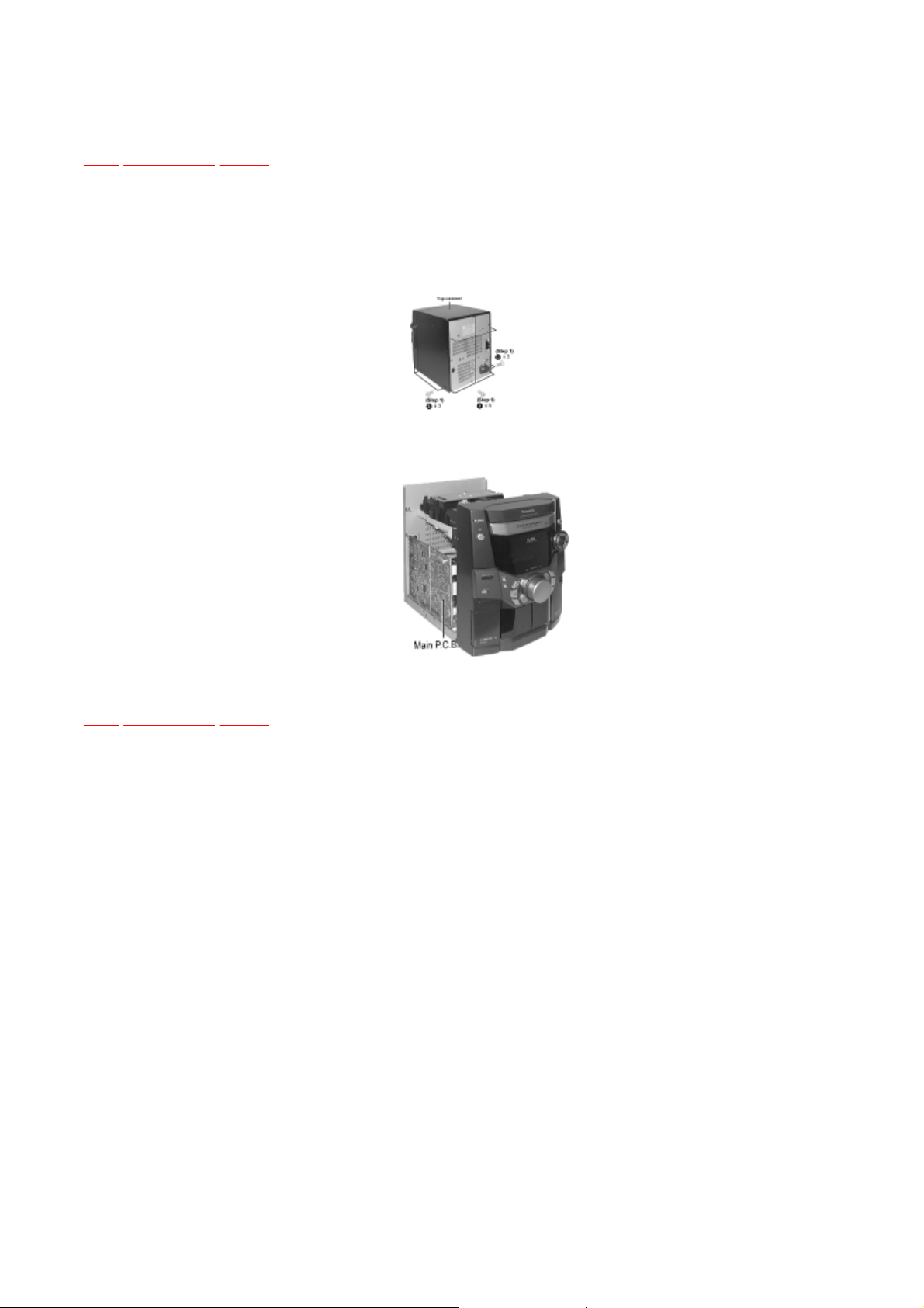
7.1 Checking for Main P.C.B.
TOP PREVIOUS NEXT
TOP
PREVIOUS
NEXT
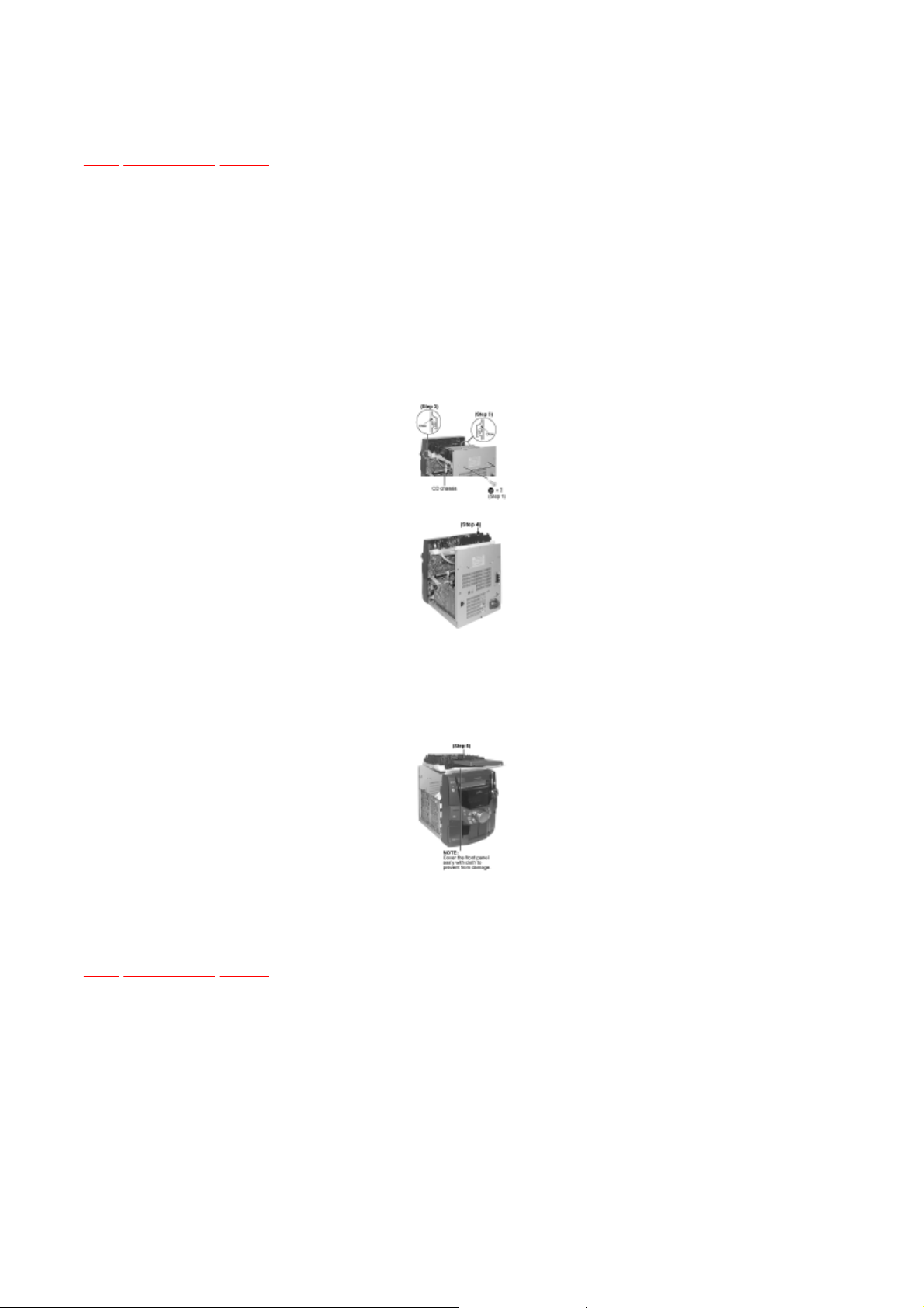
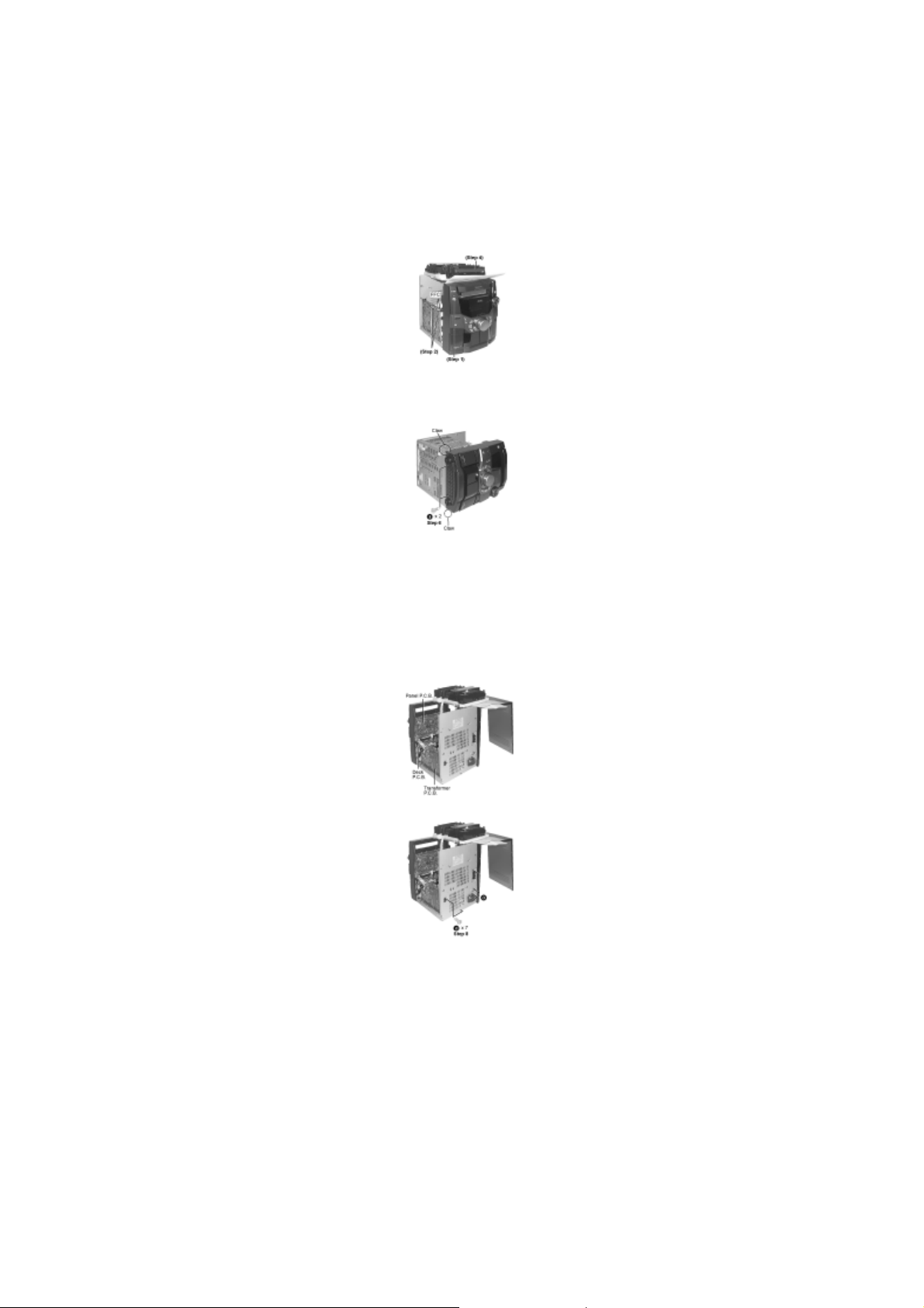
Step 1 Remove 3 screws each side and 5 screws at rear panel.
Step 2 Lift up both sides of cabinet ass’y, push the cabinet ass’y toward the rear and remove the
cabinet ass’y.
Checking the Main P.C.B. as shown below.

7.2 Disassembly for the CD changer ass
’ y
TOP PREVIOUS NEXT
TOP
PREVIOUS
NEXT
(The CD changer unit can be removed after the CD Lid is removed)
7.2.1 Disassembly for the CD Lid
7.2.2 Disassembly for CD changer unit

7.2.1 Disassembly for the CD Lid
TOP PREVIOUS NEXT
Step 6
Press the OPEN/CLOSE button, the disc tray will be close.
Follow the (Step 1) - (Step 2) of Item 7.1.
When opening the disc tray automatically (Using Power Supply)
Step 1 Connect the AC power cord.
Step 2 Press the POWER button to power up the main unit.
Step 3 Press the OPEN/CLOSE button, the disc tray will be open automatically.
Step 4 Release the 2 claws, and then remove the CD Lid.
Step 5 Press the POWER button to turn the power on.
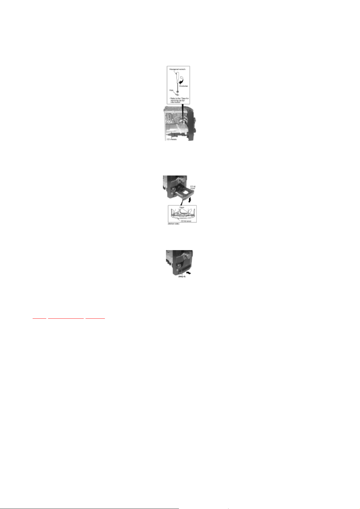
[Open the disc tray manually (Using service tools)]
Step 1 Upset the unit as shown below.
Insert the gear tool into the hole on the underside of CD chasis and then rotate in the direction
TOP
PREVIOUS
NEXT
Step 2
of arrow. The disc tray will be open.
Step 3 Release the 2 claws, and then remove the CD lid cover.
Step 4 Push the disc tray.
7.2.2 Disassembly for CD changer unit
TOP PREVIOUS NEXT
TOP
PREVIOUS
NEXT
Follow the (Step 1) - (Step 2) of Item 7.1.
Follow the Disassembly for the CD Lid of Item 7.2.1.
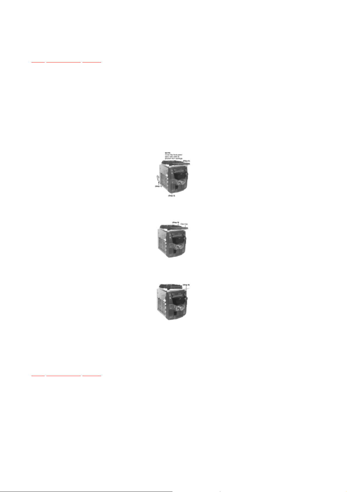
Step 1 Remove 2 screws at rear cabinet as show below.
Step 2 Lift up the mechanism unit cover, and then push in the mechanism unit cover.
Step 3 Release the claws of both ends, and then lift up the CD changer unit.
Step 4 Upset the CD changer unit.
Step 5 Place the CD changer unit on the unit.
<The preparation of checking procedures in operational condition is completed>

7.3 Checking for the unit operational condition
TOP PREVIOUS NEXT
TOP
PREVIOUS
NEXT
(Place the unit horizontally when loading the CD changer unit.)
7.3.1 Initial setting of CD
7.3.2 Checking for the CD Servo P.C.B., Panel P.C.B., Deck P.C.B., Transformer P.C.B. and Power
P.C.B.
7.3.3 Replacement of the Power Amplifier IC
7.3.1 Initial setting of CD
TOP PREVIOUS NEXT
TOP
PREVIOUS
NEXT
Follow the (Step 1) - (Step 2) of Item 7.1.
Follow the Disassembly for the CD Lid of Item 7.2.1.
Step 1 Connect the AC power cord.
Step 2 Press POWER button to turn on power for main unit.
Step 3 Select the input select button to “CD”.
Step 4 Push the OPEN/CLOSE button, and then open the disc tray.
Step 5 Put the CD into the disc tray.
Step 6 Press the OPEN/CLOSE button 1, and then close the disc tray. (Then, the CD will load.)
<The initial setting of CD unit is completed.>
7.3.2 Checking for the CD Servo P.C.B., Panel
P.C.B., Deck P.C.B., Transformer P.C.B. and
The initial setting of CD unit must be completed. (Refer to the initial setting of CD unit in item
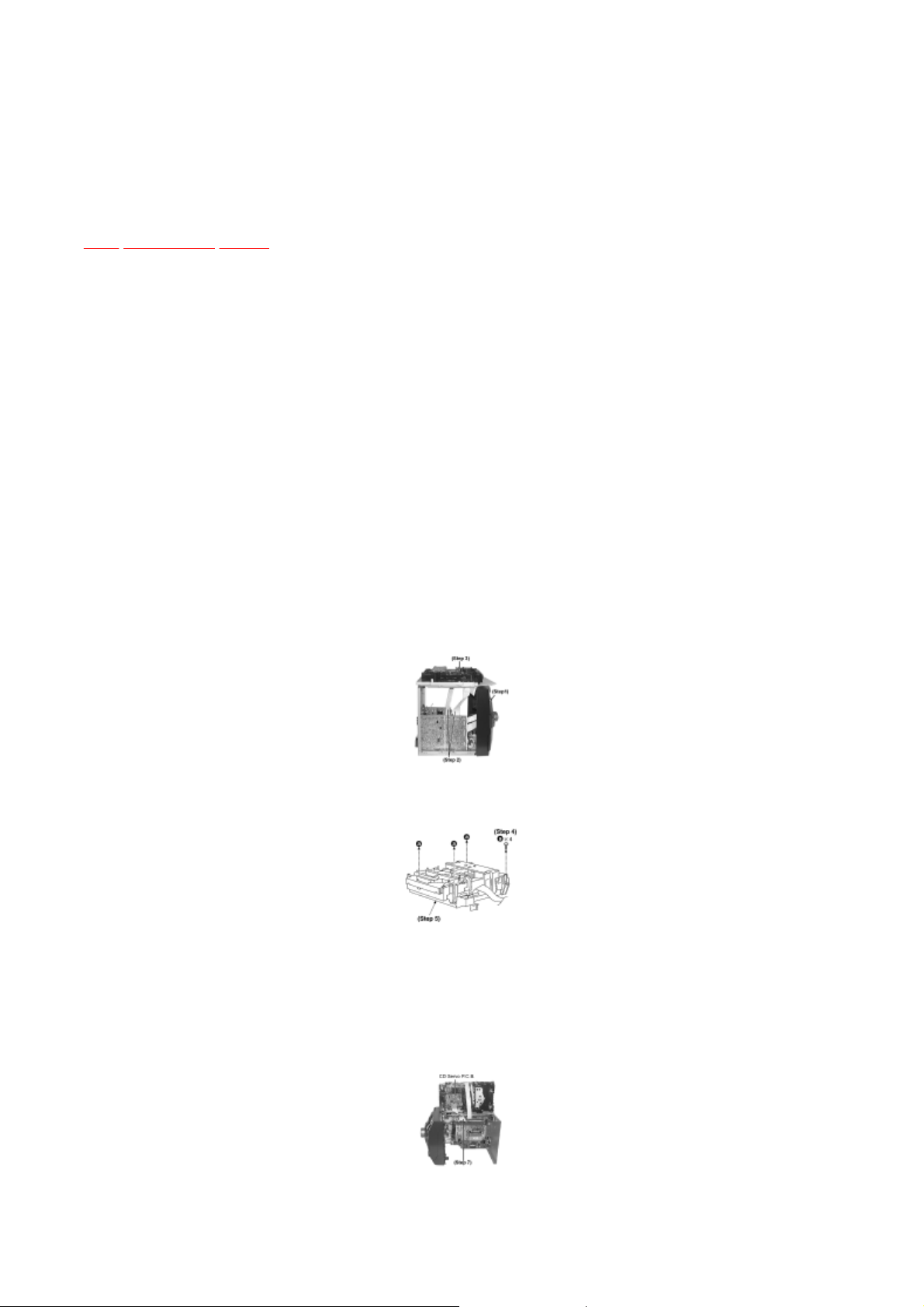
Step 7
Connect the FFC board (19 pin) from CD servo P.C.B..
Power P.C.B.
TOP PREVIOUS NEXT
Follow the (Step 1) - (Step 2) of Item 7.1.
Follow the Disassembly for the CD Lid of Item 7.2.1.
The initial setting of CD unit must be completed. (Refer to the initial setting of CD unit in
Item 7.3.1).
Check for CD Servo P.C.B.
7.3.1.)
Step 1 Push the power button and the power turns OFF.
Step 2 Remove the FFC boards.
Step 3 Remove the CD changer unit.
Step 4 Remove 4 screws.
Step 5 Remove the mechanism unit cover.
Check the CD Servo P.C.B. as shown below
Step 6 Lay the unit.
Step 1
Press the POWER button and the power turns off.
Step 2 Remove the connectors.
and Power P.C.B. of Item 7.3.2.
Step 3 Pull out the FFCs.
Step 4 Remove the CD changer unit.
Step 5 Lay the unit as shown below.
Step 6 Remove 2 screws.
Step 7 Release the 2 claws, and then draw the front panel ass’y.
Check the Panel P.C.B., Deck P.C.B. and Transformer P.C.B. as shown below
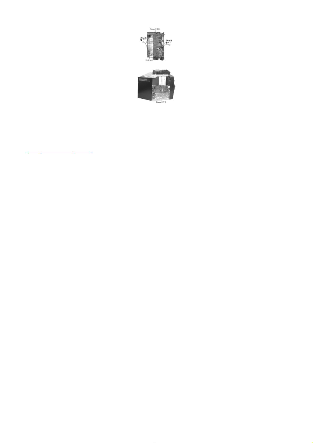
Step 8 Release the 6 screws, and then remove the rear cover.
Checking the Power P.C.B. as shown below
Follow the (Step 1) - (Step 2) of Item 7.1.
Follow the (Step 1) - (Step 6) of Disassembly for the CD Lid of Item 7.2.1.
Follow the (Step 1) - (Step 8) of Checking for Panel P.C.B.,Deck P.C.B., Transformer P.C.B.
NOTE:
TOP
PREVIOUS
NEXT
Insulate Power P.C.B. with insulation material to avoid short circuit.
7.3.3 Replacement of the Power Amplifier IC
TOP PREVIOUS NEXT
TOP
PREVIOUS
NEXT
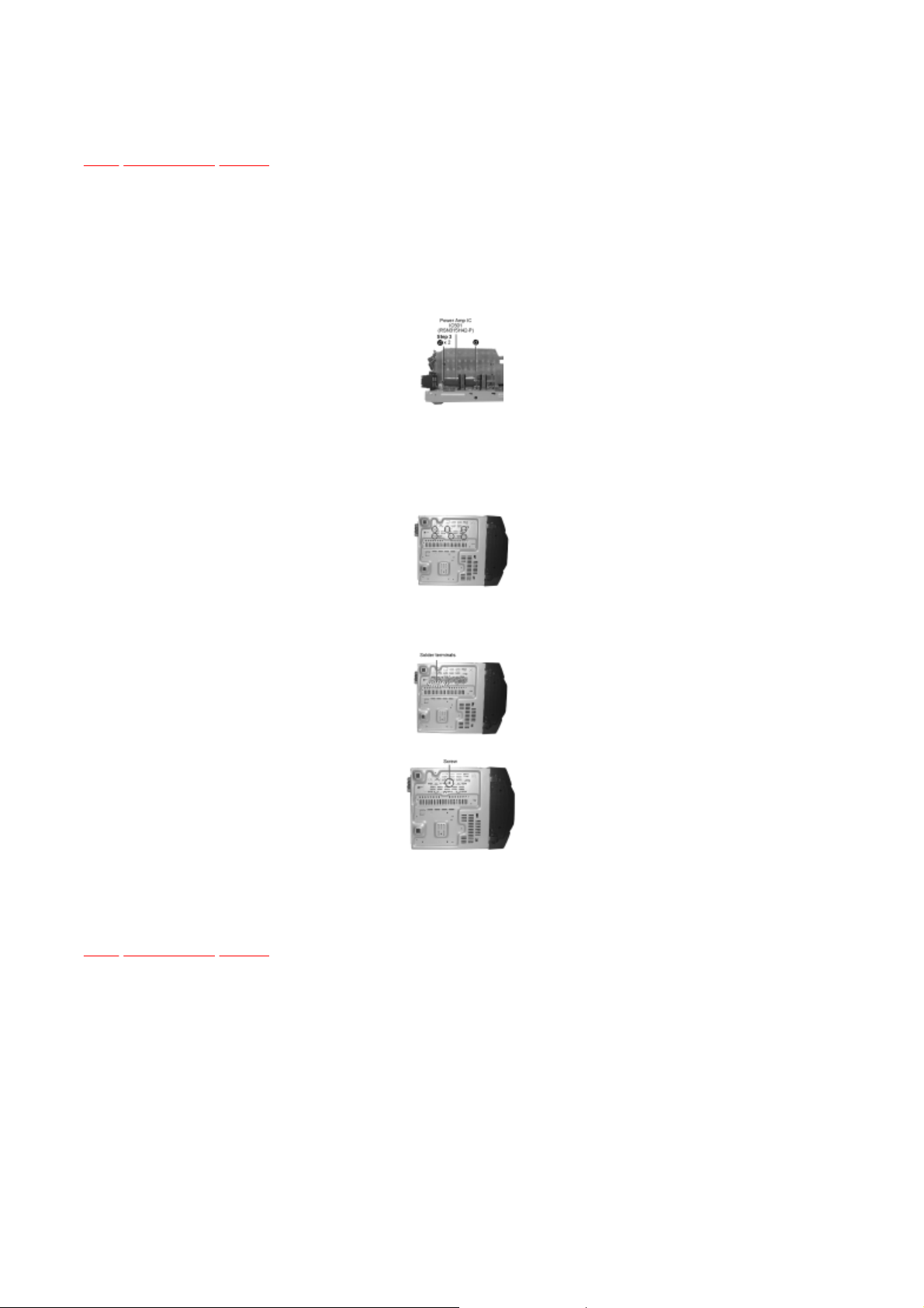
Checking the Power P.C.B.
Follow the (Step 1) - (Step 2) of Item 7.1.
Step 1 Remove the 2 screws fixed to the Power Amplifier IC.
Step 2 Remove 2 screws fixed to the Power Amplifier IC and Transistor Holders.
Step 3 Break the joint with a metal cutter as shown below.
Step 4 Unsolder the terminals of Power Amp IC, transistor and replace the component.
Step 5 Fix back the chasis with a screw as shown.

7.4 Main Component Replacement Procedures
TOP PREVIOUS NEXT
TOP
PREVIOUS
NEXT
7.4.1 Replacement of the Traverse Deck
7.4.1 Replacement of the Traverse Deck
TOP PREVIOUS NEXT
Rotate the hexagonal wrench in the direction of arrow (clockwise), and then open the disc tray
for a little amount.)
Follow the (Step 1) - (Step 2) of Item 7.1.
Follow the (Step 1) - (Step 6) of Disassembly for the CD Lid of Item 7.2.1.
Follow the disassembly instruction for the CD changer unit of Item 7.2.2.
Step 1 Push the power button and the power turns OFF.
Step 2 Remove the FFC boards.
Step 3 Remove the CD changer unit.
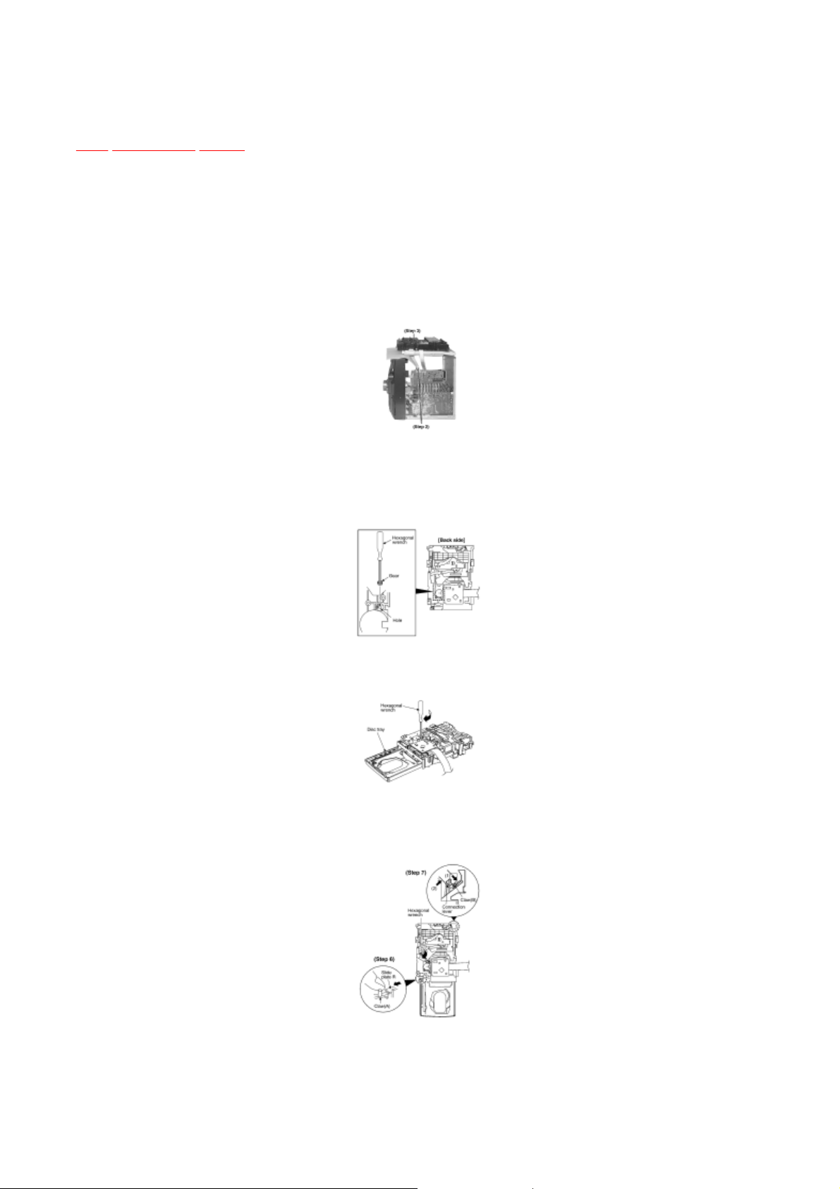
Step 4 Insert the gear with hexagonal wrench into the hole.
Step 5
fully.
Step 6 With pressing the claw (A), rotate the hexagonal wrench clockwise. (The slide plate R moves
Step 7
Pressing the claw (B) in the direction of arrow (1), the connection lever moves in the direction
of arrow (2).
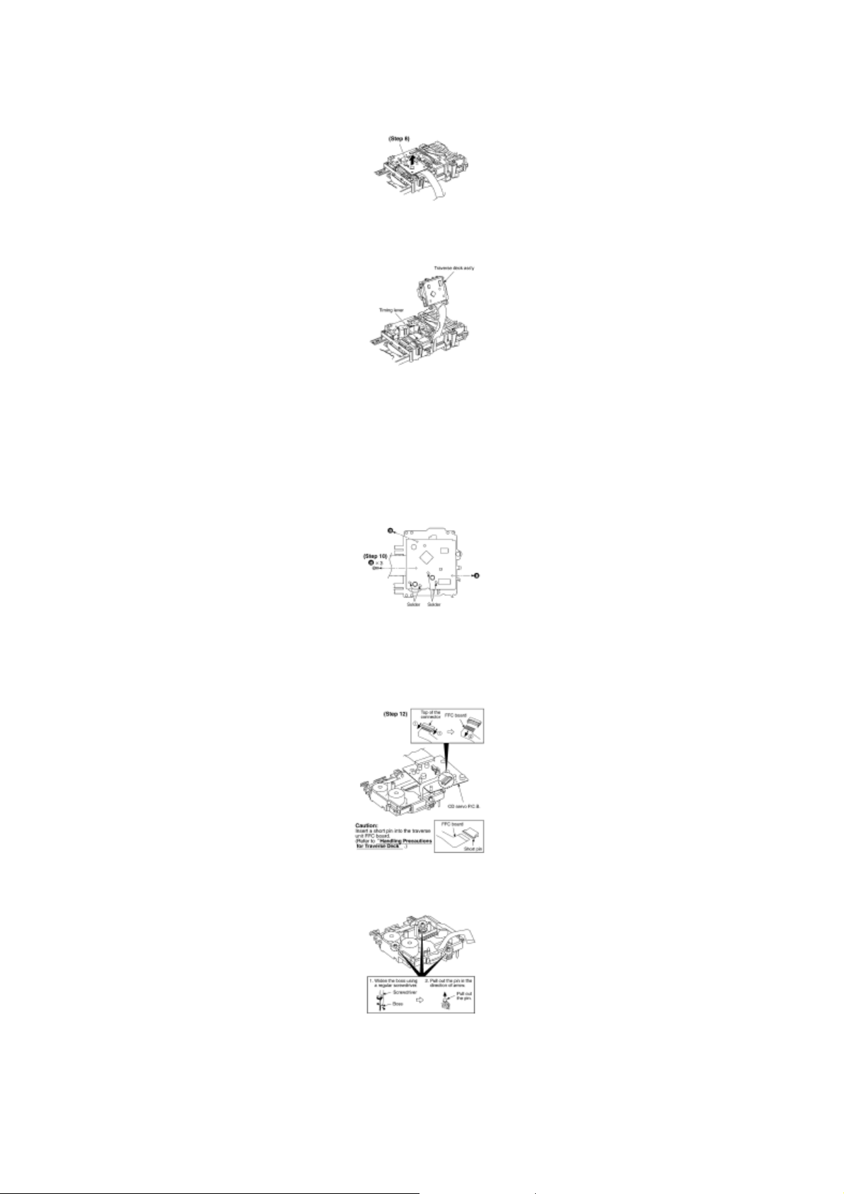
Step 13
Remove the pin.
Step 8 Lift up the traverse deck ass’y.
Step 9 Remove the traverse deck ass’y from the timing lever.
Caution:
When removing or inserting the traverse deck avoid touching the OPU lens and pressing onto the
turntable.
Step 10 Remove 3 screws.
Step 11 Unsolder the motor terminals (4 points).
Step 12 Remove the FFC board from the connector, and then remove the CD Servo P.C.B.

Note:
Step 2
Align the boss of traverse deck ass
’
y with the slot of traverse cam gear.
Step 14 Release the claw, and then remove the traverse deck ass’y.
Be careful not to lose the 3 floating spring because those will also be removed on removal of the
traverse deck ass’y.
Installation of the CD Servo P.C.B. after replacement
Step 1 Connect the FFC board.
Step 2 Install the CD servo P.C.B. in the traverse deck ass’y.
Step 3 Remove 3 screws.
Step 4 Solder.
Note for installation of the CD servo P.C.B.
Installation for traverse deck ass’y
Step 1 Install the traverse deck ass’y to the timing lever.
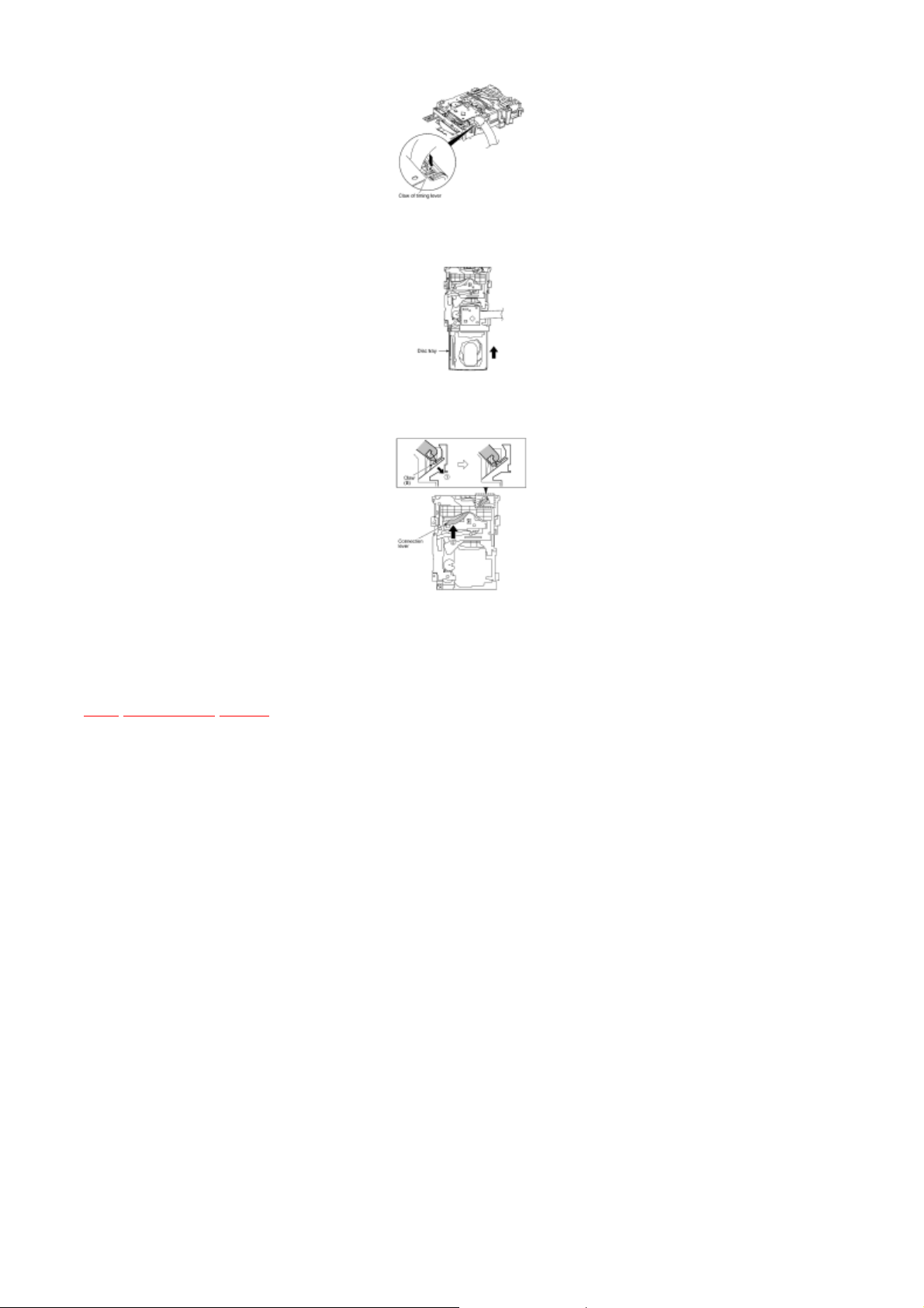
TOP
PREVIOUS
NEXT
Step 3 Force the claw of timing lever.
Step 4 Force the disc tray fully.
Step 5 With pressing the claw (B) in the direction of arrow (1), force the connection lever in the
direction of arrow (2).
7.5 Replacement for the disc tray
TOP PREVIOUS NEXT
Step 7
Rotate the hexagonal wrench in the direction of arrow, and then open the disc tray fully.
Follow the (Step 1) - (Step 2) of Item 7.1
Follow the Disassembly for the CD Lid of Item 7.2.1.
Follow the Disassembly for the CD Changer Unit of Item 7.2.2.
Follow the (Step 1) - (Step 8) of Item 7.4
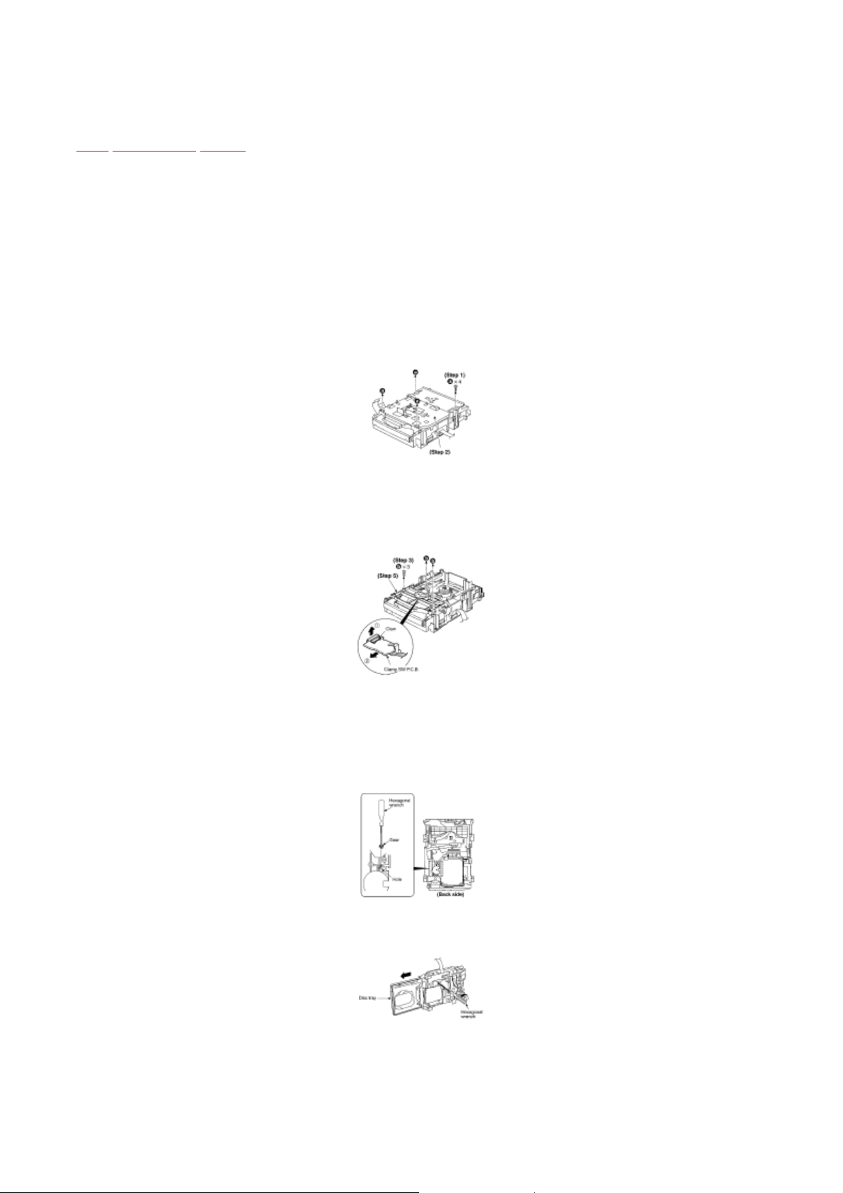
Step 1 Remove 4 screws.
Step 2 Remove the upper plate.
Step 3 Remove 3 screws.
Step 4 With lifting the claw in the direction of (1), draw the clamp SW P.C.B. in the direction of
arrow (2).
Step 5 Remove the mechanism cover.
Step 6 Insert the gear with hexagonal wrench into the hole.
NOTE:
Force the right guide bar of tray base manually not to move upwards.
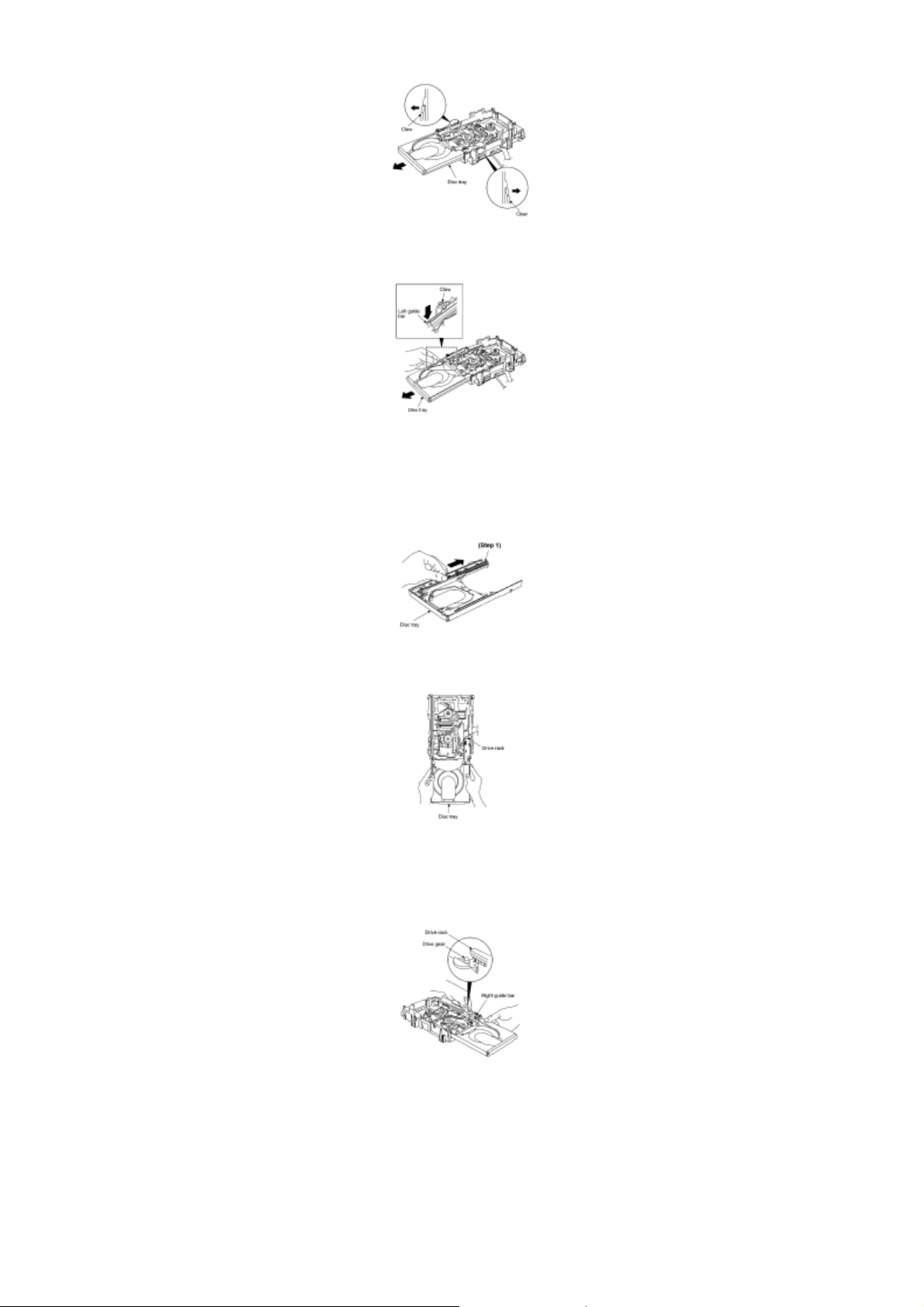
Step 8 Release the both claws, and then draw the disc tray.
Step 9 With forcing the left guide bar manually because the left guide bar interfers with claw, draw
the disc tray.
[Installation of the disc tray after replacement]
Step 1 Slide the drive rack fully in the direction of arrow.
Step 2 Holding the drive rack not to move, install the disc tray.
Step 3 Align the drive rack with the drive gear.
 Loading...