

Page 1
nt
R : Positive electrode on the side opposite to sprocket hole
1
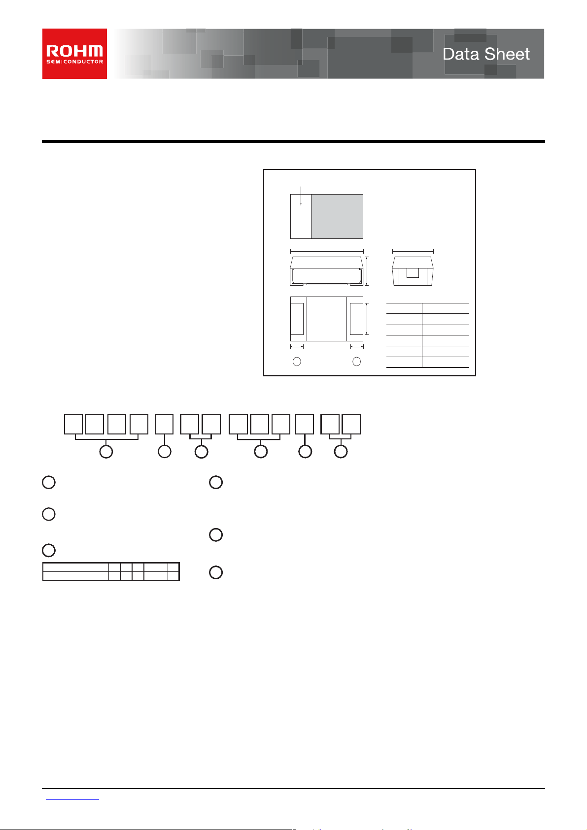
Chip tantalum capacitors (Fail-safe open structure type)
TCFG series P Case
Features Dimensions (Unit : mm)
1) Safety design by open function built - in.
2) Wide capacitance range
3) Screening by thermal shock.
Part No. Explanation
Anode mark
+
LW
H
W
2
SS
−
Dimensions
L
L
1
1
W
W
2
2
W
W
H
H
S
S
1
(Unit : mm)
Size
+
2.0 0.2
−
+
1.25 0.2
−
+
0.9 0.2
−
MAX.1.2
+
0.45 0.3
−
T C
11
Series name
TCFG
2
Case code
P
3
Rated Voltage
Rated voltage (
CODE
161
V)
F G
4
0G
P1A
2
6.30J101A161C201D25
5
3
4
Capacitance
0
4 5
M 8 R
6
Nominal capacitance in pF in 3 digits : 2significa
figure representing the number of 0's.
5
Capacitance tolerance
+
M :
20%
−
1E
Taping
8 : Reel width (8mm)
www.rohm.com
1/6
c
○
2012 ROHM Co., Ltd. All rights reserved.
2012.03 - Rev.G
Page 2
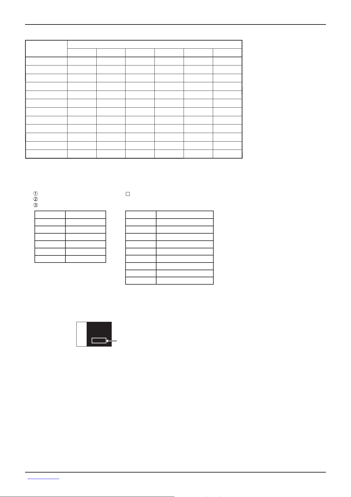
Remark) Case size codes (P) in the above show each size products line-up.
The indications listed below should be given on the surface of a capacitor.
w.
Capacitance range
(μF)
1.0 (105)
1.5 (155)
2.2 (225)
3.3 (335)
4.7 (475)
6.8 (685)
10 (106)
15 (156)
22 (226)
33 (336)
47 (476)
68 (686)
Marking
Data Sheet TCFG Series P Case
Rated voltage (V.DC)
4
P
P
P
P
P
P
P
6.3 10 16 20 25
PPPP
P
P
P
P
P
P
P
P
P
P
P
P
P
P
P
P
Polarity : The polarity should be shown by bar. (on the anode side)
Rated DC voltage : Due to the small size of P case, a voltage code is used as shown belo
Nominal capacitance
Voltage Code
g
A
C
D
E
Visual typical example (1) voltage code (2) capacitance code
[P Case] note 1)
Rated DC Voltage (V)
4
j
note 2) voltage code and capacitance code are variable with parts number
6.3
10
16
20
25
(1)
J
j
−
−
(2)
J
j
Capacitance Code
A
E
J
N
S
W
a
e
j
manufacture code
Nominal Capacitance (F)
1.0
1.5
2.2
3.3
4.7
6.8
10
15
22
www.rohm.com
2/6
c
○
2012 ROHM Co., Ltd. All rights reserved.
2012.03 - Rev.G
Page 3
e
it
it
it
e
h
e
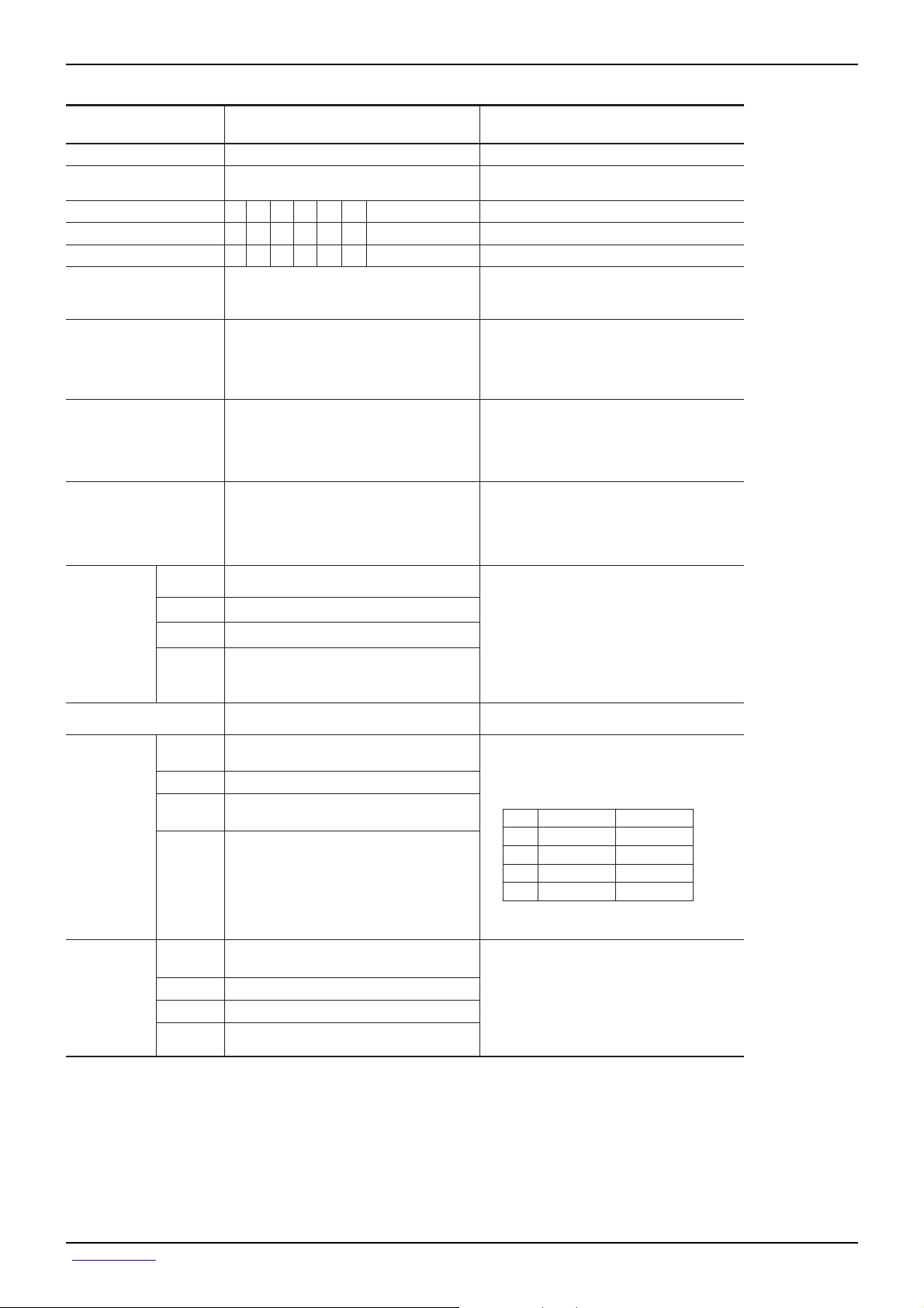
Characteristics
Item Performance
Operating Temperature
Maximum operating temperature
with no voltage derating
Rated Voltage (V.DC)
Category Voltage (V.DC)
Surge Voltage
DC leakage current
Capacitance tolerance
Tangent of loss angle
(Df, tanδ)
Impedance
Resistance to
soldering heat
Appearance
L.C
ΔC / C
tanδ
−55 °C to +125 °C
+85 °C
25
20
16106.34
16
13
106.342.5
321385
26
20
0.5μA or 0.01CV whichever is greater
(Shown in "Standard list")
Shall be satisfied allowance range.
±
20%
Shall be satisfied the voltage on "Standard list"
Shall be satisfied the voltage on "Standard list"
There should be no significant abnormality.
The indications should be clear.
Less than initial limit
Within
±
10
% of initial value
Less than 150% of initial limit
(based on JIS C5101-1 and JIS C5101-3)
Voltage reduction when temperature exceeds +85°C
at 85°C
°C
at 125
at 85°C
As per 4.9 JIS C 5101-1
As per 4.5.1 JIS C 5101-3
Voltage : Rated voltage for 1 min
As per 4.7 JIS C 5101-1
As per 4.5.2 JIS C 5101-3
Measuring frequency
Measuring voltage
Measuring circuit
As per 4.8 JIS C 5101-1
As per 4.5.3 JIS C 5101-3
Measuring frequency
Measuring voltage
Measuring circuit
As per 4.10 JIS C 5101-1
As per 4.5.4 JIS C 5101-3
Measuring frequency
Measuring voltage
Measuring circuit
As per 4.14 JIS C 5101-1
As per 4.6 JIS C 5101-3
Dip in the solder bath
Solder temp
Duration
Repetition
After the specimens, leave it at room temperatur
for over 24h and then measure the sample.
Test conditions
: 120±12Hz
: 0.5Vrms, +1.5V.DC
: DC Equivalent series circu
: 120±12Hz
: 0.5Vrms, +1.5V.DC
: DC Equivalent series circu
: 100±10kHz
: 0.5Vrms or less
: DC Equivalent series circu
: 260±10
: 5±0.5s
: 1
°C
Data Sheet TCFG Series P Case
Fail-Safe open unit actuation
Temperature
cycle
Moisture
resistance
Appearance
L.C
ΔC / C
tanδ
Appearance
L.C
ΔC / C
tanδ
320
°C
Within
There should be no significant abnormality.
The indications should be clear.
Less than initial limit
1 to 10F : within ±10
15 to 22F : within
Less than 150% of initial limit
There should be no significant abnormality.
The indications should be clear.
Less than initial limit
Within
Less than 150% of initial limit
− 20s
±
20
% of initial value
% of initial value
±
20
% of initial value
Dip in the solder bath
Solder temp : 320
As per 4.16 JIS C 5101-1
As per 4.10 JIS C 5101-3
Repetition : 5 cycles (1 cycle : steps 1 to 4)
without discontinuation.
Step
1
2
Room temp.
3
4
Room temp.
After the specimens, leave it at room temperatur
for over 24h and then measure the sample.
As per 4.22 JIS C 5101-1
As per 4.12 JIS C 5101-3
After leaving the sample under such atmospheric
condition that the temperature and humidity ar
60±2°C and 90 to 95%RH, respectively, for
±
12h level it at room temperature for over 24
500
and then measure the sample.
±
5°C
Temp. Time
+
−55 3
°C
−
3min. or less
+
125 2°C
−
3min. or less
+
30 3min
−
+
30 3min
−
www.rohm.com
3/6
c
○
2012 ROHM Co., Ltd. All rights reserved.
2012.03 - Rev.G
Page 4

h
e
h
e
e
Item Performance
Temperature
Stability
Temp.
ΔC / C
°C
−55
Within 0/−15%of initial value
Data Sheet TCFG Series P Case
Test conditions
(based on JIS C5101-1 and JIS C5101-3)
As per 4.29 JIS C 5101-1
As per 4.13 JIS C 5101-3
Surge
Voltage
Loading at
High
temperature
Terminal
Strength
tanδ
L.C
Temp.
ΔC / C
tanδ
L.C
Temp.
ΔC / C
tanδ
L.C
Appearance
L.C
ΔC / C
tanδ
Appearance
L.C
ΔC / C
tanδ
Capacitance
Appearance
Shall be satisfied the voltage on "Standard list"
−
+85
°C
Within +15/0%of initial value
Shall be satisfied the voltage on "Standard list"
Less than 1000% of initial limit
+125
°C
Within +20/0%of initial value
Shall be satisfied the voltage on "Standard list"
Less than 1250% of initial limit
There should be no significant abnormality.
Shall be satisfied the voltage on "Standard list"
Within
±
10%of initial value
Less than 150% of initial limit
There should be no significant abnormality.
Less than initial limit
±
10%of initial value
Within
Less than 150% of initial limit
The measured value should be stable.
There should be no significant abnormality.
As per 4.26 JIS C 5101-1
As per 4.14 JIS C 5101-3
Apply the specified surge voltage via the serial
resistance of 1kΩ every 5±0.5min.for 30±5 s. eac
time in the atmospheric condition of 85±2°C.
Repeat this procedure 1,000 times.
After the specimens, leave it at room temperatur
for over 24h and then measure the sample.
As per 4.23 JIS C 5101-1
As per 4.15 JIS C 5101-3
After applying the rated voltage for 1000+36/0
without discontinuation via the serial resistanc
of 3Ω or less at a temperature of 85±2°C, leav
the sample at room temperature/humidity for
over 24h and measure the value.
As per 4.35 JIS C 5101-1
As per 4.9 JIS C 5101-3
A force is applied to the terminal until it bends
to 1mm and by a prescribed tool maintain the
condition for 5s. (See the figure below.)
20
50
Thickness 1.6mm
F (Apply force)
R230
(Unit : mm)
1
45 45
Adhesiveness The terminal should not come off.
As per 4.34 JIS C 5101-1
As per 4.8 JIS C 5101-3
Apply force of 5N in the two directions shown
in the figure below for 10
±
1s after mounting
the terminal on a circuit board.
product
C105
YAA
www.rohm.com
4/6
c
○
2012 ROHM Co., Ltd. All rights reserved.
Apply force
a circuit board
2012.03 - Rev.G
Page 5

e
T
T
T
T
T
T
T
T
T
T
T
T
T
T
T
T
T
T
T
T
T
T
T
T
T
T
T
Data Sheet TCFG Series P Case
Item Performance
Dimensions Be based on "Dimensions"
(based on JIS C5101-1 and JIS C5101-3)
Measure using a caliper of JIS B 7505
Test conditions
Class 2 or higher grade.
Resistance to solvents The indication should be clear.
As per 4.32 JIS C 5101-1
As per 4.18 JIS C 5101-3
Dip in the isopropyl alcohol for 30±5s,
at room temperature.
Solderability
3/4 or more surface area of the solder coated
terminal dipped in the soldering bath should be
covered with the new solder.
As per 4.15.2 JIS C 5101-1
As per 4.7 JIS C 5101-3
Dip speed = 25±2.5mm/s
Pre-treatment (accelerated aging) : Leave th
sample on the boiling distilled water for 1h.
Solder temp. : 245±5°C
Duration : 3±0.5s
Solder : M705
Flux : Rosin 25%, IPA 75%
CapacitanceVibration
Appearance
Measure value should not fluctuate during the
measurement.
There should be no significant abnormality.
As per 4.17 JIS C 5101-1
Frequency : 10 to 55 to 10Hz/min.
Amplitude : 1.5mm
Time : 2h each in X and Y directions
Mounting : The terminal is soldered on a print
circuit board.
Table 1 standard list, TCFG series P Case
(%)
±
±
±
±
±
±
±
±
±
±
±
±
±
±
±
±
±
±
±
±
±
±
±
±
±
±
±
20
20
20
20
20
20
20
20
20
20
20
20
20
20
20
20
20
20
20
20
20
20
20
20
20
20
20
Leakage
current
C
25
1WV.60s
(mA)
0.5
0.5
0.5
0.5
0.5
0.5
0.6
0.9
0.5
0.5
0.5
0.5
0.5
0.513
−55
15
30
30
30
15
30
30
30
30
30
30
15
30
30
30
30
15
15
DF120Hz
(%)
25
°C
85
10
20
20
20
20
20
20
10
20
20
20
20
20
20
10
20
20
20
20
20 30
20 30
10 15
20 30
20 30
20 30
101015
°C
˚C
125
15
30
30
30
30
30
30
15
30
30
30
30
30
30
15
30
30
30
30
15
Impedance
100kHz
°C
17.5
17.5
14.4
11.8
17.5
17.5
14.4
11.8
17.5
16.1
14.4
11.8
16.1
16.1
(Ω)
9.3
8.3
7.7
9.3
8.3
7.7
9.3
Case
code
P
P
P
P
P
P
P
P
P
P
P
P
P
P
P
P
P
P
P
P
P
2012.03 - Rev.G
Rated
Part No.
CFG P 0G 225 M8R
CFG P 0G 335 M8R
CFG P 0G 475 M8R
CFG P 0G 685 M8R
CFG P 0G 106 M8R
CFG P 0G 156 M8R
CFG P 0G 226 M8R
CFG P 0J 155 M8R
CFG P 0J 225 M8R
CFG P 0J 335 M8R
CFG P 0J 475 M8R
CFG P 0J 685 M8R
CFG P 0J 106 M8R
CFG P 0J 156 M8R
CFG P 1A 105 M8R
CFG P 1A 155 M8R
CFG P 1A 225 M8R
CFG P 1A 335 M8R
CFG P 1A 475 M8R
CFG P 1A 685 M8R P8.36.8 0.713 30
CFG P 1A 106 M8R P7.710 1.013 30
CFG P 1C 105 M8R P16.11.0 0.516 10 20 15
CFG P 1C 155 M8R P14.41.5 0.516 10 20 30
CFG P 1C 225 M8R P11.82.2 0.516 10 20 30
CFG P 1C 335 M8R P9.33.3 0.616 10 20 30
CFG P 1D 105 M8R
CFG P 1E 105 M8R
www.rohm.com
5/6
c
○
2012 ROHM Co., Ltd. All rights reserved.
Voltage
@85
Derated
Voltage
@125
°C
(V)
4
4
4
4
4
4
4
6.3
6.3
6.3
6.3
6.3
6.3
6.3 4 8
10
10
10
10
10 6.3
10 6.3
20
25
Surge
Voltage
@85
°C
(V)
2.5
2.5 5 3.3
2.5
2.5
2.5
2.5
2.5
4
4
4
4
4
4
6.310
6.3
6.3
6.3
6.3
16
Capacitance
120Hz
°C
(V)
5 2.2
5
5 6.8 0.5
5
530
530
8
8
8
8
8
8
13
13
13
13
13
26
32
Tolerance
(F)
4.7 0.5 30
10 0.5
15 0.6
22 0.9
1.5 0.5
2.2
3.3
4.7
6.8
10
15
1.0
1.5
2.2
3.3
4.7
1.0
1.0 0.5
Page 6

it
Packaging specifications
Case code
P (2012)
Taping
P Case
A±0.1 B±0.1 t
1.55
φ1.55 0.05
A
2.3
+
−
1
±0.05 t2±0.1
0.25
1.32
+
−
1.75 0.1
+
−
3.5 0.05
+
−
8.0 0.2
Data Sheet TCFG Series P Case
t
1
+
4.0 0.1B4.0 0.1
−
Packaging style
Case size
Reel
Plastic reel
+
+
2.0 0.05
−
−
Pull out direction
Products
t
2
Packaging Packaging style Symbol Basic ordering un
Taping Plastic taping
0
+1.0
9.0
+
−
φ13 0.2
+
11.4 1.0
−
0
+1
φ60
0
−1.5
φ180
φ180mm reel
8R 2,000P Case
Label sticking position
EIAJ ET - 7200A
www.rohm.com
6/6
c
○
2012 ROHM Co., Ltd. All rights reserved.
2012.03 - Rev.G
Page 7

Notes
No copying or reproduction of this document, in part or in whole, is permitted without the
consent of ROHM Co.,Ltd.
The content specied herein is subject to change for improvement without notice.
The content specied herein is for the purpose of introducing ROHM's products (hereinafter
"Products"). If you wish to use any such Product, please be sure to refer to the specications,
which can be obtained from ROHM upon request.
Examples of application circuits, circuit constants and any other information contained herein
illustrate the standard usage and operations of the Products. The peripheral conditions must
be taken into account when designing circuits for mass production.
Great care was taken in ensuring the accuracy of the information specied in this document.
However, should you incur any damage arising from any inaccuracy or misprint of such
information, ROHM shall bear no responsibility for such damage.
The technical information specied herein is intended only to show the typical functions of and
examples of application circuits for the Products. ROHM does not grant you, explicitly or
implicitly, any license to use or exercise intellectual property or other rights held by ROHM and
other parties. ROHM shall bear no responsibility whatsoever for any dispute arising from the
use of such technical information.
The Products specied in this document are intended to be used with general-use electronic
equipment or devices (such as audio visual equipment, ofce-automation equipment, communication devices, electronic appliances and amusement devices).
The Products specied in this document are not designed to be radiation tolerant.
While ROHM always makes efforts to enhance the quality and reliability of its Products, a
Product may fail or malfunction for a variety of reasons.
Please be sure to implement in your equipment using the Products safety measures to guard
against the possibility of physical injury, re or any other damage caused in the event of the
failure of any Product, such as derating, redundancy, re control and fail-safe designs. ROHM
shall bear no responsibility whatsoever for your use of any Product outside of the prescribed
scope or not in accordance with the instruction manual.
The Products are not designed or manufactured to be used with any equipment, device or
system which requires an extremely high level of reliability the failure or malfunction of which
may result in a direct threat to human life or create a risk of human injury (such as a medical
instrument, transportation equipment, aerospace machinery, nuclear-reactor controller, fuelcontroller or other safety device). ROHM shall bear no responsibility in any way for use of any
of the Products for the above special purposes. If a Product is intended to be used for any
such special purpose, please contact a ROHM sales representative before purchasing.
If you intend to export or ship overseas any Product or technology specied herein that may
be controlled under the Foreign Exchange and the Foreign Trade Law, you will be required to
obtain a license or permit under the Law.
Notice
www.rohm.com
© 2012 ROHM Co., Ltd. All rights reserved.
Thank you for your accessing to ROHM product informations.
More detail product informations and catalogs are available, please contact us.
ROHM Customer Support System
http://www.rohm.com/contact/
R1120A
 Loading...