

Page 1
TCFG series
Tantalum capacitors
Chip tantalum capacitors with
open-function built-in
TCFG series
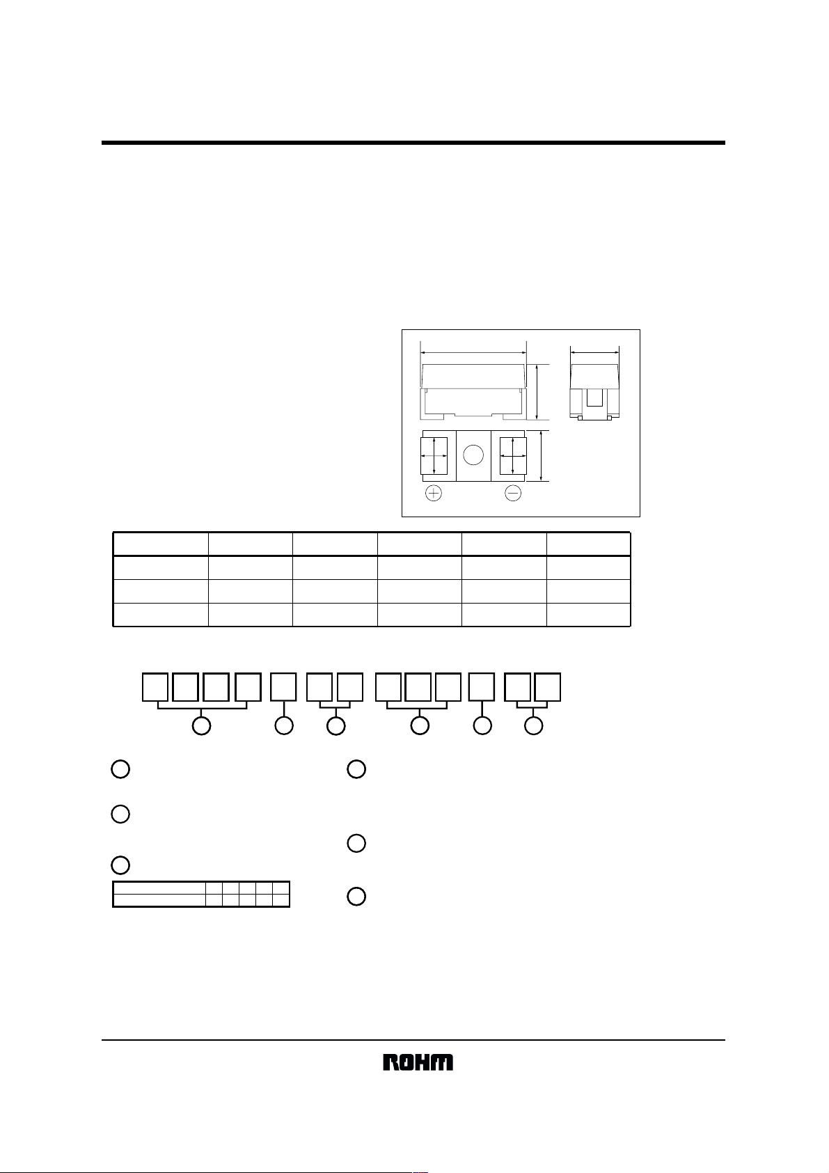
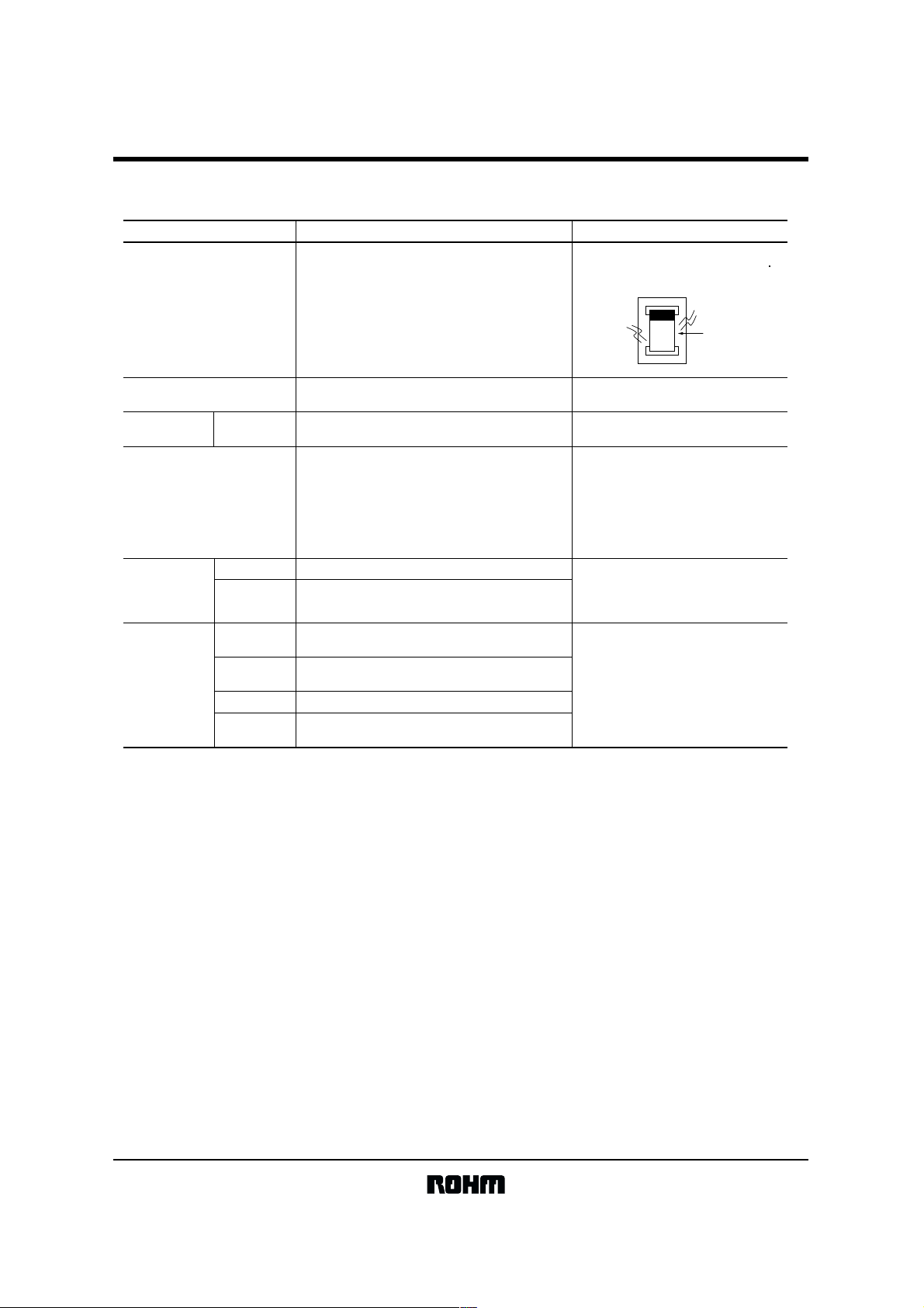
!!!!Features !!!!External dimensions (Units : mm)
1) Safety design by open functiom built - in.
2) Wide capacitance range
3) Screening by thermal shock.
L
H
W
2
S
2
W
S
W
1
Max.
W
1
Case code L W
P (2012) 2.0 0.2 1.25 0.2 0.9 0.2 Max.1.20 0.45 0.3
A (3216) 3.2 0.2 1.6 0.2 1.2 0.2 1.6 0.2 0.8 0.3
B (3528) 3.5 0.2 2.8 0.2 1.9 0.2 1.9 0.2 0.8 0.3
+
−
+
−
+
−
1
+
−
+
−
+
−
W
2
+
−
+
−
+
−
HS
+
−
+
−
T C
11
Series name
TC/TCFG
2
Case code
TC…………M,P,A
TCFG……P,A,B
3
Rated voltage
Rataed voltage
CODE
161
(V)
4
6.30J101A161C20
0G
A0J
2
1D
3
4
5
1
Capacitance
pF Code : 1st two digits represent significant figures, 3rd
digit represent multiplier (number of zeros to follow)
Capacitance Tolerance
M :
±20%
Taping
8: Tape width (8mm)
R:Anode is on the opposite side of the sprocket hole
6
0
4 5
K :
±10%
M 8 R
6
+
−
+
−
+
−
1/15
Page 2
TCFG series
Tantalum capacitors
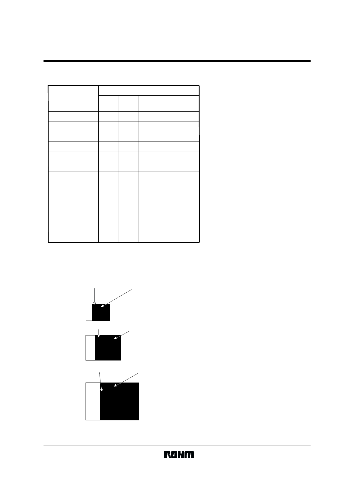
!!!!Capacitance range
TCFG series
Raited voltage (V.DC)
µF
4
0G
6.3
0J
10
1A
16
1C
20
1D
1.0 P,A A
1.5 A
2.2 P,A
3.3 P,A
4.7 P,A P,A P,A,B A,B
6.8 P,A
10 P,A
15 P,A,B P,A,B A,B
22 P,A,B A,B
33 A,B A,B
47 A,B
68
100
∗
Pleasecontactusaboutthisproduct.
typical example
Valtge code
P
P P,A A,B
B
B
P
P
P,A
P,A,B
B
B
B
Capacitance
P
P,A
A,B
A,B
∗
A,B
B
B
A
A,B
A,B
B
B
P case
(2012)
A case
(3216)
B case
(3528)
j J
- -
AA
Valtge code
j 106
YAA
Valtge code
10
16V
YAA
Capacitance
Capacitance
2/15
Page 3
TCFG series
Tantalum capacitors
!!!!Characteristics
Item Performance
Operating temperature −55˚
Max. operating temperature
at rated voltage
Rated voltage (V. DC)
Derated voltage (V. DC)
Surge voltage (V. DC)
Leakage current Less than or equal to the larger of 0.5
Capacitance range 1.0 ~ 100
tan
δ
Impedance
Resistance to
solder heat
Open function
operation
Temperature
cycle
Resistance to
humidity
(steady state)
P case
A case
B case 3.3
Appearance
∆C / C
tan
δ
Appearance
L.C
∆C / C
tan
δ
Appearance
∆C / C
tan
δ
C
~ +125˚
C
+85˚
C
2016106.34
13
106.342.5
26201385.2
0.01CV. Details are given in Table 1,
"Standard Product List".
µ
F
1
µ
F to 4.7µF : 0.08 max.
6.8
µ
F to 15µF : 0.10 max.
1
µ
F max.: 0.04 max.
1.5
µ
F to 22µF : 0.06 max.
33
µ
F to 47µF : 0.08 max.
µ
F to 47µF : 0.06 max.
68
µ
F to 100µF : 0.08 max.
27.5Ω max.P case
20.0Ω max.A case
15.0Ω max.B case
No noticeable irregularities, and the
markings must be easy to read.
Must satisfy the initial specified value.L.C
A B case within ± 5%
P case within ± 10%
P case 1.5 times or less or initial specified tolerance.
A B case must satisfy the initial specified value.
320˚
C
for 20s or less
No noticeable irregularities, and the
markings must be easy to read.
Must satisfy the initial specified value.
P case = Within 150% of initial limit.
P case within ± 10%
A B case within ± 5%
P case 1.5 times or less or initial specified tolerance.
A B case must satisfy the initial specified value.
No noticeable irregularities, and the
markings must be easy to read.
Must satisfy the initial specified value.L.C
P case within ± 20%
A B case within ± 10%
P case 1.5 times or less or initial specified tolerance.
A B case must satisfy the initial specified value.
µ
A or
Test methods / conditions
(based on JIS C 5102, 5143)
at 125˚
C
Measured value 60s after application
of rated voltage.
Measured frequency: 120 ± 12Hz
Measured voltage: 0.5Vrms + 1.5V. DC
Measured circuit: equivalent series
circuit
Measured frequency: 120 ± 12Hz
Measured voltage: 0.5Vrms + 1.5V. DC
Measured circuit: equivalent series
circuit
Measured frequency: 100 ± 10Hz
Measured voltage: 0.5Vrms max.
Measured circuit: equivalent series
circuit
Direct immersion into solder bath
Solder bath temperature: 260 ± 5˚
Immersion time: 5s
Immersion cycles: 1 time
Direct immersion into solder bath
(320 ± 5˚
The four cycles in the table below are
repeated five times in succession.
Measured after being left for 500
± 12hrs. at 60 ± 2˚
RH, then 1 to 2 hrs. at normal room
temperature and humidity.
C
)
Temperature Time
−55 ± 3˚
125 ± 2˚
C
C
C
and 90 to 95%
1
Room temperature
2
3
Room temperature
4
C
30 ± 3mins.
3mins. max.
30 ± 3mins.
3mins. max.
3/15
Page 4
TCFG series
Tantalum capacitors
Temperature
characteristics
Surge
resistance
Hightemperature
load
Terminal
strength
Item Performance
Temperature
∆C / C
tanδ
L.C −
Temperature +85°C
∆C / C
tanδ Must satisfy the initial specified value.
L.C Less than or equal to the larger of 5µA or 0.1CV.
Temperature +125°C
∆C / C
tanδ
L.C Less than or equal to the larger of 6.3µA or
Appearance
∆C / C
tanδ
Appearance No noticeable irregularities, and the
L. C Must satisfy the initial specified value.
∆C / C Within ± 10%
tanδ
Capacitance Value must be stable during measurement.
Appearance No noticeable irregularities.
−55°C
P case within +0% and −15% of the value before testing.
B case within +10% and −0% of the value before testing.
A
P case within 1.5 times of the value before testing.
A B case must satisfy the initial specified value.
P case within +0% and −15% of the value before testing.
B case within +0% and −10% of the value before testing.
A
P case within +20% and −0% of the value before testing.
A B case within +15% and −0% of the value before testing.
P case within 1.5 times of the value before testing.
A B case must satisfy the initial specified value.
0.125CV.
A B case no noticeable irregularities, and the
markings must be easy to read.
Must satisfy the initial specified value.L.C
P case within ± 10%
A B case within ± 5%
P case within 1.5 times of the value before testing.
A B case must satisfy the initial specified value.
markings must be easy to read.
P case within 1.5 times of the value before testing.
A B case must satisfy the initial specified value.
Test methods / conditions
(based on JIS C 5102,5143)
Apply the rated surge voltage for
30 ± 5s at intervals of 5 ± .05mins.
1000 times, with the temperature at
85 ± 2°C.
Temp.
Series Resistance
Applied voltage
Test time
meusure made after pieces shall be left for
1 to 2 hrs under room temp. and room
humidity after test.
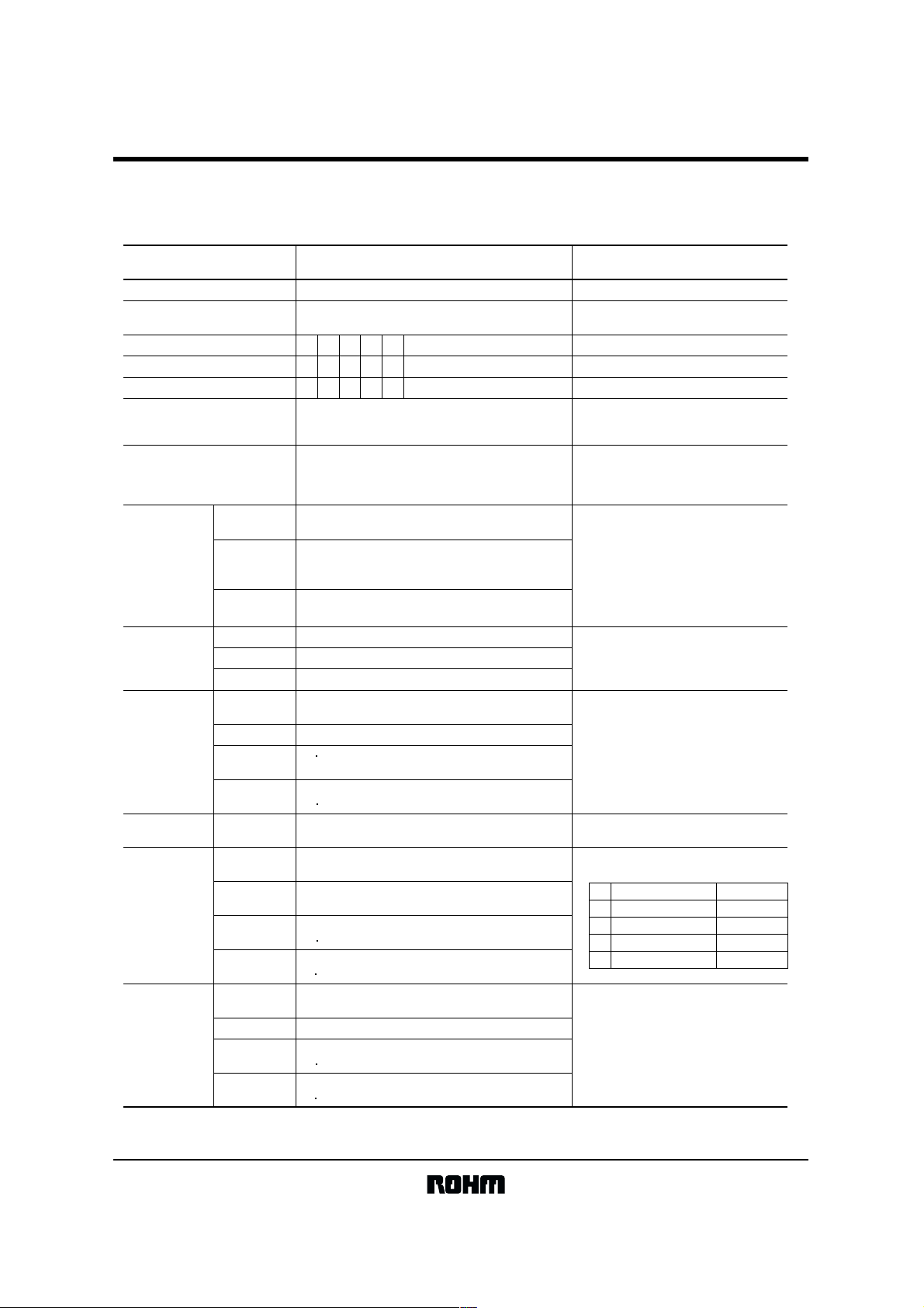
Apply pressure to the device using the
specified tool for 5s so that the center
deflection is 1mm (see below).
: 85 ± 2°C
: 3Ωmax.
: rated voltage
: P case 1000
A B case 2000
20
50
F (Direction of force)
R230
(Units: mm)
1
+36
− 0
hrs
+73
− 0
hrs
45 45
4/15
Page 5
TCFG series
Tantalum capacitors
Item Performance
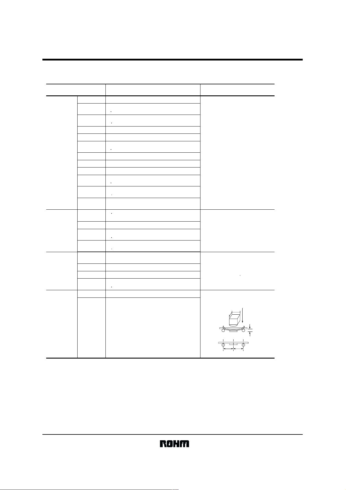
Adhesion Terminals must not detach. With the device mounted on the printed
External dimensions Refer to "External dimensions" Measure using slide calipers that meet
Markings Resistance to
solvents
Solderability
Inspect the solder cover of
the terminals using a solder
immersion test
Marking must be easy to read. Immerse in isopropyl alcohol for
At least 3 / 4 of the surface of the immersed
terminals must be covered with new solder.
circuit board, apply a force of 0.5kg f
from each side for a period of 10 ± 1s.
the requirements of JIS B7507 Class 2.
30 ± 5s.
Immersion speed: 25 ± 2.5mm / s
Pre-processing (accelerated aging):
leave for 1hr over boiling distilled water.
Solder temperature: 235 ± 5°C
Immersion time: 2 ± 0.5s
Solder type: H63A
Flux: rosin 25%, IPA 75%
Test conditions
Device
C105
YAA
Printed circuit board
Force
Resistance to
vibration
polarity
withstanding
voltage
Capacitance
Appearance No noticeable irregularities.
AppearanceReverse
L.C Must be less than or equal to twice the initial
∆C / C Within ± 10% of the value before the test.
tanδ Must be less than or equal to 1.5 times the
Value must be stable during measurement.
No noticeable irregularities, and the markings
must be easy to read.
specified value.
initial specified value.
Vibrate in the X / Y axis at frequencies of
10~55~10Hz / minute for two hours
each, with a total vibration amplitude of
1.5mm.
Apply either 0.1 times the rated voltage,
or 3V, whichever is smaller, via a series
resister of 3Ωmax. and 0.1Ωmin. at a
temperature of 85 ± 2°C.
5/15
Page 6

TCFG series
Tantalum capacitors
!!!!Table 1Standard list, TCFG series
6/15
Page 7

TCFG series
Tantalum capacitors
(P : 2012 A : 3216 B : 3528)
Part No.
TCF GP 0G 225
TCF GP 0G 335
TCF GP 0G 475
TCF GA 0G 475
TCF GP 0G 685
TCF GA 0G 685
TCF GP 0G 106
TCF GA 0G 106
TCF GP 0G 156
TCF GA 0G 156
TCF GB 0G 156
TCF GA 0G 226
TCF GB 0G 226
TCF GA 0G 336
TCF GB 0G 336
TCF GA 0G 476
TCF GB 0G 476
TCF GB 0G 686
TCF GB 0G 107
TCF GP 0J 155
TCF GP 0J 225
TCF GP 0J 335
TCF GA 0J 335
TCF GP 0J 475
TCF GA 0J 475
TCF GP 0J 685
TCF GA 0J 685
TCF GP 0J 106
TCF GA 0J 106
TCF GB 0J 106
TCF GA 0J 156
TCF GB 0J 156
TCF GA 0J 226
TCF GB 0J 226
TCF GA 0J 336
TCF GB 0J 336
TCF GB 0J 476
TCF GB 0J 686
Rated
voltage
at 85°C
Tolerance
(M : ±20%, K : ±10%)
Derated
voltage
at 125°C
(V)
4 2.5 5.2 2.2 ±20,10 0.5 8 P
4 2.5 5.2 3.3 ±20,10 0.5 8
4 2.5 5.2 4.7 ±20,10 0.5
4 2.5 5.2
4 2.5 5.2
4 2.5 5.2
4 2.5 5.2
4 2.5 5.2
4 2.5 5.2
4 2.5 5.2
4
4
4
4
4
4
4
4
4
6.3 4 8 1.5
6.3 4 8 2.2
6.3 4 8 3.3
6.3 4 8
6.3 4 8
6.3 4 8
6.3 4 8
6.3 4 8
6.3 4 8
6.3 4 8
6.3
6.3
6.3
6.3
6.3
6.3
6.3
6.3
6.3
(V)
2.5 5.2
2.5 5.2
2.5 5.2
2.5 5.2
2.5 5.2
2.5 5.2
2.5 5.2
2.5 5.2
2.5 5.2
Surge
voltage
at 85°C
48
48
48
48
48
48
48
48
48
Capacitance
(V)
Leakage
Tolerance
(µF)
4.7 0.5
6.8
6.8 0.5
10
10 0.5
15
15
15 0.6
22
22
33
33 1.3
47
47 1.9
68 2.7
100 4.0
3.3 0.5
4.7
4.7 0.5
6.8
6.8 0.5
10
10 0.6
10 0.6
15
15 0.9
22 1.4
22
33 2.1
33
47 3.0
68 4.3
(%)
±20,10
±20,10
±20,10
±20,10
±20,10
±20,10
±20,10
±20,10
±20,10
±20,10
±20,10
±20,10
±20,10
±20,10 6
±20,10 8
±20,10
±20,10
±20,10
±20,10
±20,10
±20,10
±20,10
±20,10
±20,10
±20,10
±20,10
±20,10
±20,10
±20,10
±20,10
±20,10
±20,10
±20,10
±20,10
±20,10
current
at 25°C
1WV.60s
(µA)
0.5
0.5
0.6
0.6
0.9
0.9
1.3
1.9
0.5
0.5
0.5
0.5
0.5
0.6
0.9
1.4
2.1
DF
120Hz
25°C
(%)
8
6
10
6
10
6
10
6
6
6
6
8
6
8
8
8
8
8
6
8
6
10
6
10
6
6
6
6
6
6
8
6
6
8
Case
code
P
P
A
P
A
P
A
P
A
B
A
B
A
B
A
B
B
B
P
P
P
A
P
A
P
A
P
A
B
A
B
A
B
A
B
B
B
7/15
Page 8

TCFG series
Tantalum capacitors
(P : 2012 A : 3216 B : 3528)
Case
code
P
A
P
A
P
A
P
A
B
A
B
A
B
A
B
B
B
B
P
A
A
A
A
B
A
B
A
B
B
B
B
A
Part No.
TCF GP 1A 105
TCF GP 1A 155
TCF GA 1A 155
TCF GP 1A 255
TCF GA 1A 225
TCF GP 1A 335
TCF GA 1A 335
TCF GP 1A 475
TCF GA 1A 475
TCF GB 1A 475
TCF GB 1A 685
TCF GB 1A 106
TCF GA 1A 156
TCF GB 1A 156
TCF GB 1A 226
TCF GB 1A 336
TCF GB 1A 476
TCF GP 1C 105
TCF GA 1C 105
TCF GA 1C 155
TCF GA 1C 225
TCF GA 1C 335
TCF GB 1C 335
TCF GA 1C 475
TCF GB 1C 475
TCF GA 1C 685
TCF GB 1C 685
TCF GB 1C 106
TCF GB 1C 156
TCF GB 1C 226
TCF GA 1D 105
Rated
voltage
at 85°C
Tolerance
(M : ±20%, K : ±10%)
Derated
voltage
at 125°C
(V)
10 6.3 13 1.0
10 6.3 13
10 6.3 13
10 6.3 13
10 6.3 13
10 6.3 13
10 6.3 13
10 6.3 13
10
10 6.3
10
10
10
10
10
10
10
10
10
16 1.0
16
16
16
16
16
16
16
16
16
16
16
16 10
20 13 26 1.0
(V)
6.3 13
6.3
6.3
6.3
6.3
6.3
6.3
6.3
6.3
6.3
10
10
10
10
10
10
10
10
10
10
10
10
Surge
voltage
at 85°C
(V)
13
13
13
13
13
13
13
13
13
13
20
20
20
20
20
20
20
20
20
20
20
20
20
Capacitance
(µF)
1.5
1.5
2.2
2.2
3.3
3.3
4.7
4.7
4.7
6.8TCF GA 1A 685
6.8
10TCF GA 1A 106
10
15
15
22
33
47
1.0
1.5
2.2
3.3
3.3
4.7
4.7
6.8
6.8
10
15
22
Leakage
Tolerance
(%)
±20,10 0.5 8 P
±20,10 0.5 8
±20,10 0.5
±20,10
±20,10
±20,10
±20,10
±20,10
±20,10
±20,10
±20,10
±20,10
±20,10
±20,10
±20,10
±20,10
±20,10 6
±20,10 6
±20,10
±20,10
±20,10
±20,10
±20,10
±20,10
±20,10
±20,10
±20,10
±20,10
±20,10
±20,10
±20,10
±20,10
±20,10
current
at 25°C
1WV.60s
(µA)
0.5
0.5
0.5
0.5
0.5
0.5
0.5
0.7
0.7
1.0
1.0
1.5
1.5
2.2
3.3
4.7
0.5
0.5
0.5
0.5
0.5
0.5
0.8
0.8
1.1
1.1
1.6
2.4
3.5
0.5
DF
120Hz
25°C
(%)
6
8
6
8
6
8
6
6
6
6
6
6
6
6
6
8
4
6
6
6
6
6
6
6
6
6
6
6
4
8/15
Page 9
TCFG series
Tantalum capacitors
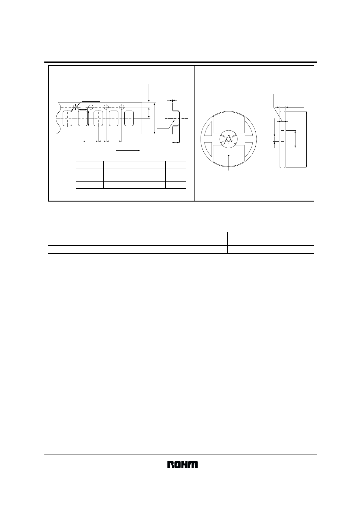
Taping Reel
TCFG Plastic reel
+ 0.1
φ1.5
− 0
A
4.0 ± 0.1B4.0 ± 0.1
2.0 ± 0.05
Pull-out direction
Case code A ± 0.1 B ± 0.1 t1 ± 0.05 t2 ± 0.1
P (2012) 1.55 2.3 0.25 1.5
A (3216) 1.9 3.5 0.25 1.9
B (3528) 3.3 3.8 0.25 2.2
Some emboss tapes have the center hole
on its bottom.
1.75 ± 0.1
3.5 ± 0.05
8.0 ± 0.3
Product
!!!!Packaging style
Part No. Package type Packaging style
TCFG
Taping Plastic taping φ180 mm reel
t
1
11.4 ± 1.0
9.0 ± 0.3
φ13 ± 0.2
t
2
Label position
EIAJ ETX - 7001comformed
0
0
− 3
+ 1
φ60
φ180
Symbol
R 2,000
Basic ordering unit (pcs)
9/15
Page 10

TCFG series
Tantalum capacitors
!!!! Electrical characteristics and operation notes
(1) Soldering conditions (soldering temperature and soldering time)
Reflow
TCFG
170
Preheat
280
TCFG
160
(°C)
150
TEMPERATURE
140
130
0 60 90 120 150 180
(sec)
TIME
Fig.1 Reflow (Infrared Ray, Hot Plate, Hot Air)
270
260
250
(°C)
240
230
220
TEMPERATURE
210
200
0 2 4 6 8 10 12 14 16
TIME
(sec)
Fig.2 Flow
(Dipping wave soldering)
TCFG
260
(°C)
240
TEMPERATURE
220
200
0 10203040506070
TIME
(sec)
340
320
(°C)
300
TEMPERATURE
280
0 5 10 15 20 25
TIME (
sec)
Fig.3 Hand soldering
(soldering gun output:
30W or less)
TCFG
(2) Leakage current-to-voltage ratio
1
0.1
LEALKAGE CURRENT RATIO DCL / DCL
0.01
0 20 40 60 80 100
% OF RATED VOLTAGE (
Fig.4
VR)
10/15
Page 11

TCFG series
Tantalum capacitors
(3) Derating voltage as function of temperature
100
)
R
90
(V
80
70
60
PERCENT OF 85°C RVDC1
50
75 85 95 105 115 125
TEMPERATURE
(°C)
Fig.5
(4) Reliability
The malfunction rate of tantalum solid state electrolytic capacitors varies considerably depending on the conditions of
usage (ambient temperature, applied voltage, circuit resistance).
Formula for calculating malfunction rate
λp = λb × (π
E × πSR × πQ × πCV)
λp
: Malfunction rate stemming from operation
λb
: Basic malfunction rate
π
E : Environmental factors
π
SR : Series resistance
π
Q : Level of malfunction rate
π
CV : Capacitance
For details on how to calculate the malfunction rate stemming from operation, see the tantalum solid state electrolytic
capacitors column in MIL-HDBK-217.
Malfunction rate as function of operating Malfunction rate as function of circuit resistance (Ω/V)
temperature and rated voltage
1.0
0.5
0.3
0.2
0.1
0.06
0.03
0.02
FAILURE RATE COEFFICIENT
0.01
Applied Voltage
Ratio =
Rated Voltage
20 40 60 85
OPERATING TEMPERATURE
1.0
0.7
0.5
0.3
0.1
(°C)
Fig.6
85°C
Rated Voltage
(V.DC) (V.DC) (V.DC) (V.DC)
4
6.3
10
16
20
Surge Voltage
Category Voltage Surge Voltage
5.2
8
13
20
26
6.0
4.0
(π)
2.0
1.0
0.8
0.6
RESISTANCE COEFFICIENT
0.4
0.1 0.2 0.60.4 3.01.0 2.0
RESISTANCE OF CIRCUIT
Fig.7
2.5
6.3
10
13
125°C
3.4
4
5
9
12
16
(Ω / V)
11/15
Page 12

TCFG series
Tantalum capacitors
(5) External temperature vs. fuse blowout (6) Power vs. fuse blowout characteristics / Product sur face temperature
360
350
340
330
320
310
300
290
280
EXTERNAL TEMPERATURE (°C)
270
260
1 10 100
TIME
No failed
(sec)
Fig.8
P case (2012)
A case (3216)
B case (3528)
Failed
Half failed
Note: Solder the chip at 300°C or less. If it is soldered using
a temperature higher than 300°C, open function built-in may operate.
(7) Maximum power dissipation
Warming of the capacitor due to ripple voltage balances with warming caused by Joule heating and by radiated heat.
Maximum allowable warming of the capacitor is to 5°C above ambient temperature. When warming exceeds 5°C, it can
damage the dielectric and cause a short circuit.
Power dissipation (P) = I
2
$ R
Ripple current
P : As shown in table at right
R : Equivalent series resistance
Notes:
1. Please be aware that when case size is changed, maximum allowable power dissipation is reduced.
2. Maximum power dissipation varies depending on the package. Be sure to use a case which will keep warming within
the limits shown in the table below.
Allowable power dissipation (W) and maximum temperature rising
100
90
80
70
(sec)
60
50
40
30
OPERATING TIME
20
10
0
024
No operating area
P case (2012)
A case (3216)
B case (3528)
Open-function charcteristic
Surface temp.
curve of the products
Operating area
681097531
ELECTRIC POWER
Fig.9
300
250
200
150
SURFACE TEMP. OF THE PRODUCT (°C)
(W)
Case
Ambient
temp.
+25°C +55°C +85°C +125°C
0.025P case (2012) 0.022 0.020 0.010
0.070A case (3216) 0.063 0.056 0.028
0.080B case (3528) 0.072 0.064 0.032
5Max. temp. rise 5 5 2
12/15
Page 13

TCFG series
Tantalum capacitors
(8) Impedance frequency characteristics (9) ESR frequency characteristics
100000
10000
1000
(Ω)
100
10
IMPEDANCE
1
1 100 10k 1M 500M100M
FREQUENCY
Fig.10
(10) Temperature characteristics
10
6
(%)
2
0
−2
CAP CHANGE
−6
CAP 120Hz
10V−1µF P case (2012)
4V−4.7µF A case (3216)
4V−33µF B case (3528)
A105
P case (2012)
G475
A case (3216)
C105
A case (3216)
C335
B case (3528)
(Hz)
100
10
(Ω)
ESR
1
0.1
1 100 10k 1M 500M100M
FREQUENCY
A105
P case (2012)
G475
A case (3216)
C105
A case (3216)
C335
B case (3528)
(Hz)
Fig.11
DF 120Hz
10V−1µF P case (2012)
4V−4.7µF A case (3216)
4V−33µF B case (3528)
DF (%)
5
4
3
2
1
−10
−55 25
TEMPERATURE
Fig.12
85 125
(°C)
0
−55 25
TEMPERATURE (°C)
Fig.13
85 125
1000
100
(nA)
LC
10
0
−55 25
LC 1WV
10V−1µF P case (2012)
4V−4.7µF A case (3216)
4V−33µF B case (3528)
TEMPERATURE
Fig.14
85 125
(°C)
13/15
Page 14

TCFG series
Tantalum capacitors
Inrush current
Beware of inrush current.
Inrush currents are inversely proportional to ESR. Large inrush currents can cause component failure.
100
10
1
INRUSH CURRENT (A)
0.1
0.1 1 10 100
33µF
33µF
15µF
4.7µF
Vpp = 10V limit = 20A
Pulse Width = 500µsec.
Power OP Amp Slew Rate = 10V / 6µs
Tantalum capacitor
Aluminum electrolyte
100µF
4.7µF
47µF
22µF
ESRΩ (100kHz)
Fig.16 Maximum inrush current and ESR
Inrush current can be limited by means of a protective resistor.
100
10
I (A)
V
I =
0.476
R
C
1
I =
0.476 + R
V
SAMPLE 16V-3.3µF NEC
Pulse width = 500µsec
Slew rate = 10V-6µc
R = 0Ω
Current limit = 20A
0.25
0.5
1.0
2.0
5.0
0.1
0.1 1 10 100
Fig.17 Imax change due to protective resistor R
V (V)
(11) Ultrasonic cleaning
Carry out cleaning under the mildest conditions possible. The internal element of a tantalum capacitor are larger than
those of a transistor or diode, so it is not as resistant to ultrasonic waves.
Example : water
Propagation speed 1500m / s
Solvent density 1g / cm
Frequency and wavelength
Frequency Wavelength
20kHz 7.5cm
28kHz 5.3cm
50kHz 3.0cm
3
Precautions
14/15
Page 15

TCFG series
Tantalum capacitors
1) Do not allow solvent to come to a boil (kinetic energy increases).
$ Ultrasonic output 0.5W / cm
$ Use a solvent with a high boiling point.
$ Lower solvent temperature.
2) Ultrasonic cleaning frequency
28 kHz or less
3) Keep cleaning time as short as possible.
4) Move item being cleaned.
Standing waves caused by the ultrasonic waves can cause stress to build up in part of the item being cleaned.
Reference
Kinetic energy = 2 x π x frequency x
2
or less
2 x ultrasonic output
propagation speed x solvent density
15/15
Page 16

Appendix
No technical content pages of this document may be reproduced in any form or transmitted by any
means without prior permission of ROHM CO.,LTD.
The contents described herein are subject to change without notice. The specifications for the
product described in this document are for reference only. Upon actual use, therefore, please request
that specifications to be separately delivered.
Application circuit diagrams and circuit constants contained herein are shown as examples of standard
use and operation. Please pay careful attention to the peripheral conditions when designing circuits
and deciding upon circuit constants in the set.
Any data, including, but not limited to application circuit diagrams information, described herein
are intended only as illustrations of such devices and not as the specifications for such devices. ROHM
CO.,LTD. disclaims any warranty that any use of such devices shall be free from infringement of any
third party's intellectual property rights or other proprietary rights, and further, assumes no liability of
whatsoever nature in the event of any such infringement, or arising from or connected with or related
to the use of such devices.
Upon the sale of any such devices, other than for buyer's right to use such devices itself, resell or
otherwise dispose of the same, no express or implied right or license to practice or commercially
exploit any intellectual property rights or other proprietary rights owned or controlled by
ROHM CO., LTD. is granted to any such buyer.
Products listed in this document use silicon as a basic material.
Products listed in this document are no antiradiation design.
Notes
The products listed in this document are designed to be used with ordinary electronic equipment or devices
(such as audio visual equipment, office-automation equipment, communications devices, electrical
appliances and electronic toys).
Should you intend to use these products with equipment or devices which require an extremely high level of
reliability and the malfunction of with would directly endanger human life (such as medical instruments,
transportation equipment, aerospace machinery, nuclear-reactor controllers, fuel controllers and other
safety devices), please be sure to consult with our sales representative in advance.
About Export Control Order in Japan
Products described herein are the objects of controlled goods in Annex 1 (Item 16) of Export Trade Control
Order in Japan.
In case of export from Japan, please confirm if it applies to "objective" criteria or an "informed" (by MITI clause)
on the basis of "catch all controls for Non-Proliferation of Weapons of Mass Destruction.
Appendix1-Rev1.0
 Loading...