

Page 1
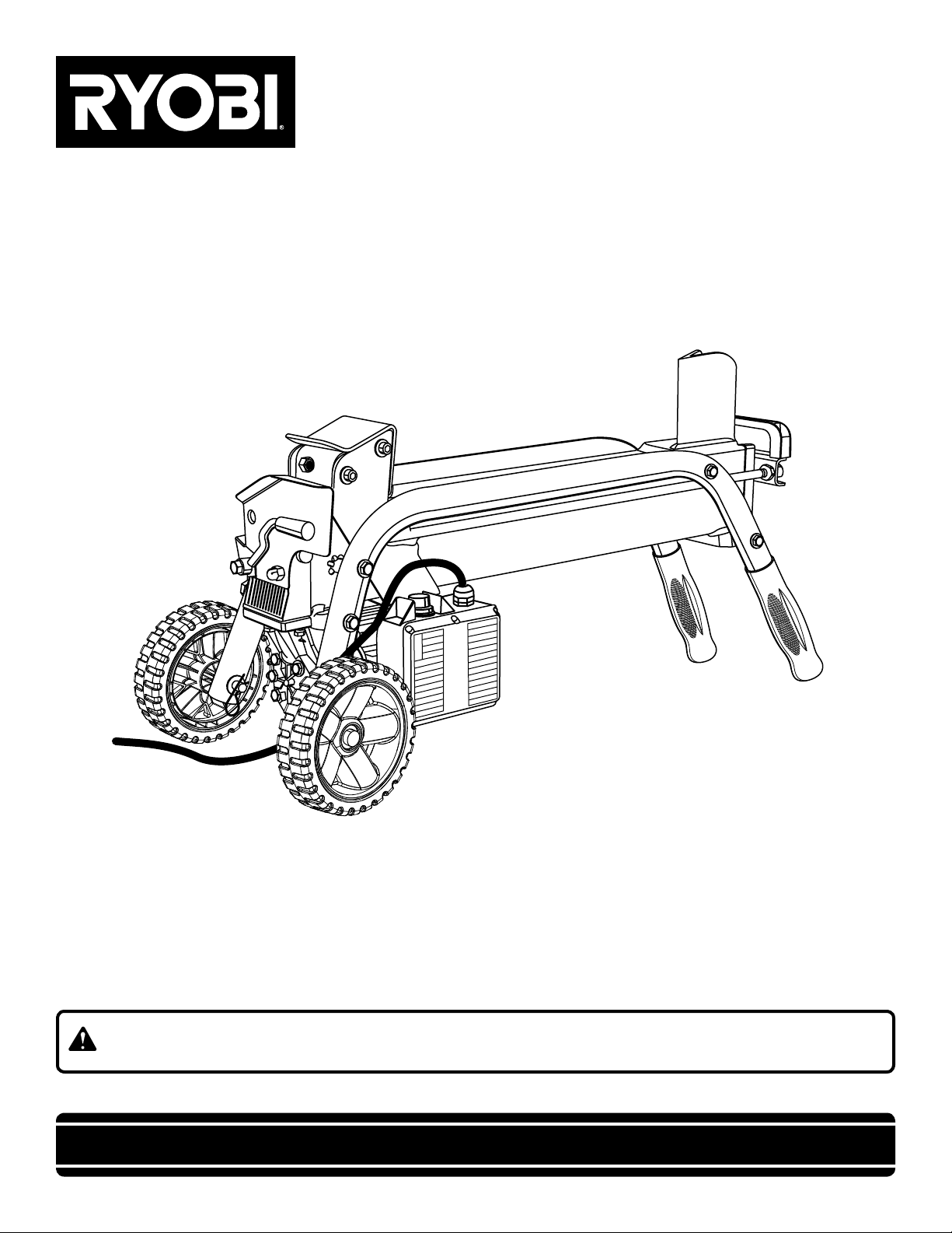
OPERATOR’S MANUAL
ELECTRIC LOG SPLITTER
RY49701
Your Log Splitter has been engineered and manufactured to Ryobi’s high standard for dependability, ease of operation, and
operator safety. When properly cared for, it will give you years of rugged, trouble-free performance.
WARNING: To reduce the risk of injury, the user must read and understand the operator's manual before using
this product.
Thank you for buying a Ryobi product.
SAVE THIS MANUAL FOR FUTURE REFERENCE
Page 2

TABLE OF CONTENTS
n Introduction ...................................................................................................................................................................... 2
�n General Safety Rules.....................................................................................................................................................3-4
�n Specific Safety Rules........................................................................................................................................................4
��n Symbols.........................................................................................................................................................................5-6
��n Electrical........................................................................................................................................................................... 7
��n Features............................................................................................................................................................................ 8
��n Assembly.......................................................................................................................................................................... 9
�n Operation...................................................................................................................................................................10-12
�n Maintenance................................................................................................................................................................... 13
n Troubleshooting .............................................................................................................................................................. 14
�n Parts Ordering / Service................................................................................................................................................. 16
INTRODUCTION
This tool has many features for making its use more pleasant and enjoyable. Safety, performance, and dependability have
been given top priority in the design of this product making it easy to maintain and operate.
2
Page 3

GENERAL SAFETY RULES
WARNING:
Read and understand all instructions. Failure to follow
all instructions listed below, may result in electric shock,
fire and/or serious personal injury.
READ ALL INSTRUCTIONS
n KNOW YOUR POWER TOOL. Read the operator’s
manual carefully. Learn the applications and limitations as
well as the specific potential hazards related to this tool.
n G UARD AGA INST EL E CTRI C AL SHOC K BY
PREVENTING BODY CONTACT WITH GROUNDED
SURFACES. For example: pipes, radiators, ranges,
refrigerator enclosures.
n KEEP GUARDS IN PLACE and in good working order.
n REMOVE ADJUSTING KEYS AND WRENCHES. Form
habit of checking to see that keys and adjusting wrenches
are removed from tool before turning it on.
n KEEP WORK AREA CLEAN. Cluttered areas and benches
invite accidents. DO NOT leave tools or pieces of wood
on the tool while it is in operation.
n DO NOT USE IN DANGEROUS ENVIRONMENTS. Do
not use power tools in damp or wet locations or expose
to rain. Keep the work area well lit.
n KEEP CHILDREN AND VISITORS AWAY. All visi-
tors should wear safety glasses and be kept a safe
distance from work area. Do not let visitors contact
tool or extension cord while operating.
n MAKE WORKSHOP CHILDPROOF with padlocks,
master switches, or by removing starter keys.
n DON’T FORCE THE TOOL. It will do the job better and
safer at the feed rate for which it was designed.
n USE THE RIGHT TOOL. Do not force the tool or attach-
ment to do a job for which it was not designed.
n USE THE PROPER EXTENSION CORD. Make sure your
extension cord is in good condition. Use only a cord heavy
enough to carry the current your product will draw. An
undersized cord will cause a drop in line voltage resulting in
loss of power and overheating. A wire gauge size (A.W.G.)
of at least 14 is recommended for an extension cord 25
feet or less in length. If in doubt, use the next heavier
gauge. The smaller the gauge number, the heavier the cord.
n DRESS PROPERLY. Do not wear loose clothing, neckties,
or jewelry that can get caught and draw you into moving
parts. Rubber gloves and nonskid footwear are recommended when working outdoors. Also wear protective
hair covering to contain long hair.
n ALWAYS WE AR SAF ETY GLASSES WITH SIDE
SHIELDS. Everyday eyeglasses have only impact-
resistant lenses, they are NOT safety glasses.
n SECURE WORK. Use clamps or a vise to hold work
when practical, it is safer than using your hand and
frees both hands to operate the tool.
n DO NOT OVERREACH. Keep proper footing and
balance at all times.
n MAINTAIN TOOLS WITH CARE. Keep tools sharp
and clean for better and safer performance. Follow instructions for lubricating and changing accessories.
n DISCONNECT TOOLS. When not in use, before servic-
ing, or when changing attachments, blades, bits, cutters,
etc., all tools should be disconnected from power source.
n AVOID ACCIDENTAL STARTING. Be sure switch is off
when plugging in any tool.
n USE RECOMMENDED ACCESSORIES. Consult the
operator’s manual for recommended accessories. The
use of improper accessories may result in injury.
n NEVER STAND ON TOOL. Serious injury could occur if
the tool is tipped.
n CHECK DAMAGED PARTS. Before further use of the
tool, a guard or other part that is damaged should be
carefully checked to determine that it will operate properly
and perform its intended function. Check for alignment
of moving parts, binding of moving parts, breakage of
parts, mounting and any other conditions that may affect
its operation. A guard or other part that is damaged must
be properly repaired or replaced by an authorized service
center to avoid risk of personal injury.
n USE THE RIGHT DIRECTION OF FEED. Feed work into
a blade, cutter, or sanding spindle against the direction
or rotation of the blade, cutter, or sanding spindle only.
n NEVER LEAVE TOOL RUNNING UNATTENDED. TURN
THE POWER OFF. Don't leave tool until it comes to a
complete stop.
n PROTECT YOUR LUNGS. Wear a face or dust mask if
the cutting operation is dusty.
n PROTECT YOUR HEARING. Wear hearing protection
during extended periods of operation.
n DO NOT ABUSE CORD. Never carry tool by the cord or
yank it to disconnect from receptacle. Keep cord from
heat, oil, and sharp edges.
n USE OUTDOOR EXTENSION CORDS. When tool
is used outdoors, use only extension cords with
approved ground connection that are intended for use
outdoors and so marked.
n NEVER USE IN AN EXPLOSIVE ATMOSPHERE.
Normal sparking of the motor could ignite fumes.
n INSPECT TOOL CORDS PERIODICALLY. If dam-
aged, have repaired by a qualified service technician at
an authorized service facility. The conductor with insulation
having an outer surface that is green with or without yellow
stripes is the equipment-grounding conductor. If repair
or replacement of the electric cord or plug is necessary,
do not connect the equipment-grounding conductor to a
live terminal. Repair or replace a damaged or worn cord
immediately. Stay constantly aware of cord location and
keep it well away from the rotating blade.
n INSPECT EXTENSION CORDS PERIODICALLY and
replace if damaged.
n KEEP TOOL DRY, CLEAN, AND FREE FROM OIL AND
GREASE. Always use a clean cloth when cleaning. Never
use brake fluids, gasoline, petroleum-based products, or
any solvents to clean tool.
n STAY ALERT AND EXERCISE CONTROL. Watch what
you are doing and use common sense. Do not operate
tool when you are tired. Do not rush.
3
Page 4

GENERAL SAFETY RULES
n DO NOT USE TOOL IF SWITCH DOES NOT TURN IT
ON AND OFF. Have defective switches replaced by an
authorized service center.
n DO NOT OPERATE A TOOL WHILE UNDER THE
INF LUENC E O F DR UGS, ALCO HOL, OR ANY
MEDICATION.
n ALWAYS carry the tool only by the carrying handle.
n USE ONLY RECOMMENDED ACCESSORIES listed
in this manual or addendums. Use of accessories that
are not listed may cause the risk of personal injury.
Instructions for safe use of accessories are included
with the accessory.
n TOOL SERVICE MUST BE PERFORMED ONLY BY
QUALIFIED REPAIR PERSONNEL. Service or mainte-
nance performed by unqualified personal could result in
a risk of injury.
SPECIFIC SAFETY RULES
n DO NOT ALLOW anyone to operate the log splitter who
has not read the operator’s manual or has not been
instructed on the safe use of the splitter.
n NEVER ALLOW CHILDREN OR UNTRAINED ADULTS
TO OPERATE THIS MACHINE.
n IF SOMEONE is helping load logs to be split, DO NOT
start the machine until that person is clear of the area.
n NEV ER ALL OW ANY ONE TO RIDE O N THE
MACHINE
n �NEVER TRANSPORT ANYTHING OR ANYONE ON THE
LOG SPLITTER.
n �HIGH FLUID PRESSURES ARE DEVELOPED IN HY-
DRAULIC LOG SPLITTERS. Pressurized hydraulic fluid
escaping through a pin hole opening can puncture skin
and cause severe blood poisoning. Heed the following
instructions at all times:
a) Do not operate the machine with frayed, kinked,
cracked, or damaged hoses, fittings, or tubing.
b) Stop the engine and relieve hydraulic system pressure
before changing or adjusting fittings, hoses, tubing,
or other system components.
c) Do not adjust the pressure settings of the pump or value.
d) Never use your hand. Leaks can be located by
passing cardboard or wood over the suspected area.
Look for discoloration. If injured by escaping fluid,
see a doctor at once. Serious infection or reaction can
develop if proper medical treatment is not adminis-
tered immediately.
n KEEP THE OPERATOR ZONE and adjacent area clear
for safe, secure footing.
n
LOG SPLITTERS SHOULD BE USED ONLY for splitting
wood. DO NOT use for other purposes unless the manu-
facturer provides attachments and instructions.
n MAKE SURE THE LOG SPLITTER is on a level surface.
Block the splitter as required to prevent unintended move-
ment.
n ALWAYS OPERATE the splitter from the manufacturer’s
indicated operator zone.
.
n WHEN SERVICING use only identical replacement parts.
Use of any other parts may create a hazard or cause
product damage.
n ALWAYS STAY ALERT! Do not allow familiarity (gained
from frequent use of your tool) to cause a careless mistake. ALWAYS REMEMBER that a careless fraction of
a second is sufficient to inflict severe injury.
n MAKE SURE THE WORK AREA HAS AMPLE LIGHTING
to see the work and that no obstructions will interfere with
safe operation BEFORE performing any work using your
tool.
n ALWAYS TURN OFF THE TOOL before disconnecting it
to avoid accidental starting when reconnecting to power
supply. NEVER leave the tool unattended while connected
to a power source.
n LOGS TO BE SPLIT ON RAM-TYPE UNITS should be
cut as squarely as possible.
n THE MACHINE OWNER should instruct anyone assisting
him or her in safe log splitting operation.
n ALWAYS operate the log splitter with all safety equip-
ment in place and all controls properly adjusted for safe
operation.
n ALWAYS operate the log splitter at manufacturer’s rec-
ommended speed.
n WHEN LOADING a ram-type log splitter, place your
hands on the sides of the log not at the ends. NEVER
place your hands or any part of your body between a log
and any part of the log splitter.
n ON RAM-TYPE log splitters, NEVER attempt to split
more than one (1) log at a time unless the ram has been
fully extended and a second log is needed to complete
the separation of the first log.
n �ON RAM-TYPE log splitters on which the logs are not
square, the longest portion of the log should be rotated
down and the most square end placed against the ram.
n CLEAR DEBRIS from moving parts but only when the
power source is shut off.
n USE ONLY YOUR HAND TO OPERATE THE LOG
SPLITTER CONTROLS.
n ALWAYS UNPLUG FROM THE POWER SOURCE while
repairing or adjusting the splitter except as recommended
by the manufacturer.
n CIRCUIT CAPACITY AND FUSES:
a) Use only an electrical circuit having adequate capacity
as recommended by the log splitter manufacturer.
b) “Blowing” a fuse or tripping a circuit breaker is usually
a warning that you are overloading the machine or
have too many devices taking power from the circuit,
or both. Do not install a higher capacity fuse!
n LEARN AND UNDERSTAND all controls and the proper
use of the equipment.
n SAVE T HESE I NSTRU CTION S. Ref e r to t hem
frequently and use to instruct other users. If you loan
someone this tool, loan them these instructions also.
4
Page 5

SYMBOLS
10' 3m
Some of the following symbols may be used on this tool. Please study them and learn their meaning. Proper interpretation of these symbols will allow you to operate the tool better and safer.
SYMBOL NAME DESIGNATION/EXPLANATION
V Volts
A Amperes
Hz Hertz
W Watt
min Minutes
Alternating Current
Direct Current
n
o
.../min
No Load Speed
Class II Construction
Per Minute
Wet Conditions Alert
Voltage
Current
Frequency (cycles per second)
Power
Time
Type of current
Type or a characteristic of current
Rotational speed, at no load
Double-insulated construction
Revolutions, strokes, surface speed, orbits etc., per minute
Do not expose to rain or use in damp locations.
Read The Operator’s Manual
Eye Protection
Safety Alert
Wear Gloves
Wear Safety Footwear
Keep Hands Away Always keep hands away from the wedge and the ram.
To reduce the risk of injury, user must read and understand
operator’s manual before using this product.
Always wear safety goggles or safety glasses with side shields
and a full face shield when operating this product.
Precautions that involve your safety.
Always wear nonslip, heavy-duty protective gloves when
operating this product.
Always wear nonslip safety footwear when operating this product.
Always keep bystanders at least 10 ft. (3 m) away.Keep Bystanders Away
5
Page 6

SYMBOLS
The following signal words and meanings are intended to explain the levels of risk associated with this product.
SYMBOL SIGNAL MEANING
DANGER: Indicates an imminently hazardous situation, which, if not avoided, will
result in death or serious injury.
WARNING: Indicates a potentially hazardous situation, which, if not avoided, could
result in death or serious injury.
CAUTION: Indicates a potentially hazardous situation, which, if not avoided, may
result in minor or moderate injury.
CAUTION: (Without Safety Alert Symbol) Indicates a situation that may result in
property damage.
SERVICE
Servicing requires extreme care and knowledge and should
be performed only by a qualified service technician. For
service we suggest you return the product to your nearest
AUTHORIZED SERVICE CENTER for repair. When servicing, use only identical replacement parts.
WARNING:
To avoid serious personal injury, do not attempt to use
this product until you read thoroughly and understand
completely the operator’s manual. Save this operator’s
manual and review frequently for continuing safe operation and instructing others who may use this product.
WARNING:
The operation of any power tool can result in foreign objects being thrown into your eyes, which can
result in severe eye damage. Before beginning power tool operation, always wear safety goggles or
safety glasses with side shields and a full face shield when needed. We recommend Wide Vision Safety
Mask for use over eyeglasses or standard safety glasses with side shields. Always use eye protection
which is marked to comply with ANSI Z87.1.
SAVE THESE INSTRUCTIONS
6
Page 7

ELECTRICAL
EXTENSION CORDS
Use only 3-wire extension cords that have 3-prong grounding plugs and 3-pole receptacles that accept the tool's plug.
When using a power tool at a considerable distance from the
power source, use an extension cord heavy enough to carry
the current that the tool will draw. An undersized extension
cord will cause a drop in line voltage, resulting in a loss of
power and causing the motor to overheat. Use the chart
provided below to determine the minimum wire size required
in an extension cord. Only round jacketed cords listed by
Underwriter's Laboratories (UL) should be used.
**Ampere rating (on tool faceplate)
0-2.0 2.1-3.4 3.5-5.0 5.1-7.0 7.1-12.0 12.1-16.0
Cord Length Wire Size (A.W.G.)
25' 16 16 16 16 14 14
50' 16 16 16 14 14 12
100' 16 16 14 12 10 —
**Used on 12 gauge - 20 amp circuit.
NOTE: AWG = American Wire Gauge
When working with the tool outdoors, use an extension cord
that is designed for outside use. This is indicated by the
letters "WA" on the cord's jacket.
Before using an extension cord, inspect it for loose or
exposed wires and cut or worn insulation.
WARNING:
Keep the extension cord clear of the working area.
Position the cord so that it will not get caught on lumber,
tools or other obstructions while you are working with a
power tool. Failure to do so can result in serious personal
injury.
SPEED AND WIRING
The speed is not constant and decreases under a load
or with lower voltage. For voltage, the wiring in a shop
is as important as the motor’s horsepower rating. A line
intended only for lights cannot properly carry a power
tool motor. Wire that is heavy enough for a short distance
will be too light for a greater distance. A line that can
support one power tool may not be able to support two
or three tools.
GROUNDING INSTRUCTIONS
In the event of a malfunction or breakdown, grounding
provides a path of least resistance for electric current to
reduce the risk of electric shock. This tool is equipped with
an electric cord having an equipment-grounding conductor and a grounding plug. The plug must be plugged into a
matching outlet that is properly installed and grounded in
accordance with all local codes and ordinances.
Do not modify the plug provided. If it will not fit the outlet,
have the proper outlet installed by a qualified electrician.
Improper connection of the equipment-grounding conductor
can result in a risk of electric shock. The conductor with
insulation having an outer surface that is green with or without yellow stripes is the equipment-grounding conductor. If
repair or replacement of the electric cord or plug is necessary, do not connect the equipment-grounding conductor
to a live terminal.
Check with a qualified electrician or service personnel if the
grounding instructions are not completely understood, or if
in doubt as to whether the tool is properly grounded.
Repair or replace a damaged or worn cord immediately.
This tool is intended for use on a circuit that has an outlet
like the one shown in figure 1. It also has a grounding pin
like the one shown.
WARNING:
Check extension cords before each use. If damaged
replace immediately. Never use tool with a damaged cord
since touching the damaged area could cause electrical
shock resulting in serious injury.
ELECTRICAL CONNECTION
This tool is powered by a precision built electric motor. It
should be connected to a power supply that is 120 volts,
60 Hz, AC only (normal household current). Do not operate
this tool on direct current (DC). A substantial voltage drop
will cause a loss of power and the motor will overheat. If
the product does not operate when plugged into an outlet,
double check the power supply.
GROUNDING
PIN
7
COVER OF GROUNDED
OUTLET BOX
Fig. 1
Page 8

FEATURES
PRODUCT SPECIFICATIONS
Hydraulic Cylinder Pressure................................. 2320 psi
Oil Capacity......................................... 118 oz. (3.7 quarts)
Input ................................120 V, 60 Hz, AC only, 15 Amps
Net Weight`......................................................... 101.4 lbs.
Log Capacity Diameter, maximum............................ 10 in.
Log Capacity Diameter, minimum............................... 4 in.
Log Capacity Length .............................................. 20.5 in.
OIL DRAIN BOLT
WITH DIPSTICK
HYDRAULIC CONTROL
LEVER
BLEED SCREW
WEDGE
RAM
WORK TABLE
SIDE
SUPPORTS
KNOW YOUR LOG SPLITTER
See Figure 2.
Before attempting to use this product, familiarize yourself
with all operating features and safety rules.
BLEED SCREW
Loosen the bleed screw to ensure the smooth flow of air in
and out of the oil tank.
HYDRAULIC CONTROL LEVER
Push down on the hydraulic control lever and the ram starts
pushing the log into the wedge.
LIFT HANDLE
The lift handle makes rolling the log splitter from one location
to another simple and easy.
PUSHBUTTON
BOX
ON/OFF
SWITCH
Fig. 2
RESET/OVERLOAD BUTTON
If the motor is overloaded the machine will shut off. Remove
the load and push the reset/overload button to restart the
machine.
OIL DRAIN BOLT WITH DIPSTICK
Oil drain bolt with dipstick makes checking and changing
hydraulic oil easy.
SIDE SUPPORTS
Side supports on each side of the work table keep logs
resting securely on the log splitter.
WORK TABLE
Provides surface to support log prior to splitting operation.
8
Page 9

ASSEMBLY
UNPACKING
This product has been shipped completely assembled.
n Carefully remove the tool and any accessories from the
box. Make sure that all items listed in the packing list are
included.
n Inspect the tool carefully to make sure no breakage or
damage occurred during shipping.
n Do not discard the packing material until you have care-
fully inspected and satisfactorily operated the tool.
n If any parts are damaged or missing, please call
1-800-860-4050 for assistance.
AXLE
PACKING LIST
Log Splitter
Wheel (2)
Hardware Bag
Operator’s Manual
Warranty Registration Card
WARNING:
If any parts are missing do not operate this tool until the
missing parts are replaced. Failure to do so could result
in possible serious personal injury.
WARNING:
Do not attempt to modify this tool or create accessories not recommended for use with this tool. Any such
alteration or modification is misuse and could result in a
hazardous condition leading to possible serious personal
injury.
WASHER
HITCH PIN
Fig. 3
ASSEMBLING THE WHEELS
See Figure 3.
To attach the wheels to the base:
n Locate the axle assembly; remove the hitch pin from the
axle.
n Lift the machine slightly and slip the axle into the wheel
hole.
n Next, slide the washer onto the axle. Still lifting the
machine, slide the axle/wheel/washer combination into
the wheel mounting hole in the machine base as shown
in figure 3.
n �Slide the washer onto the axle. Push the hitch pin into
the hole on the end of the axle to secure the wheel
assembly.
NOTE: The hitch pin should be pushed into the axle until
the center of the pin rests on top of the axle.
n Repeat with the second wheel assembly.
WARNING:
Do not connect to power supply until assembly is
complete. Failure to comply could result in accidental
starting and possible serious personal injury.
WARNING:
Failure to loosen the bleed screw prior to operation of this
product may cause the seals in the hydraulic system to
blow out. Blown seals could cause permanent damage
to the log splitter.
9
Page 10

OPERATION
WARNING:
Do not allow familiarity with tools to make you careless. Remember that a careless fraction of a second is
sufficient to inflict serious injury.
WARNING:
Always wear safety goggles or safety glasses with
side shields when operating this tool. Failure to do
so could result in objects being thrown into your eyes
resulting in possible serious injury.
WARNING:
Do not use any attachments or accessories not
recommended by the manufacturer of this tool. The use
of attachments or accessories not recommended can
result in serious personal injury.
BEFORE USING THE LOG SPLITTER
See Figures 4 - 5.
Never operate the log splitter until the bleed screw
has been slightly loosened (one to two full turns). Air
flow through the bleed screw should be detectable
once the log splitter is started. If no air flow is detected, loosen the screw until the air flow can be felt.
Air must flow in and out of the oil tank during operation to
prevent the seals in the hydraulic system from rupturing.
This tool is designed for home use only. Never split logs
larger than 10 in. diameter or 20-1/2 in. long. Some types
of wood are harder to split than others. If the log splitter is
having trouble splitting a log, never continue to try for longer
than five seconds.
Always check the oil level before you start the log splitter.
To check the oil level:
n Unplug the log splitter.
n Using the lift handle, stand the log splitter on the end with
the wheels (see figure 12).
n Using an 8 mm hex key, remove the oil drain bolt and
wipe the dipstick clean.
n Wipe the dipstick clean then reinsert it back into the oil
tank.
n Remove the dipstick and check to see if the oil level is
between the first and second groove on the dipstick.
n If there is not enough oil in the oil tank, add oil until the
proper level is reached.
n If there is the proper amount of oil in the oil tank, wipe the
dipstick clean then replace it in the oil tank and tighten
the oil drain bolt securely.
NOTE: See “Replacing Hydraulic Oil” in the Maintenance
section for recommended oil or equivalents.
BLEED SCREW
OIL DRAIN BOLT
WITH DIPSTICK
Fig. 4
DIP
STICK
OIL
LINES
Fig. 5
10
Page 11

OPERATION
STARTING THE LOG SPLITTER
See Figures 6 - 7.
n Operator should be positioned at the rear of the log split-
ter as shown in figure 7.
n Place the left hand on the hydraulic control lever and the
right hand on the on/off switch.
n Push down and hold the on/off switch.
n While continuing to hold down the on/off switch, push
down and hold the hydraulic control lever.
NOTE: Both hands are required to start this product. The
combination of both steps starts the ram which pushes
the log into the wedge.
n To stop the splitter, release both controls to return the
ram to the starting position.
NOTE: If only one hand is removed from either the switch
or the lever, the log splitter will freeze in place. When both
the switch and the lever are released, the ram will return to
the starting position.
SPLITTING LOGS
See Figures 8 - 9.
������Always place logs lengthwise on the work table and resting
firmly on the side supports. Place logs flat and in the direction of the grain. Never angle the log to split it or place the
log crosswise on the splitter. Never split more than one log
at a time.
HYDRAULIC
CONTROL
LEVER
ON/OFF SWITCH
Fig. 6
CAUTION:
Never keep pressure on the wood by trying to force the
log splitter for more than five seconds. After five seconds,
the oil will heat and can damage the tool.
n Place log lengthwise and lying flat on the work table.
NOTE: If the log is small, place it against the wedge before
starting the splitter.
n Using the right hand, push down and hold the on/off
switch.
n Push down and hold the hydraulic control lever with the
left hand. With both the lever and the on/off switch acti-
vated, the ram will push the log into the wedge and split
the wood.
n Once the log is split, release both controls to return the
ram to the starting position.
Fig. 7
11
RIGHT
Fig. 8
Page 12

OPERATION
FREEING A JAMMED LOG
See Figures 10 - 11.
n Release both controls.
n After the ram is back at the starting position, insert a
wood wedge under the jammed log.
n Start the log splitter to push the wood wedge completely
under the jammed log.
n If the log is still jammed, repeat the above steps as
needed using a thicker angled wood wedge until the log
is completely freed.
NOTE: Never try to knock the jammed log off the splitter.
Doing so may damage the tool or may cause the log to fly
up and hit someone causing injury.
WEDGE
RIGHT
WEDGE
Fig. 10
WRONG
Fig. 9
RIGHT
Fig. 11
12
Page 13

MAINTENANCE
WARNING:
When servicing, use only identical Ryobi replacement
parts. Use of any other parts may create a hazard or
cause product damage.
WARNING:
Always wear safety goggles or safety glasses with side
shields during power tool operation or when blowing
dust. If operation is dusty, also wear a dust mask.
GENERAL MAINTENANCE
Avoid using solvents when cleaning plastic parts. Most
plastics are susceptible to damage from various types of
commercial solvents and may be damaged by their use. Use
clean cloths to remove dirt, dust, oil, grease, etc.
WARNING:
NOTE: The oil level should be between the two grooves
around the bottom of the dipstick as shown in figure 5.
n Replace oil drain bolt. Tighten securely.
n Dispose old oil at an oil recycling center.
SHARPENING THE WEDGE
After using the log splitter for some time, it may be necessary
to sharpen the wedge. Using a fine-toothed file, smooth any
burrs or crushed areas along the cutting edge.
Do not at any time let brake fluids, gasoline, petroleumbased products, penetrating oils, etc., come in contact
with plastic parts. Chemicals can damage, weaken or
destroy plastic which may result in serious personal
injury.
LUBRICATION
All of the bearings in this tool are lubricated with a sufficient
amount of high grade lubricant for the life of the unit under
normal operating conditions. Therefore, no further lubrication is required.
REPLACING HYDRAULIC OIL
See Figures 12 - 13.
The hydraulic oil in the log splitter needs to be changed
every 150 hours of use.
n Unplug the log splitter.
n Position the log splitter so that the motor end is slightly
higher than the oil drain plug.
n Using an 8 mm hex key, remove the oil drain bolt.
n Drain the hydraulic oil from the oil tank into a four liter
capacity container.
n Once the oil has drained from the oil tank, turn the log
splitter on the end with the wheels.
n Refill the oil tank with fresh hydraulic oil (3.7 quarts or
118 oz.). The following hydraulic oils are recommended:
- SHELL Tellus 22
- MOBIL DTE 11
- ARAL Vitam GF 22
- BP Energol HLP-HM 22
n Place the cleaned dipstick into the oil tank. Remove and
check the oil level.
POSITION IN WHICH TO CHECK OIL LEVEL
Fig. 12
DRAINING OIL FROM OIL TANK
Fig. 13
13
Page 14

TROUBLESHOOTING
PROBLEM POSSIBLE CAUSE SOLUTION
Motor fails to start
Won’t split logs
Log mover jerks and vibrates
Oil leaks around cylinder ram or
from other points
1. Overload Protection Device is
disengaged to protect the log
splitter from being damaged.
1. Log is improperly positioned.
2. The size or hardness of the log
exceeds the machine’s capacity.
3. Wedge cutting edge is blunt.
4. Oil leaks.
5. Unauthorized adjustment was
made on the Maximum Pressure
Limiting Screw. Lower maximum
pressure rating was set.
1. Lack of hydraulic oil and
excessive air in the hydraulic
system.
1. Air sealed in hydraulic system
while operating.
2. Bleed screw is not tightened
before moving the log splitter.
3. Oil drain bolt is not tight.
4. Hydraulic control valve assembly
and/or seal(s) are worn.
1. Push reset button.
1. Refer to Operation section for log
loading.
2. Reduce the log size before splitting.
3. Refer to “Sharpening Wedge” in the
Maintenance section.
4. Locate leak(s). Contact the dealer.
5. Contact the dealer.
1. Check oil level for possible oil
refilling. Contact the dealer.
1. Loosen bleed screw by 3-4 rotations
before operating the log splitter.
2. Tighten the bleed screw before
moving the log splitter.
3. Tighten the oil drain bolt.
4. Contact the dealer.
14
RESET
BUTTON
Fig. 14
Page 15

NOTES
15
Page 16

OPERATOR’S MANUAL
ELECTRIC LOG SPLITTER
RY49701
• SERVICE
Now that you have purchased your tool, should a need ever exist for repair parts or
service, simply contact your nearest Ryobi Authorized Service Center. Be sure to provide
all pertinent facts when you call or visit. Please call 1-800-860-4050 for your nearest Ryobi
Authorized Service Center. You can also check our web site at www.ryobitools.com for a
complete list of Authorized Service Centers.
• MODEL NO. AND SERIAL NO.
The model number of this tool will be found on a plate attached to the housing.
Please record the model number and serial number in the space provided below.
• HOW TO ORDER REPAIR PARTS
When ordering repair parts, always give the following information:
• MODEL NUMBER
• SERIAL NUMBER
RYOBI TECHNOLOGIES, INC.
1428 Pearman Dairy Road, Anderson, SC 29625
Post Office Box 1207, Anderson, SC 29622-1207
RY49701
Phone 1-800-860-4050
www.ryobitools.com
983000-588
11-04
 Loading...