

Page 1
OPERATOR’S MANUAL
MANUEL D’UTILISATION
MANUAL DEL OPERADOR
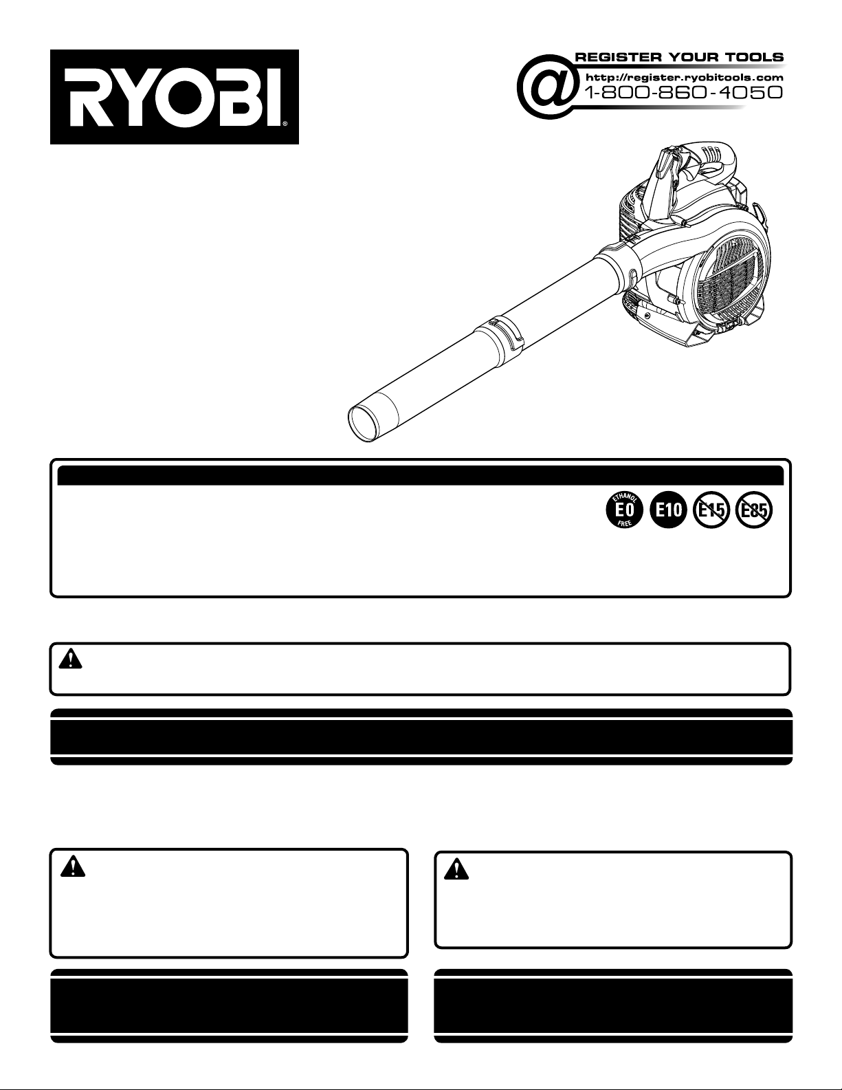
BLOWER
SOUFFLANTE
SOPLADORA
RY09466
ALL VERSIONS
TOUTES LES VERSIONS
TODAS LAS VERSIONES
NOTICE AVIS AVISO
Do not use E15 or E85 fuel (or fuel containing greater than 10% ethanol) in this product. It is
a violation of federal law and will damage the unit and void your warranty.
Ne pas utiliser d’essence E15 ou E85 (ou un carburant contenant plus de 10 % d’éthanol) dans
ce produit. Une telle utilisation représente une violation de la loi fédérale et endommagera l’appareil et annulera la garantie.
No utilice combustibles E15 o E85 (ni combustibles que contengan más de 10 % de etanol) con este producto. Esto constituye
una violación a la ley federal, dañará la unidad y anulará la garantía.
Your blower has been engineered and manufactured to our high standard for dependability, ease of operation, and operator
safety. When properly cared for, it will give you years of rugged, trouble-free performance.
WARNING: To reduce the risk of injury, the user must read and understand the operator’s manual before using this
product. If you do not understand the warnings and instructions in the operator’s manual, do not use this product.
SAVE THIS MANUAL FOR FUTURE REFERENCE
Cette soufflante a été conçue et fabriquée conformément à
nos strictes normes de fiabilité, simplicité d’emploi et sécurité
d’utilisation. Correctement entretenue, elle vous donnera des
années de fonctionnement robuste et sans problème.
AVERTISSEMENT : Pour réduire les risques de
blessures, l’utilisateur doit lire et veiller à bien comprendre
le manuel d’utilisation avant d’employer ce produit. Si tous
les avertissements et toutes les consignes de sécurités et
instructions du manuel d’utilisation ne sont pas bien compris,
ne pas utiliser ce produit.
CONSERVER CE MANUEL POUR
FUTURE RÉFÉRENCE
Su sopladora ha sido diseñada y fabricada de conformidad
con las estrictas normas para brindar fiabilidad, facilidad de
uso y seguridad para el operador. Con el debido cuidado, le
brindará muchos años de sólido y eficiente funcionamiento.
ADVERTENCIA: Para reducir el riesgo de lesiones,
el usuario debe leer y comprender el manual del operador antes
de usar este producto. Guarde este manual del operador y
estúdielo frecuentemente para lograr un funcionamiento seguro
y continuo de este producto
GUARDE ESTE MANUAL PARA
FUTURAS CONSULTAS
Page 2

See this fold-out section for all the figures
referenced in the operator’s manual.
Voir que cette section d’encart pour toutes les figures a
adressé dans le manuel d’utilisation.
Vea esta sección de la página desplegable para todas las
figuras mencionó en el manual del operador.
ii
Page 3
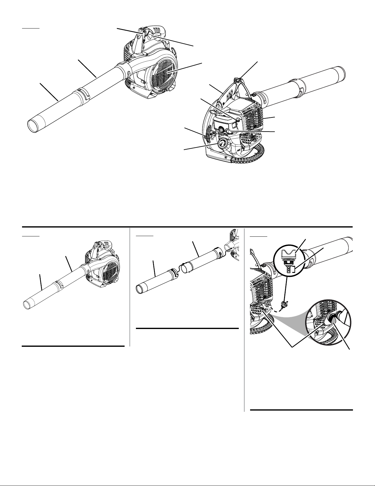
Fig. 1
C
D
B
E
I
A
F
L
A - Sweeper nozzle (embout éventail, boquilla para barrer)
B - Upper blower tube (tube de soufflante supérieur, tubo superior de la
sopladora)
C - Cruise control lever (commande de vitesse, control de crucero)
D - Throttle trigger (gâchette d’accélérateur, gatillo del acelerador)
E - Air inlet cover (recouvrement pour entrée d’air, cubierta de la entrada de
aire)
Fig. 2
Fig. 3
B
A
H
G
J
K
F - Starter grip and rope (poignée du lanceur, mango del arrancador)
G - Choke lever (levier de volet de départ, palanca de arranque)
H - Upper handle (poignée supérieure, mango superior)
I - Stop switch (commutateur d’arrêt, interruptor del apagado)
J - Muffler (silencieux, silenciador)
K - Primer bulb (poire d’amorçage, bomba de cebado)
L - Fuel cap (bouchon du réservoir, tapa del tanque de combustible)
B
Fig. 4
A
B
A
A - Sweeper nozzle (embout éventail, boquilla
para barrer)
B - Upper blower tube (tube de soufflante
supérieur, tubo superior de la sopladora)
A - Sweeper nozzle (embout éventail, boquilla
para barrer )
B - Upper blower tube (tube de soufflante
supérieur, tubo superior de la sopladora)
D
A - Oil cap/dipstick (bouchon/jauge d’huile, tapa
de relleno de aceite / varilla medidora de
aceite)
B - Hatched area (zone hachurée, área cubierta
con rayas entrecruzadas)
C - Funnel (entonnoir, embudo)
D - Oil fill hole (orifice de remplissage d’huile,
agujero de llenado de aceite)
C
iii
Page 4
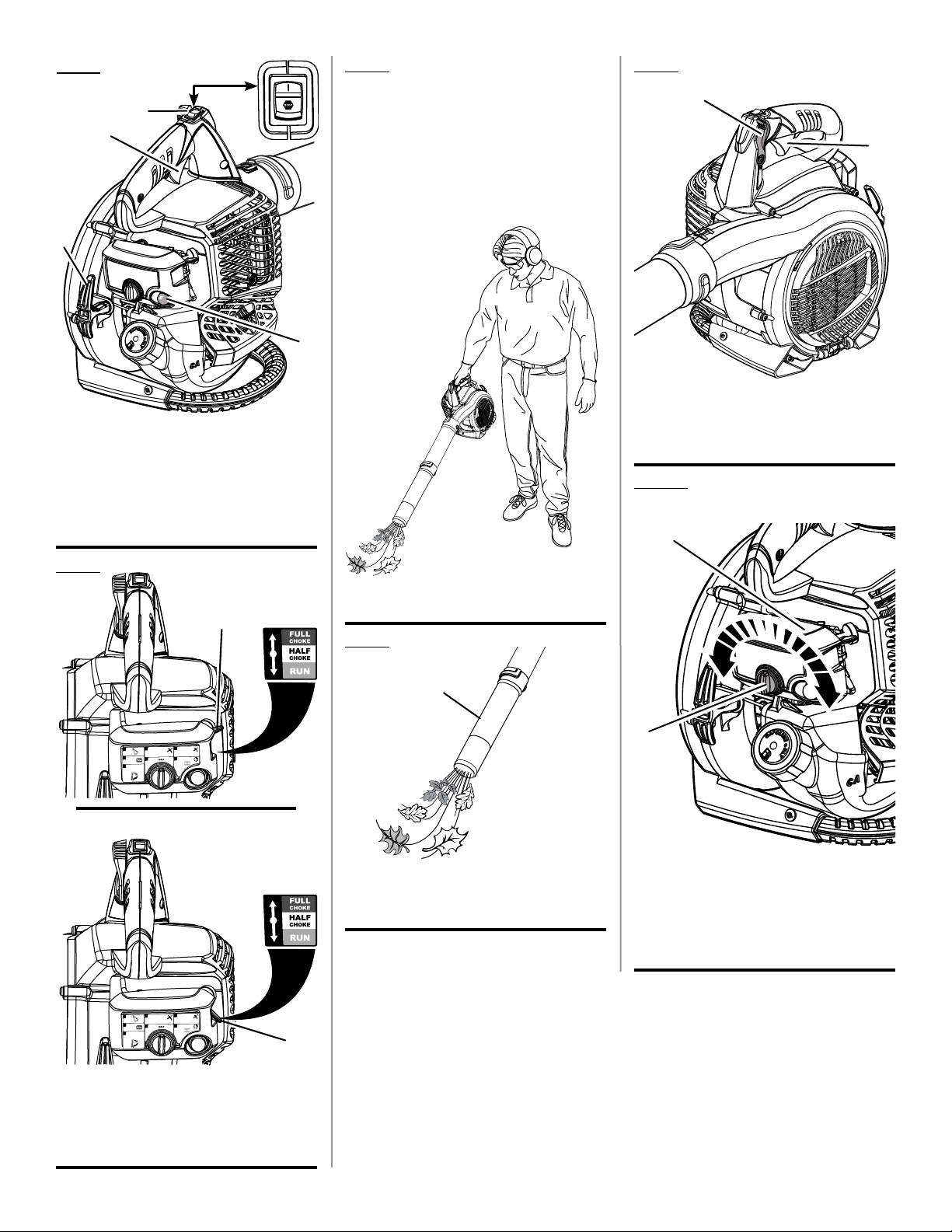
Fig. 5
Fig. 7
Fig. 9
A
B
D
C
A - Stop switch (commutateur d’arrêt,
interruptor del apagado)
B - Throttle trigger (gâchette d’accélérateur,
gatillo del acelerador)
C - Primer bulb (poire d’amorçage, bomba de
cebado)
D - Starter grip and rope (poignée du lanceur,
mango del arrancador)
PROPER BLOWER OPERATING POSITION
POSITION D’UTILISATION ADÉQUATE DE
LA SOUFFLANTE
POSICIÓN DE FUNCIONAMIENTO
CORRECTA DE LA SOPLADORA
A
B
A - Cruise control lever (commande de vitesse,
control de crucero)
B - Throttle trigger (gâchette d’accélérateur,
gatillo del acelerador)
Fig. 10
B
Fig. 6
1
PRIME
2
SET TO
3
LOCK
THROTTLE LEVER
1
PRIME
2
SET TO
3
LOCK
THROTTLE LEVER
x10
x10
4
PULL UNTIL
ENGINE ATTEMPTS
TO START
5
SET TO
4
PULL UNTIL
ENGINE ATTEMPTS
TO START
5
SET TO
A
C
Fig. 8
A
6
PULL UNTIL
ENGINE STARTS
(6X MAX)
(4X MAX)
7
WAIT 15 SEC
SET TO
B
A - Sweeper nozzle (embout éventail, boquilla
para barrer)
6
PULL UNTIL
ENGINE STARTS
(6X MAX)
(4X MAX)
7
WAIT 15 SEC
SET TO
C
A
A - Turn the dial to open and close (tourner
le cadran pour ouvrir et fermeture, gire el
selector para abrirla y cerrar )
B - Air filter cover (couvercle du filtre à air, tapa
de la cámara de ventilación)
A - Full choke position (position de volet de
départ ouvert, posición de arranque)
B - Run position (position de marche, posición
de marcha)
C - Choke lever (levier de volet de départ,
palanca de arranque)
iv
Page 5
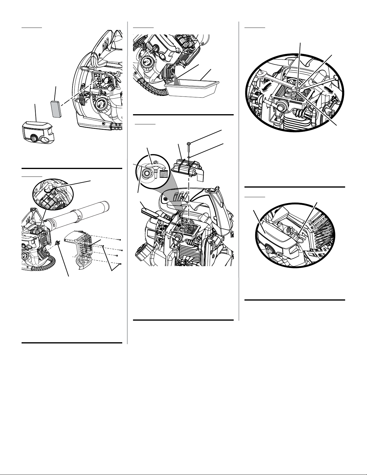
Fig. 11
Fig. 13
Fig. 15
C
A
A
B
B
A
A - Air filter cover (couvercle du filtre à air, tapa
de la cámara de ventilación)
B - Air filter (filtre à air, filtro de aire)
Fig. 12
C
B
A - Lubricant (lubrifiant, lubricante)
B - Container (conteneur, recipiente)
Fig. 14
B
A
C
D
B
E
A - Retaining nut (écrou de retenue, tuerca de
retencion)
B - Adjusting nut (écrou de réglage, tuerca de
ajuste)
C - Stud (goujon, elemento estructural)
Fig. 16
A
B
D
A
A - Screws (vis, tornillos)
B - Engine cover (couvercle moteur, cubierta del
motor)
C - Spark plug wire (fil de bougie, cable de la
bujía)
D - Oil fill cap/dipstick (bouchon remplit d’huile /
jauge d’huile, tapa de relleno de aceite/varilla
medidora de aceite)
A - Feeler gauge (jauge d’épaisseur, calibrador
de separaciones)
B - Rocker arm (culbuteur, balancín)
C - Rocker arm cover (cache -culasse, tapa del
balancín)
D - Screw (vis, tornillo)
E - O-ring (joint torique, anillo en “O”)
A - Idle speed screw (vis de ralenti, tornillo de
ajuste de la velocidad en vacío)
B - Air filter cover (couvercle du filtre à air, tapa
del filtro de aire)
v
Page 6

TABLE OF CONTENTS
TABLE DES MATIÈRES / ÍNDICE DE CONTENIDO
Introduction ......................................................................................................................................................................2
Introduction / Introducción
General Safety Rules ........................................................................................................................................................ 3
Règles de sécurité générales / Reglas de seguridad generales
Specific Safety Rules ........................................................................................................................................................ 4
Règles de sécurité particulières / Reglas de seguridad específicas
Symbols ............................................................................................................................................................................ 5
Symboles / Símbolos
Features ............................................................................................................................................................................6
Caractéristiques / Características
Assembly .......................................................................................................................................................................6-7
Assemblage / Armado
Operation .......................................................................................................................................................................7-9
Utilisation / Funcionamiento
Maintenance ..............................................................................................................................................................10-12
Entretien / Mantenimiento
Troubleshooting .............................................................................................................................................................. 13
Dépannage / Solución de problemas
Warranty .........................................................................................................................................................................14
Garantie / Garantía
Parts Ordering and Service ...............................................................................................................................Back Page
Commande de pièces et réparation / Pedidos de piezas y servicio ......................................................... Page arrière / Pág. posterior
INTRODUCTION
INTRODUCTION / INTRODUCCIÓN
This product has many features for making its use more pleasant and enjoyable. Safety, performance, and dependability
have been given top priority in the design of this product making it easy to maintain and operate.
* * *
Ce produit offre de nombreuses fonctions destinées à rendre son utilisation plus plaisante et satisfaisante. Lors de la
conception de ce produit, l’accent a été mis sur la sécurité, les performances et la fiabilité, afin d’en faire un outil facile à
utiliser et à entretenir.
* * *
Este producto ofrece numerosas características para hacer más agradable y placentero su uso. En el diseño de este producto
se ha conferido prioridad a la seguridad, el desempeño y la fiabilidad, por lo cual se facilita su manejo y mantenimiento.
2 - English
Page 7

GENERAL SAFETY RULES
WARNING:
Read and understand all instructions. Failure to follow
all instructions listed below may result in electric shock,
fire and/or serious personal injury.
Do not allow children or untrained individuals to use this
unit.
Do not start or operate the engine in a confined space,
building, near open windows, or in other unventilated
space where dangerous carbon monoxide fumes can
collect. Carbon monoxide, a colorless, odorless, and
extremely dangerous gas, can cause unconsciousness
or death.
Always wear eye protection with side shields marked to
comply with ANSI Z87.1, along with hearing protection.
Failure to do so could result in objects being thrown into
your eyes and other possible serious injuries.
Keep all bystanders, children, and pets at least 50 feet
away.
Wear heavy long pants, long sleeves, boots, and gloves.
Do not wear loose-fitting clothing, short pants, sandals,
jewelry of any kind, or go barefoot.
To reduce the risk of injury associated with objects be-
ing drawn into rotating parts, do not wear loose clothing,
scarves, neck chains, etc. Secure long hair so it is above
shoulder level to prevent entanglement in any rotating
parts.
Do not operate this unit when you are tired, ill, upset, or
under the influence of alcohol, drugs, or medication.
Do not operate in poor lighting.
Keep all parts of your body away from any moving parts
and all hot surfaces of the unit.
Wear a face filter mask in dusty conditions to reduce the
risk of injury associated with the inhalation of dust.
Check the work area before each use. Remove all objects
such as rocks, broken glass, nails, wire, or string which
can be thrown or become entangled in the machine.
Keep firm footing and balance. Do not overreach. Over-
reaching can result in loss of balance or exposure to hot
surfaces.
Never operate the unit without a spark arrestor screen;
this screen is located inside the muffler.
Product users on United States Forest Service land, and
in some states, must comply with fire prevention regulations. This product is equipped with a spark arrestor;
however, other user requirements may apply. Check with
the federal, state, or local authorities in your area.
Before storing, allow the engine to cool.
Use only identical replacement parts and accessories.
Failure to do so may cause poor performance or possible
injury.
Maintain the unit per maintenance instructions in this
operator’s manual.
Inspect the unit before each use for loose fasteners, fuel
leaks, etc. Replace damaged parts.
Before cleaning, repairing, or inspecting, shut off the
engine and make certain all moving parts have stopped.
Disconnect the spark plug wire, and keep the wire away
from the plug to prevent starting.
Service on the blower must be performed by qualified
repair personnel only. Service or maintenance performed
by unqualified personnel could result in injury to the user
or damage to the product.
Use only identical replacement parts when servicing the
blower. Use of unauthorized parts may create a risk of
serious injury to the user, or damage to the product.
Do not use on a ladder, rooftop, tree, or other unstable
support. Stable footing on a solid surface enables better
control of the blower in unexpected situations.
3 - English
Page 8

SPECIFIC SAFETY RULES
Always hold the blower in your right hand during blower
operation.
To reduce the risk of hearing loss associated with sound
level(s), hearing protection is required.
To reduce the risk of injury associated with contacting
rotating parts, stop the engine before installing or
removing attachments. Do not operate without all guard(s)
and tubes in place. Always disconnect the spark plug
before performing maintenance or accessing any movable parts.
Do not point the blower nozzle in the direction of people
or pets.
Never run the unit without the blower tubes installed.
Never place objects inside the blower tubes.
Use only as directed in this operator’s manual.
Never place blower on any surface, except a hard, clean
surface when engine is running. Gravel, sand, and other
debris can be picked up by the air inlet and thrown at the
operator or bystanders, causing possible serious injuries.
Never use for spreading chemicals, fertilizers, toxic sub-
stances, or any other hazardous chemical.
Never use blower near fires, fireplaces, hot ashes, bar-
becue pits, etc., which may cause fire to spread.
This product is intended for infrequent use by homeown-
ers and other occasional users for such general applications as blowing leaves and lawn clippings, etc. It is not
intended for prolonged use. Prolonged periods of operation can cause circulatory problems in the user’s hands
due to vibration. For such use, it may be appropriate to
use a product having an anti-vibration feature.
FUELING
Fuel is highly flammable. Take precautions when using
to reduce the chance of serious personal injury.
Store fuel in a cool, well-ventilated area, safely away from
spark and/or flame-producing equipment.
Store fuel in containers specifically designed for this
purpose.
Only refuel outdoors and do not smoke while refueling.
Add fuel before starting the engine. Never remove the cap
of the fuel tank or add fuel while the engine is running or
when the engine is hot.
Do not smoke while handling fuel.
Loosen fuel cap slowly to release pressure and to keep
fuel from escaping around the cap.
Tighten the fuel cap securely after refueling.
Wipe spilled fuel from the unit. Move 30 feet away from
refueling site before starting engine.
Never attempt to burn off spilled fuel under any circum-
stances.
To reduce the risk of fire and burn injury, handle fuel with
care. It is highly flammable.
If fuel is spilled, do not attempt to start the engine but
move the machine away from the area of spillage and
avoid creating any source of ignition until fuel vapors
have dissipated.
Replace all fuel tank and container caps securely.
Empty fuel tank into a container approved for gasoline
and restrain the unit from moving before transporting in
a vehicle.
When draining the fuel tank, use an approved fuel storage
container in a well-ventilated area.
Select bare ground, stop engine, and allow to cool before
refueling.
Save these instructions. Refer to them frequently and use
them to instruct others who may use this tool. If you loan
someone this tool, loan them these instructions also.
4 - English
Page 9
SYMBOLS
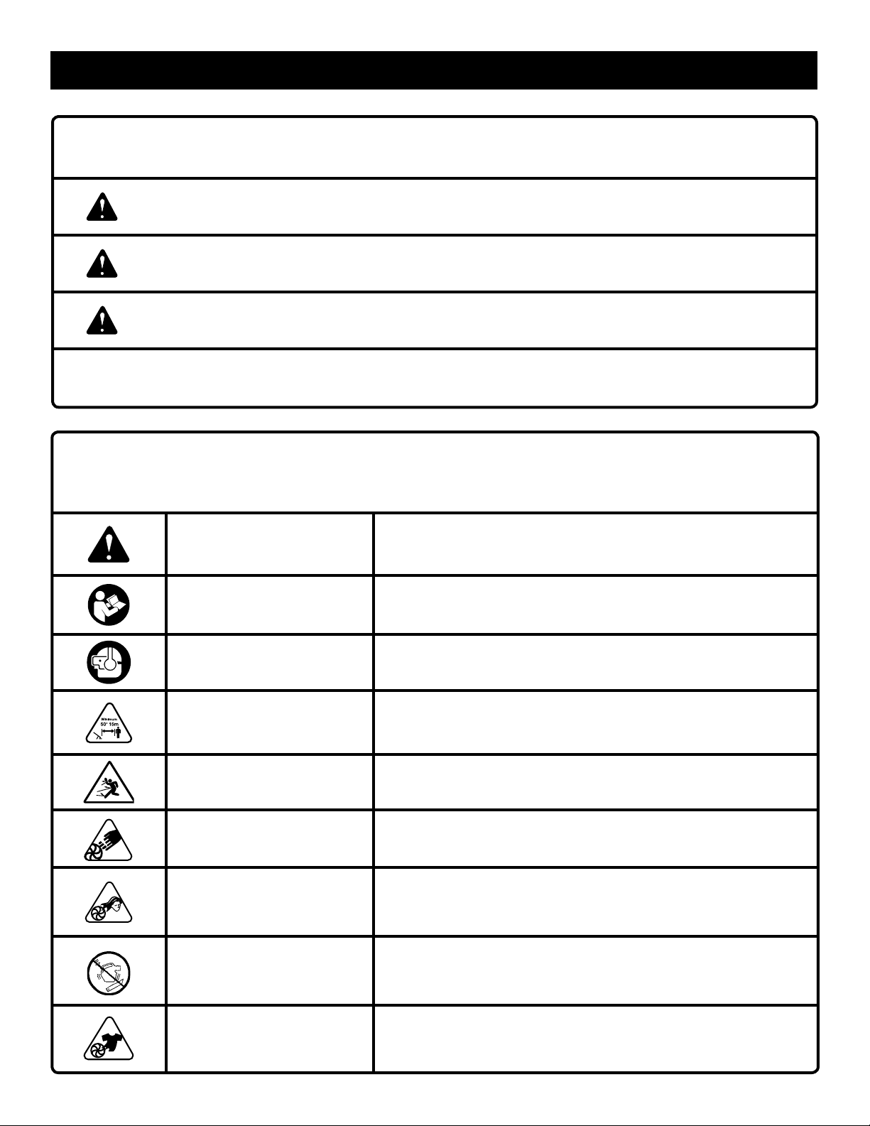
The following signal words and meanings are intended to explain the levels of risk associated with this product.
SYMBOL SIGNAL MEANING
DANGER:
WARNING:
CAUTION:
NOTICE:
Some of the following symbols may be used on this product. Please study them and learn their meaning. Proper
interpretation of these symbols will allow you to operate the product better and safer.
Indicates an imminently hazardous situation, which, if not avoided, will result
in death or serious injury.
Indicates a potentially hazardous situation, which, if not avoided, could result
in death or serious injury.
Indicates a potentially hazardous situation, which, if not avoided, may result in
minor or moderate injury.
(Without Safety Alert Symbol) Indicates important information not related to an
injury hazard, such as a situation that may result in property damage.
SYMBOL NAME EXPLANATION
Safety Alert Symbol Indicates a potential personal injury hazard.
Read Operator’s Manual
To reduce the risk of injury, user must read and understand operator’s manual before using this product.
Wear Eye and Hearing
Protection
Keep Bystanders Away Keep all bystanders at least 50 ft. away.
Ricochet
Air Inlet Cover
Long Hair Risk of long hair being drawn into air inlet.
Blower Tubes Do not run unit without tubes in place.
Loose Clothing Risk of loose clothing being drawn into air intake.
Always wear eye protection with side shields marked to comply
with ANSI Z87.1 as well as hearing protection when operating this
equipment.
Thrown objects can ricochet and result in personal injury or property
damage.
Do not run unit if the air inlet cover becomes opened, damaged,
or unsecured in any way. Contact with rotating impeller blades can
cause severe injury.
5 - English
Page 10
FEATURES
PRODUCT SPECIFICATIONS
Engine Displacement.......................................................................................................................................................30cc
Air Velocity:
*MPH ...........................................................................................................................................................................155
*CFM ...........................................................................................................................................................................400
Engine Lubricant Volume................................................................................................................................................65 ml
Weight .......................................................................................................................................................................10.4 lbs.
*Rated per ANSI B175.2
KNOW YOUR BLOWER
See Figure 1.
The safe use of this product requires an understanding of
the information on the tool and in this operator’s manual as
well as a knowledge of the project you are attempting. Before
use of this product, familiarize yourself with all operating
features and safety rules.
BLOWER TUBE AND NOZZLE
The blower tube and nozzle can be assembled and installed
on the blower without using any tools.
CRUISE CONTROL LEVER
The cruise control lever allows the user to operate the blower
without holding the throttle trigger. To slow the engine, simply
push the cruise control lever forward.
ASSEMBLY
UNPACKING
This product requires assembly.
Carefully remove the product and any accessories from
the box. Make sure that all items listed in the packing list
are included.
WARNING:
Do not use this product if any parts on the Packing List
are already assembled to your product when you unpack
it. Parts on this list are not assembled to the product by
the manufacturer and require customer installation. Use
of a product that may have been improperly assembled
could result in serious personal injury.
Inspect the product carefully to make sure no breakage
or damage occurred during shipping.
Do not discard the packing material until you have care-
fully inspected and satisfactorily operated the product.
If any parts are damaged or missing, please call
1-800-860-4050 for assistance.
ENGINE
The blower has a powerful 30cc engine with sufficient power
to handle tough blowing.
SWEEPER NOZZLE
The sweeper nozzle allows for more area to be covered during blower operation.
THROTTLE TRIGGER
The blower can be operated at any speed between idle and
full throttle.
PACKING LIST
Blower
Upper Blower Tube
Sweeper Nozzle
4-Cycle Engine Lubricant
Funnel
Operator’s Manual
NOTE: Read and remove all hang tags and store with your
Operator’s Manual.
WARNING:
If any parts are damaged or missing do not operate this
product until the parts are replaced. Use of the product
with damaged or missing parts could result in possible
serious personal injury.
6 - English
Page 11
ASSEMBLY
WARNING:
Do not attempt to modify this product or create accessories not recommended for use with this product. Any
such alteration or modification is misuse and could result
in a hazardous condition leading to possible serious
personal injury.
WARNING:
To prevent accidental starting that could cause serious
personal injury, always disconnect the engine spark plug
wire from the spark plug when assembling parts.
WARNING:
This product is intended for blower use only and is not
designed for vacuum use. Do not attempt to open the air
inlet cover that covers the impeller. Opening the air inlet
cover could result in contact with the impeller blades and
cause serious personal injuries.
ASSEMBLING THE BLOWER TUBES
See Figures 2 - 3.
Align raised tabs on blower housing outlet to the slots
on upper tube; slide together and tighten securely by
twisting. Check tightness after initial use and retighten if
needed.
Attach sweeper nozzle to upper blower tube by aligning
raised tabs on upper blower tube; slide together and
tighten securely by twisting. Check tightness after initial
use and retighten if needed.
To remove the tubes, rotate the tubes to unlock them and
remove from the blower housing outlet.
OPERATION
WARNING:
Do not allow familiarity with this product to make you
careless. Remember that a careless fraction of a second is
sufficient to inflict serious injury.
WARNING:
Always wear eye protection with side shields marked to
comply with ANSI Z87.1, along with hearing protection.
Failure to do so could result in objects being thrown into
your eyes and other possible serious injuries.
WARNING:
Do not use any attachments or accessories not recommended by the manufacturer of this product. The use of
attachments or accessories not recommended can result
in serious personal injury.
WARNING:
Operation of this equipment can create sparks that can
start fires around dry vegetation. A spark arrestor may
be required. The operator should contact local fire agencies for laws or regulations relating to fire prevention
requirements.
APPLICATIONS
You may use this product for the purposes listed below:
Clearing leaves and other debris from your lawn
Keeping decks and driveways free from leaves and pine
needles
7 - English
Page 12
OPERATION
ADDING/CHECKING ENGINE LUBRICANT
See Figure 4.
Engine lubricant has a major influence on engine performance and service life. This unit is shipped with a 20W50
engine lubricant to assist in the break-in period. For best
operating performance, continuing to use 20W50 engine
lubricant is recommended, however, SAE 30, 10W30, or
10W40 are all acceptable lubricants to use in this product.
Always use a 4-stroke motor lubricant that meets or exceeds
the requirements for API service classification SJ. Check
lubricant level before each use.
NOTE: Non-detergent or 2-cycle engine lubricants will damage the engine and should not be used.
To add engine lubricant:
NOTICE:
Attempting to start the engine before it has been properly
filled with lubricant will result in equipment failure.
Remove the cap and seal from lubricant bottle provided.
Unscrew the oil cap/dipstick and remove.
Using funnel provided, add entire bottle of engine
lubricant through oil fill hole.
Reinstall the oil cap/dipstick and secure.
To check engine lubricant level:
Set unit on a flat surface.
Wipe dipstick clean and re-seat in hole; do not rethread.
Remove dipstick again and check lubricant level.
Lubricant level should fall within the hatched area on the
dipstick.
If level is low, add engine lubricant until the fluid level rises
to the upper portion of the hatched area on the dipstick.
Replace and secure the oil cap/dipstick.
NOTICE:
Do not overfill. Overfilling the crankcase may cause
excessive smoke, oil loss, and engine damage.
OXYGENATED FUELS
NOTICE:
Do not use E15 or E85 fuel (or fuel containing greater
than 10% ethanol) in this product. It is a violation of
federal law and will damage the unit and void your
warranty.
Fuel system damage or performance problems resulting
from the use of an oxygenated fuel containing more than
the percentage of oxygenates stated below are not covered
under warranty.
Ethanol. Gasoline containing up to 10% ethanol by volume
(commonly referred to as E10) is acceptable. E15 and E85
are not.
FILLING THE TANK
WARNING:
Gasoline and its vapors are highly flammable and explosive. To prevent serious personal injury and property
damage, handle it with care. Keep away from ignition
sources and open flames, handle outdoors only, do not
smoke, and wipe up spills immediately.
Clean the surface around the fuel cap to prevent con-
tamination.
Loosen the fuel cap slowly by turning counterclock-
wise.
Pour the fuel carefully into the tank.
Clean and inspect the fuel cap gasket before replacing
the fuel cap.
Replace the fuel cap and tighten it by turning it clock-
wise.
Wipe spilled fuel from the product.
Move at least 30 ft. away from refueling area before
starting the product.
NOTE: It is normal for smoke to be emitted from a new
engine during first use.
WARNING:
Always shut off engine before fueling. Never add fuel to a
machine with a running or hot engine. Move at least 30 ft.
from refueling site before starting engine. Do not smoke
and stay away from open flames and sparks. Failure to
safely handle fuel could result in serious personal injury.
STARTING AND STOPPING
See Figures 5 - 6.
Blower should be on a flat, bare surface for starting.
Slowly press the primer bulb 10 times.
NOTE: After the 7th press, fuel should be visible in the
primer bulb. If it is not, continue to press the primer until
you see fuel in the bulb.
Set the choke lever to the FULL CHOKE position.
Do not squeeze the throttle trigger. Start the unit with the
cruise control lever in the IDLE position. Pull the starter
grip and rope sharply until engine attempts to run (no
more than 4 pulls).
Set the choke lever to the HALF CHOKE position.
Pull the starter grip and rope until the engine runs. Do not
pull the starter grip and rope more than six (6) times.
NOTE: If the engine does not start, return to the FULL
CHOKE position and repeat the steps that follow.
Allow the engine to run for 15 seconds, then set the choke
lever to the RUN position.
8 - English
Page 13
OPERATION
TO STOP THE ENGINE:
To stop the engine, depress the STOP switch to the stop
position “
HOT RESTART OF THE ENGINE:
Set the choke lever to the RUN position.
Set the cruise control lever to IDLE.
Do not squeeze the throttle to start a hot engine.
Pull the starter grip and rope until the engine runs.
IF ASSISTANCE IS REQUIRED FOR THIS PRODUCT:
Do not return this product to the retail store where it was
purchased. Please call our Customer Service Department
for any issues you may have.
For Help Call: 1-800-860-4050
”.
OPERATING THE BLOWER
See Figures 7 - 8.
WARNING:
Never run the unit without the blower tubes installed or
the air inlet cover securely closed. Use of an improperly
assembled unit could result in serious personal injury.
WARNING:
Always hold the blower away from your body with the
handle in your right hand, keeping clearance between
your body and the product. The muffler side of the blower
should be away from your body. Any contact with the
housing can result in burns and/or other serious personal
injury.
NOTICE:
Always operate your product in compliance with all applicable laws and ordinances.
Start the blower. Refer to Starting and Stopping earlier
in this manual. Hold the blower with the upper handle in
your right hand.
WARNING:
Do not place blower on top of or near loose debris or
gravel. Debris may be sucked into blower intake vent
resulting in possible damage to the unit and could result
in serious personal injury.
To keep from scattering debris, blow around the outer
edges of a debris pile. Never blow directly into the center
of a pile.
Operate power equipment at reasonable hours only - not
early in the morning or late at night when people might
be disturbed. Comply with the times listed in local ordinances.
To reduce sound levels, limit the number of pieces of
equipment used at any one time.
Conserve water by using power blowers instead of hoses
for many lawn and garden applications, including areas
such as gutters, screens, patios, grills, porches, and
gardens.
Operate blower at the lowest possible throttle speed to
do the job.
Check your equipment before operation, especially the
muffler, air intakes, and air filters.
Use rakes and brooms to loosen debris before blowing.
In dusty conditions, slightly dampen surfaces when water
is available.
Watch out for children, pets, open windows, or freshly
washed cars, and blow debris safely away.
Hold blower, as shown in Figure 7, so the air stream can
work close to the ground.
After using blowers or other equipment, CLEAN UP!
Dispose of debris properly.
Use the sweeper nozzle for the every-day blowing op-
eration. This nozzle allows for more area to be covered
during the blowing operation.
CRUISE CONTROL
See Figure 9.
The cruise control can be used to operate the blower without
holding the throttle trigger.
To engage the cruise control:
Pull cruise control lever back towards user, and stop at
the desired throttle setting.
To release the cruise control, push cruise control lever
all the way towards the front of unit.
9 - English
Page 14
MAINTENANCE
WARNING:
When servicing, use only identical replacement parts.
Use of any other parts could create a hazard or cause
product damage.
WARNING:
Always wear eye protection with side shields marked to
comply with ANSI Z87.1, along with hearing protection.
Failure to do so could result in objects being thrown into
your eyes and other possible serious injuries.
WARNING:
Before inspecting, cleaning, or servicing the machine,
shut off engine, wait for all moving parts to stop, and
disconnect spark plug wire and move it away from spark
plug. Failure to follow these instructions can result in
serious personal injury or property damage.
GENERAL MAINTENANCE
Avoid using solvents when cleaning plastic parts. Most
plastics are susceptible to damage from various types of
commercial solvents and may be damaged by their use.
Use clean cloths to remove dirt, dust, lubricant, grease, etc.
FUEL CAP, TANK, AND LINES
WARNING:
Check for fuel leaks. A leaking fuel cap, tank, or lines
are a fire hazard and must be replaced immediately. If
you find any leaks, correct the problem before using the
product. Failure to do so could result in a fire that could
cause serious personal injury.
The fuel cap contains a non-serviceable filter and a
check valve. A clogged fuel filter will cause poor engine
performance. If performance improves when the fuel cap
is loosened, check valve may be faulty or filter clogged.
Replace fuel cap if required.
SPARK PLUG REPLACEMENT
This engine uses a Champion RY4C or equivalent spark plug
with .025 in. electrode gap. Use an exact replacement and
replace annually.
NOTICE:
Be careful not to cross-thread the spark plug. Crossthreading will seriously damage the product.
CHANGING ENGINE LUBRICANT
See Figures 12 -13.
WARNING:
Do not at any time let brake fluids, gasoline, petroleumbased products, penetrating lubricants, etc., come in contact with plastic parts. Chemicals can damage, weaken or
destroy plastic which may result in serious personal injury.
You can often make adjustments and repairs described here.
For other repairs, have the blower serviced by an authorized
service center.
CLEANING THE AIR FILTER
See Figure 10 - 11.
For proper performance and long life, keep air filter clean.
Remove the air filter cover by turning the dial counter
clockwise while gently pulling on the cover.
Rinse filter with clean water.
Gently squeeze filter until excess water is removed.
Replace filter.
Place the air filter cover back on the unit. Turn dial clock-
wise until cover is secure.
WARNING:
Do not change engine lubricant while it is hot. Accidental
contact with hot engine lubricant could result in serious
burns.
For best performance, engine lubricant should be changed
after every 25 hours of operation.
To change the engine lubricant:
Stop the engine. Allow the engine to cool completely
before proceeding.
Remove the screw from the top engine cover and set
aside.
Remove the screws from engine cover. Remove the cover
and set aside.
Disconnect the spark plug wire.
Remove the oil fill cap/dipstick.
Tip blower on its side and allow lubricant to drain from
the oil fill hole into an approved container.
NOTE: Drain the lubricant while the engine is still warm
but not hot. Warm lubricant will drain quickly and more
completely.
10 - English
Page 15

MAINTENANCE
Return the blower to an upright position and refill with
lubricant following the instructions in the Adding/Check-
ing Engine Lubricant section previously in this manual.
Reinstall the bottom engine cover. Replace the screws
and tighten securely.
Replace the screw in the top engine cover and tighten
securely.
NOTE: Used lubricant should be disposed of at an approved
disposal site. See your local retailer for more information.
ADJUSTING CAMSHAFT-TO-ROCKER ARM
CLEARANCE
See Figures 14 - 15.
Inspect the camshaft-to-rocker arm clearance after every
25 hours of operation. This should be done in a clean, dustfree environment.
NOTE: This procedure requires partial disassembly of the
engine. If you are unsure if you are qualified to perform this
operation, take the unit to an authorized service center.
Stop the engine. Allow the engine to cool completely
before proceeding.
Remove screws from the engine cover. Remove engine
cover and set aside.
Disconnect the spark plug wire.
Using a Torx screwdriver, remove the screw from the
rocker arm cover. Remove the cover and set aside.
Position camshaft by pulling the recoil starter grip just
until the deep hole in the camshaft gear is located at the
6 o’clock position.
Place the feeler gauge under each rocker arm and
measure the gap. The gap should be between .006 in.
(0.15 mm) and .008 in. (0.20 mm) for both rocker arms.
NOTE: Use a standard automotive feeler gauge. The
.006 in. (0.15 mm) feeler gauge should slide between
the rocker arm and valve stem with a slight amount of
resistance but without binding. The 0.008 in. (0.20 mm)
feeler gage should not slide between the rocker arms and
the cam lobes — it should be held tight.
If the valve clearance is not between .006 in. (0.15 mm)
and .008 in. (0.20 mm), the clearance should be adjusted
as follows:
While holding a wrench on the flats of the adjusting
nut with one hand, loosen the retaining nut with a
second wrench. Take care not to loosen the stud.
Rotate the adjusting nut until it touches the feeler
gauge. Once the gap setting is correct, hold the
wrench on the flats of the adjusting nut and retighten
the retaining nut securely.
Adjust the second rocker arm, if necessary.
Replace the rocker arm cover and screw; tighten securely.
Replace the top engine cover and screw; tighten securely.
WARNING:
Ensure all engine cover and all engine parts are completely and properly reassembled before starting engine.
Failure to correctly reassemble engine can result in serious injury or property damage.
STORING THE PRODUCT
Clean all foreign material from the product. Store idle unit
indoors in a dry, well-ventilated area that is inaccessible
to children. Keep away from corrosive agents such as
garden chemicals and de-icing salts.
Abide by all ISO and local regulations for the safe storage
and handling of gasoline.
When storing 1 month or longer:
Drain all fuel from tank into a container approved for
gasoline. Run engine until it stops.
HIGH ALTITUDE ENGINE OPERATION
Please have an authorized service center adjust this engine
if it is to be run above 2000 feet. Failure to do so may result
in poor engine performance and increased emissions. An
engine adjusted for high altitudes can not be run at 2000
feet or lower. In doing so, the engine will overheat and cause
serious engine damage. Please have an authorized service
center restore high altitude modified engines to the original
factory specification before operating below 2000 feet.
11 - English
Page 16

MAINTENANCE
MAINTENANCE SCHEDULE
Maintenance Inspect For Damage Clean Every Replace Every Replace Every
Part Before Each Use 5 Hours 25 Hours or Yearly 50 Hours or Yearly
AIR FILTER ASSY
INCLUDES:
FILTER ................................................................................ X ........................................... X
CARBURETOR ASSY
INCLUDES:
HEAT DAM ................................x
GASKETS ..................................x
FUEL TANK ASSY
INCLUDES:
FUEL LINES ............................. X
FUEL CAP ................................ X
FUEL FILTER ............................ X
IGNITION ASSY
INCLUDES:
SPARK PLUG .................................................................................................................................................................X
*NOTICE: THE USE OF EMISSION CONTROL COMPONENTS OTHER THAN THOSE DESIGNED FOR THIS UNIT IS A VIOLATION OF
FEDERAL LAW.
CALL US FIRST
For any questions about operating or maintaining your product,
call the Ryobi
Your product has been fully tested prior to shipment to ensure
your complete satisfaction.
® Help Line!
12 - English
Page 17

TROUBLESHOOTING
IF THESE SOLUTIONS DO NOT SOLVE THE PROBLEM, CONTACT YOUR AUTHORIZED SERVICING DEALER.
PROBLEM CAUSE REMEDY
Engine fails to start. No fuel in tank.
Spark plug shorted or fouled.
Spark plug is broken. (cracked
porcelain or electrodes broken)
Ignition lead wire shorted, broken, or
disconnected from spark plug.
Ignition inoperative.
Engine hard to start. Water in gasoline or stale fuel.
Engine is under or over choked.
Weak spark at spark plug.
Engine lacks power. Air filter clogged. Clean air filter. Refer to Cleaning the
Engine starts, runs, and accelerates
but will not idle
Idle speed screw on carburetor needs
adjustment.
Fill tank.
Replace spark plug.
Replace spark plug.
Replace lead wire or attach to spark
plug.
Contact authorized service center.
Drain entire system and refill with fresh
fuel.
Adjust choke as necessary.
Contact authorized service center.
Air Filter earlier in this manual.
Turn idle speed screw clockwise to in-
crease idle speed. See Figure 16.
Engine emits too much smoke Too much oil in crankcase. Drain lubricant and refill with correct
amount of 10W-30 engine lubricant. See
Adding/Checking Engine Lubricant in
the Operation section of this manual.
Starter grip and rope cannot be pulled Oil has entered the combustion
chamber.
This is usually caused by storing the unit
for an extended time with the engine in
an upside-down position. Remove and
clean the spark plug. Drain the oil out
of the spark plug hole, then reinstall the
spark plug.
13 - English
Page 18

WARRANTY
LIMITED WARRANTY STATEMENT
Techtronic Industries North America, Inc., warrants to the
original retail purchaser that this RYOBI® brand outdoor
product is free from defect in material and workmanship
and agrees to repair or replace, at Techtronic Industries
North America, Inc.’s, discretion, any defective product
free of charge within these time periods from the date of
purchase.
Three years if the product is used for personal, family
or household use;
90 days, if used for any other purpose, such as
commercial or rental.
This warranty extends to the original retail purchaser
only and commences on the date of the original retail
purchase.
Any part of this product found in the reasonable judgment
of Techtronic Industries North America, Inc. to be defective
in material or workmanship will be repaired or replaced
without charge for parts and labor by an authorized service
center for RYOBI® brand outdoor products (Authorized
Ryobi Service Center).
The product, including any defective part, must be returned
to an authorized Ryobi service center within the warranty
period. The expense of delivering the product to the service
center for warranty work and the expense of returning it
back to the owner after repair or replacement will be paid
by the owner. Techtronic Industries North America, Inc.’s,
responsibility in respect to claims is limited to making the
required repairs or replacements and no claim of breach of
warranty shall be cause for cancellation or rescission of the
contract of sale of any RYOBI® brand outdoor product. Proof
of purchase will be required by the dealer to substantiate
any warranty claim. All warranty work must be performed
by an authorized service dealer.
This warranty is limited to ninety (90) days from the date
of original retail purchase for any RYOBI® brand outdoor
product that is used for rental or commercial purposes, or
any other income-producing purpose.
This warranty does not cover any product that has been
subject to misuse, neglect, negligence, or accident, or that
has been operated in any way contrary to the operating
instructions as specified in this operator’s manual. This
warranty does not apply to any damage to the product that
is the result of improper maintenance or to any product
that has been altered or modified. The warranty does not
extend to repairs made necessary by normal wear or by the
use of parts or accessories which are either incompatible
with the RYOBI® brand outdoor product or adversely affect
its operation, performance, or durability. In addition, this
warranty does not cover:
A. Tune-ups – Spark Plugs, Carburetor, Carburetor
Adjustments, Ignition, Filters
B. Wear items – Bump Knobs, Outer Spools, Cutting
Lines, Inner Reels, Starter Pulleys, Starter Ropes, Drive
Belts, Tines, Felt Washers, Hitch Pins, Mulching Blades,
Blower Fans, Blower and Vacuum Tubes, Vacuum Bag
and Straps, Guide Bars, Saw Chains
Techtronic Industries North America, Inc., reserves the
right to change or improve the design of any RYOBI
outdoor product without assuming any obligation to modify
any product previously manufactured.
ALL IMPLIED WARRANTIES ARE LIMITED IN DURATION
TO THE STATED WARRANTY PERIOD. ACCORDINGLY,
ANY SUCH IMPLIED WARRANTIES INCLUDING
MERCHANTABILITY, FITNESS FOR A PARTICULAR
PURPOSE, OR OTHERWISE, ARE DISCLAIMED
IN THEIR ENTIRETY AFTER THE EXPIRATION OF
THE APPROPRIATE THREE-YEAR OR NINETY-DAY
WARRANTY PERIOD. TECHTRONIC INDUSTRIES
NORTH AMERICA, INC.’S, OBLIGATION UNDER THIS
WARRANTY IS STRICTLY AND EXCLUSIVELY LIMITED TO
THE REPAIR OR REPLACEMENT OF DEFECTIVE PARTS
AND TECHTRONIC INDUSTRIES NORTH AMERICA,
INC., DOES NOT ASSUME OR AUTHORIZE ANYONE
TO ASSUME FOR THEM ANY OTHER OBLIGATION.
SOME STATES DO NOT ALLOW LIMITATIONS ON HOW
LONG AN IMPLIED WARRANTY LASTS, SO THE ABOVE
LIMITATION MAY NOT APPLY TO YOU. TECHTRONIC
INDUSTRIES NORTH AMERICA, INC., ASSUMES NO
RESPONSIBILITY FOR INCIDENTAL, CONSEQUENTIAL,
OR OTHER DAMAGES INCLUDING, BUT NOT LIMITED
TO, EXPENSE OF RETURNING THE PRODUCT TO AN
AUTHORIZED RYOBI SERVICE CENTER AND EXPENSE
OF DELIVERING IT BACK TO THE OWNER, MECHANIC’S
TRAVEL TIME, TELEPHONE OR TELEGRAM CHARGES,
RENTAL OF A LIKE PRODUCT DURING THE TIME
WARRANTY SERVICE IS BEING PERFORMED, TRAVEL,
LOSS OR DAMAGE TO PERSONAL PROPERTY, LOSS
OF REVENUE, LOSS OF USE OF THE PRODUCT, LOSS
OF TIME, OR INCONVENIENCE. SOME STATES DO NOT
ALLOW THE EXCLUSION OR LIMITATION OF INCIDENTAL
OR CONSEQUENTIAL DAMAGES, SO THE ABOVE
LIMITATION OR EXCLUSION MAY NOT APPLY TO YOU.
This warranty gives you specific legal rights, and you may
also have other rights which vary from state to state.
This warranty applies to all RYOBI® brand outdoor products
manufactured by or for Techtronic Industries North America,
Inc., and sold in the United States and Canada.
To locate your nearest Authorized Ryobi Service Center,
dial 1-800-860-4050.
® brand
14 - English
Page 19

RÈGLES DE SÉCURITÉ GÉNÉRALES
AVERTISSEMENT :
Lire attentivement toutes les instructions. Le non-
respect de toutes les instructions ci-dessous peut
entraîner un choc électrique, un incendie et / ou des
blessures graves voire la mort.
Ne pas laisser des enfants ou personnes n’ayant pas reçu
une formation adéquate utiliser cet unité.
Ne pas démarrer ou faire tourner le moteur dans un
espace confine, de bâtiment, à proximité des fenêtres
ouverts, autre ou des zones sans ventilation où des
vapeurs toxiques de monoxyde de carbone peuvent
s’accumuler. Le monoxyde de carbone, un gaz incolore,
inodore et extrêmement toxique peut causer une perte
de conscience et être mortel.
Toujours porter une protection oculaire avec écrans
latéraux certifiée conforme à la norme ANSI Z87.1, avec
protection auditive. Si cette précaution n’est pas prise,
des objets peuvent être projetés dans les yeux et d’autres
lésions graves.
Garder les badauds, enfants et visiteurs à une distance
de 15 m (50 pi).
Porter des pantalons longs, manches longues, des
chaussures de travail et des gants épais. Ne pas porter
de vêtements amples, shorts, bijoux quels qu’ils soient,
sandales et ne pas travailler pieds nus.
Pour réduire les risques de happement par les pièces
en mouvement, ne pas porter de vêtements amples,
foulards, colliers ou autres articles de même nature.
Attacher les cheveux longs pour les maintenir au-dessus
des épaules, afin qu’ils ne se prennent pas dans les
pièces en mouvement.
Ne pas utiliser cet unité en état de fatigue, si l’on est
souffrant, si vous êtes bouleversé, ou sous l’influence
de l’alcool, de drogues ou de médicaments.
Ne pas travailler sous un éclairage insuffisant.
Garder toutes les parties du corps à l’écart des pièces
en mouvement et des parties brûlantes de l’outil.
Porter un masque facial filtrant dans les milieux pous-
siéreux afin de réduire le risque de lésions lié à l’inhalation
de poussière.
Examiner la zone de travail avant chaque utilisation. La
débarrasser de tous les objets tels que cailloux, verre
brisé, clous, fils métalliques, cordes, etc. risquant d’être
projetés ou de se prendre dans la machine.
Se tenir bien campé et en équilibre. Ne pas travailler
hors de portée. Le travail hors de portée risque de faire
perdre l’équilibre ou de causer un contact avec les pièces
brûlantes.
Ne jamais utiliser l’outil sans le pare-étincelles, qui se
trouve dans le silencieux.
Les produits utilisés sur les territoires des services
forestiers des États-Unis et de certains états doivent être
conformes aux réglementations de lutte contre l’incendie.
Cet outil est doté d’un pare-étincelles, toutefois, d’autres
dispositifs peuvent être requis. Consulter les autorités
locales et gouvernementales.
Laisser le moteur refroidir avant de remiser l’outil.
Utiliser exclusivement des pièces identiques à celles
d’origine et accessoires. Ne pas suivre cette recommandation peut entraîner un mauvais fonctionnement et des
blessures.
Entretenir l’outil conformément aux instructions de ce
manuel d’utilisation.
Inspecter l’outil avant chaque utilisation pour s’assurer
qu’il n’y a pas de pièces desserrées, de fuites de
carburant, etc. Remplacer les pièces endommagées.
Avant de nettoyer, réparer ou inspecter, arrêter le mo-
teur et vérifier que toutes les pièces en mouvement sont
immobilisées. Déconnecter le fil de bougie et le garder
à l’écart de la bougie afin d’empêcher un démarrage
accidentel.
Le dépannage de la soufflante doit exclusivement être
confié à un personnel qualifié. Les réparations ou entretiens par des personnes non qualifiées peuvent entraîner des blessures ou dommages à l’outil.
Utiliser exclusivement des pièces identiques à celles
d’origine pour les réparations. L’usage de pièces non
autorisées peut présenter des risques de blessures ou
de dommage pour l’outil.
Ne pas utiliser l’outil sur une échelle ou un support
instable. Une bonne tenue et un bon équilibre permettent
de mieux contrôler l’outil en cas de situation imprévue.
3 - Français
Page 20

RÈGLES DE SÉCURITÉ PARTICULIÈRES
Toujours tenir la soufflante avec la main droite pendant
le soufflage.
Pour réduire les risques de perte de l’ouïe causée par le
niveau sonore, porter une protection auditive.
Pour réduire les risques de blessures infligées par des
pièces en rotation, arrêter le moteur avant d’installer ou
de retirer des accessoires. Ne pas utiliser la machine sans
que tous les dispositifs de protection et les tubes soient
en place. Toujours débrancher le fil de bougie avant de
procéder à un entretien ou d’accéder à des pièces en
mouvement.
Ne pas diriger la soufflante vers une personne ou un
animal.
Ne jamais utiliser la soufflante sans les tubes installés.
Ne jamais rien insérer dans les tubes.
Utiliser exclusivement selon les instructions de ce manuel.
Ne jamais placer la soufflante en marche sur une surface,
sauf si celle-ci est dure et propre. Le gravier, le sable et
les autres débris peuvent être aspirés dans l’entrée d’air
et projetés en direction de l’utilisateur ou des personnes
à proximité, ce qui peut entraîner des blessures graves.
Ne jamais utiliser la soufflante à proximité d’un feu, d’un
poêle, de cendres chaudes, d’un barbecue, etc., sans
quoi le feu risque de se propager.
Ne jamais utiliser la soufflante à proximité d’un feu, d’un
poêle, de cendres chaudes, d’un barbecue, etc., sans
quoi le feu risque de se propager.
Ce produit est conçu pour les personnes qui prévoient
l’utiliser de manière peu fréquente pour des applications
générales par exemple, souffler les feuilles et les brins
d’herbe, etc.; l’outil peut également convenir à d’autres
utilisateurs occasionnels. Elle n’est pas conçue pour un
usage prolongé. Les périodes d’utilisation prolongée
peuvent entraîner des problèmes circulatoires dans les
mains de l’opérateur, causés par les vibrations. Pour ce
type d’application, il peut être bon d’utiliser une scie
équipée d’un dispositif anti-vibrations.
APPROVISIONNEMENT EN CARBURANT
Le carburant est extrêmement inflammable. Lors de
l’utilisation, prendre les précautions nécessaires pour
réduire le risque de blessures graves.
Conserver le carburant dans une zone froide bien ventilée
à l’écart d’étincelles et / ou de matériels produisant des
flammes.
Conserver le carburant dans des jerrycans spécialement
conçus à cet effet.
Toujours faire le plein à l’extérieur et ne pas fumer
pendant cette opération.
Faire l’appoint de carburant avant de lancer le moteur.
Ne jamais retirer le bouchon du réservoir de carburant
ni faire l’appoint pendant que le moteur tourne ou est
chaud.
Ne pas fumer pendant la manipulation du carburant.
Desserrer le bouchon du réservoir lentement pour
relâcher la pression et éviter que le carburant s’échappe.
Une fois le réservoir plein, remettre le bouchon en place
et le serrer fermement.
Essuyer tout le carburant éventuellement répandu.
S’éloigner de 9 m (30 pi) du point d’approvisionnement
avant de lancer le moteur.
N’essayer en aucun cas de brûler le carburant
répandu.
Manipuler le carburant avec précaution pour éviter les
risques d’incendies et de brûlures. Le carburant est
extrêmement inflammable.
Si du carburant est répandu, ne pas essayer de lancer le
moteur, mais éloigner la machine et éviter de créer une
source d’inflammation jusqu’à ce que les vapeurs de
carburant se soient dissipées.
Remettre en place les bouchons de jerrycan et de
réservoir de carburant et les serrer fermement.
Vider le réservoir de carburant dans un contenant
approuvé pour l’essence et empêcher l’unité de bouger
avant de le transporter dans un véhicule.
Lors de la vidange du réservoir de carburant, utiliser
un bidon ou jerrycan approuvé pour la conservation de
carburant et procéder dans un endroit bien aéré.
Poser la machine sur un sol nu, arrêter le moteur et le
laisser refroidir avant de faire le plein.
Conserver ces instructions. Les consulter fréquemment
et les utiliser pour instruire les autres utilisateurs
éventuels. Si cet outil est prêté, il doit être accompagné
de ces instructions.
4 - Français
Page 21

SYMBOLES
Les termes de mise en garde suivants et leur signification ont pour but d’expliquer le degré de risques associé à l’utilisation
de ce produit.
SYMBOLE SIGNAL SIGNIFICATION
DANGER :
AVERTISSEMENT :
ATTENTION :
AVIS :
Certains des symboles ci-dessous peuvent être présents sur la produit. Veiller à les étudier et à apprendre leur
signification. Une interprétation correcte de ces symboles permettra d’utiliser la produit plus efficacement et de
réduire les risques.
SYMBOLE NOM EXPLICATION
Symbole d’alerte de sécurité Indique un risque de blessure potentiel.
Lire le manuel d’utilisation
Indique une situation extrêmement dangereuse qui, si elle n’est pas évitée,
aura pour conséquences des blessures graves ou mortelles.
Indique une situation potentiellement dangereuse qui, si elle n’est pas évitée,
pourrait entraîner des blessures graves ou mortelles.
Indique une situation potentiellement dangereuse qui, si elle n’est pas évitée,
pourraît entraîner des blessures légères ou de gravité modérée.
(Sans symbole d’alerte de sécurité) Indique une information importante
ne concernant pas un risque de blessure comme une situation pouvant
occasionner des dommages matériels.
Pour réduire les risques de blessures, l’utilisateur doit lire
et veiller à bien comprendre le manuel d’utilisation avant
d’utiliser ce produit.
Porter une protection oculaire et
auditive
Ne laisse personne s’approcher Garder les badauds à une distance de 15 m (50 pi) minimum.
Ricochet
Recouvrement pour entrée d’air
Cheveux longs Risque d’aspiration des cheveux longs dans l’entrée d’air.
Tubes de soufflante Ne pas utiliser sans les tubes en place.
Vêtements amples
Porter une protection oculaire avec écrans latéraux certifiée
conforme à la norme ANSI Z87.1, ainsi qu’une protection
auditive et respiration lors de l’utilisation de cet outil.
Les objets projetés peuvent ricocher et infliger des blessures
ou causer des dommages matériels.
Ne pas actionner lorsque le volet d’aspiration n’est pas
verrouillé. Contact avec les pales de ventilateur en rotation
peuvent causer des blessures graves.
Risque d’aspiration des vêtements amples dans l’entrée
d’air.
5 - Français
Page 22

CARACTÉRISTIQUES
FICHE TECHNIQUE
Cylindrée ........................................................................................................................................................................30 cc
Vitesse d’air :
*M/H ............................................................................................................................................................................155
*Pi
Volume de lubrifiant moteur ..........................................................................................................................................65 ml
Poids ..............................................................................................................................................................4,7 kg (10,4 lb)
*Évalué par ANSI B175.2
3
/min .......................................................................................................................................................................400
APPRENDRE À CONNAÎTRE LA SOUFFLANTE
Voir la figure 1.
La sécurité d’utilisation de ce produit exige la compréhension
des informations apposées sur l’outil et contenues dans ce
manuel d’utilisation, ainsi que la connaissance du travail
à exécuter. Avant d’utiliser ce produit, se familiariser avec
toutes ses fonctions et règles de sécurité.
TUBE DE SOUFFLANTE ET EMBOUT
Le tube et embout peuvent être installés sur la soufflante
sans aucun outil.
COMMANDE DE VITESSE
Le commande de vitesse permet d’utiliser la soufflante sans
maintenir le doigt sur la gâchette. Pour ralentir le moteur, il
ASSEMBLAGE
DÉBALLAGE
Ce produit doit être assemblé.
Avec précaution, sortir le produit et les accessoires de la
boîte. S’assurer que toutes les pièces figurant sur la liste
de contrôle sont incluses.
AVERTISSEMENT :
Ne pas utiliser le produit si, en le déballant, vous constatez
que des éléments figurant dans la liste des pièces sont
déjà assemblés. Certaines pièces figurant sur cette liste
n’ont pas été assemblées par le fabricant et exigent une
installation. Le fait d’utiliser un produit qui a été assemblé
de façon inadéquate peut entraîner des blessures.
Examiner soigneusement le produit pour s’assurer que
rien n’a été brisé ou endommagé en cours de transport.
Ne pas jeter les matériaux d’emballage avant d’avoir
soigneusement examiné le produit et avoir vérifié qu’il
fonctionne correctement.
Si des pièces sont manquantes ou endommagées,
appeler le 1-800-860-4050.
suffit de pousser la manette de commande de vitesse vers
l’avant.
MOTEUR
Cette soufflante est équipée d’un moteur de 30 cc,
assez puissant pour s’acquitter des tâches de soufflage.
EMBOUT ÉVENTAIL
L’embout éventail permet de couvrir une surface plus large.
GÂCHETTE D’ACCÉLÉRATEUR
La soufflante peut être utilisée à n’importe quelle vitesse
entre le ralenti et le régime maximum.
LISTE DES PIÈCES
Soufflante
Tube supérieur de soufflante
Embout éventail
Lubrifiant 4 temps
Entonnoir
Manuel d’utilisation
NOTE : Lire toutes les étiquettes avant de les retirer et de
les ranger avec le manuel d’utilisation.
AVERTISSEMENT :
Si des pièces manquent ou sont endommagées, ne pas
utiliser ce produit avant qu’elles aient été remplacées.
Le fait d’utiliser ce produit même s’il contient des pièces
endommagées ou s’il lui manque des pièces peut
entraîner des blessures graves.
6 - Français
Page 23

ASSEMBLAGE
AVERTISSEMENT :
Ne pas essayer de modifier ce produit ou de créer des
accessoires non recommandés pour le produit. De telles
altérations ou modifications sont considérées comme un
usage abusif et peuvent créer des conditions dangereuses, risquant d’entraîner des blessures graves.
AVERTISSEMENT :
Pour empêcher un démarrage accidentel pouvant
entraîner des blessures graves, toujours déconnecter le
fil de la bougie avant d’assembler des pièces.
AVERTISSEMENT :
Ce produit est conçu pour l’usage de soufflante et n’est
pas seulement conçu pour l’usage de aspirateur. Ne
pas tenter d’ouvrir la recouvrement pour entrée d’air qui
couvre l’impeller. L’ouverture de la recouvrement pour
entrée d’air pourrait avoir pour résultat le contact avec
les lames d’impeller peut entraîner des blessures.
ASSEMBLAGE DES TUBES DE SOUFFLANTE
Voir les figures 2 et 3.
Aligner les languettes en saillie du boîtier principal sur
les fentes du tube supérieur, emboîter le tube et le serrer
fermement en le tournant. Vérifier le serrage après
l’utilisation initiale et resserrer selon le besoin.
Fixer la embout éventail sur le tuyau supérieur de la souf-
flante en s’alignant sur les nervures de ce dernier. Les glisser
ensemble et les serrer en les tournant. Vérifier leur solidité
après l’utilisation initiale et les resserrer, au besoin.
Tourner les tubes pour les déverrouiller, puis les retirer
de la sortie d’air de la soufflante.
UTILISATION
AVERTISSEMENT :
Ne pas laisser la familiarité avec ce produit faire oublier
la prudence. Ne pas oublier qu’une fraction de seconde
d’inattention peut entraîner des blessures graves.
AVERTISSEMENT :
Toujours porter une protection oculaire avec écrans
latéraux certifiée conforme à la norme ANSI Z87.1 ainsi
qu’un protection auditive. Si cette précaution n’est pas
prise, des objets peuvent être projetés dans les yeux et
causer des lésions graves.
AVERTISSEMENT :
Ne pas utiliser d’outils ou accessoires non recommandés
pour cet outil. L’utilisation de pièces et accessoires non
recommandés peut entraîner des blessures graves.
AVERTISSEMENT :
L’utilisation de cet équipement peut créer des étincelles
susceptibles d’enflammer la végétation sèche. Il peut
être nécessaire d’utiliser un pare-étincelles. L’utilisateur
doit communiquer avec le service local d’incendie pour
connaître toutes les lois et tous les règlements portant
sur les exigences en matière de prévention des incendies.
APPLICATIONS
Ce produit peut être utilisé pour les applications ci-dessous :
Élimination des feuilles et débris des pelouses
Élimination des feuilles et aiguilles de pin des terrasse
AJOUT/VÉRIFICATION DE LUBRIFIANT À
MOTEUR
Voir la figure 4.
Le lubrifiant moteur a une influence majeure sur la
performance du moteur et la durée de service. Cette unité
est expédiée avec une bouteille d’huile 20W50 pour faciliter
le rodage du moteur. Pour obtenir un rendement optimal en
cours de fonctionnement, il est recommandé de continuer
d’utiliser de l’huile pour moteur 20W50. Toutefois, ce produit
7 - Français
Page 24

UTILISATION
est également compatible avec les huiles SAE 30, 10W30
ou 10W40. Toujours utiliser une lubrifiant moteur à 4 temps
conforme ou supérieure aux exigences de service SJ API.
Vérifier le niveau d’huile avant chaque utilisation.
NOTE : Des lubrifiants moteur 2 temps ou non détergentes
endommageront le moteur et ne doivent pas être utilisées.
Pour ajouter de lubrifiant à moteur :
AVIS :
Une tentative de démarrage du moteur avant le remplissage
en lubrifiant correct entraîne une panne de l’équipement.
Retirer le bouchon et le joint d’étanchéité se trouvant sur
la bouteille d’huile fournie.
Dévisser le capuchon d’huile/la jauge et les retirer.
L’entonnoir d’utilisation fourni, verser tout le contenu de
la bouteille d’huile à moteur dans l’orifice de remplissage
de l’huile.
Remettre en place le bouchon/jauge d’huile et fermer de
façon étanche.
Pour vérifier le niveau de lubrifiant à moteur :
Placer l’unité sur une surface plane.
Essuyer la jauge et l’insérer de nouveau dans le trou sans
visser.
Retirer une nouvelle fois la jauge et vérifier le niveau de
lubrifiant. Le niveau de lubrifiant doit se trouver dans la
zone hachurée de la jauge.
Si le niveau est bas, ajouter de le lubrifiant moteur jusqu’à
ce que le niveau atteigne la portion supérieure de la zone
hachurée sur la jauge.
Réinstaller et serrer le bouchon d’huile/la jauge.
AVIS :
Ne pas remplir à l’excès. Trop remplir le carter peut produire
une fumée excessive, fuite d’huile et endommager le
moteur.
REMPLISSAGE DU RÉSERVOIR
AVERTISSEMENT :
L’essence et les vapeurs qu’elle dégage sont extrêmement
inflammables et explosives. Pour éviter des blessures
graves et des dommages matériels, manipuler avec
précaution. Garder le produit à l’écart des sources
d’inflammation et des flammes vives, l’utiliser uniquement
à l’extérieur, ne pas fumer, et essuyer rapidement tout
carburant répandu.
Nettoyer le pourtour du bouchon de remplissage pour
éviter la contamination du carburant.
Desserrer le bouchon du réservoir en le tournant
lentement vers la gauche.
Verser le mélange dans le réservoir avec précaution.
Avant de remettre le bouchon en place, nettoyer et
inspecter son joint.
Remettre le bouchon en place et le serrer en le tournant
vers la droite.
Essuyer tout le carburant éventuellement répandu sur
l’outil.
S’éloigner d’au moins 9 m (30 pi) du point d’ap provi sionne ment
avant de lancer le moteur.
NOTE : Il est normal qu’un moteur neuf dégage de la
fumée lors de la première utilisation.
AVERTISSEMENT :
Toujours couper le moteur avant de faire le plein de
carburant. Ne jamais mettre de carburant dans une
machine lorsque le moteur tourne ou est chaud. S’éloigner
d’au moins 9 m (30 pi) du point de ravitaillement avant
de lancer le moteur. Ne pas fumer, et rester à l’écart
des flammes vives et des étincelles. Une mauvaise
manipulation du carburant peut entraîner des blessures
graves.
CARBURANTS OXYGÉNÉS
AVIS :
Ne pas utiliser d’essence E15 ou E85 (ou un carburant
contenant plus de 10 % d’éthanol) dans ce produit.
Une telle utilisation représente une violation de la loi
fédérale et endommagera l’appareil et annulera la
garantie.
Les dommages au circuit de carburant et les problèmes de
performance résultant de l’utilisation de carburant oxygéné
contenant des pourcentages de composants oxygénés
supérieurs à ceux indiqués ci-dessous ne sont pas couverts
par la garantie.
Éthanol. L’essence contenant jusqu’à 10 % d’éthanol par
volume (généralement désignée E10) est acceptable. E15
et E85 ne sont pas.
8 - Français
DÉMARRAGE ET ARRÊT
Voir les figures 5 et 6.
Pour le démarrage, le soufflante doit être posé sur un sol nu et plat.
Appuyer lentement 10 fois sur la poire d’amorçage.
NOTE : Après la 7e pression, on devrait apercevoir du
carburant dans la poire d’amorçage. Sinon, continuer à
presser sur l’amorceur jusqu’à voir du carburant dans la poire.
Mettre le volet de départ en position d’étranglement FULL
CHOKE (complètement ouvert).
Ne pas appuyer sur la gâchette d’accélérateur. Démarrer
l’unité en s’assurant que la commande de vitesse est
à la position IDLE (ralenti). Tirez la poignée du lanceur
et corde fermement jusqu’à ce que le moteur tente de
démarrer (pas plus de 4 essais).
Page 25

UTILISATION
Mettre le volet de départ en position HALF CHOKE (demi
étranglement).
Tirer sur le poignée du lanceur et corde jusqu’à ce que
le moteur démarre. Ne pas tirer le poignée du lanceur et
corde plus de six (6) fois.
NOTE : Si le moteur ne démarre pas, mettre le levier
d’étrangleur en position FULL CHOKE (complètement
ouvert) et répéter les étapes suivantes.
Laisser le moteur tourner pendant 15 secondes et mettre
le levier du volet de départ en position RUN (marche).
ARRÊT DU MOTEUR :
Pour arrêter le moteur, mettre le commutateur STOP dans
la position d’arrêt «
CHAUD RELANCER DU MOTEUR :
Mettre le volet de départ en position RUN.
Mettre le commande de vitesse en position IDLE (ralenti).
Ne pas appuyer sur la mannette des gaz pour tenter de
faire démarrer le moteur lorsqu’il est chaud.
Tirer sur le poignée du lanceur et corde jusqu’à ce que
le moteur démarre.
EN CAS DE BESOIN D’ASSISTANCE AVEC CE PRODUIT :
Ne pas le retourner au magasin de détail où il a été acheté.
Pour toute question, appeler notre service après-vente.
Pour toute assistance, appeler le : 1-800-860-4050.
».
UTILISATION DE LA SOUFFLANTE
Voir les figures 7 et 8.
AVERTISSEMENT :
Ne jamais utiliser la soufflante sans les tubes installés
ou le recouvrement pour entrée d’air bien fermé. Le
fait d’utiliser une unité qui a été assemblée de façon
inadéquate peut entraîner des blessures.
AVERTISSEMENT :
Toujours garder l’appareil à l’écart de son corps en le
tenant par la poignée à l’aide de la main droite au moment
d’utiliser l’outil comme soufflante, en maintenant une
distance de sécurité entre le corps et l’équipement. Le
côté du silencieux de la soufflante doit être placé à l’écart
du corps. Tout contact avec le logement peut entraîner
des brûlures ou d’autres blessures graves.
AVIS :
Toujours faire fonctionner le produit conformément à
toutes lois et tous les règlements en vigueur.
Mettre la soufflante en marche. Voir Démarrage et
arrêt, plus haut dans ce manuel. Tenir la soufflante par
la poignée supérieure, avec la main droite.
AVERTISSEMENT :
Ne pas placer la soufflante sur des débris ou sur du
gravier ou à proximité de ceux-ci. Les débris peuvent être
aspirés dans la prise d’air de la soufflante, ce qui peut
endommager l’unité et entraîner des blessures graves.
Pour éviter d’éparpiller les débris, souffler autour des
bords d’un tas de débris. Ne jamais souffler directement
vers le centre d’un tas.
N’utiliser les outils motorisés qu’a des heures raisonnables
– pas très tôt le matin ou très tard le soir, afin de ne pas
déranger les voisins. Se conformer aux heures indiquées
dans les réglementations locales.
Pour réduire le niveau sonore, limiter le nombre d’outils
motorisés utilisés en même temps.
Conserver l’eau en utilisant une soufflante au lieu de tuyaux
d’arrosage pour divers travaux de jardin et pelouses, tels
que le nettoyage des gouttières, moustiquaires, patios,
grills, porches et massifs de fleurs.
Utiliser la soufflante à la vitesse la plus basse permettant
d’effectuer le travail.
Vérifier le matériel avant de l’utiliser, en particulier
l’échappement, l’entrée d’air et les filtres à air.
Utiliser des râteaux et pelles pour séparer les débris avant
de les souffler.
Dans un environnement poussiéreux humidifier
légèrement les surfaces si de l’eau est disponible.
Prêter attention aux enfants, animaux, fenêtres ouvertes
ou véhicules fraîchement lavés et souffler les débris en
direction opposée.
Tenir la soufflante tel qu’illustré à la figure 7 de façon à
ce que le courant d’air puisse passer près du sol.
Après utilisation de la soufflante ou de tout autre
équipement, NETTOYER ! Pour jeter les débris
correctement.
Utiliser l’embout éventail pour le nettoyage quotidien. Cet
embout permet de couvrir une surface plus large.
COMMANDE DE VITESSE
Voir la figure 9.
Le commande de vitesse permet d’utiliser la soufflante sans
maintenir le doigt sur la gâchette.
Pour engager le commande de vitesse :
Tirer le levier de commande de vitesse vers soi, jusqu’à
ce que le régime désiré soit atteint.
Pour désengager le commande de vitesse, pousser son
levier à fond vers l’avant.
9 - Français
Page 26

ENTRETIEN
AVERTISSEMENT :
Utiliser exclusivement des pièces identiques à celles d’origine
pour les réparations. L’usage de toute autre pièce pourrait
créer une situation dangereuse ou endommager l’outil.
AVERTISSEMENT :
Toujours porter une protection oculaire avec écrans
latéraux certifiée conforme à la norme ANSI Z87.1 ainsi
qu’un protection auditive. Si cette précaution n’est pas
prise, des objets peuvent être projetés dans les yeux et
causer des lésions graves.
AVERTISSEMENT :
Avant d’inspecter, nettoyer ou entretenir l’équipement,
arrêter le moteur, attendre l’arrêt complet de toutes les
pièces en mouvement, déconnecter le fil de la bougie
et l’écarter de cette dernière. Le non-respect de ces
instructions peut entraîner des blessures graves ou des
dégâts matériels.
BOUCHON, RÉSERVOIR, ET CONDUITES DE
CARBURANT
AVERTISSEMENT :
S’assurer de l’absence de fuites de carburant. Un
bouchon, réservoir, ou counduite de carburant qui
fuit pose un risque d’incendie et doit être remplacé
immédiatement. Toutes les fuites doivent être éliminées
avant d’utiliser le produit. Ne pas prendre cette précaution
peut causer un incendie, entraînant des blessures graves.
Le bouchon du réservoir de carburant contient un filtre et
un clapet antiretour non réparables. Un filtre à carburant
colmaté nuit au bon fonctionnement du moteur. Si le
fonctionnement du moteur s’améliore lorsque le bouchon est
desserré, le clapet antiretour peut être défectueux ou le filtre
colmaté. Si nécessaire, remplacer le bouchon de carburant.
REMPLACEMENT DE LA BOUGIE
Ce moteur utilise le Champion RY4C ou une bougie
d’allumage équivalente dont l’écartement des pointes
d’électrode est de 0,63 mm (0,025 po). La bougie doit être
remplacée annuellement par une bougie identique.
ENTRETIEN GÉNÉRAL
Éviter d’utiliser des solvants pour le nettoyage des pièces en
plastique. La plupart des matières plastiques peuvent être
endommagées par divers types de solvants du commerce.
Utiliser un chiffon propre pour éliminer la saleté, la poussière,
l’lubrifiant, la graisse, etc.
AVERTISSEMENT :
Ne jamais laisser de liquides tels que le fluide de freins,
l’essence, les produits à base de pétrole, les lubrifiants
pénétrantes, etc., entrer en contact avec les pièces en
plastique. Les produits chimiques peuvent endommager,
affaiblir ou détruire le plastique, ce qui peut entraîner des
blessures graves.
Les réglages et réparations décrits ci-dessous peuvent bien
souvent être effectués par l’utilisateur. Les autres réparations
doivent être confiées à un centre de réparations agréé.
NETTOYAGE LE FILTRE À AIR
Voir la figure 10 - 11.
Pour assurer un fonctionnement correct et une longue vie
utile, garder le filtre à air propre.
Retirer le couvercle du filtre à air en tournant le cadran dans le
sens antihoraire, tout en tirant légèrement sur le couvercle.
Rincer le filtre avec de l’eau propre.
Presser légèrement sur le filtre jusqu’à ce que l’excédent
d’eau soit retiré. Replacer le filtre.
Remettre le couvercle du filtre à air sur l’unité. Tourner le
cadran dans le sens horaire jusqu’à ce que le couvercle
soit fixé solidement.
AVIS :
Tenga cuidado de no estropear la rosca de la bujía. Si
se estropea la rosca de la bujía, resultará seriamente
dañado el producto.
CHANGER LE LUBRIFIANT À MOTEUR
Voir les figures 12 et 13.
AVERTISSEMENT :
Ne pas changer le lubrifiant du moteur pendant qu’il est
chaud. Un contact accidentel avec un lubrifiant pour
moteur chaud peut provoquer des blessures graves
Pour obtenir un rendement optimal, changer le lubrifiant à
moteur toutes les 25 heures de fonctionnement.
Pour changer le lubrifiant à moteur :
Arrêter le moteur. Laisser le moteur refroidir complètement.
Retirer la vis du couvercle moteur et le mettre de côté.
Retirer les vis de la partie du couvercle moteur. Retirer le
logement et le mettre de côté.
Débrancher le fil de la bougie.
Retirer le bouchon-jauge du réservoir d’huile.
Pencher le soufflante sur le côté afin de verser le lubrifiant
usée dans un contenant approuvé, en la drainant par l’orifice
de remplissage.
NOTE : Vider le lubrifiant alors que le moteur est encore
chaud, sans qu’il soit toutefois brûlant. Il est plus facile et
plus rapide de purger complètement le lubrifiant lorsque
celle-ci est chaude.
10 - Français
Page 27

ENTRETIEN
Remettre le soufflante en position droite et le remplir de
lubrifiant en suivant les instructions décrites précédemment
à la section intitulée Ajout/vérification de lubrifiant à
moteur du présent manuel.
Réinstaller le couvercle moteur inférieur. Replacer les vis et
les serrer solidement.
Replacer la vis dans le couvercle moteur supérieure et la
serrer solidement.
NOTE : Le lubrifiant usée doit être éliminée à un site de stockage
approuvé. Consulter le détaillant local afin d’obtenir de plus
amples renseignements.
RÉGLAGE DE L’ARBRE À CAMES PAR
RAPPORT AU CULBUTEUR – DÉGAGEMENT
Voir les figures 14 et 15.
Examiner le dégagement entre l’arbre à cames et le culbuteur
à toutes les 25 heures d’utilisation. Cette opération doit
être effectuée dans un environnement propre et exempt de
poussière.
NOTE : Pour effectuer cette procédure, il est nécessaire de
désassembler partiellement le moteur. Si vous n’êtes pas certain
d’être suffisamment qualifié pour effectuer cette opération,
confier l’unité à un centre de réparations agréé.
Arrêter le moteur. Laisser le moteur refroidir complètement.
Retirer la vis du couvercle moteur. Retirer le couvercle
moteur et le mettre de côté.
Débrancher le fil de la bougie.
À l’aide d’un tournevis à pointe à six lobes, retirer la vis du
cache-culasse. Retirer le couvercle et le mettre à l’écart.
Placer l’arbre à cames en tirant sur la poignée du lanceur
jusqu’à ce que le trou profond de l’engrenage de l’arbre à
cames soit placé à six heures.
Placer la jauge d’épaisseur en-dessous de chaque culbuteur
et mesurer l’espace. L’espace devrait être de 0,15 mm
(0,006 po) à 0,20 mm (0,008 po) pour les deux culbuteurs.
NOTE : Utiliser une jauge d’épaisseur standard automotrice.
La jauge de 0,15 mm (0,006 po) d’épaisseur doit glisser
entre le culbuteur et la tige de la soupape avec une
légère résistance sans qu’il y ait de coincement. La jauge
d’épaisseur de 0,20 mm (0,008 po) ne doit pas glisser entre
les culbuteurs et les bossages de came — elle doit être tenue
solidement.
Si le dégagement de la soupape ne mesure entre 0,15 mm
(0,006 po) et 0,20 mm (0,008 po), il importe d’effectuer les
ajustements suivants :
Tout en maintenant une clé sur les facettes de l’écrou
de réglage à l’aide d’une seule main, desserrer l’écrou
de blocage au moyen d’une deuxième clé. Ne pas
desserrer le goujon.
Tourner l’écrou de réglage jusqu’à ce qu’il entre en
contact avec la jauge d’épaisseur. Lorsque l’espace
est adéquat, maintenir la clé sur les facettes de l’écrou
de réglage et resserrer l’écrou de blocage solidement.
Ajuster le deuxième culbuteur, au besoin.
Replacer le cache culasse et le visser; serrer solidement le tout.
Replacer le couvercle moteur supérieur et le visser; serrer
solidement le tout.
AVERTISSEMENT :
S’assurer que le couvercle moteur et les autres pièces ont
été réassemblés complètement et de façon appropriée avant
de faire démarrer le moteur. Ne pas respecter cette directive
peut entraîner des blessures et risque d’endommager le
produit.
REMISAGE LE PRODUIT
Nettoyer soigneusement le produit. La remiser dans
un endroit bien aéré, inaccessible aux enfants. La
tenir à l’écart de produits corrosifs, tels que les produits
chimiques de jardinage et le sel de dégivrage.
Se conformer à toutes les réglementations locales et
gouvernementales concernant la sécurité de la manipulation
et de l’entreposage de l’essence.
Remisage 1 mois ou plus :
Vider complètement le réservoir de carburant dans un bidon
ou jerrycan approuvé pour l’essence. Laisser le moteur
tourner jusqu’à ce qu’il cale.
FONCTIONNEMENT À ALTITUDE ÉLEVÉE
Confier le moteur à un centre de réparations agréé si celui-ci
doit être utilisé à une altitude supérieure à 609,6 m (2 000 pi).
Ne pas suivre cette directive peut nuire au bon fonctionnement
du moteur et augmenter les émissions. Un moteur qui a été
réglé pour fonctionner à haute altitude ne peut être utilisé à
609,9 m (2 000 pi) ou moins. Ne pas respecter cette directive
peut entraîner une surchauffe du moteur et l’endommager
sérieusement. Veuillez confier tout moteur ayant subi des
modifications en vue d’être utilisé à haute altitude à un centre
de réparations agréé, qui se chargera de le reconfigurer selon
les spécifications d’usine d’origine avant qu’il soit utilisé à une
altitude inférieure à 609,6 m (2 000 pi).
11 - Français
Page 28

ENTRETIEN
PROGRAMME D’ENTRETIEN
Pièce Inspecter pour dommage Nettoyer toutes le 5 hrs Remplacer toutes les Remplacer toutes les
d’entretien avant chaque utilisation de fonctionnement 25 heures ou chaque année 50 heures ou chaque année
FILTRE À AIR
INCLUT :
ÉLÉMENT FILTRANT ......................................................... X ........................................... X
CARBURATEUR
INCLUT :
ÉCRAN THERMIQUE ............... X
JOINTS .................................... X
RÉSERVOIR DE CARBURANT
INCLUT :
CONDUITES DE
CARBURANT ........................... X
BOUCHON DU RÉSERVOIR
DE CARBURANT ..................... X
FILTRE À CARBURANT ........... X
ALLUMAGE
INCLUT :
BOUGIE ............................................................................................................................................................................... X
*AVIS : L’UTILISATION DE DISPOSITIFS ANTIPOLLUTION AUTRES QUE CEUX CONÇUS POUR CET OUTIL REPRÉSENTE UNE VIOLA-
TION DE LA LOI FÉDÉRALE.
BESOIN D’AIDE?
APPELER LE
1-800-860-4050
www.ryobitools.com
NOUS APPELER D’ABORD
Pour toute question concernant l’utilisation ou l’entretien utiliser ce
produit, appeler le service d’assistance téléphonique Ryobi®!
Le soufflante/aspirateur à été entièrement testé avant expédition
pour assurer la complète satisfaction de l’utilisateur.
12 - Français
Page 29

DÉPANNAGE
SI LES PRÉSENTES SOLUTIONS NE RÉSOLVENT PAS LE PROBLÈME, CONTACTER LE CENTRE DE RÉPARATIONS
AGRÉÉ.
PROBLÈME CAUSE SOLUTION
Le moteur ne démarre pas. Pas de carburant dans le réservoir.
Bougie encrassée ou noyée.
Bougie cassée (porcelaine fendue ou
électrode brisé).
Fil d’allumage court-circuité, brisé ou
déconnecté de la bougie.
Allumage inopérant.
Moteur difficile à lancer. Eau dans le carburant ou défraîchi.
Volet de départ trop ou pas assez
ouvert.
Bougie humide.
Le moteur manque de puissance. Filtre à air colmaté. Nettoyer le filtre à air. Voir la section
Le moteur démarre, tourne et accélère
correctement, mais ne tient pas le
ralenti
La vis de ralenti du carburateur doit
être réglée.
Remplir le réservoir.
Remplacer la bougie.
Remplacer la bougie.
Remplacer le fil d’allumage ou le
brancher sur la bougie.
Contacter un centre de réparations
agréé.
Vidanger et remplir avec du carburant
frais.
Régler le volet de départ selon le
besoin.
Contacter un centre de réparations
agréé.
Nettoyage du filtre à air, plus haut dans
ce manuel.
Tourner la vis de ralenti vers la droite,
pour augmenter le régime de ralenti.
Voir la figure 16.
Le moteur dégage trop de fumée Une trop grande quantité d’huile se trouve
dans le carter.
Il est impossible de tirer sur la corde
du moteur
De l’huile a pénétré dans la chambre
de combustion.
Vider l’huile et remplir le moteur avec la
quantité appropriée d’huile à moteur 10W-
30. Consulter la section intitulée Ajout/
vérification de lubrifiant à moteur dans
la section Utilisation du présent manuel.
Cette situation se produit généralement
lorsqu’on entrepose l’unité à l’envers
pendant une période prolongée. Retirer
et nettoyer la bougie d’allumage. Vider
l’huile du trou de la bougie, puis réinstaller
la bougie.
13 - Français
Page 30

GARANTIE
ÉNONCÉ DE LA GARANTIE LIMITÉE
Techtronic Industries North America, Inc., garantit à l’acheteur
original que ce produit RYOBI® est exempt de tous vices
de matériaux ou de fabrication et s’engage à réparer ou
remplacer gratuitement, à son choix, tout produit s’avérant
défectueux au cours des périodes indiquées ci-dessous, à
compter de la date d’achat.
Trois ans sur les produits utilisés par des particuliers ;
30 jours sur les produits utilisés à toutes autres fins, telles
que les travaux commerciaux et la location.
Cette garantie n’est offerte qu’à l’acheteur original et entre
en vigueur à la date de l’achat original.
Toute pièce de ce produit jugée, après évaluation raisonnable
par Techtronic Industries North America, Inc., comme
présentant des vices de matériaux ou de fabrication, sera
réparée ou remplacée, sans facturation pour pièces ou main
d’oeuvre par un centre de réparations agréé pour produits
d’extérieur de marque RYOBI
agréé).
Le produit, y compris toutes les pièces défectueuses devront
être retournés à un centre de réparations Ryobi agréé, avant
expiration de la période de garantie. Les frais d’expédition
au centre de réparations pour les travaux sous garantie et
de retour au propriétaire du produit seront assumés par le
propriétaire. En ce qui concerne les réclamations en garantie,
la responsabilité Techtronic Industries North America, Inc.,
se limitera à la réparation ou au remplacement des produits
défectueux et aucune revendication de rupture de garantie
ne pourra causer l’annulation ou la résiliation du contrat de
vente d’un produit d’extérieur RYOBI
preuve d’achat sera exigée par le centre de réparation, afin
de valider toute réclamation au titre de la garantie. Toutes
les réparations sous garantie devront être effectuées par un
centre de réparations agréé.
La garantie sur tout produit d’extérieur RYOBI
la location, des travaux commerciaux ou tout autre usage
lucratif, sera limitée à quatre-vingt-dix (90) jours, à compter
de la date d’achat au détail original.
Cette garantie ne couvre pas les produits ayant fait l’objet
d’un usage abusif ou négligent, d’un manque d’entretien,
ayant été impliqués dans un accident ou employé de façon
contraire aux instructions du manuel d’utilisation. Cette
garantie ne couvre ni les dommages aux produits résultant
d’un manque d’entretien, ni les produits qui ont été altérés
ou modifiés. La garantie exclut les réparations rendues
nécessaires par l’usure normale ou l’utilisation de pièces et
accessoires incompatibles avec le produit d’extérieur RYOBI
ou nuisibles à son bon fonctionnement, ses performances
ou sa durabilité. En outre, cette garanti exclut :
A. Les réglages – Bougies, carburateur, réglages du
carburateur, allumage, filtres
® (centre de réparations Ryobi
® quel qu’il soit. Une
® utilisé pour
®
B. Les articles consommables – Boutons d’avance par choc,
bobines externes, lignes de coupe, bobines internes,
poulies et cordons de lanceur, courroies d’entraînement,
dents, rondelles en feutre, axes d’attelage, lames de
paillage, ventilateur de soufflante, tubes de soufflage et
d’aspiration, sacs à débris, guides, chaînes de scie
Techtronic Industries North America, Inc., se réserve le droit
d’apporter des modifications ou améliorations à tout produit
extérieur RYOBI
®, sans obligation de modifier les produits
fabriqués antérieurement.
LA DURÉE DE TOUTES LES GARANTIES IMPLICITES NE
SAURAIT EN AUCUN CAS EXCÉDER LA PÉRIODE DE
GARANTIE DÉCLARÉE. PAR CONSÉQUENT, TOUTES LES
GARANTIES IMPLICITES, Y COMPRIS LES GARANTIES
DE VALEUR MARCHANDE OU D’ADÉQUATION À UN
USAGE PARTICULIER OU AUTRES SERONT INVALIDÉES
À L’EXPIRATION DE LA PÉRIODE DE GARANTIE
APPROPRIÉE DE TROIS ANS OU TRENTE JOURS. LES
OBLIGATIONS DE TECHTRONIC INDUSTRIES NORTH
AMERICA, INC., DANS LE CADRE DE CETTE GARANTIE
SE LIMITENT EXCLUSIVEMENT À LA RÉPARATION OU
AU REMPLACEMENT DES PIÈCES DÉFECTUEUSES
ET TECHTRONIC INDUSTRIES NORTH AMERICA, INC.
N’ASSUME OU N’AUTORISE QUICONQUE À ASSUMER
QUELQUE AUTRE OBLIGATION QUE CE SOIT. CERTAINS
ÉTATS ET PROVINCES NE PERMETTANT PAS DE
LIMITATION DE DURÉE DES GARANTIES IMPLICITES,
LES RESTRICTIONS CI-DESSOUS PEUVENT NE PAS
ÊTRE APPLICABLES. TECHTRONIC INDUSTRIES NORTH
AMERICA, INC., DÉCLINE TOUTE RESPONSABILITÉ EN CE
QUI CONCERNE LES DOMMAGES DIRECTS, INDIRECTS
OU AUTRES, Y COMPRIS, MAIS SANS S’Y LIMITER,
LES FRAIS DE RETOUR DE PRODUITS À UN CENTRE
DE RÉPARATION RYOBI AGRÉÉ ET DE RENVOI AU
PROPRIÉTAIRE, DE DÉPLACEMENT D’UN TECHNICIEN,
DE TÉLÉPHONE OU TÉLÉGRAMME, DE LOCATION
D’UN PRODUIT SIMILAIRE PENDANT LA DURÉE DES
RÉPARATIONS SOUS GARANTIE, DE DÉPLACEMENT, DE
PERTES OU DOMMAGES À DES BIENS PERSONNELS, DE
MANQUE À GAGNER, DE PERTE D’USAGE DU PRODUIT,
DE PERTE DE TEMPS OU DE DÉRANGEMENT. CERTAINS
ÉTATS ET PROVINCES NE PERMETTANT L’EXCLUSION OU
LA LIMITATION DES DOMMAGES DIRECTS OU INDIRECTS,
LES RESTRICTIONS CI-DESSOUS PEUVENT NE PAS ÊTRE
APPLICABLES.
Cette garantie donne au consommateur des droits
spécifiques, et celui-ci peut bénéficier d’autres droits, qui
varient selon les états ou provinces.
Cette garantie couvre tous les produits d’extérieur RYOBI
®
fabriqués par Techtronic Industries North America, Inc.,
vendus aux États-Unis et au Canada.
Pour obtenir l’adresse du centre de réparations Ryobi agréé
le plus proche, appeler le 1-800-860-4050.
14 - Français
Page 31

REGLAS DE SEGURIDAD GENERALES
ADVERTENCIA:
Lea y comprenda todas las instrucciones. El
incumplimiento de todas las instrucciones siguientes
puede resultar en descargas eléctricas, incendio o
lesiones graves.
No permita que utilicen esta unidad niños ni personas
carentes de la debida instrucción para su manejo.
No haga arrancar o funcionar el motor en un espacio
confinado, de edificio, cerca de ventana abiertas, o en
otro área sin ventilación donde se puedan recolectar las
emanaciones de monóxido de carbono. El monóxido
de carbono, un gas incoloro, inodoro y sumamente
peligroso, puede causar la pérdida de la conciencia o la
muerte.
Siempre póngase protección ocular con protección lateral
con la marca de cumplimiento de la norma ANSI Z87.1
junto con protección para los oídos. La inobservancia de
esta advertencia puede permitir que los objetos lanzados
hacia los ojos y otros provocarle lesiones graves.
Mantenga a todas las personas presentes, niños y
animales por lo menos a 15 metros (50 pies) de distancia.
Póngase pantalones, mangas largas, botas y guantes
gruesos. No se ponga ropa holgada, pantalones cortos,
sandalias, joyería de ningún tipo ni ande descalzo.
Para disminuir el riesgo de lesiones debido a la atracción
de objetos hacia las piezas rotatorias, evite ponerse ropas
holgadas, bufandas, cadenas para el cuello y objetos
parecidos. Recójase el cabello largo, de manera que le
quede arriba del nivel de los hombros para evitar que se
enrede en las piezas rotatorias.
No use esta unidad cuando se encuentre fatigado,
enfermo, molesto, o bajo los efectos del alcohol, drogas
o medicamentos.
No utilice este producto si no hay luz suficiente.
Mantenga todas las partes del cuerpo alejadas de toda
pieza móvil y superficie caliente de la unidad.
En condiciones polvorientas use una mascarilla de filtro
para reducir el riesgo de lesiones producidas por la
aspiración del polvo.
Revise el área de trabajo cada vez antes de utilizar esta
herramienta. Retire todos los objetos como piedras,
vidrio roto, clavos, alambre o cuerda que puedan salir
disparados o enredarse en la máquina.
Mantenga los pies bien afirmados y el equilibrio. No
trate de alcanzar demasiado lejos. Al tratar de hacerlo
puede perder el equilibrio o exponerse al contacto con
superficies calientes.
Nunca utilice la unidad sin pantalla parachispas; esta
pantalla está situada dentro del silenciador.
Los usuarios del producto en las jurisdicciones del
Servicio Forestal de los Estados Unidos, y en algunos
estados, deben cumplir con los reglamentos de
prevención de incendios. Este producto está equipado
de un parachispas; no obstante es posible que el
usuario deba cumplir otros requisitos. Consulte con las
autoridades federales, estatales o locales del área donde
se encuentre.
Antes de guardar la unidad, deje que se enfríe el motor.
Sólo utilice piezas de repuestos y accesorios idénticos.
La inobservancia de esta advertencia puede causar un
desempeño ineficiente de la unidad y posibles lesiones.
Mantenga la unidad según las instrucciones de
mantenimiento señaladas en este manual del operador.
Inspeccione cada vez la unidad antes de usarla para
ver si tiene tornillos flojos, fugas de combustible, etc.
Reemplace toda pieza dañada.
Antes de limpiar, reparar o inspeccionar la máquina,
apague el motor y cerciórese de que se hayan detenido
todas las partes en movimiento. Desconecte el cable de
la bujía, y mantenga dicho cable alejado de la bujía para
evitar el arranque de la unidad.
Sólo personal de reparación calificado debe prestar
servicio de la sopladora. Todo servicio o mantenimiento
efectuado por personal no calificado puede significar
un riesgo de lesiones al usuario, y de daños físicos al
producto.
Al dar servicio a este producto, sólo utilice piezas de
repuesto idénticas. El empleo de piezas no autorizadas
puede significar un riesgo de lesiones serias al usuario,
o de daños físicos al producto.
No utilice la unidad al estar en una escalera o en un soporte
inestable. Una postura estable sobre una superficie sólida
permite un mejor control de la herramienta en situaciones
inesperadas.
3 - Español
Page 32

REGLAS DE SEGURIDAD ESPECÍFICAS
Siempre sujete la sopladora con la mano derecha
mientras esté en funcionamiento.
Para reducir el riesgo de pérdida de oído causada por
niveles de ruido elevados, se requiere ponerse protección
auditiva.
Para reducir el riesgo de lesiones causadas por tocar
piezas giratorias, detenga el motor antes de montar o
desmontar accesorios. No la use sin la(s) protección(es)
montada(s) y los tubos en su lugar. Siempre desconecte
la bujía antes de efectuar tareas de mantenimiento o de
tocar piezas móviles.
No apunte la boquilla de la sopladora hacia personas o
mascotas.
Nunca utilice la sopladora sin los tubos instalados.
Nunca coloque objetos dentro de los tubos de la
sopladora.
Sólo utilice el producto de la forma indicada en este
manual.
Nunca coloque el soplador en ninguna superficie, excepto
que sea una superficie dura y limpia cuando el motor se
encuentra en funcionamiento. Es posible que la entrada
de aire recoja grava, arena y otros residuos y los arroje
al operador o a los espectadores, lo que puede causar
lesiones serias.
Nunca utilice la unidad para rociar productos químicos,
fertilizantes, sustancias tóxicas ni ningún otro producto
químico peligroso .
Nunca use el soplador cerca de fuego, fogones, cenizas
calientes, parilla de barbacoa etc. ya que podría causar
que el fuego se propague.
Este producto está diseñado para uso poco frecuente
por parte de propietarios y otros usuarios ocasionales
para aplicaciones generales como soplar hojas y hierba
cortada, etc. No es para uso prolongado. Los períodos
prolongados de manejo de la unidad pueden causar
problemas circulatorios en las manos del operador debido
a la vibración. Para tal uso puede convenir utilizar una
sierra dotada de características de antivibración.
ABASTECIMIENTO DE COMBUSTIBLE
El combustible es sumamente inflamable. Tenga
precaución al utilizar la unidad con el fin de disminuir el
riesgo de lesiones serias.
Guarde la unidad en un lugar frío y bien ventilado, a una
distancia segura de todo equipo generador de chispas
o llamas.
Guarde el combustible en recipientes diseñados
específicamente para tal fin.
Solamente reabastezca de combustible la unidad al aire
libre y no fume durante el reabastecimiento.
Reabastezca de combustible la unidad antes de arrancar
el motor. Nunca retire la tapa del tanque de combustible
ni lo reabastezca mientras esté encendida o caliente la
unidad.
No fume mientras esté mezclando el combustible o
reabasteciendo el tanque.
Afloje la tapa del tanque de combustible para aliviar la
presión y para evitar que se escape combustible por la
tapa.
Después de reabastecer de combustible la unidad ponga
la tapa y apriétela firmemente.
Limpie todo el combustible que se haya derramado de la
unidad. Aléjese por lo menos 9 metros (30 pies) del sitio
de reabastecimiento de combustible antes de encender
el motor.
Nunca intente en ninguna circunstancia eliminar el
combustible derramado quemándolo.
Para reducir el riesgo de incendio o de lesiones por
quemadura, maneje con cuidado el combustible. Es
sumamente inflamable.
Si se derrama combustible, no intente arrancar el
motor; aleje la máquina del área del derramamiento y
evite causar una fuente de ignición hasta que se disipen
los vapores del combustible.
Vuelva a colocar firmemente la tapa del tanque de
combustible y la del recipiente.
Vacíe el tanque de combustible en un contenedor apto
para gasolina e inmovilice la unidad antes de transportarla
en un vehículo.
Al drenar el tanque de combustible, utilice un recipiente
aprobado para combustible y hágalo en un lugar bien
ventilado.
Busque suelo raso para depositar la unidad, apague el
motor, y permita que se enfríe antes de reabastecerlo de
combustible.
Guarde estas instrucciones. Consúltelas con frecuencia
y empléelas para instruir a otras personas que puedan
utilizar este producto. Si presta a alguien esta herramienta,
facilítele también las instrucciones.
4 - Español
Page 33

SÍMBOLOS
Las siguientes palabras de señalización y sus significados tienen el objeto de explicar los niveles de riesgo relacionados
con este producto.
SÍMBOLO SEÑAL SIGNIFICADO
PELIGRO:
ADVERTENCIA:
PRECAUCIÓN:
AVISO:
Es posible que se empleen en este producto algunos de los siguientes símbolos. Le suplicamos estudiarlos y aprender
su significado para mayor seguridad al manejar este producto.
SÍMBOLO NOMBRE EXPLICACIÓN
Símbolo de alerta de seguridad Precauciones para su seguridad.
Lea el manual del operador
Póngase protección para los ojos
y los oídos
Indica una situación peligrosa inminente, la cual, si no se evita, causará la muerte
o lesiones serias.
Indica una situación peligrosa posible, la cual, si no se evita, podría causar la
muerte o lesiones serias.
Indica una situación potencialmente peligrosa la cual, si no se evita, puede
causar lesiones leves o moderadas.
(Sin el símbolo de alerta de seguridad) Indica información importante no
relacionada con ningún peligro de lesiones, como una situación que puede
ocasionar daños físicos.
Para reducir el riesgo de lesiones, el usuario debe leer y
comprender el manual del operador antes de usar este
producto.
Siempre póngase protección ocular con protección lateral
con la marca de cumplimiento de la norma ANSI Z87.1 junto
con protección auditiva.
Mantenga alejadas a las personas
presentes
Rebote
Cubierta de la entrada de aire
Cabello largo Riesgo de succión del cabello largo en la entrada de aire.
Tubos de la sopladora No utilice la unidad sin los tubos montados en su lugar.
Ropa holgada
Mantenga a los circunstantes a una distancia mínima de 15
metros (50 pies).
Cualquier objeto lanzado puede rebotar y producir lesiones
personales o daños materiales.
No utilice la unidad hasta mientras no esté asegurada la puerta
de aspiración. Contacto con las hojas giratorias del impulsor
pueden causar graves lesiones.
Riesgo de succión de la ropa holgada en la entrada de
5 - Español
aire.
Page 34

CARACTERÍSTICAS
ESPECIFICACIONES DEL PRODUCTO
Cilindrada del motor ....................................................................................................................................................... 30 cc
Velocidad del aire:
*MPH ...........................................................................................................................................................................155
*Pies cúb./min. ............................................................................................................................................................400
Volumen de lubricante de motor ....................................................................................................................................65 ml
Peso ...............................................................................................................................................................4,7 kg (10,4 lb.)
*Nominal por ANSI B175.2
FAMILIARÍCESE CON LA SOPLADORA
Vea la figura 1.
Para usar este producto con la debida seguridad se debe
comprender la información indicada en la herramienta
misma y en este manual, y se debe comprender también
el trabajo que intenta realizar. Antes de usar este producto,
familiarícese con todas las características de funcionamiento
y normas de seguridad del mismo.
TUBO Y BOQUILLA DE LA SOPLADORA
El tubo y boquilla de la sopladora pueden armarse y
montarse sin necesidad de ninguna herramienta.
CONTROL DE CRUCERO
La característica de control de crucero permite utilizar la
sopladora sin necesidad de mantener oprimido el gatillo del
ARMADO
DESEMPAQUETADO
Este producto requiere armarse.
Extraiga cuidadosamente de la caja la producto y los
accesorios. Asegúrese de que estén presentes todos los
artículos enumerados en la lista de empaquetado.
ADVERTENCIA:
No utilice este producto si alguna pieza incluida en la lista
de empaquetado ya está ensamblada al producto cuando
lo desempaqueta. El fabricante no ensambla las piezas
de esta lista en el producto. Éstas deben ser instaladas
por el usuario. El uso de un producto que puede haber
sido ensamblado de forma inadecuada podría causar
lesiones personales graves.
Inspeccione cuidadosamente la producto para asegura-
rse de que no haya sufrido ninguna rotura o daño durante
el transporte.
No deseche el material de empaquetado hasta que haya
inspeccionado cuidadosamente la producto y la haya
utilizado satisfactoriamente.
acelerador. Para aminorar la marcha, simplemente empuje
hacia adelante la palanca de control de crucero.
MOTOR
La sopladora dispone de un potente motor de 30 cc con
suficiente potencia para manejar hasta los trabajos de
soplado.
BOQUILLA PARA BARRER
La boquilla para barrer permite cubrir más área durante la
operación de soplado.
GATILLO DEL ACELERADOR
La sopladora puede utilizarse a cualquier velocidad entre
marcha lenta y máxima velocidad.
Si hay piezas dañadas o faltantes, le suplicamos llamar al
1-800-860-4050, donde le brindaremos asistencia.
LISTA DE EMPAQUETADO
Sopladora
Tubo superior de la sopladora
Boquilla para barrer
Lubriciante para motor de quatro tiempos
Embudo
Manual del operador
NOTA: Lea y desprenda todas las etiquetas colgadas y
guárdelas con el manual del operador.
ADVERTENCIA:
No use este producto si no está totalmente ensamblado o
si alguna pieza falta o está dañada. Si utiliza un producto
que no se encuentra ensamblado de forma correcta y
completa, puede sufrir lesiones graves.
6 - Español
Page 35

ARMADO
ADVERTENCIA:
No intente modificar este producto ni hacer accesorios
no recomendados para la misma. Cualquier alteración
o modificación constituye maltrato el cual puede causar
una condición peligrosa, y como consecuencia posibles
lesiones corporales serias.
ADVERTENCIA:
Para evitar un arranque accidental que podría causar
lesiones corporales graves, siempre desconecte el cable
de la bujía del motor de la bujía misma al ensamblar las
piezas.
ADVERTENCIA:
Este producto ha sido diseñado para el uso de sopladora
sólo y no es diseñado para el uso de aspiradora. No
procure abrir la cubierta de la entrada de aire que cubre
el propulsor. La apertura que la cubierta de la entrada de
aire podría tener como resultado contacto con las hojas
de propulsor y causar lesiones personales graves.
MONTAJE DE LOS TUBOS DE LA
SOPLADORA
Vea las figuras 2 y 3.
Alinee las orejetas realzadas del alojamiento principal
con las ranuras del tubo superior; únalas con un movimiento de deslizamiento y con un movimiento de torsión
déjelas bien aseguradas. Verifique el apriete después de
una utilización inicial y efectúe un apriete adicional si es
necesario.
Para conectar la boquilla para barrer al tubo superior de
la sopladora, alinee las orejetas realzadas del tubo superior de la sopladora, luego deslícelas al mismo tiempo
y gírelas para ajustarlas. Revise el ajuste luego del uso
inicial y vuelva a ajustar si es necesario.
Para retirar los tubos, gírelos para destrabarlos y retírelos
de la salida del alojamiento de la sopladora.
FUNCIONAMIENTO
ADVERTENCIA:
No permita que su familarización con este producto lo
vuelva descuidado. Tenga presente que un descuido de
un instante es suficiente para causar una lesión grave.
ADVERTENCIA:
Siempre póngase protección ocular con protección
lateral con la marca de cumplimiento de la norma ANSI
Z87.1 junto con protección auditiva. Si no cumple esta
advertencia, los objetos que salen despedidos pueden
producirle lesiones serias en los ojos.
ADVERTENCIA:
No utilice ningún aditamento o accesorio no recomendado
por el fabricante de este producto. El empleo de
aditamentos o accesorios no recomendandos podría
causar lesiones serias.
ADVERTENCIA:
El uso de este equipo puede producir chispas propensas
a iniciar incendios cerca de vegetación seca. Es posible
que se necesite un parachispas. El operador debe ponerse
en contacto con las agencias contra incendios locales
para conocer las leyes y regulaciones relacionadas con
los requisitos de prevención de incendios.
APLICACIONES
Este producto puede emplearse para los fines enumerados
abajo:
Recoger hojas y otros desechos del jardín
Recoger hojas y agujas de pino en terrazas y caminos
de entrada
ABASTECIMIENTO Y VERIFICACIÓN DE
LUBRICANTE PARA MOTOR
Vea la figura 4.
El lubricante de motor empleado es un factor de gran
importancia en el rendimiento y vida de servicio del motor.
Esta unidad se envía con un lubricante para motor 20W50
para ayudar en el período de asentamiento. Para un mejor
rendimiento, se recomienda seguir usando el lubricante
para motor 20W50, sin embargo, todos los lubricantes SAE
30, 10W30 ó 10W40 son aceptables para ser usados en
7 - Español
Page 36

FUNCIONAMIENTO
estos productos. Siempre utilice lubricante para motor de
cuatro tiempos que satisfaga o sobrepase los requisitos SJ
de clasificación de servicio API. Verifique el nivel de lubricante
antes de cada uso.
NOTA: El lubricante sin detergente o para motor de dos tiempos
daña el motor, por lo cual no debe usarse.
Para añadir lubricante para motor:
AVISO:
Si se intenta arrancar el motor antes de haberse abastecido
debidamente de aceite podría descomponerse el equipo.
Retire la tapa y el sello de la botella de lubricante provista.
Desenrosque la tapa de relleno de aceite/varilla medidora
de aceite y retírela.
Usando el embudo proporcionado, vierta todo el
contenido de la botella del lubricante para motor a través
del agujero de llenado de aceite.
Vuelva a colocar la tapa de relleno de aceite/varilla
medidora de aceite y asegúrelos.
Para verificar el nivel de lubricante para motor:
Coloque la unidad sobre una superficie plana.
Limpie la varilla de nivel y vuelva a asentarla en el agujero;
no la enrosque.
Retire de nuevo la varilla medidora de lubricante y verifique
el nivel de lubricante. El nivel de aceite siempre debe estar
dentro del área cubierta con rayas entrecruzadas de la varilla
medidora.
Si está bajo el nivel, abastezca de lubricante el motor hasta
que el nivel del fluido alcance la parte superior del área
cubierta con rayas entrecruzadas de la varilla.
Vuelva a colocar la tapa de relleno de aceite/varilla medidora
de aceite y asegúrela.
AVISO:
No lo llene excesivamente. Llenar excesivamente el cárter
puede producir humo en exceso, pérdida de aceite y daños
en el motor.
COMBUSTIBLES OXIGENADOS
AVISO:
No utilice combustibles E15 o E85 (ni combustibles que
contengan más de 10 % de etanol) con este producto.
Esto constituye una violación a la ley federal, dañará la
unidad y anulará la garantía.
No están cubiertos en la garantía los problemas de
desempeño o daños al sistema de combustible producidos
por el uso de un combustible oxigenado con un contenido
superior a los porcentajes de alcohol o compuesto de éter
señalados abajo.
Etanol. Las gasolinas con un contenido de 10% de etanol por
volumen (comunmente conocida como E10) es aceptables. Las
gasolinas E15 y E85 no lo son.
8 - Español
LLENADO DEL TANQUE
ADVERTENCIA:
La gasolina y sus vapores son altamente inflamables y
explosivos. Maneje con cuidado el producto para evitar
lesiones personales graves y daños a la propiedad.
Manténgalo alejado de fuentes de ignición y llamas abiertas,
utilícelo al aire libre únicamente, no fume y limpie los
derrames inmediatamente.
Limpie la superficie situada alrededor de la tapa del
combustible para evitar la contaminación del mismo.
Afloje lentamente la tapa del tanque de combustible
girándola hacia la izquierda.
Vierta la mezcla de combustible en el tanque.
Antes de volver a colocar la tapa del tanque de combustible,
limpie e inspeccione la junta de dicha tapa.
Vuelva a colocar la tapa del tanque de la gasolina y apriétela
firmemente girándola hacia la derecha.
Limpie todo el combustible que se haya derramado
del producto.
Aléjese por lo menos 9 m (30 pies) del sitio de reabastecimiento
de combustible antes de encender la unidad.
NOTA: Es normal que salga humo de un motor nuevo al
usarlo por primera vez.
ADVERTENCIA:
Siempre apague el motor antes de llenar el depósito de
combustible. Nunca agregue combustible a una máquina
con el motor caliente o en funcionamiento. Aléjese al menos
9 metros (30 pies) del sitio de carga de combustible antes de
poner en marcha el motor. No fume y permanezca alejado
de las llamas expuestas y las chispas. La manipulación
insegura del combustible puede producir lesiones graves.
ARRANQUE Y APAGADO
Vea las figuras 5 y 6.
Para el arranque debe colocarse la sopladora en una superficie
plana y despejada.
Presione lentamente 10 veces la bomba de cebado.
NOTA: Luego de la 7ª vez que oprima, se debe ver el
combustible en la bomba de cebado. Si esto no sucede,
continúe presionando el cebador hasta que vea combustible
en la bomba.
Coloque la palanca del anegador en la posición FULL
CHOKE (anegación máxima).
No oprima el gatillo del acelerador. Inicie la unidad con
el control de crucero en la posición IDLE (inactivo). Tire
enérgicamente del mango del arrancador y cuerda hasta
que el motor intente arrancar (no más de 4 veces).
Coloque la palanca del anegador en la posición HALF
CHOKE (anegación media).
Tire del mango del arrancador y cuerda hasta que empiece
a funcionar el motor. No tire del mango del arrancador y
cuerda más de seis (6) veces.
Page 37

FUNCIONAMIENTO
NOTA: Si el motor no arranca, vuelva a la palanca del
anegador en la posición FULL CHOKE y repita los
siguientes pasos. (O bloquee la palanca del acelerador.)
Permita que el motor funcione 15 segundos y después
ponga la palanca del anegador en la posición RUN
(funcionamiento).
PARA APAGAR EL MOTOR:
Para apagar el motor, coloque el interruptor de STOP en
la posición de apagado “
CALIENTE REINICIA EL MOTOR:
Coloque la palanca del anegador en la posición RUN.
Coloque la control de crucero en la posición IDLE
(inactivo).
No apriete el acelerador para arrancar un motor que está
caliente.
Tire del mango del arrancador y cuerda hasta que
empiece a funcionar el motor.
SI NECESITA ASISTENCIA PARA UTILIZAR ESTE
PRODUCTO:
No devuelva este producto a la tienda donde fue adquirido.
Por favor llame al Departamento de Atención al Cliente para
todo problema que pueda tener.
Si necesita asistencia llame al: 1-800-860-4050
MANEJO DE LA SOPLADORA
Vea las figuras 7 y 8.
ADVERTENCIA:
Nunca ponga a funcionar la unidad sin tener instalados
los tubos o cerrada firmemente la cubierta de la entrada
de aire. El uso de un producto que pueda haber sido
armado de manera incorrecta podría provocar lesiones
personales graves.
ADVERTENCIA:
Manténgase alejado de la sopladora siempre y opérela
con el mango en la mano derecha cuando la utilice
como sopladora, manteniendo un espacio libre entre
su cuerpo y el producto. El lateral del silenciador de la
sopladora siempre debe estar alejado de su cuerpo.
Cualquier tipo de contacto con el alojamiento puede
causar quemaduras u otras lesiones corporales graves.
AVISO:
Siempre opere el producto respetando todas las leyes y
ordenanzas correspondientes.
”.
ADVERTENCIA:
No coloque la sopladora sobre residuos o grava suelta.
Los residuos pueden ser succionados hacia el interior de
las rejillas de ventilación de la entrada de aire de la unidad
y pueden provocar daños y lesiones corporales graves.
Para evitar la dispersión de los desechos, apunte la
sopladora hacia los bordes exteriores de un apilamiento
de desechos. Nunca apunte la sopladora directamente
al centro de una pila de desechos.
Solamente utilice equipo motorizado a horas razonables, ni
temprano en la mañana ni tarde en la noche, cuando podría
molestarse a otras personas. Cumpla con los horarios
establecidos en los reglamentos de la localidad.
Para reducir el nivel de ruido, limite a uno el número de
equipos utilizados a la vez.
Conserve agua utilizando sopladores motorizados en
lugar de mangueras para numerosos usos de jardinería,
incluso para canalones, pantallas, patios, parrillas,
porches y jardines.
Utilice la sopladora a la velocidad menor posible del
acelerador requerida para efectuar el trabajo.
Revise el equipo antes de utilizarlo, especialmente el
silenciador, así como las entradas y filtros de aire.
Utilice rastrillos y escobas para aflojar los desechos antes
de utilizar la sopladora.
En condiciones polvorientas, cuando haya agua
disponible, humedezca levemente las superficies.
Esté al pendiente de niños, mascotas, ventanas abiertas o
coches recién lavados, y sople la basura de manera segura.
Mantenga la sopladora como se muestra en la figura 7
para que el chorro de aire pueda trabajar cerca del suelo.
Después de utilizar sopladores o cualquier otro equipo,
¡LIMPIE! Deshágase de los desechos correctamente.
Utilice la boquilla para barrer de la sopladora para tareas
diarias de soplado. Esta boquilla permite cubrir más área
durante la operación de soplado.
CONTROL DE CRUCERO
Vea la figura 9.
El control de crucero permite utilizar la sopladora sin tener
oprimido el gatillo del acelerador.
Para accionar el control de crucero:
Tire hacia usted de la palanca de control de crucero y
deténgase en la marca deseada del acelerador.
Para quitar el control de crucero, empuje la palanca del
mismo totalmente hacia la parte frontal de la unidad.
Encienda la sopladora. Consulte el apartado Arranque y
apagado, más arriba en este manual. Sujete la sopladora
con el mango superior en la mano derecha.
9 - Español
Page 38

MANTENIMIENTO
ADVERTENCIA:
Al dar servicio a la unidad, sólo utilice piezas de repuesto
idénticas. El empleo de piezas diferentes podría causar
un peligro o dañar el producto.
ADVERTENCIA:
Siempre póngase protección ocular con protección
lateral con la marca de cumplimiento de la norma ANSI
Z87.1 junto con protección auditiva. Si no cumple esta
advertencia, los objetos que salen despedidos pueden
producirle lesiones serias en los ojos.
ADVERTENCIA:
Antes de inspeccionar, limpiar o dar servicio a la máquina,
apague el motor, espere a que se detengan todas las
piezas en movimiento, desconecte el cable de la bujía y
aléjelo de ésta. El incumplimiento de cualquiera de estas
instrucciones puede causar lesiones serias.
MANTENIMIENTO GENERAL
Evite el empleo de solventes al limpiar piezas de plástico.
La mayoría de los plásticos son susceptibles a diferentes
tipos de solventes comerciales y pueden resultar dañados.
Utilice paños limpios para eliminar la suciedad, el polvo, el
lubriciante, la grasa, etc.
ADVERTENCIA:
No permita en ningún momento que fluidos para frenos,
gasolina, productos a base de petróleo, lubriciantes
penetrantes, etc., lleguen a tocar las piezas de plástico.
Las sustancias químicas pueden dañar, debilitar o destruir
el plástico, lo cual a su vez puede producir lesiones
corporales serias.
A menudo, usted puede efectuar los ajustes y reparaciones
descritos aquí. Para otro tipo de reparaciones, lleve la
sopladora a un establecimiento de servicio autorizado.
LIMPIEZA LA FILTRO DE AIRE
Vea la figura 10 y 11.
Para obtener un desempeño apropiado y una larga vida útil
de la unidad, mantenga limpio el filtro de aire.
Para retirar la tapa del filtro de aire, gire el selector hacia
la izquierda mientras tira suavemente la tapa.
Enjuague el filtro con agua limpia.
Oprima suavemente el filtro hasta quitar el exceso de
agua. Reemplace el filtro.
Coloque la tapa del filtro de aire nuevamente en la unidad.
Gire el selector hacia la izquierda hasta asegurar la tapa.
TAPA, TANQUE, Y, LÍNEAS DE COMBUSTIBLE
ADVERTENCIA:
Revise la herramienta para ver si tiene fugas de combustible. Una tapa, tanque, o, líneas de combustible
con fugas constituye un riesgo de incendio y debe
reemplazarse inmediatamente. Si encuentra fugas,
corrija el problema antes de utilizar la herramienta.
De lo contrario puede producirse un incendio, con el
consiguiente riesgo de lesiones serias.
La tapa del tanque de combustible contiene un filtro que
no necesita mantenimiento y una válvula de retención. Un
filtro de combustible obstruido puede causar un desempeño
eficiente del motor. Si mejora el desempeño al aflojar la tapa
del tanque de combustible, es posible que esté defectuosa
la válvula de retención o quizá esté obstruido el filtro.
Reemplace la tapa del tanque de combustible si es necesario.
REEMPLAZO DE LA BUJÍA
En este motor se emplea una bujía Champion RY4C o
equivalente, con una separación interelectródica de 0,63 mm
(0,025 pulg.). Utilice un repuesto idéntico y cámbielo anualmente.
AVISO:
Tenga cuidado de no estropear la rosca de la bujía. Si
se estropea la rosca de la bujía, resultará seriamente
dañado el producto.
CAMBIO DEL LUBRICANTE PARA MOTOR
Vea las figuras 12 y 13.
ADVERTENCIA:
No cambie el lubricante del motor cuando esté caliente.
El contacto accidental con el lubricante del motor caliente
podría provocar quemaduras graves
Para lograr un desempeño óptimo, el lubricante para motor
debe cambiarse cada 25 horas de uso.
Para cambiar el lubricante para motor:
Detenga el motor. Deje enfriar el motor completamente
antes de comenzar.
Quite los tornillos de la tapa superior del motor y déjela
a un lado.
Retire los tornillos de de la tapa del motor. Quite la parte
del alojamiento y déjela a un lado.
Desconecte el cable de la bujía.
Retire la tapa de relleno de aceite/varilla medidora de
aceite.
Incline el soplador hacia el costado para permitir que el
lubricante drene por el agujero de llenado de aceite en
un contenedor aprobado.
10 - Español
Page 39

MANTENIMIENTO
NOTA: Drene el lubricante mientras el motor esté tibio,
no caliente. El lubricante tibio drena rápidamente y casi
por completo.
Vuelva a colocar el soplador en posición vertical y
abastezca de lubricante siguiendo las instrucciones
que aparecen en la sección anterior de este manual:
Abastecimiento y verificación de lubricante para
motor
Vuelva a colocar tapa inferior del motor. Vuelva a colocar
los tornillos y ajústelos firmemente.
Vuelva a colocar los tornillos en la tapa superior del motor
y ajústelos firmemente.
NOTA: El lubricante usado debe desecharse en un vertedero
aprobado. Consulte su vendedor local para obtener más
información.
AJUSTE DE LA APERTURA DEL ÁRBOL DE
LEVAS DEL BALANCÍN
Vea las figuras 14 y 15.
Inspeccione la apertura del árbol de levas del balancín cada
25 horas de funcionamiento. Debe realizar esta tarea en un
lugar limpio y sin polvo.
NOTA: Este procedimiento requiere un desarmado parcial
del motor. Si no está seguro de estar capacitado para
realizar esta operación, lleve la unidad a un centro de
servicio autorizado.
Apague el motor. Deje enfriar el motor completamente
antes de comenzar.
Quite los tornillos de la tapa del motor. Quite la tapa del
motor y déjela a un lado.
Desconecte el cable de la bujía.
Usando un destornillador Torx, quite el tornillo de la tapa
del balancín. Quite la tapa y déjela a un lado.
Coloque el árbol de levas tirando del mango del
arrancador retráctil hasta que el orificio profundo del
engranaje del árbol de levas quede en la posición de las
6 en punto.
Coloque el calibrador de separaciones debajo de cada
balancín y mida el espacio como se muestra en la figura
15. Este espacio debe medir entre 0,15 mm (0,006 pulg.).
y 0,20 mm (0,008 pulg.) en ambos balancines.
NOTA: Use un calibrador de separaciones estándar
para automóviles. El calibrador de separaciones de 0,15
mm (0,006 pulg.) debe deslizarse entre el balancín y el
vástago de la válvula con una pequeña resistencia pero
sin atascarse. El calibrador de separaciones de 0,20 mm
(0,008 pulg.) no debe deslizarse entre los balancines y
los lóbulos de leva, sino que debe mantenerse fijo.
Si la apertura de la válvula no es entre 0,15 mm
(0,006 pulg.) y 0,20 mm (0,008 pulg.), la apertura debe
ajustarse como se describe a continuación:
Mientras sostiene con una mano una llave en las
partes planas de la tuerca de ajuste, afloje la tuerca
de retención con una segunda llave. Tenga cuidado
de que el vástago no se afloje.
Gire la tuerca de ajuste hasta que toque el calibrador
de separaciones. Una vez que el espacio esté
correctamente configurado, sostenga la llave en
las partes planas de la tuerca de ajuste y reajuste
firmemente la tuerca de retención.
Si es necesario, ajuste el segundo balancín.
Vuelva a colocar la tapa de los balancines y ajuste los
tornillos firmemente.
Vuelva a colocar la tapa superior del motor y ajuste los
tornillos firmemente.
ADVERTENCIA:
Asegúrese de que todas las tapas y todas las piezas del
motor estén colocadas correctamente antes de arrancar
el motor. Si no vuelve a armar el motor correctamente,
puede ocasionar lesiones graves y daños a los bienes.
ALMACENAMIENTO DE LA PRODUCTO
Limpie todo material extraño de la producto. Almacene
la unidad en un espacio bien ventilado inaccesible a los
niños. Evite que la unidad entre en contacto con agentes
corrosivos como las sustancias químicas para el jardín y
las sales para derretir el hielo.
Cumpla todos los reglamentos federales y municipales
para el almacenamiento y manejo seguro de la gasolina.
Al almacenar 1 mes o más:
Drene todo el combustible del tanque en un recipiente
de uso aprobado para gasolina. Accione el motor hasta
que se apague.
OPERACIÓN A ALTITUDES ELEVADAS
Lleve este equipo a un centro de servicio técnico autorizado
para que ajusten este motor en caso de que se lo deba hacer
funcionar a más de 609,6 metros (2000 pies) de altura. De
no hacerlo, el rendimiento del motor podría ser deficiente y
se generaría un mayor nivel de emisiones contaminantes.
Un motor ajustado para altitudes elevadas no puede
hacerse funcionar a una altura inferior a los 609,6 metros
(2000 pies). De hacerlo, el motor se sobrecalentará y sufrirá
graves daños. Lleve todo motor que haya sido modificado
para funcionar a altitudes elevadas a un centro de servicio
técnico autorizado para que restauren las condiciones de
las especificaciones de fábrica originales antes de hacerlo
funcionar a menos de 609,6 metros (2000 pies) de altura.
11 - Español
Page 40

MANTENIMIENTO
PROGRAMA DE MANTENIMIENTO
Pieza de Inspeccionar para dañadas Limpiar cada 5 Reemplazar cada 25 Reemplazar cada 50
mantenimiento cada vez antes de usar la unidad horas de uso horas de uso o cada año horas de uso o cada año
CONJUNTO DEL FILTRO DE AIRE
INCLUYE:
FILTRO ................................................................................................X ................................... X
CONJUNTO DEL CARBURADOR
INCLUYE:
REPRESA TÉRMICA .................................. X
JUNTAS ...................................................... X
CONJUNTO DEL TANQUE DE COMBUSTIBLE
INCLUYE:
CONDUCTOS DE COMBUSTIBLE ............ X
TAPA DEL TANQUE DE COMBUSTIBLE....X
FILTRO DE COMBUSTIBLE .......................X
CONJUNTO DEL ENCENDIDO
INCLUYE:
BUJÍA ....................................................................................................................................................................................... X
*AVISO: EL USO DE COMPONENTES DE CONTROL DE EMISIONES QUE NO SEAN LOS DISEÑADO PARA ESTA UNIDAD INFRINGE LA
LEGISLACIÓN FEDERAL.
¿NECESITA AYUDA?
LLAME AL
1-800-860-4050
www.ryobitools.com
LLÁMENOS PRIMERO
Si tiene preguntas sobre el funcionamiento o el mantenimiento este
producto, llame al teléfono de atención al consumidor de Ryobi®!
sopladora/aspiradora ha sido probada enteramente antes de embarcarse
La
para asegurar la satisfacción del consumidor.
12 - Español
Page 41

SOLUCIÓN DE PROBLEMAS
SI CON ESTAS SOLUCIONES NO SE RESUELVE EL PROBLEMA, COMUNÍQUESE CON EL ESTABLECIMIENTO DE
SERVICIO AUTORIZADO DE SU PREFERENCIA.
PROBLEMA CAUSA SOLUCIÓN
El motor no arranca. No hay combustible en el tanque.
Falló o tiene corto la bujía.
Se rompió la bujía (se rajó la porcelana
o se rompieron los electrodos).
El cable de ignición tiene corto, está
roto o desconectado de la bujía.
El sistema de ignición no funciona.
Cuesta trabajo arrancar el motor. Hay agua en la gasolina o está
descompuesta la combustible.
El anegador está demasiado abierto
o cerrado.
Está débil la chispa de la bujía.
Le falta potencia al motor Está tapado el filtro de aire. Limpie el filtro de aire. Consulte la
El motor arranca, marcha y acelera
pero no funciona a velocidad de
marcha en vacío (ralentí)
El tornillo de marcha lenta del carburador
necesita ajuste.
Llene el tanque.
Reemplace la bujía.
Reemplace la bujía.
Reemplace el cable de ignición o
conéctelo a la bujía.
Comuníquese con un centro de servicio
autorizado.
Drene todo el sistema y reabastézcalo
de combustible fresco.
Ajuste el anegador según sea necesario.
Comuníquese con un centro de servicio
autorizado.
sección Limpieza del filtro de aire
previamente en este manual.
Gire a la derecha el tornillo de marcha
lenta para aumentar la velocidad de
marcha en vacío (ralentí). Vea la figura
16.
El motor emite demasiado humo Hay demasiado aceite en el cárter. Drene el lubricante y vuelva a llenar
con la cantidad correcta de lubricante
para motor 10W-30. Consulte
Abastecimiento y verificación de
lubricante para motor en la sección
Operación de este manual.
No se puede tirar de la cuerda del
motor.
Ha entrado aceite en la cámara de
combustión.
Esto generalmente se debe a que la
unidad ha estado guardada durante
un tiempo extendido con el motor en
posición invertida. Retire y limpie la bujía.
Drene el aceite del orificio de la bujía,
luego vuelva a colocarla.
13 - Español
Page 42

GARANTÍA
DECLARACIÓN DE LA GARANTÍA LIMITADA
Techtronic Industries North America, Inc. garantiza al
comprador original al menudeo que este producto de la marca
® carece de defectos en los materiales y en la mano
RYOBI
de obra, y acuerda reparar o remplazar, a la sola discreción
de Techtronic Industries North America, Inc., cualquier
producto defectuoso, sin cargo alguno al comprador, dentro
de los siguientes períodos de tiempo a partir de la fecha de
compra.
Tres años si los productos se emplean para uso personal,
familiar o casero;
30 días si el producto se emplea para cualquier otro
propósito, como el uso comercial o el de alquiler.
Esta garantía se otorga solamente al comprador original al
menudeo, y comienza en la fecha de la compra original al
menudeo.
Cualquier parte de este producto Techtronic Industries
North America, Inc. que, a juicio razonable de la compañía,
tenga defectos en los materiales o en la mano de obra, será
reparado o reemplazado por un centro de servicio autorizado
de herramientas para uso en el exterior de la marca RYOBI
sin cargo alguno al comprador por concepto de piezas y mano
de obra (Centro de Servicio Autorizado Ryobi).
El producto, incluida toda pieza defectuosa, debe enviarse a
un centro de servicio autorizado Ryobi dentro del período de
la garantía. El gasto de enviar el producto al centro de servicio
para cualquier trabajo cubierto por la garantía, así como el
gasto de devolverlo al propietario después de la reparación,
correrán por cuenta del propietario. La responsabilidad de
Techtronic Industries North America, Inc. con respecto a
todo reclamo se limita a las reparaciones o remplazo del
producto, y ningún reclamo de incumplimiento de la garantía
será causante de la cancelación o rescisión del contrato de
venta de ninguna herramienta de uso en el exterior de la
marca RYOBI
®. En el establecimiento se requerirá el recibo
de compra para respaldar cualquier reclamo al amparo de
la garantía. Todo trabajo cubierto en la garantía debe ser
realizado por un concesionario de servicio autorizado.
Esta garantía se limita a noventa (90) días a partir de la fecha
original de la compra de cualquier herramienta de uso en
el exterior de la marca RYOBI
® empleada para propósitos
comerciales o de alquiler, o cualquier otro propósito
generador de ingresos.
Esta garantía no cubre ningún producto que haya sido
sujeto a un uso indebido, maltrato, negligencia o accidente,
o que haya sido utilizado de cualquier forma contraria a las
instrucciones de manejo especificadas en el manual del
operador del producto. Esta garantía no aplica a ningún daño
en el producto que resulte de un mantenimiento indebido
ni a ningún producto que haya sido alterado o modificado.
La garantía no cubre ninguna reparación necesaria por
el uso normal ni por el uso de piezas o accesorios que
sean incompatibles con la herramienta para uso exterior
de la marca RYOBI
®, o afecten de forma desfavorable su
funcionamiento, desempeño o durabilidad.
Además, esta garantía no cubre:
A. Afinación – Bujías, carburador, ajustes del carburador,
encendido, filtros
®,
B. Artículos sujetos a desgaste – Perillas de tope, carretes
exteriores, hilos de corte, carretes interiores, poleas
del arrancador, cuerdas del arrancador, correas de
transmisión, aspas, arandelas de fieltro y pasadores de
enganche, hojas de triturar, ventiladores de sopladoras,
tubos de sopladoras y de aspiradoras, sacos y correas
de aspiradoras, barras guía y cadenas de sierras
Techtronic Industries North America, Inc. se reserva
el derecho a cambiar o mejorar el diseño de cualquier
herramienta para uso en el exterior de la marca RYOBI
® sin
asumir ninguna obligación de modificar ningún producto
fabricado previamente.
TODAS LAS GARANTÍAS IMPLÍCITAS ESTÁN
LIMITADAS EN DURACIÓN SEGÚN EL PERÍODO
DE GARANTÍA DECLARADA. POR CONSIGUIENTE,
CUALQUIER GARANTÍA IMPLÍCITA, INCLUSO LAS DE
COMERCIABILIDAD, IDONEIDAD PARA UN PROPÓSITO
EN PARTICULAR, O DE CUALQUIER TIPO, PIERDEN
TOTALMENTE SU VALIDEZ DESPUÉS DEL VENCIMIENTO
DEL PERÍODO DE GARANTÍA CORRESPONDIENTE DE
TRES AÑOS O TREINTA DÍAS. DE CONFORMIDAD CON
ESTA GARANTÍA, LA OBLIGACIÓN DE TECHTRONIC
INDUSTRIES NORTH AMERICA, INC. SE LIMITA ESTRICTA
Y EXCLUSIVAMENTE A LA REPARACIÓN O REMPLAZO DE
LAS PIEZAS DEFECTUOSAS, Y TECHTRONIC INDUSTRIES
NORTH AMERICA, INC. NO ASUME NINGUNA OTRA
OBLIGACIÓN, NI AUTORIZA A NADIE ASUMIRLA A
NOMBRE DE DICHA COMPAÑÍA. ALGUNOS ESTADOS NO
PERMITEN LIMITACIONES EN CUANTO A LA DURACIÓN
DE UNA GARANTÍA IMPLÍCITA, POR LO CUAL ES POSIBLE
QUE LA LIMITACIÓN ANTERIOR NO SE APLIQUE EN EL
CASO DE USTED. TECHTRONIC INDUSTRIES NORTH
AMERICA, INC. NO ASUME NINGUNA RESPONSABILIDAD
POR DAÑOS DIRECTOS, INDIRECTOS O DE NINGÚN OTRO
TIPO, COMO EL GASTO DE ENVIAR EL PRODUCTO A UN
CENTRO DE SERVICIO AUTORIZADO RYOBI Y EL GASTO
DE ENVIARLO DE ALLÍ AL PROPIETARIO, EL TIEMPO
DE VIAJE DEL MECÁNICO, CARGOS TELEFÓNICOS
O TELEGRÁFICOS, ALQUILER DE UN PRODUCTO
SUSTITUTO DURANTE EL TIEMPO DE REALIZACIÓN
DEL SERVICIO DE LA GARANTÍA, VIAJES, PÉRDIDA O
DAÑOS A OBJETOS DE PROPIEDAD PERSONAL, PÉRDIDA
DE INGRESOS, PÉRDIDA DEL USO DEL PRODUCTO,
PÉRDIDA DE TIEMPO O INCONVENIENTES. EN ALGUNOS
ESTADOS NO SE PERMITE LA EXCLUSIÓN O LIMITACIÓN
DE DAÑOS DIRECTOS O INDIRECTOS, POR LO CUAL ES
POSIBLE QUE LA LIMITACIÓN O EXCLUSIÓN DESCRITA
ARRIBA NO SE APLIQUE EN SU CASO.
Esta garantía le confiere derechos legales específicos, y
es posible que usted goce de otros derechos, los cuales
pueden variar de estado a estado.
Esta garantía se aplica a todas las herramientas para uso
en el exterior de la marca RYOBI
® fabricadas por Techtronic
Industries North America, Inc. y vendidos en Estados Unidos
y Canadá.
Para encontrar el centro de servicio autorizado Ryobi más
cercano a usted, llame al 1-800-860-4050.
14 - Español
Page 43

NOTES / NOTAS
15
Page 44

CALIFORNIA PROPOSITION 65
WARNING:
This product, its exhaust, and other substances that may become airborne from
its use may contain chemicals, including
lead, known to the State of California
to cause cancer, birth defects, or other
reproductive harm. Wash hands after
handling.
PrOPOsitiON 65 De L’État
DE CALIFORNIE
AVERTISSEMENT :
Ce produit, les gaz d’échappement qu’il
dégage et les autres substances rejetées
dans l’air suite à son utilisation peuvent
contenir des produits chimiques,
notamment du plomb qui, selon l’État de
la Californie, peuvent causer le cancer,
des anomalies congénitales et d’autres
dommages au système reproducteur.
Bien se laver les mains après toute
manipulation.
CALIFORNIA - PROPUESTA
De LeY NÚM. 65
ADVERTENCIA:
Este producto, su escape y otras
sustancias que puedan llegar a ser
aerotransportadas por su uso pueden
contener sustancias químicas (incluido
el plomo) reconocidas por el estado de
California como causantes de cáncer,
defectos congénitos y otras afecciones
del aparato reproductor. Lávese las
manos después de utilizar el aparato.
RYOBI is a registered trademark of Ryobi
Limited and is used pursuant to a license
granted by Ryobi Limited.
RYOBI est une marque déposée de Ryobi
Limited et est utilisée en vertu d’une licence
accordée par Ryobi Limited.
RYOBI es una marca registrada de Ryobi
Limited y se utiliza conforme a una licencia
otorgada por Ryobi Limited.
990000205
12-13-12 (REV:02)
OPERATOR’S MANUAL
MANUEL D’UTILISATION
MANUAL DEL OPERADOR
BLOWER
SOUFFLANTE / SOPLADORA
RY09466
• PARTS AND SERVICE
Prior to requesting service or purchasing replacement parts, please obtain your model
and serial number from the product data plate.
• MODEL NO. ______________________SERIAL NO. __________________________
• HOW TO OBTAIN REPLACEMENT PARTS:
Replacement parts can be purchased online at www.ryobitools.com or by calling
1-800-860-4050. Replacement parts can also be obtained at one of our Authorized
Service Centers.
• HOW TO LOCATE AN AUTHORIZED SERVICE CENTER:
Authorized Service Centers can be located online at www.ryobitools.com or by call-
ing 1-800-860-4050.
• HOW TO OBTAIN CUSTOMER OR TECHNICAL SUPPORT:
To obtain Customer or Technical Support please contact us at 1-800-860-4050.
• Pièces et service
Avant de faire la demande de service ou l’achat de pièces de remplacement, veuillez
obtenir le numéro de série du modèle à partir de la plaque de données du produit.
• NUMÉrO De MODèLe ____________ NUMÉrO De sÉrie ________________
• cOMMeNt ObteNir Les Pièces De reMPLaceMeNt :
Les pièces de remplacement peuvent être achetées en ligne sur le site
www.ryobitools.com ou par téléphone au 1-800-860-4050. Les pièces de remplacement
peuvent être obtenues à un de nos centres de service autorisés.
• cOMMeNt trOUver UN ceNtre De service aUtOrisÉ :
Les centres de service autorisés peuvent être localisés en ligne au www.ryobitools.
com ou en téléphonant au 1-800-860-4050.
• cOMMeNt ObteNir De L’aiDe eN cONtactaNt Le service À La cLieNtèLe :
Pour contacter le service à la clientèle pour une question technique ou pour tout autre
renseignement, veuillez nous téléphoner au 1-800-860-4050.
• PIEZAS DE REPUESTO Y SERVICIO
Antes de solicitar servicio técnico o comprar piezas de repuesto, obtenga su modelo
y número de serie de la placa de datos del producto.
• NÚMerO De MODeLO ____________NÚMerO De serie ___________________
• CÓMO OBTENER PIEZAS DE REPUESTO:
Las piezas de repuesto se pueden comprar en nuestro sitio en la red mundial, en la
dirección www.ryobitools.com o llamando al 1-800-860-4050. Las piezas de repuesto
también se pueden obtener en uno de nuestros Centros de Servicio Autorizados.
• CÓMO LOCALIZAR UN CENTRO DE SERVICIO AUTORIZADO:
Puede encontrar los Centros de Servicio Autorizados visitando nuestro sitio en la red
mundial, en la dirección www.ryobitools.com or by calling 1-800-860-4050.
• cÓMO ObteNer serviciO O asisteNcia tÉcNica aL cONsUMiDOr:
Para obtener Servicio o Asistencia Técnica al Consumidor, sírvase comunicarse con
nosotros llamando al 1-800-860-4050.
TECHTRONIC INDUSTRIES NORTH AMERICA, INC.
1428 Pearman Dairy Road, Anderson, SC 29625 USA
1-800-860-4050 • www.ryobitools.com
A subsidiary of Techtronic Industries Co., Ltd. • OTC: TTNDY
 Loading...