

Page 1
OPERATOR’S MANUAL
MANUEL D’UTILISATION
MANUAL DEL OPERADOR
BLOWER / VACUUM
SOUFFLANTE / ASPIRATEUR
SOPLADORA / ASPIRADORA
RY09050
ALL VERSIONS
TOUTES LES VERSIONS
TODAS LAS VERSIONES
Your blower/vacuum has been engineered and manufactured to our high standard for dependability, ease of operation, and
operator safety. When properly cared for, it will give you years of rugged, trouble-free performance.
WARNING: To reduce the risk of injury, the user must read and understand the operator’s manual before using this
product. If you do not understand the warnings and instructions in the operator’s manual, do not use this product.
SAVE THIS MANUAL FOR FUTURE REFERENCE
Cette soufflante / aspirateur a été conçue et fabriquée conformément
à nos strictes normes de fiabilité, simplicité d’emploi et sécurité
d’utilisation. Correctement entretenue, elle vous donnera des
années de fonctionnement robuste et sans problème.
AVERTISSEMENT : Pour réduire les risques de
blessures, l’utilisateur doit lire et veiller à bien comprendre
le manuel d’utilisation avant d’employer ce produit. Si tous
les avertissements et toutes les consignes de sécurités et
instructions du manuel d’utilisation ne sont pas bien compris,
ne pas utiliser ce produit.
CONSERVER CE MANUEL POUR
FUTURE RÉFÉRENCE
Su sopladora / aspiradora ha sido diseñada y fabricada de
conformidad con las estrictas normas para brindar fiabilidad,
facilidad de uso y seguridad para el operador. Con el debido cuidado,
le brindará muchos años de sólido y eficiente funcionamiento.
ADVERTENCIA: Para reducir el riesgo de lesiones,
el usuario debe leer y comprender el manual del operador antes
de usar este producto. Guarde este manual del operador y
estúdielo frecuentemente para lograr un funcionamiento seguro
y continuo de este producto
GUARDE ESTE MANUAL PARA
FUTURAS CONSULTAS
Page 2
See this fold-out section for all the figures referenced in the operator’s manual.
Voir que cette section d’encart pour toutes les figures a adressé dans le manuel d’utilisation.
Vea esta sección de la página desplegable para todas las figuras mencionó
en el manual del operador.
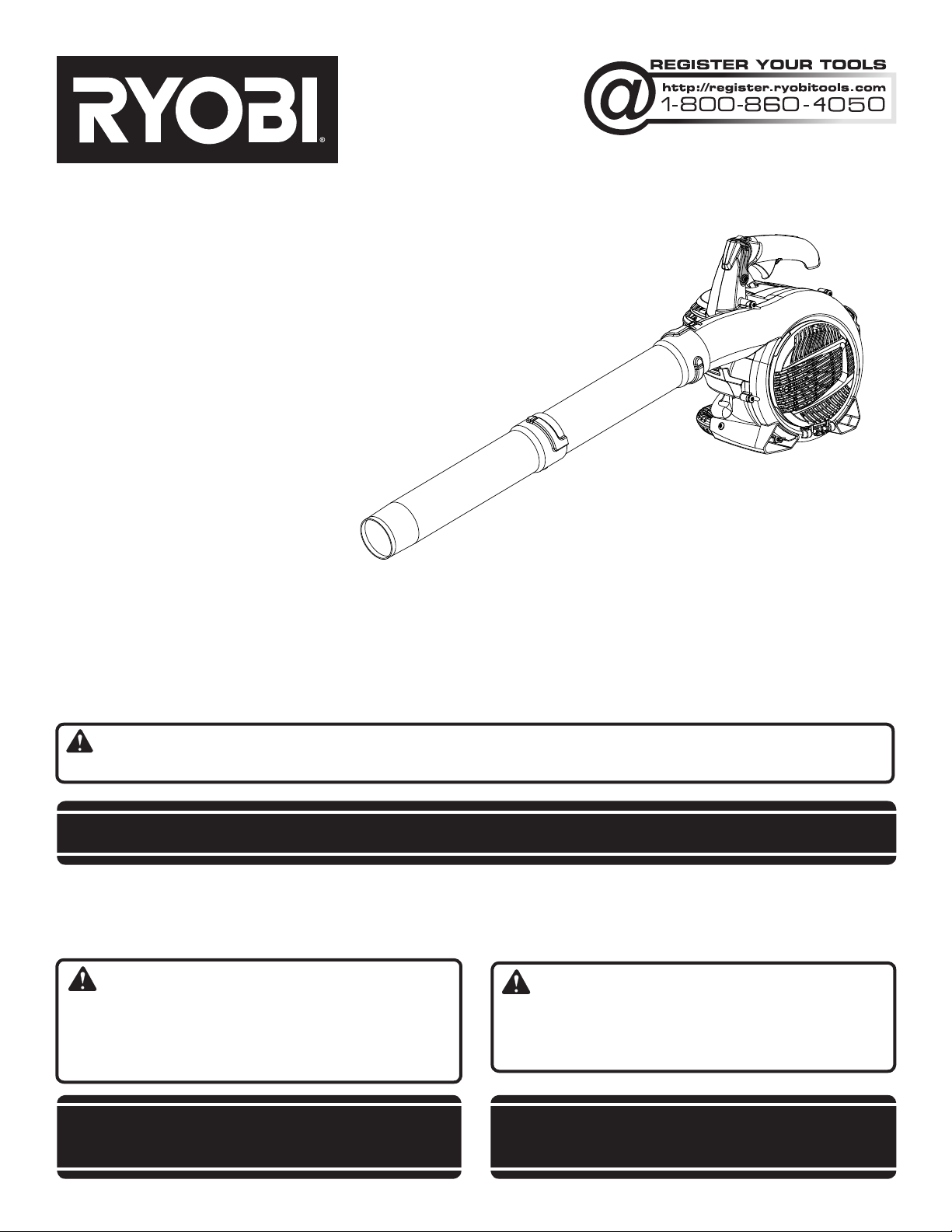
Fig. 1
B
O
C
G
E
F
A
D
A - Lower vacuum tube (tube d’aspiration inférieur, tubo inferior de la
aspiradora)
B - Shoulder strap (bandoulière, correa para el hombro)
C - Cruise control (régulateur de vitesse, control de crucero)
D - Upper vacuum tube (tube d’aspiration supérieur, tubo superior de la
aspiradora)
E - Vacuum tube screw (vis de tube d’aspiration, tornillos de los tubos
de la aspiradora)
F - Vacuum bag (sac à débris, saco de la aspiradora)
Fig. 2
Fig. 3 Fig. 5
E
B
C
A
H
N
M
P
K
J
G - Throttle trigger (gâchette d’accélérateur, gatillo del acelerador)
H - Stop switch (commutateur d’arrêt, interruptor del apagado)
I - Vacuum handle (poignée d’aspirateur , mango de la aspiradora )
J - Fuel cap (bouchon du réservoir, tapa del tanque de combustible)
K - Starter grip and rope (poignée du lanceur, mango del arrancador)
L - Primer bulb (poire d’amorçage, bomba de cebado)
M - Start lever (levier de volet de départ, palanca del anegador)
N - Upper handle (poignée supérieure, mango superior)
O - Adaptor (adaptateur, adaptador)
P - Muffler (silencieux, silenciador)
L
I
B
A
B
C
D
A
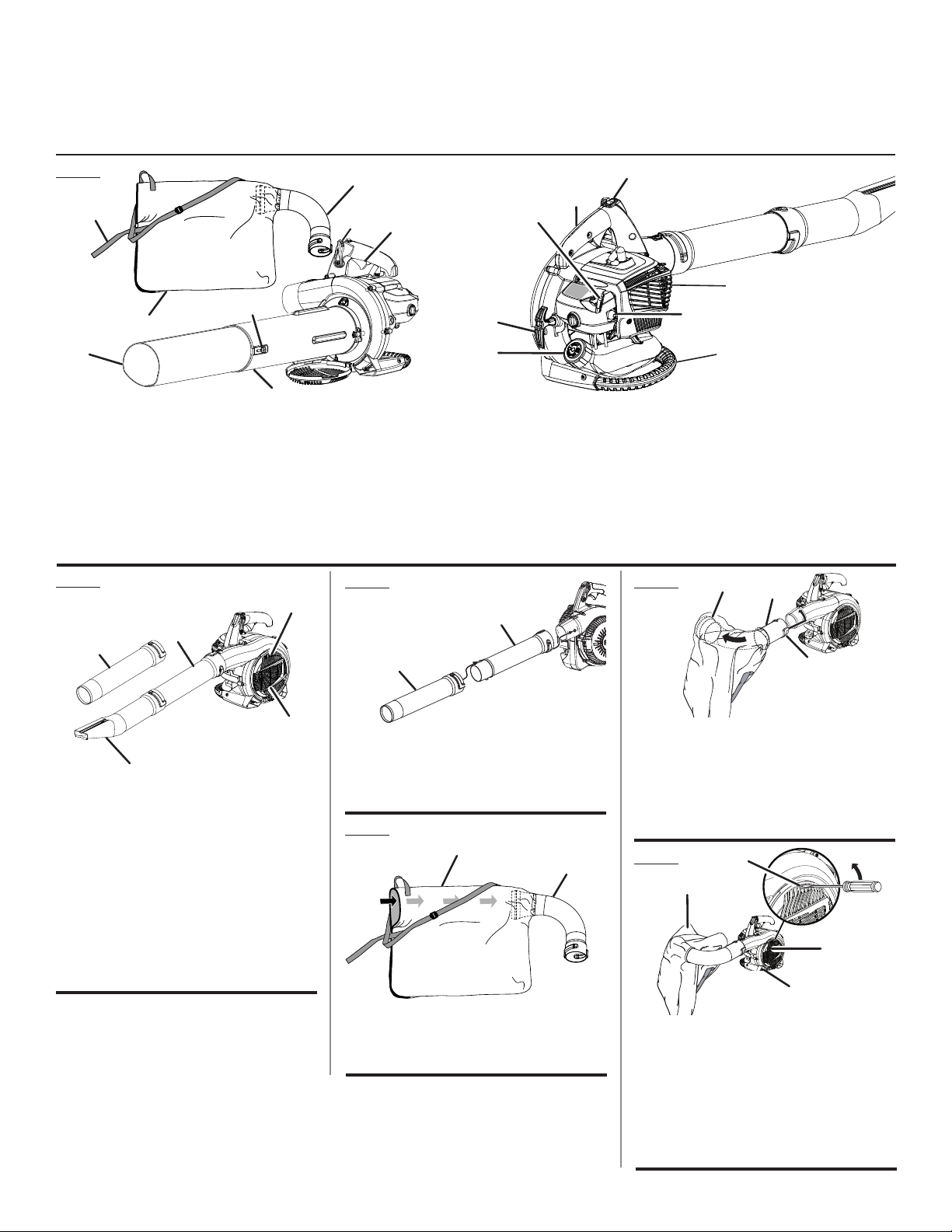
A - High velocity nozzle with wet leaf scraper
(embout haute vélocité débit avec racloir
à feuilles, boquilla de alta velocidad con
raspador para hojas húmedas)
B - Sweeper nozzle (embout éventail, boquilla
para barrer)
C - Upper blower tube (tube de soufflante
supérieur, tubo superior de la sopladora)
D - Vacuum door (volet d’entrée d’air, puerta
de la entrada)
E - Door tab (languette du volet, orejeta de la
puerta)
A - Sweeper nozzle (embout éventail, boquilla
para barrer )
B - Upper blower tube (tube de soufflante
supérieur, tubo superior de la sopladora)
Fig. 4
B
A
A - Adaptor (adaptateur, adaptador)
B - Vacuum bag (sac à débris, saco de la
aspiradora)
A - Adaptor installed in vacuum bag (adaptateur
installé dans le sac à débris, adaptador
instalado en el saco de la aspiradora)
B - Raised slot (fente en saillie, ranura realzada)
C - Raised locking tab (languette de
verrouillage en saillie, orejeta realzada de
aseguramiento)
Fig. 6
C
A
B
D
A - Vacuum bag assembly (ensemble de sac à
débris, conjunto del saco de la aspiradora)
B - Vacuum inlet door (volet d’entrée d’air,
puerta de la entrada de la aspiradora)
C - Door tab (languette du volet, orejeta de la
puerta)
D - Vacuum inlet door hinge (charnière du
volet d’aspiration, bisagra de la puerta de la
aspiradora)
i
Page 3
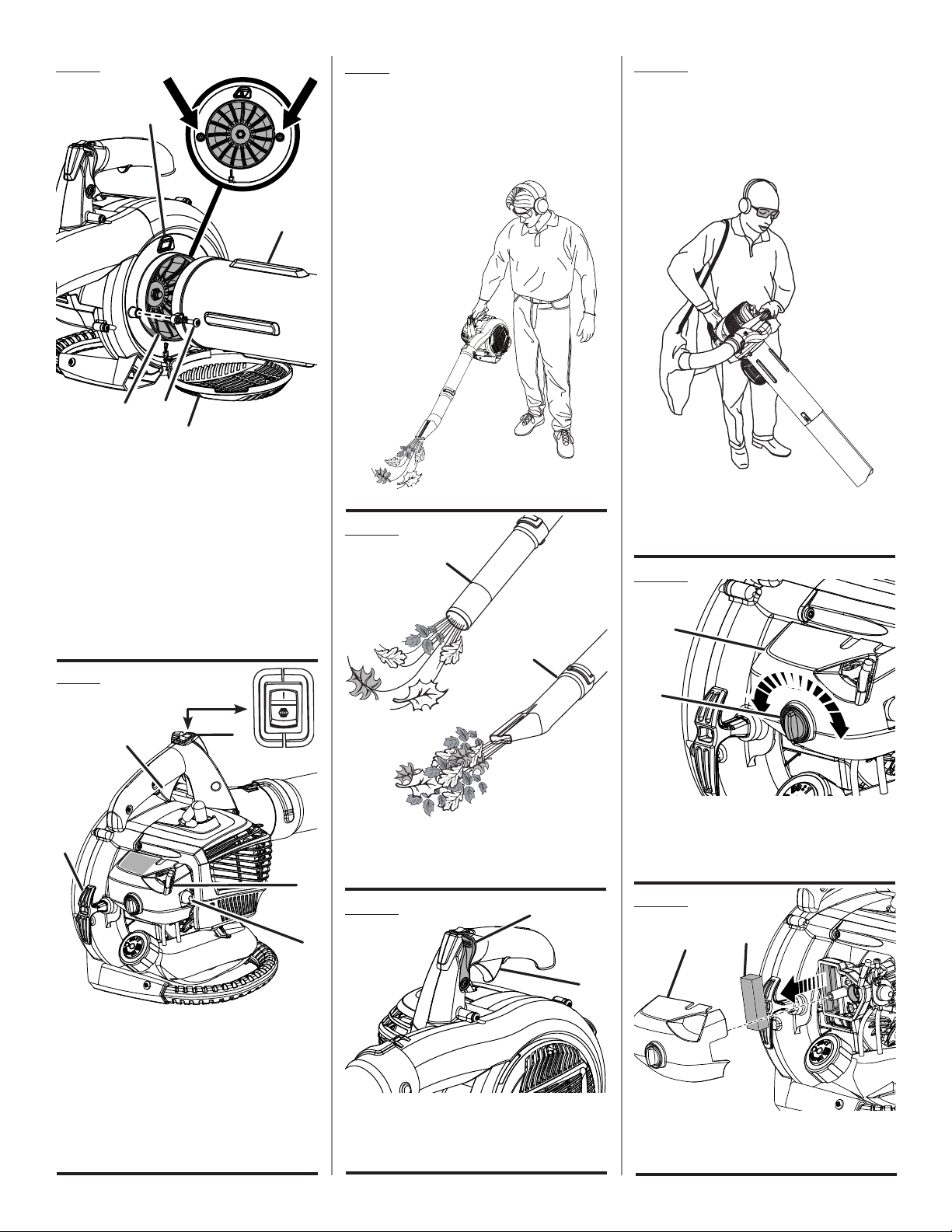
Fig. 7
F
E
A
C
D
B
A - Vacuum tube assembly (ensemble de tubes
d’aspiration, conjunto de los tubos de la
aspiradora)
B - Vacuum inlet door (volet d’entrée d’air,
puerta de la entrada de la aspiradora)
C - Screw (vis, tornillo)
D - Vacuum opening (ouverture d’aspiration,
abertura de aspiración)
E - Locking tab (languette de verrouillage,
orejetas de fijación)
F - Vacuum tube screw holes (trous de vis de
tube d’aspiration, agujeros de tornillos de
los tubos de la aspiradora)
Fig. 9
F
PROPER BLOWER OPERATING POSITION
POSITION D’UTILISATION ADÉQUATE DE LA
SOUFFLANTE
POSICIÓN DE FUNCIONAMIENTO CORRECTA
DE LA SOPLADORA
Fig. 10
A
B
Fig. 12
PROPER VACUUM OPERATING POSITION
POSITION D’UTILISATION ADÉQUATE DE
L’ASPIRATEUR
POSICIÓN DE FUNCIONAMIENTO CORRECTA
DE LA ASPIRADORA
Keep muffler away from the body (garder les
mains à l’écart des silencieux, mantenga las
manos alejadas de las silenciador)
Fig. 13
B
Fig. 8
B
E
A - Stop switch (commutateur d’arrêt,
interruptor del apagado)
B - Throttle trigger (gâchette d’accélérateur,
gatillo del acelerador)
C - Start lever (levier de volet de départ, palanca
del anegador)
D - Primer bulb (poire d’amorçage, bomba de
cebado)
E - Starter grip with rope (poignée du lanceur,
mango del arrancador)
A
C
A - Sweeper nozzle (embout éventail, boquilla
para barrer)
B - High velocity nozzle (embout haute vélocité,
boquilla de alta velocidad)
Fig. 11
D
A - Cruise control (régulateur de vitesse,
control de crucero)
B - Throttle trigger (gâchette d’accélérateur,
gatillo del acelerador)
A
A - Turn the dial to open and close (tourner
le cadran pour ouvrir et fermeture, gire el
selector para abrirla y cerrar )
B - Air filter cover (couvercle du filtre à air, tapa
de la cámara de ventilación)
A
Fig. 14
A
B
B
A - Air filter cover (couvercle du filtre à air, tapa
de la cámara de ventilación)
B - Air filter (filtre à air, filtro de aire)
ii
Page 4

TABLE OF CONTENTS
TABLE DES MATIÈRES / ÍNDICE DE CONTENIDO
Introduction ......................................................................................................................................................................2
Introduction / Introducción
General Safety Rules ........................................................................................................................................................ 3
Règles de sécurité générales / Reglas de seguridad generales
Specific Safety Rules ........................................................................................................................................................ 4
Règles de sécurité particulières / Reglas de seguridad específicas
Symbols ............................................................................................................................................................................ 5
Symboles / Símbolos
Features ............................................................................................................................................................................ 6
Caractéristiques / Características
Assembly .......................................................................................................................................................................6-7
Assemblage / Armado
Operation .....................................................................................................................................................................8-10
Utilisation / Funcionamiento
Maintenance ..............................................................................................................................................................10-11
Entretien / Mantenimiento
Troubleshooting .............................................................................................................................................................. 11
Dépannage / Solución de problemas
Warranty ....................................................................................................................................................................12-14
Garantie / Garantía
Parts Ordering and Service ...............................................................................................................................Back Page
Commande de pièces et réparation / Pedidos de piezas y servicio ......................................................... Page arrière / Pág. posterior
INTRODUCTION
INTRODUCTION / INTRODUCCIóN
This product has many features for making its use more pleasant and enjoyable. Safety, performance, and dependability
have been given top priority in the design of this product making it easy to maintain and operate.
* * *
Ce produit offre de nombreuses fonctions destinées à rendre son utilisation plus plaisante et satisfaisante. Lors de la
conception de ce produit, l’accent a été mis sur la sécurité, les performances et la fiabilité, afin d’en faire un outil facile à
utiliser et à entretenir.
* * *
Este producto ofrece numerosas características para hacer más agradable y placentero su uso. En el diseño de este producto
se ha conferido prioridad a la seguridad, el desempeño y la fiabilidad, por lo cual se facilita su manejo y mantenimiento.
2 - English
Page 5

GENERAL SAFETY RULES
WARNING:
READ AND UNDERSTAND ALL INSTRUCTIONS. Fail-
ure to follow all instructions listed below may result in
electric shock, fire and/or serious personal injury.
READ ALL INSTRUCTIONS
Do not allow children or untrained individuals to use this
unit.
Never start or run the engine inside a closed area;
breathing exhaust fumes can kill.
Wear eye protection with side shields which is marked
to comply with ANSI Z87.1 along with hearing protection
when operating this product.
Keep all bystanders, children, and pets at least 50 ft.
away.
Wear heavy long pants, long sleeves, boots, and gloves.
Do not wear loose fitting clothing, short pants, sandals,
jewelry of any kind, or go barefoot.
To reduce the risk of injury associated with objects being
drawn into rotating parts, do not wear loose clothing,
scarves, neck chains, etc.
Secure long hair so it is above shoulder level to prevent
entanglement in any rotating parts.
Do not operate this unit when you are tired, ill, or under
the influence of alcohol, drugs, or medication.
Do not operate in poor lighting.
Keep all parts of your body away from any moving parts
and all hot surfaces of the unit.
Wear a face filter mask in dusty conditions to reduce the
risk of injury associated with the inhalation of dust.
Check the work area before each use. Remove all objects
such as rocks, broken glass, nails, wire, or string which
can be thrown or become entangled in the machine.
Keep firm footing and balance. Do not overreach.
Overreaching can result in loss of balance or exposure
to hot surfaces.
Never operate the unit without a spark arrestor screen;
this screen is located inside the muffler.
Product users on United States Forest Service land,
and in some states, must comply with fire prevention
regulations. This product is equipped with a spark
arrestor; however, other user requirements may apply.
Check with the federal, state, or local authorities in your
area.
Before storing, allow the engine to cool.
Empty fuel tank into a container approved for gasoline
and restrain the unit from moving before transporting in
a vehicle.
To reduce the risk of fire and burn injury, handle fuel with
care. It is highly flammable.
Do not smoke while handling fuel.
Mix and store fuel in a container approved for gasoline.
Mix fuel outdoors where there are no sparks or flames.
Select bare ground, stop engine, and allow to cool before
refueling.
Loosen fuel cap slowly to release pressure and to keep
fuel from escaping around the cap.
Tighten the fuel cap securely after refueling.
Wipe spilled fuel from the unit. Move 30 ft. away from
refueling site before starting engine.
Never attempt to burn off spilled fuel under any
circumstances.
Use only identical manufacturer’s replacement parts and
accessories. Use of any other parts may create a hazard
or cause product damage.
Maintain the unit per maintenance instructions in this
Operator’s Manual.
Inspect the unit before each use for loose fasteners, fuel
leaks, etc. Replace damaged parts.
Do not use on a ladder, rooftop, tree, or other unstable
support. Stable footing on a solid surface enables better
control of the blower in unexpected situations.
Before cleaning, repairing, or inspecting, shut off the
engine and make certain all moving parts have stopped.
Disconnect the spark plug wire, and keep the wire away
from the plug to prevent starting.
Service on the blower/vacuum must be performed by
qualified repair personnel only. Service or maintenance
performed by unqualified personnel could result in injury
to the user or damage to the product.
3 - English
Page 6

SPECIFIC SAFETY RULES
Always hold the blower/vacuum in your right hand during
blower operation. Refer to the OPERATION instructions
later in this manual for proper position during vacuum
operation and additional information.
Never place objects inside the blower tubes.
Use only as directed in this operator’s manual.
Do not operate vacuum without vacuum bag installed;
flying debris could cause serious injury. Always close
vacuum bag completely before operating.
Rotating impeller blades can cause severe injury. Stop the
engine and ensure impeller blades have stopped rotating
before opening the vacuum door or installing/ changing
tubes. Do not put hands or any other object into the
vacuum tubes while they are installed on the unit.
Never run the unit without the proper equipment attached.
When used as a blower, always install the blower tubes.
When used as a vacuum, always install the vacuum
tubes and vacuum bag. Make sure the vacuum bag is
completely zipped when the unit is running to avoid flying
debris.
Avoid situations that could catch the vacuum bag on
fire. Do not operate near an open flame. Do not vacuum
warm ash from fireplaces, barbecue pits, brush piles, etc.
Do not vacuum discarded cigars or cigarettes unless the
cinders are completely cool.
Never place blower on any surface, except a hard, clean
surface when engine is running. Gravel, sand, and other
debris can be picked up by the air inlet and thrown at
the operator or bystanders, causing possible serious
injuries.
To reduce the risk of hearing loss associated with sound
level(s), hearing protection is required.
To reduce the risk of injury associated with contacting
rotating parts, stop the engine before installing or
removing attachments. Always disconnect the spark plug
before performing maintenance or accessing any movable
parts.
Never use blower near fires, fireplaces, hot ashes,
barbecue pits, etc., which may cause fire to spread.
Do not point the blower nozzle in the direction of people
or pets.
Never run the unit without the proper equipment attached.
Always ensure the blower tubes are installed.
FUELING
Fuel is highly flammable. Take precautions when using
to reduce the chance of serious personal injury.
Store fuel in a cool, well-ventilated area, safely away from
spark and/or flame-producing equipment.
Store fuel in containers specifically designed for this
purpose.
Only refuel outdoors and do not smoke while refueling.
Add fuel before starting the engine. Never remove the cap
of the fuel tank or add fuel while the engine is running or
when the engine is hot.
Do not smoke while handling fuel.
Mix and store fuel in a container approved for gasoline.
Mix fuel outdoors where there are no sparks or flames.
Loosen fuel cap slowly to release pressure and to keep
fuel from escaping around the cap.
Tighten the fuel cap securely after refueling.
Wipe spilled fuel from the unit. Move 30 feet away from
refueling site before starting engine.
Never attempt to burn off spilled fuel under any circum-
stances.
To reduce the risk of fire and burn injury, handle fuel with
care. It is highly flammable.
If fuel is spilled, do not attempt to start the engine but
move the machine away from the area of spillage and
avoid creating any source of ignition until fuel vapors
have dissipated.
Replace all fuel tank and container caps securely.
Empty fuel tank into a container approved for gasoline
and restrain the unit from moving before transporting in
a vehicle.
When draining the fuel tank, use an approved fuel storage
container in a well-ventilated area.
Select bare ground, stop engine, and allow to cool before
refueling.
Save these instructions. Refer to them frequently and use
them to instruct others who may use this tool. If you loan
someone this tool, loan them these instructions also.
4 - English
Page 7
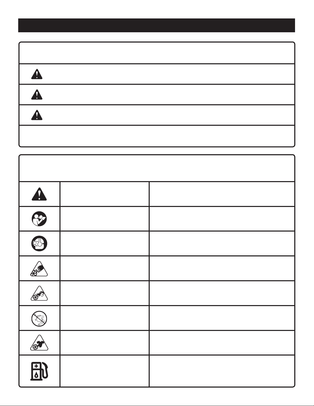
SYMBOLS
The following signal words and meanings are intended to explain the levels of risk associated with this product.
SYMBOL SIGNAL MEANING
DANGER:
WARNING:
CAUTION:
CAUTION:
Some of the following symbols may be used on this product. Please study them and learn their meaning. Proper
interpretation of these symbols will allow you to operate the product better and safer.
Indicates an imminently hazardous situation, which, if not avoided, will result
in death or serious injury.
Indicates a potentially hazardous situation, which, if not avoided, could result
in death or serious injury.
Indicates a potentially hazardous situation, which, if not avoided, may result in
minor or moderate injury.
(Without Safety Alert Symbol) Indicates a situation that may result in property
damage.
SYMBOL NAME EXPLANATION
Safety Alert Symbol Indicates a potential personal injury hazard.
Read Operator’s Manual
To reduce the risk of injury, user must read and understand
operator’s manual before using this product.
Always wear eye protection with side shields marked to
Wear Eye and Hearing Protection
Vacuum Door Do not run unit while vacuum door is unsecured.
Long Hair Risk of long hair being drawn into air inlet.
Blower Tubes Do run unit without tubes in place.
Loose Clothing Risk of loose clothing being drawn into air intake.
Gasoline and Lubricant
comply with ANSI Z87.1 as well as hearing protection when
operating this equipment.
Use unleaded gasoline intended for motor vehicle use with
an octane rating of 87 [(R + M) / 2] or higher. This product is
powered by a 2-cycle engine and requires pre-mixing gasoline
and 2-cycle lubricant.
5 - English
Page 8

FEATURES
PRODUCT SPECIFICATIONS
Engine Displacement .......................................................................................................................................................26cc
Air Velocity:
MPH ..................................................................................................................................200 (with high velocity nozzle)
CFM ........................................................................................................................................................ 400 (at housing)
Weight ......................................................................................................................................................................... 9.5 lbs.
KNOW YOUR BLOWER/VACUUM
See Figure 1.
The safe use of this product requires an understanding of
the information on the tool and in this operator’s manual as
well as a knowledge of the project you are attempting. Before
use of this product, familiarize yourself with all operating
features and safety rules.
BLOWER TUBE AND NOzzLES
The blower tube can be assembled and installed on the
blower without using any tools.
CRUISE CONTROL
The cruise control feature allows the user to operate the
blower without holding the throttle trigger. To slow the engine,
simply push the cruise control lever forward.
ENGINE
The blower has a powerful 26cc engine with sufficient power
to handle tough blowing and vacuuming jobs.
HIGH VELOCITY NOzzLE WITH WET LEAF
SCRAPER
The high velocity nozzle is great for wet sticky leaves. It
allows you to scrape wet leaves or debris while operating
the blower.
SIMPLE START™
The Simple Start™ allows for easier and quicker starting.
SWEEPER NOzzLE
The sweeper nozzle allows for more area to be covered
during blower operation.
THROTTLE TRIGGER
The blower can be operated at any speed between idle and
full throttle.
VACUUM / MULCHER
Converting the blower to a vacuum/mulcher is simple and
can be done using a flat head screwdriver.
VACUUM BAG
The vacuum bag attaches to the blower easily by using the
vacuum bag adaptor.
VACUUM HANDLE
This feature allows user to perform vacuuming duties
comfortably.
VACUUM TUBES
The vacuum tubes can be installed on the blower using a
flat head screw driver.
ASSEMBLY
UNPACKING
This product requires assembly.
Carefully remove the product and any accessories from
the box. Make sure that all items listed in the packing list
are included.
WARNING:
Do not use this product if any parts on the Packing List
are already assembled to your product when you unpack
it. Parts on this list are not assembled to the product by
the manufacturer and require customer installation. Use
of a product that may have been improperly assembled
could result in serious personal injury.
Inspect the product carefully to make sure no breakage
or damage occurred during shipping.
PACKING LIST
Blower
Upper Blower Tube
Sweeper Nozzle
High Velocity Nozzle
Upper and Lower Vacuum Tubes
Vacuum Tube Screws (2)
Vacuum Bag
Vacuum Bag Adaptor
2-Cycle Engine Lubricant
Operator’s Manual
NOTE: Read and remove all hang tags and store with your
operator’s manual.
6 - English
Do not discard the packing material until you have care-
fully inspected and satisfactorily operated the product.
If any parts are damaged or missing, please call
1-800-860-4050 for assistance.
Page 9
ASSEMBLY
WARNING:
If any parts are damaged or missing do not operate this
product until the parts are replaced. Use of the product
with damaged or missing parts could result in possible
serious personal injury.
WARNING:
Do not attempt to modify this product or create accessories not recommended for use with this product. Any
such alteration or modification is misuse and could result
in a hazardous condition leading to possible serious
personal injury.
WARNING:
To prevent accidental starting that could cause serious
personal injury, always disconnect the engine spark plug
wire from the spark plug when assembling parts.
ASSEMBLING THE BLOWER TUBES
See Figures 2 - 3.
Align raised tabs on blower housing outlet to the slots
on upper tube; slide together and tighten securely by
twisting. Check tightness after initial use and retighten if
needed.
Attach desired nozzle (high velocity nozzle or sweeper
nozzle) to upper blower tube by aligning raised tabs on
upper blower tube; slide together and tighten securely by
twisting. Check tightness after initial use and retighten if
needed.
To remove the tubes, rotate the tubes to unlock them and
remove from the blower housing outlet.
INSTALLING THE VACUUM BAG
See Figures 4 - 5.
Remove the nozzle and upper blower tube from the
blower by twisting and removing from blower housing
outlet.
Unzip the vacuum bag and place the adaptor inside as
shown. Push the vacuum bag adaptor through the opening opposite the zipper. The wider end of the adaptor will
remain on the inside of the vacuum bag when installed
properly.
Align the raised slots on the vacuum bag adaptor with the
raised locking tabs on the blower housing outlet; push the
bag adaptor onto the housing. Twist to lock into place.
Rotate the vacuum bag until the shoulder strap is upright.
Make sure the vacuum bag is zipped and closed before
starting the unit.
INSTALLING THE VACUUM TUBES
See Figures 6 - 7.
WARNING:
Contact with rotating impeller blades could result in serious personal injury. Always stop the engine and ensure
impeller blades have stopped rotating before opening
the vacuum door or installing/changing tubes. Do not put
hands or any other object into the vacuum tubes while
they are installed on the unit.
To install the vacuum tubes:
Secure the upper and lower vacuum tubes together by
aligning the raised locking tabs with the raised slots.
Tap tube assembly on ground until the screw holes in
lower tube are in the raised slot of the upper tube. Secure
with supplied screws (see figure 1).
Depress door tab using a flathead screwdriver and open
vacuum inlet door.
Align tabs on housing with tube assembly.
Turning clockwise, tighten screws on upper vacuum tube
to secure to blower housing.
To remove the vacuum tubes:
Loosen screws of the upper vacuum tube by turning
counterclockwise.
Remove the vacuum tube assembly from the blower
housing.
Close the vacuum inlet cover door securely.
7 - English
Page 10
OPERATION
WARNING:
Do not allow familiarity with this product to make you
careless. Remember that a careless fraction of a second is
sufficient to inflict serious injury.
WARNING:
Always wear eye protection with side shields marked to
comply with ANSI Z87.1, along with hearing protection.
Failure to do so could result in objects being thrown into
your eyes and other possible serious injuries.
APPLICATIONS
You may use this product for the purposes listed below:
Clearing leaves and other debris from your lawn
Keeping decks and driveways free from leaves and pine
needles
Vacuuming leaves from your lawn
MIXING THE FUEL
This product is powered by a 2-cycle engine and requires
premixing gasoline and 2-cycle oil. The mixture should be
at a 50:1 ratio.
NOTE: We recommend you use ONLY Ryobi (exact mix)
your product.
To mix the fuel:
Use a clean container that is approved for use with gaso-
line.
Mix the 2-cycle engine oil with unleaded gasoline in the
container, according to the instructions on the oil package.
This engine is certified to operate on unleaded gasoline
intended for automotive use with an octane rating of 87
[(R + M) / 2] or higher. Do not use automotive oil or 2-cycle
outboard oil.
NOTE: Most fuel mixture will stay fresh up to 30 days. DO
NOT mix quantities larger than usable in a 30 day period.
FILLING THE TANK
Clean the surface around the fuel cap to prevent con-
tamination.
Loosen the fuel cap slowly by turning counterclock-
wise.
Pour the fuel mixture carefully into the tank.
Clean and inspect the fuel cap gasket before replacing
the fuel cap.
Replace the fuel cap and tighten it by turning it clock-
wise.
Wipe spilled fuel from the product.
Move at least 30 ft. away from refueling area before start-
ing the product.
NOTE: It is normal for smoke to be emitted from a new
engine during first use.
WARNING:
Always shut off engine before fueling. Never add fuel to
a machine with a running or hot engine. Move at least
30 ft. from refueling site before starting engine. Do not
smoke and stay away from open flames and sparks.
Failure to safely handle fuel could result in serious personal injury.
OXYGENATED FUELS
DO N OT U SE E85 FUEL. IT WILL VOID YOUR
WARRANTY.
NOTE: Fuel system damage or performance problems
resulting from the use of an oxygenated fuel containing more
than the percentages of oxygenates stated previously are
not covered under warranty.
Ethanol. Gasoline containing up to 10% ethanol by
volume (commonly referred to as E10) or 15% ethanol by
volume (commonly referred to as E15) are acceptable.
Do not use E85 fuel.
STARTING AND STOPPING
See Figure 8.
2-CYCLE FUEL / OIL MIX (50:1)
GASOLINE OIL
1 gallon (US) 2.6 oz.
1 liter 20 cc (20 ml)
To start a cold engine:
DO NOT squeeze the throttle trigger until the engine starts
and runs.
Lay the blower/vacuum on a flat, bare surface.
PRIME - Press the primer bulb 7 times.
SET the start lever to the START position.
PULL the starter grip with rope until the engine starts.
NOTE: Squeezing and releasing the throttle trigger releases
the start lever to the RUN position.
8 - English
Page 11
OPERATION
To start a warm engine:
PULL the starter grip with rope until the engine starts.
To stop the engine:
Press and hold the STOP switch in the stop “ ” position
until the engine stops.
OPERATING THE BLOWER
See Figures 9 - 10.
WARNING:
Never run the unit without the blower tubes installed or
the vacuum door securely closed. Use of an improperly
assembled unit could result in serious personal injury.
Start the blower. Refer to Starting and Stopping earlier
in this manual. Hold the blower with the upper handle in
your right hand.
WARNING:
Always hold the blower away from your body with the
handle in your right hand when operating as a blower,
keeping clearance between your body and the product.
The muffler side of the blower should be away from your
body. Any contact with the housing can result in burns
and/or other serious personal injury.
Watch out for children, pets, open windows, or freshly
washed cars, and blow debris safely away.
Hold blower, as shown in Figure 9, so the air stream can
work close to the ground.
After using blowers or other equipment, CLEAN UP!
Dispose of debris properly.
Use the sweeper nozzle for the everyday blowing opera-
tion. This nozzle allows for more area to be covered during
the blowing operation.
The high velocity nozzle is specifically designed for wet
sticky leaves. It allows you to scrape wet leaves or debris
while operating the blower.
CRUISE CONTROL
See Figure 11.
The cruise control can be used to operate the blower without
holding the throttle trigger.
To engage the cruise control:
Pull cruise control lever back towards user, and stop at
the desired throttle setting.
To release the cruise control, push cruise control lever
all the way towards the front of unit.
VACUUM OPERATION
See Figure 12.
WARNING:
Do not place blower on top of or near loose debris or
gravel. Debris may be sucked into blower intake vent
resulting in possible damage to the unit and could result
in serious personal injury.
To keep from scattering debris, blow around the outer
edges of a debris pile. Never blow directly into the center
of a pile.
Operate power equipment at reasonable hours only - not
early in the morning or late at night when people might
be disturbed. Comply with the times listed in local ordinances.
To reduce sound levels, limit the number of pieces of
equipment used at any one time.
Conserve water by using power blowers instead of hoses
for many lawn and garden applications, including areas
such as gutters, screens, patios, grills, porches, and
gardens.
Operate blower at the lowest possible throttle speed to
do the job.
Check your equipment before operation, especially the
muffler, air intakes, and air filters.
Use rakes and brooms to loosen debris before blowing.
In dusty conditions, slightly dampen surfaces when water
is available.
Never run the unit without the vacuum tubes and vacuum
bag installed. Use of an improperly assembled unit could
result in serious personal injury.
Keep the muffler and all hot surfaces of the blower/
vacuum away from your body. Failure to do so could
result in possible serious personal injury.
9 - English
WARNING:
WARNING:
Install the vacuum tubes and the bag. Refer to the
ASSEMBLY section earlier in this manual.
Start the blower. Refer to Starting and Stopping earlier
in this manual.
Place the vacuum bag strap over your right shoulder.
Hold the upper handle in your left hand and the vacuum
handle in your right hand.
Move the blower/vacuum from side to side along outer
edge of the debris. To avoid clogging, do not place the
vacuum tube directly into the debris pile.
Hold the engine higher than the inlet end of the vacuum
tube.
Always point vacuum tube downhill when working on a
hillside.
Page 12
OPERATION
To avoid serious injury to the operator or damage to the
unit, do not pick up rocks, metal, broken glass, bottles,
or other similar objects.
If the vacuum tubes should clog, stop the engine , ensure
impeller blades have stopped spinning, and disconnect
the spark plug wire before cleaning out the obstruction.
MAINTENANCE
WARNING:
When servicing, use only identical replacement parts.
Use of any other parts may create a hazard or cause
product damage.
WARNING:
Always wear eye protection with side shields marked to
comply with ANSI Z87.1, along with hearing protection.
Failure to do so could result in objects being thrown into
your eyes and other possible serious injuries.
WARNING:
Before inspecting, cleaning, or servicing the machine,
shut off engine, wait for all moving parts to stop, and
disconnect spark plug wire and move it away from spark
plug. Failure to follow these instructions can result in
serious personal injury or property damage.
GENERAL MAINTENANCE
Avoid using solvents when cleaning plastic parts. Most
plastics are susceptible to damage from various types of
commercial solvents and may be damaged by their use. Use
clean cloths to remove dirt, dust, lubricant, grease, etc.
WARNING:
Do not at any time let brake fluids, gasoline, petroleumbased products, penetrating lubricants, etc., come in contact with plastic parts. Chemicals can damage, weaken or
destroy plastic which may result in serious personal
injury.
Remove the vacuum tubes and clear the debris from the
blower fan housing. Remove the bag and clear the tube.
A small rod or stick may be required to clear the entire
tube length. Ensure that all debris has been cleared before
reassembling the vacuum tubes.
You can often make adjustments and repairs described here.
For other repairs, have the blower/vacuum serviced by an
authorized service dealer.
CLEANING THE AIR FILTER
See Figure 13 - 14.
For proper performance and long life, keep air filter clean.
Remove the air filter cover by turning the dial counter-
clockwise while gently pulling on the cover.
Rinse filter with clean water.
Gently squeeze filter until excess water is removed.
Replace filter.
Place the air filter cover back on the unit. Turn dial clock-
wise until cover is secure.
CLEANING THE EXHAUST PORT, MUFFLER
AND SPARK ARRESTOR
NOTE: Depending on the type of fuel used, the type and
amount of lubricant used, and/or your operating conditions, the
exhaust port, muffler, and/or spark arrestor screen may become blocked with carbon deposits. If you notice a power
loss with your gas powered tool, you may need to remove
these deposits to restore performance. We highly recommend that only qualified service technicians perform this
service.
The spark arrestor must be cleaned or replaced every 50
hours or yearly to ensure proper performance of your product. Spark arrestors may be in different locations depending
on the model purchased. Please contact your nearest service
dealer for the location of the spark arrestor for your model.
WARNING:
Never run the blower without the spark arrestor in place.
Failure to do so could result in a fire that could cause
serious personal injury.
10 - English
Page 13

MAINTENANCE
VACUUM BAG
A dirty bag will reduce performance. To clean the bag, turn it
inside out and shake. Wash the bag in soapy water at least
once a year. To obtain a replacement bag, see How to Order
Replacement Parts on the back page of this manual.
FUEL CAP
WARNING:
Check for fuel leaks. A leaking fuel cap is a fire hazard
and must be replaced immediately. If you find any leaks,
correct the problem before using the product. Failure
to do so could result in a fire that could cause serious
personal injury.
The fuel cap contains a non-serviceable filter and a
check valve. A clogged fuel filter will cause poor engine
performance. If performance improves when the fuel cap
is loosened, check valve may be faulty or filter clogged.
Replace fuel cap if required.
SPARK PLUG REPLACEMENT
This engine uses a Ryobi AC00160, Champion RCJ-6Y or
NGK BPMR7A spark plug with .025 in. electrode gap. Use
an exact replacement and replace annually.
STORING THE PRODUCT
Clean all foreign material from the product. Store idle unit
indoors in a dry, well-ventilated area that is inaccessible
to children. Keep away from corrosive agents such as
garden chemicals and de-icing salts.
Abide by all ISO and local regulations for the safe storage
and handling of gasoline.
When storing 1 month or longer:
Drain all fuel from tank into a container approved for
gasoline. Run engine until it stops.
TROUBLESHOOTING
IF THESE SOLUTIONS DO NOT SOLVE THE PROBLEM, CONTACT YOUR AUTHORIzED SERVICING DEALER.
PROBLEM CAUSE REMEDY
Engine fails to start. No fuel in tank.
Spark plug shorted or fouled.
Spark plug is broken. (cracked
porcelain or electrodes broken)
Ignition lead wire shorted, broken, or
disconnected from spark plug.
Ignition inoperative.
Engine hard to start. Water in gasoline or stale fuel mixture.
Too much lubricant in fuel mixture.
Engine is under or over choked.
Weak spark at spark plug.
Engine lacks power. Air filter clogged. Clean air filter. Refer to Cleaning the
Engine overheats. Insufficient lubricant in fuel mixture. Mix fuel as described in starting
Fill tank.
Replace spark plug.
Replace spark plug.
Replace lead wire or attach to spark
plug.
Contact authorized service center.
Drain entire system and refill with fresh
fuel.
Drain and refill with correct mixture.
Adjust choke as necessary.
Contact authorized service center.
Air Filter Screen earlier in this manual.
instructions.
11 - English
Page 14

WARRANTY
LIMITED WARRANTY STATEMENT
Techtronic Industries North America, Inc., warrants to the
original retail purchaser that this RYOBI® brand outdoor
product is free from defect in material and workmanship
and agrees to repair or replace, at Techtronic Industries
North America, Inc.’s, discretion, any defective product
free of charge within these time periods from the date of
purchase.
Three years if the product is used for personal, family
or household use;
90 days, if used for any other purpose, such as
commercial or rental.
This warranty extends to the original retail purchaser
only and commences on the date of the original retail
purchase.
Any part of this product found in the reasonable judgment
of Techtronic Industries North America, Inc. to be defective
in material or workmanship will be repaired or replaced
without charge for parts and labor by an authorized service
center for RYOBI® brand outdoor products (Authorized
Ryobi Service Center).
The product, including any defective part, must be returned
to an authorized Ryobi service center within the warranty
period. The expense of delivering the product to the service
center for warranty work and the expense of returning it
back to the owner after repair or replacement will be paid
by the owner. Techtronic Industries North America, Inc.’s,
responsibility in respect to claims is limited to making the
required repairs or replacements and no claim of breach of
warranty shall be cause for cancellation or rescission of the
contract of sale of any RYOBI® brand outdoor product. Proof
of purchase will be required by the dealer to substantiate
any warranty claim. All warranty work must be performed
by an authorized service dealer.
This warranty is limited to ninety (90) days from the date
of original retail purchase for any RYOBI® brand outdoor
product that is used for rental or commercial purposes, or
any other income-producing purpose.
This warranty does not cover any product that has been
subject to misuse, neglect, negligence, or accident, or that
has been operated in any way contrary to the operating
instructions as specified in this operator’s manual. This
warranty does not apply to any damage to the product that
is the result of improper maintenance or to any product
that has been altered or modified. The warranty does not
extend to repairs made necessary by normal wear or by the
use of parts or accessories which are either incompatible
with the RYOBI® brand outdoor product or adversely affect
its operation, performance, or durability. In addition, this
warranty does not cover:
A. Tune-ups – Spark Plugs, Carburetor, Carburetor
Adjustments, Ignition, Filters
B. Wear items – Bump Knobs, Outer Spools, Cutting
Lines, Inner Reels, Starter Pulleys, Starter Ropes, Drive
Belts, Tines, Felt Washers, Hitch Pins, Mulching Blades,
Blower Fans, Blower and Vacuum Tubes, Vacuum Bag
and Straps, Guide Bars, Saw Chains
Techtronic Industries North America, Inc., reserves the
right to change or improve the design of any RYOBI® brand
outdoor product without assuming any obligation to modify
any product previously manufactured.
ALL IMPLIED WARRANTIES ARE LIMITED IN DURATION
TO THE STATED WARRANTY PERIOD. ACCORDINGLY,
ANY SUCH IMPLIED WARRANTIES INCLUDING
MERCHANTABILITY, FITNESS FOR A PARTICULAR
PURPOSE, OR OTHERWISE, ARE DISCLAIMED IN
THEIR ENTIRETY AFTER THE EXPIRATION OF THE
APPROPRIATE TWO-YEAR, ONE-YEAR, OR NINETYDAY WARRANTY PERIOD. TECHTRONIC INDUSTRIES
NORTH AMERICA, INC.’S, OBLIGATION UNDER THIS
WARRANTY IS STRICTLY AND EXCLUSIVELY LIMITED TO
THE REPAIR OR REPLACEMENT OF DEFECTIVE PARTS
AND TECHTRONIC INDUSTRIES NORTH AMERICA,
INC., DOES NOT ASSUME OR AUTHORIZE ANYONE
TO ASSUME FOR THEM ANY OTHER OBLIGATION.
SOME STATES DO NOT ALLOW LIMITATIONS ON HOW
LONG AN IMPLIED WARRANTY LASTS, SO THE ABOVE
LIMITATION MAY NOT APPLY TO YOU. TECHTRONIC
INDUSTRIES NORTH AMERICA, INC., ASSUMES NO
RESPONSIBILITY FOR INCIDENTAL, CONSEQUENTIAL,
OR OTHER DAMAGES INCLUDING, BUT NOT LIMITED
TO, EXPENSE OF RETURNING THE PRODUCT TO AN
AUTHORIZED RYOBI SERVICE CENTER AND EXPENSE
OF DELIVERING IT BACK TO THE OWNER, MECHANIC’S
TRAVEL TIME, TELEPHONE OR TELEGRAM CHARGES,
RENTAL OF A LIKE PRODUCT DURING THE TIME
WARRANTY SERVICE IS BEING PERFORMED, TRAVEL,
LOSS OR DAMAGE TO PERSONAL PROPERTY, LOSS
OF REVENUE, LOSS OF USE OF THE PRODUCT,
LOSS OF TIME, OR INCONVENIENCE. SOME STATES
DO NOT ALLOW THE EXCLUSION OR LIMITATION OF
INCIDENTAL OR CONSEQUENTIAL DAMAGES, SO THE
ABOVE LIMITATION OR EXCLUSION MAY NOT APPLY
TO YOU.
This warranty gives you specific legal rights, and you may
also have other rights which vary from state to state.
This warranty applies to all RYOBI® brand outdoor products
manufactured by or for Techtronic Industries North America,
Inc., and sold in the United States and Canada.
To locate your nearest Authorized Ryobi Service Center,
dial 1-800-860-4050.
12 - English
Page 15

WARRANTY
THE FOLLOWING CALIFORNIA AIR RESOURCES BOARD (CARB) STATEMENT ONLY APPLIES TO MODEL NUMBERS REqUIRED TO MEET THE CARB REqUIREMENTS.
TECHTRONIC INDUSTRIES NORTH AMERICA, INC., LIMITED WARRANTY STATEMENT FOR FEDERAL
AND CALIFORNIA EMISSION CONTROL SYSTEMS NON-ROAD AND SMALL OFF-ROAD ENGINES
YOUR WARRANTY RIGHTS AND OBLIGATIONS
The U.S. Environmental Protection Agency (EPA), the California Air Resources Board
(CARB), and Techtronic Industries North America, Inc., are pleased to explain the
Emissions Control System Warranty on your 2009 model year non-road or small offroad engine. In California, new equipment that uses small off-road engines must be
designed, built, and equipped to meet the state’s stringent anti-smog standards. In
other states, new 2000 and later model year non-road engines must be designed,
built, and equipped at the time of sale to meet the U.S. EPA regulations for small
non-road engines. The non-road engine must be free from defects in materials and
workmanship which cause it to fail to conform with U.S. EPA standards for the first
two years of engine use from the date of sale to the ultimate purchaser. Techtronic
Industries North America, Inc., must warrant the emission control system on your
non-road or small off-road engine for the period of time listed above provided there
has been no abuse, neglect, or improper maintenance of your non-road or small
off-road engine.
Your emission control system may include parts such as the carburetor or fuel injection
system, the ignition system, catalytic converters, fuel tanks, valves, filters, clamps,
connectors, and other associated components. Also included may be hoses, belts
and connectors, and other emission-related assemblies.
Where a warrantable condition exists, Techtronic Industries North America, Inc., will
repair your non-road or small off-road engine at no cost to you, including diagnosis, parts, and labor performed at an authorized service center for RYOBI® brand
outdoor products.
MANUFACTURER’S WARRANTY COVERAGE:
This product’s emissions control system is warranted for two years. If any emissionrelated part on your engine is defective, the part will be repaired or replaced by
Techtronic Industries North America, Inc., free of charge.
OWNER’S WARRANTY RESPONSIBILITIES
(a) As the non-road or small off-road engine owner, you are responsible for
the performance of the required maintenance listed in your operator’s manual.
Techtronic Industries North America, Inc., recommends that you retain all receipts covering maintenance on your non-road or small off-road engine, but
Techtronic Industries North America, Inc., cannot deny warranty solely for the
lack of receipts or for your failure to ensure the performance of all scheduled
maintenance. Any replacement part or service that is equivalent in performance
and durability may be used in non-warranty maintenance or repairs, and shall
not reduce the warranty obligations of Techtronic Industries North America, Inc.
(b) As the non-road or small off-road engine owner, you should be aware, however,
that Techtronic Industries North America, Inc., may deny you warranty coverage if
your non-road or small off-road engine or a part has failed due to abuse, neglect,
improper maintenance, or unapproved modifications.
(c) You are responsible for presenting your non-road or small off-road engine to an
authorized service dealer as soon as a problem exists. The warranty repairs should
be completed in a reasonable amount of time, not to exceed 30 days.
If you have any questions regarding your warranty rights and responsibilities, you
should contact a Techtronic Industries North America, Inc., Customer Representative at 1-800-860-4050.
DEFECT WARRANTY COVERAGE REqUIREMENTS:
(a) The warranty period begins on the date the engine or equipment is delivered to
an ultimate purchaser.
(b) General Emissions Warranty Coverage. Techtronic Industries North America,
Inc., warrants to the ultimate purchaser and each subsequent purchaser that your
non-road or small off-road engine is designed, built, and equipped at the time of sale
to conform with all applicable regulations adopted by the California Air Resources
Board or the United States Environmental Protection Agency; and that it is free from
defects in materials and workmanship which cause the engine to fail to conform with
applicable regulations for a period of two years from the date the non-road or small
off-road engine is purchased by the initial purchaser.
(c) The warranty on emissions-related parts will be interpreted as follows: Any
warranted part that is not scheduled for replacement as required in the Emissions
Maintenance Schedule and Warranty Parts List set forth below is warranted for two
years. If any such part (including any part that is scheduled only for regular inspection)
fails during the period of warranty coverage, it will be repaired or replaced at any
RYOBI® Authorized Service Center at no charge. Any such part repaired or replaced
under warranty will be warranted for the remaining warranty period. A statement to
the effect of “repair or replace as necessary” would not reduce the period of warranty coverage. Any warranted part that is scheduled for replacement as required
maintenance in the Emissions Maintenance Schedule and Warranty Parts List is
warranted for the period of time prior to the first scheduled replacement point for
that part. Any such part repaired or replaced under warranty is warranted for the
remainder of the period prior to the first scheduled replacement point, and will be
repaired or replaced at any RYOBI® Authorized Service Center for no charge until
that replacement point is reached.
Techtronic Industries North America, Inc., shall remedy warranty defects at any
authorized RYOBI® Authorized Service Center, including any distribution center
that may be franchised to service the subject engines. Any diagnostic work done
at a RYOBI® Authorized Service Center shall be free of charge to the owner if such
work determines that a warranted part is defective. Any manufacturer-approved or
equivalent replacement part may be used for any warranty maintenance or repairs
on emission-related parts, and must be provided free of charge to the owner if the
part is still under warranty. Techtronic Industries North America, Inc., is liable for
damages to other engine components caused by the failure of a warranted part
still under warranty.
Add-on or modified parts that are not exempted by the California Air Resource Board
may not be used. The use of any non-exempted add-on or modified parts will be
grounds for disallowing a warranty claim. Techtronic Industries North America, Inc.,
will not be liable to warrant failures of warranted parts caused by the use of a nonexempted add-on or modified part.
The California Air Resources Board’s Emission Warranty Parts List specifically defines
the emission-related warranted parts. (EPA’s regulations do not include a parts list,
but the EPA considers emission-related warranted parts to include all the parts listed
below.) Techtronic Industries North America, Inc., will provide any documents that
describe its warranty procedures or policies within five days upon request by the
California Air Resources Board.
EMISSIONS PARTS LIST
Emissions parts vary from product to product. Your emissions control system warranty
applies to any of the following components that may be included on your product:
(1) Fuel Metering System
(i) Carburetor and internal parts (and/or pressure regulator or fuel injection
system).
(ii) Air/fuel ratio feedback and control system.
(iii) Cold start enrichment system.
(iv) Fuel Tank.
(2) Air Induction System
(i) Controlled hot air intake system.
(ii) Intake manifold.
(iii) Air filter.
(3) Ignition System
(i) Spark Plugs.
(ii) Magneto or electronic ignition system.
(iii) Spark advance/retard system.
(4) Exhaust Gas Recirculation (EGR) System
(i) EGR valve body and carburetor spacer, if applicable.
(ii) EGR rate feedback and control system.
(5) Air Injection System
(i) Air pump or pulse valve.
(ii) Valves affecting distribution of flow.
(iii) Distribution manifold.
(6) Catalyst or Thermal Reactor System
(i) Catalytic converter.
(ii) Thermal reactor.
(iii) Exhaust manifold.
(7) Particulate Controls
(i) Traps, filters, precipitators, and any other device used to capture particulate
emissions.
(8) Miscellaneous Items Used in Above Systems
(i) Electronic controls.
(ii) Vacuum, temperature, and time sensitive valves and switches.
(iii) Hoses, belts, connectors, and assemblies.
Techtronic Industries North America, Inc., will furnish with each new engine written
instructions for its maintenance and use by the owner.
The Emissions Compliance Period referred to on the Emissions Compliance label
indicates the number of operating hours for which the engine has been shown to
meet Federal emission requirements. Category C=50 hours, B=125 hours, and
A=300 hours.
13 - English
Page 16

WARRANTY
THIS PRODUCT WAS MANUFACTURED WITH A CATALYST MUFFLER
Congratulations! You have made an investment toward protecting the environment. In order to maintain this product’s
original emission level, please refer to the maintenance section below.
EMISSIONS MAINTENANCE SCHEDULE AND WARRANTED PARTS LIST
Emissions Parts Inspect Before Clean Every Replace Clean Every Replace Every
Each Use 5 Hours Every 25 Hours 25 Hours 50 Hours
or Yearly or Yearly
CATALYTIC MUFFLER ASSEMBLY ................................................................................................................... X
AIR FILTER ASSY
includes:
Filter Screen .....................................................X
SPARK SCREEN ................................................................................................................................................X
CARBURETOR ASSY
includes:
Heat Dam ........................ X
Gaskets ........................... X
FUEL TANK ASSY
includes:
Fuel Lines ........................ X
Fuel Cap .......................... X
Fuel Filter
IGNITION ASSY
includes:
Spark Plug ........................................................................................ X
ALL EMISSIONS-RELATED PARTS ARE WARRANTED FOR TWO YEARS OR FOR THE PERIOD OF TIME PRIOR TO
THE PARTS FIRST SCHEDULED REPLACEMENT WHICHEVER COMES FIRST.
CALL US FIRST
For any questions about operating or maintaining your product,
call the Ryobi® Help Line!
Your product has been fully tested prior to shipment to ensure
your complete satisfaction.
14 - English
Page 17

RÈGLES DE SÉCURITÉ GÉNÉRALES
AVERTISSEMENT :
LIRE ET VEILLER À BIEN COMPRENDRE TOUTES LES
INSTRUCTIONS. Le non respect de toutes les instruc-
tions ci-dessous peut entraîner un choc électrique, un
incendie et / ou des blessures graves.
CONSERVER CES INSTRUCTIONS
Ne pas laisser des enfants ou personnes n’ayant pas reçu
une formation adéquate utiliser cet outil.
Ne jamais lancer ou faire tourner le moteur dans un endroit
clos. Les gaz d’échappement peuvent être mortels.
Porter une protection oculaire avec écrans latéraux
certifiée conforme à la norme ANSI Z87.1, ainsi qu’une
protection auditive lors de l’utilisation de ce produit.
Garder tous les badauds, enfants et animaux domestiques
à une distance d’au moins 15 m (50 pi).
Porter des pantalons longs, manches longues, des
chaussures de travail et des gants épais. Ne pas porter
de vêtements amples, shorts, sandales, bijoux quels qu’ils
soient et ne pas travailler pieds nus.
Pour réduire les risques de happement par les pièces en
mouvement, ne pas porter de vêtements amples, foulards,
colliers, etc.
Attacher les cheveux longs pour les maintenir au-dessus
des épaules, afin qu’ils ne se prennent pas dans les pièces
en rotation.
Ne pas utiliser cet outil en état de fatigue, si l’on est
souffrant ou sous l’influence de l’alcool, de drogues ou
de médicaments.
Ne pas travailler sous un éclairage insuffisant.
Garder toutes les parties du corps à l’écart des pièces
en mouvement et des paries brûlantes de l’outil.
Porter un masque facial filtrant dans les milieux
poussiéreux afin de réduire le risque de lésions lié à
l’inhalation de poussière.
Examiner la zone de travail avant chaque utilisation. La
débarrasser de tous les objets tels que cailloux, verre
brisé, clous, fils métalliques, cordes, etc. risquant d’être
projetés ou de se prendre dans la machine.
Se tenir bien campé et en équilibre. Ne pas travailler
hors de portée. Le travail hors de portée risque de faire
perdre l’équilibre ou de causer un contact avec les
pièces brûlantes.
Ne jamais utiliser l’outil sans le pare-étincelles, qui se
trouve dans le silencieux.
Les produits utilisés sur les territoires des services
forestiers des États-Unis et de certains états doivent être
conformes aux réglementations de lutte contre l’incendie.
Cet outil est doté d’un pare-étincelles, toutefois, d’autres
dispositifs peuvent être requis. Consulter les autorités
locales et gouvernementales.
Laisser le moteur refroidir avant de remiser l’outil.
Vider le réservoir de carburant dans un contenant
approuvé pour l’essence et immobiliser l’unité avant de
la transporter dans un véhicule.
Manipuler le carburant avec précaution pour éviter les
risques d’incendies et de brûlures. Le carburant est
extrêmement inflammable.
Ne pas fumer pendant la manipulation du carburant.
Mélanger et conserver le carburant dans un bidon ou
jerrican approuvé pour l’essence.
Mélanger le carburant à l’extérieur, loin de toute flamme
ou source d’étincelles.
Poser la machine sur un sol nu, arrêter le moteur et le
laisser refroidir avant de faire le plein.
Desserrer le bouchon du réservoir lentement pour relâcher
la pression et éviter que le carburant s’échappe.
Une fois le réservoir plein, remettre le bouchon en place
et le serrer fermement.
Essuyer tout le carburant éventuellement répandu.
S’éloigner de 9 m (30 pi) du point d’approvisionnement
avant de lancer le moteur.
N’essayer en aucun cas de brûler le carburant répandu.
Utiliser exclusivement des pièces de rechange et
accessoire d’origine. L’usage de toute autre pièce
pourrait créer une situation dangereuse ou endommager
l’outil.
Entretenir l’outil conformément aux instructions de ce
manuel d’utilisation.
Inspecter l’outil avant chaque utilisation pour s’assurer
qu’il n’y a pas de pièces desserrées, de fuites ce
carburant, etc. Remplacer les pièces endommagées.
Ne pas utiliser l’unité sur une échelle, un toit, un arbre ou
un autre support instable. Le fait de se tenir bien campé
sur une surface solide permet de mieux contrôler la
soufflante dans des situations inattendues.
Avant de nettoyer, réparer ou inspecter, arrêter le mo-
teur et vérifier que toutes les pièces en mouvement sont
immobilisées. Déconnecter le fil de bougie et le garder
à l’écart de la bougie afin d’empêcher un démarrage accidentel.
Le dépannage de la soufflante / aspirateur doit exclusive-
ment être confié à un personnel qualifié. Les réparations
ou entretiens par des personnes non qualifiées peuvent
entraîner des blessures ou dommages à l’outil.
3 - Français
Page 18

RÈGLES DE SÉCURITÉ PARTICULIÈRES
Toujours tenir la soufflante/aspirateur avec la main
droite pendant le soufflage. Consulter les instructions
d’UTILISATION présentées ultérieurement dans ce
manuel afin de connaître la position adéquate pour utiliser
l’aspirateur, et obtenir des renseignements supplémentaires.
Ne jamais rien insérer dans les tubes.
Utiliser exclusivement selon les instructions de ce man-
uel.
Ne pas utiliser l’aspirateur sans le sac, car des débris
pourraient être projetés et infliger des blessures graves.
Toujours fermer le sac complètement avant d’utiliser
l’aspirateur.
L’aubage de la roue en rotation peut entraîner des bles-
sures graves. Arrêter le moteur et s’assurer que l’aubage
de la roue a cessé de tourner avant d’ouvrir la porte de
l’aspirateur ou d’installer ou de changer les tuyaux. Ne
pas mettre les mains ou quelque objet que ce soit dans
les tubes installés sur la machine.
Ne jamais utiliser la soufflante sans les accessoires appro-
priés installés. Les tubes de soufflante doivent toujours
être installés lorsque la machine est utilisée en soufflante.
Lorsque la machine est utilisée pour aspirer, les tubes
d’aspiration et le sac doivent toujours être installés. Pour
éviter la projection de débris, s’assurer que la fermeture
à glissière de sac est complètement fermée lorsque le
moteur tourne.
Éviter les situations pouvant mettre le feu au sac. Ne pas
utiliser la machine à proximité de flammes vives. Ne pas
aspirer les cendres chaudes de cheminées, barbecues,
feux de bois, etc. Ne pas aspirer de mégots de cigares
ou cigarettes dont les cendres ne sont pas complètement
froides.
Ne jamais placer la soufflante en marche sur une surface,
sauf si celle-ci est dure et propre. Le gravier, le sable et
les autres débris peuvent être aspirés dans l’entrée d’air
et projetés en direction de l’utilisateur ou des personnes
à proximité, ce qui peut entraîner des blessures graves.
Pour réduire les risques de perte de l’ouïe causée par le
niveau sonore, porter une protection auditive.
Pour réduire les risques de blessures infligées par des
pièces en rotation, arrêter le moteur avant d’installer ou
de retirer des accessoires. Toujours débrancher le fil de
bougie avant de procéder à un entretien ou d’accéder à
des pièces en mouvement.
Ne jamais utiliser la soufflante à proximité d’un feu, d’un
poêle, de cendres chaudes, d’un barbecue, etc., sans
quoi le feu risque de se propager.
Ne pas diriger la soufflante vers des personnes ou un
animaux.
Ne jamais utiliser la soufflante sans les accessoires
appropriés installés. Les tubes doivent toujours être en
place.
APPROVISIONNEMENT EN CARBURANT
Le carburant est extrêmement inflammable. Lors de
l’utilisation, prendre les précautions nécessaires pour
réduire le risque de blessures graves.
Conserver le carburant dans une zone froide bien ventilée
à l’écart d’étincelles et / ou de matériels produisant des
flammes.
Conserver le carburant dans des jerrycans spécialement
conçus à cet effet.
Toujours faire le plein à l’extérieur et ne pas fumer pendant
cette opération.
Faire l’appoint de carburant avant de lancer le moteur. Ne
jamais retirer le bouchon du réservoir de carburant ni faire
l’appoint pendant que le moteur tourne ou est chaud.
Ne pas fumer pendant la manipulation du carburant.
Mélanger et conserver le carburant dans un bidon ou
jerrycan approuvé pour l’essence.
Mélanger le carburant à l’extérieur, loin de toute flamme
ou source d’étincelles.
Desserrer le bouchon du réservoir lentement pour relâcher
la pression et éviter que le carburant s’échappe.
Une fois le réservoir plein, remettre le bouchon en place
et le serrer fermement.
Essuyer tout le carburant éventuellement répandu.
S’éloigner de 9 m (30 pi) du point d’approvisionnement
avant de lancer le moteur.
N’essayer en aucun cas de brûler le carburant répandu.
Manipuler le carburant avec précaution pour éviter les
risques d’incendies et de brûlures. Le carburant est extrêmement inflammable.
Si du carburant est répandu, ne pas essayer de lancer le
moteur, mais éloigner la machine et éviter de créer une
source d’inflammation jusqu’à ce que les vapeurs de
carburant se soient dissipées.
Remettre en place les bouchons de jerrycan et de réser-
voir de carburant et les serrer fermement.
Vider le réservoir de carburant dans un contenant ap-
prouvé pour l’essence et empêcher l’unité de bouger
avant de le transporter dans un véhicule.
Lors de la vidange du réservoir de carburant, utiliser
un bidon ou jerrycan approuvé pour la conservation de
carburant et procéder dans un endroit bien aéré.
Poser la machine sur un sol nu, arrêter le moteur et le
laisser refroidir avant de faire le plein.
Conserver ces instructions. Les consulter fréquemment
et les utiliser pour instruire les autres utilisateurs éventuels. Si cet outil est prêté, il doit être accompagné de
ces instructions.
4 - Français
Page 19

SYMBOLES
Les termes de mise en garde suivants et leur signification ont pour but d’expliquer le degré de risques associé à l’utilisation
de ce produit.
SYMBOLE SIGNAL SIGNIFICATION
DANGER :
AVERTISSEMENT :
ATTENTION :
ATTENTION :
Certains des symboles ci-dessous peuvent être présents sur la produit. Veiller à les étudier et à apprendre leur
signification. Une interprétation correcte de ces symboles permettra d’utiliser la produit plus efficacement et de
réduire les risques.
SYMBOLE NOM EXPLICATION
Symbole d’alerte de sécurité Indique un risque de blessure potentiel.
Lire le manuel d’utilisation
Indique une situation extrêmement dangereuse qui, si elle n’est pas évitée,
aura pour conséquences des blessures graves ou mortelles.
Indique une situation potentiellement dangereuse qui, si elle n’est pas évitée,
pourrait entraîner des blessures graves ou mortelles.
Indique une situation potentiellement dangereuse qui, si elle n’est pas évitée,
pourraît entraîner des blessures légères ou de gravité modérée.
(Sans symbole d’alerte de sécurité) Indique une situation pouvant entraîner
des dommages matériels.
Pour réduire les risques de blessures, l’utilisateur doit lire
et veiller à bien comprendre le manuel d’utilisation avant
d’utiliser ce produit.
Toujours porter une protection oculaire munie d’écrans
Porter une protection oculaire et
auditive
Volet d’aspiration
Cheveux longs Risque d’aspiration des cheveux longs dans l’entrée d’air.
Tubes de soufflante Ne pas utiliser sans les tubes en place.
Vêtements amples
Essence et lubrifiant
latéraux certifiée conforme à la norme ANSI Z87.1, ainsi
qu’une protection auditive et respiration lors de l’utilisation
de cet outil.
Ne pas actionner lorsque le volet d’aspiration n’est pas
verrouillé.
Risque d’aspiration des vêtements amples dans l’entrée
d’air.
Utiliser de l’essence sans plomb pour automobiles, avec un
indice d’octane de 87 [(R + M) / 2] ou plus. Cet outil utilise
un moteur deux temps qui nécessite le mélange d’essence
et d’lubrifiant 2 temps.
5 - Français
Page 20

CARACTÉRISTIQUES
FICHE TECHNIQUE
Cylindrée ........................................................................................................................................................................26 cc
Vitesse d’air :
M/H ...........................................................................................................................200 (avec embout à haute vélocité)
Pi3/min .........................................................................................................................................................400 (a boîtier)
Poids ................................................................................................................................................................4,3 kg (9,5 lb)
APPRENDRE À CONNAÎTRE LA SOUFFLANTE/
ASPIRATEUR
Voir le figure 1.
La sécurité d’utilisation de ce produit exige la compréhension des informations apposées sur l’outil et contenues dans
ce manuel d’utilisation, ainsi que la connaissance du travail
à exécuter. Avant d’utiliser ce produit, se familiariser avec
toutes ses fonctions et règles de sécurité.
TUBE DE SOUFFLANTE ET EMBOUTS
Le tube peuvent être installés sur la soufflante sans aucun
outil.
RÉGULATEUR DE VITESSE
Le régulateur de vitesse permet d’utiliser la soufflante sans
maintenir le doigt sur la gâchette. Pour ralentir le moteur, il suffit de pousser la manette de régulateur de vitesse vers l’avant.
MOTEUR
Cette soufflante est équipée d’un moteur de 26 cc, assez puissant pour s’acquitter des tâches de soufflage et
d’aspiration les plus dures.
EMBOUT À HAUT DÉBIT AVEC RACLOIR À
FEUILLES
L’embout à haute vélocité est excellent pour les feuilles
humide collantes. Il permet de décoller les feuilles et débris
humides pendant l’aspiration.
SIMPLE START™
Le Simple Start™ permet un démarrage plus rapide et
facile.
EMBOUT ÉVENTAIL
L’embout éventail permet de couvrir une surface plus
large.
GÂCHETTE D’ACCÉLÉRATEUR
La soufflante peut être utilisée à n’importe quelle vitesse
entre le ralenti et le régime maximum.
ASPIRATEUR / BROYEUR
Il est possible de convertir facilement la soufflante en un
aspirateur ou un broyeur à l’aide d’un tournevis à tête
plate.
SAC À DÉBRIS
Le sac à débris se monte sur la machine au moyen d’un
adaptateur.
POIGNÉE D’ASPIRATEUR
Cette fonction permet de s’acquitter des travaux d’aspiration
confortablement.
TUBES D’ASPIRATION
Il est possible d’installer les tuyaux de l’aspirateur sur la
soufflante à l’aide d’un tournevis à tête plate.
ASSEMBLAGE
DÉBALLAGE
Ce produit doit être assemblé.
Avec précaution, sortir le produit et les accessoires de la
boîte. S’assurer que toutes les pièces figurant sur la liste
de contrôle sont incluses.
AVERTISSEMENT :
Ne pas utiliser le produit si, en le déballant, vous constatez
que des éléments figurant dans la liste des pièces sont
déjà assemblés. Certaines pièces figurant sur cette liste
n’ont pas été assemblées par le fabricant et exigent une
installation. Le fait d’utiliser un produit qui a été assemblé
de façon inadéquate peut entraîner des blessures.
Examiner soigneusement le produit pour s’assurer que
rien n’a été brisé ou endommagé en cours de transport.
6 - Français
Ne pas jeter les matériaux d’emballage avant d’avoir
soigneusement examiné le produit et avoir vérifié qu’il
fonctionne correctement.
Si des pièces sont manquantes ou endommagées,
appeler le 1-800-860-4050.
LISTE DES PIÈCES
Soufflante
Tube supérieur de soufflante
Embout éventail
Embout à haut débit avec racloir à feuilles
Tubes d’aspiration supérieur et inférieur
Vis du tube d’aspiration (2)
Sac à débris
Adaptateur de sac à débris
Lubrifiant 2 temps
Manuel d’utilisation
Page 21

ASSEMBLAGE
NOTE : Lire toutes les étiquettes avant de les retirer et de
les ranger avec le manuel d’utilisation.
AVERTISSEMENT :
Si des pièces manquent ou sont endommagées, ne pas
utiliser ce produit avant qu’elles aient été remplacées.
Le fait d’utiliser ce produit même s’il contient des pièces
endommagées ou s’il lui manque des pièces peut entraîner
des blessures graves.
AVERTISSEMENT :
Ne pas essayer de modifier ce produit ou de créer des
accessoires non recommandés pour le produit. De telles
altérations ou modifications sont considérées comme un
usage abusif et peuvent créer des conditions dangereuses, risquant d’entraîner des blessures graves.
AVERTISSEMENT :
Pour empêcher un démarrage accidentel pouvant
entraîner des blessures graves, toujours déconnecter le
fil de la bougie avant d’assembler des pièces.
Ouvrir le sac à débris et placer l’adaptateur à l’intérieur,
comme illustré. Pousser l’adaptateur du sac à débris
dans l’ouverture située du côté opposé de la fermeture
à glissière. L’extrémité large de l’adaptateur demeurera à
l’intérieur du sac à débris si l’accessoire est correctement
installé.
Aligner les fentes de l’adaptateur de sac sur les languettes
en saillie de la sortie d’air de la soufflante, enfoncer
l’adaptateur dans son logement. Tourner pour l’assujettir
en place.
Tourner le sac pour orienter la bandoulière vers le haut.
S’assurer que la fermeture à glissière du sac à débris est
bien fermée avant de mettre l’outil en marche.
INSTALLATION DES TUBES D’ASPIRATION
Voir les figures 6 et 7.
AVERTISSEMENT :
Contact de les pales de ventilateur en rotation peuvent
causer des blessures graves. Toujours arrêter le moteur
et s’assurer que l’aubage de la roue a cessé de tourner
avant d’ouvrir le volet d’aspiration ou d’installer / changer
les tubes. Ne pas mettre les mains ou quelque objet que
ce soit dans les tubes installés sur la machine.
ASSEMBLAGE DES TUBES DE SOUFFLANTE
Voir les figures 2 et 3.
Aligner les languettes en saillie du boîtier principal sur
les fentes du tube supérieur, emboîter le tube et le serrer fermement en le tournant. Vérifier le serrage après
l’utilisation initiale et resserrer selon le besoin.
Fixer la buse désirée (buse à haute puissance ou buse
de balayeuse) sur le tuyau supérieur de la soufflante en
s’alignant sur les nervures de ce dernier. Les glisser ensemble et les serrer en les tournant. Vérifier leur solidité
après l’utilisation initiale et les resserrer, au besoin.
Tourner les tubes pour les déverrouiller, puis les retirer
de la sortie d’air de la soufflante.
INSTALLATION DU SAC À DÉBRIS
Voir les figures 4 et 5.
Retirer la buse et le tuyau supérieur de la soufflante en
tournant ce dernier et en le retirant de la sortie du logement de la soufflante.
Installation des tubes d’aspiration :
Assembler le tube d’aspiration supérieur sur le tube
inférieur en alignant les languettes en saillie sur les
fentes.
Taper l’ensemble des tubes sur le sol, jusqu’à ce que
les trous de vis du tube inférieur soient visibles dans les
fentes du tube supérieur. Assujettir les tubes avec les vis
fournies (voir la figure 1).
Appuyer sur le loquet de la porte à l’aide d’un tourn-
evis à tête plate et ouvrir la trappe d’admission de
l’aspirateur.
Aligner les languettes du corps de la soufflante sur
l’ensemble de tubes.
Tourner dans droite, resserrer la vis sur le tube d’aspiration
supérieur pour obtenir au boîtier du souffleur.
Retrait des tubes d’aspiration :
Desserrer les vis du tuyau supérieur de l’aspirateur en les
tournant dans le sens antihoraire
Retirer les tubes d’aspiration du corps de la soufflante.
Refermer soigneusement le volet d’entrée d’air.
7 - Français
Page 22

UTILISATION
AVERTISSEMENT :
Ne pas laisser la familiarité avec ce produit faire oublier
la prudence. Ne pas oublier qu’une fraction de seconde
d’inattention peut entraîner des blessures graves.
AVERTISSEMENT :
Toujours porter une protection oculaire avec écrans
latéraux certifiée conforme à la norme ANSI Z87.1 ainsi
qu’un protection auditive. Si cette précaution n’est pas
prise, des objets peuvent être projetés dans les yeux et
causer des lésions graves.
APPLICATIONS
Ce produit peut être utilisé pour les applications ci-dessous :
Élimination des feuilles et débris des pelouses
Élimination des feuilles et aiguilles de pin des terrasse
Feuilles nettoyantes à l’aspirateur de votre pelouse
MÉLANGE DU CARBURANT
Cet outil utilise un moteur 2 temps qui nécessite le mélange
d’essence et d’huile 2 temps. Le taux de mélange doit être
de 50:1.
NOTE : Il est recommandé d’utiliser UNIQUEMENT de l’huile
de marque Ryobi (mélange exact) avec ce produit.
Mélange du carburant :
Se procurer un bidon ou jerrycan approuvé pour
l’essence.
Mélanger l’huile pour moteur 2 temps à l’essence se
trouvant dans le jerrycan conformément aux instructions
de l’emballage de l’huile.
Le moteur est certifié pour fonctionner avec de l’essence
sans plomb pour automobiles, avec un indice d’octane de
87 [(R + M) / 2] ou plus. Ne pas utiliser d’huile automobile
ou pour moteur hors-bord 2 temps.
NOTE : Le mélange reste frais pendant 30 jours maximum.
NE PAS mélanger plus de carburant qu’il ne sera utilisé dans
une période de 30 jours.
L’HUILE POUR MOTEUR 2 TEMPS À L’ESSENCE (50:1)
ESSENCE HUILE
1 gallon (US) 2,6 oz
1 litre 20 cc (20 ml)
8 - Français
REMPLISSAGE DU RÉSERVOIR
Nettoyer le pourtour du bouchon de remplissage pour
éviter la contamination du carburant.
Desserrer le bouchon du réservoir en le tournant lentement
vers la gauche.
Verser le mélange dans le réservoir avec précaution.
Avant de remettre le bouchon en place, nettoyer et
inspecter son joint.
Remettre le bouchon en place et le serrer en le tournant
vers la droite.
Essuyer tout le carburant éventuellement répandu sur
l’outil.
S’éloigner d’au moins 9 m (30 pi) du point d’approvisionnement
avant de lancer le moteur.
NOTE : Il est normal qu’un moteur neuf dégage de la fumée
lors de la première utilisation.
AVERTISSEMENT :
Toujours couper le moteur avant de faire le plein de
carburant. Ne jamais mettre de carburant dans une machine lorsque le moteur tourne ou est chaud. S’éloigner
d’au moins 9 m (30 pi) du point de ravitaillement avant
de lancer le moteur. Ne pas fumer, et rester à l’écart des
flammes vives et des étincelles. Une mauvaise manipulation du carburant peut entraîner des blessures graves.
CARBURANTS OXYGÉNÉS
NE PAS UTILISER LE CARBURANT E85. LE NONRESPECT D E C ETTE D I R E CTIVE E N T R AÎNE
L’ANNULATION DE LA GARANTIE.
NOTE : FLes dommages au circuit de carburant et les
problèmes de performance résultant de l’utilisation de carburant oxygéné contenant des pourcentages de composants
oxygénés supérieurs à ceux indiqués précédemment ne sont
pas couverts par la garantie.
Ethanol. L’essence contenant jusqu’à 10 % d’éthanol par
volume (généralement désignée E10) ou 15 % d’éthanol
par volume (généralement désignée E15) est acceptable.
L’essence désignée E85 ne l’est pas.
DÉMARRAGE ET ARRÊT
Voir les figures 8.
Démarrage du moteur froid :
NE PAS appuyer sur la gâchette avant que le moteur démarre
et reste en marche.
Poser le soufflante / aspirateur sur un sol nu et plat.
AMORÇAGE - Appuyer 7 fois sur la poire d’amorçage.
METTRE le volet de départ en position d’étranglement
START (démarrage).
TIRER sur le cordon du lanceur avec corde jusqu’à ce
que le moteur démarre.
NOTE : Le fait d’appuyer sur la gâchette d’accélérateur et
de la relâcher envoie le levier de volet de départ à la position
RUN (MARCHE).
Page 23

UTILISATION
Démarrage du moteur chaud :
TIRER sur le cordon du lanceur avec corde jusqu’à ce que
le moteur démarre.
Arrêt du moteur :
Maintenir le commutateur d’arrêt en position «
ce que le moteur s’arrête.
» jusqu’à
UTILISATION DE LA SOUFFLANTE
Voir les figures 9 et 10.
AVERTISSEMENT :
Ne jamais utiliser la soufflante sans les tubes installés ou
le volet d’aspiration bien fermé. Le fait d’utiliser une unité
qui a été assemblée de façon inadéquate peut entraîner
des blessures.
Mettre la soufflante en marche. Voir Démarrage et
arrêt, plus haut dans ce manuel. Tenir la soufflante par
la poignée supérieure, avec la main droite.
AVERTISSEMENT :
Toujours garder l’appareil à l’écart de son corps en le
tenant par la poignée à l’aide de la main droite au moment
d’utiliser l’outil comme soufflante, en maintenant une
distance de sécurité entre le corps et l’équipement. Le
côté du silencieux de la soufflante doit être placé à l’écart
du corps. Tout contact avec le logement peut entraîner
des brûlures ou d’autres blessures graves.
Dans un environnement poussiéreux humidifier légère-
ment les surfaces si de l’eau est disponible.
Prêter attention aux enfants, animaux, fenêtres ouvertes
ou véhicules fraîchement lavés et souffler les débris en
direction opposée.
Tenir la soufflante tel qu’illustré à la figure 9 de façon à
ce que le courant d’air puisse passer près du sol.
Après utilisation de la soufflante ou de tout autre équipe-
ment, NETTOYER ! Pour jeter les débris correctement.
Utiliser l’embout éventail pour le nettoyage quotidien. Cet
embout permet de couvrir une surface plus large.
L’embout à haute vélocité est excellent pour les feuilles
humide collantes. Il permet de décoller les feuilles et
débris humides pendant l’aspiration.
RÉGULATEUR DE VITESSE
Voir la figure 11.
Le régulateur de vitesse permet d’utiliser la soufflante sans
maintenir le doigt sur la gâchette.
Pour engager le régulateur de vitesse :
Tirer le levier de régulateur de vitesse vers soi, jusqu’à
ce que le régime désiré soit atteint.
Pour désengager le régulateur de vitesse, pousser son
levier à fond vers l’avant.
UTILISATION DE L’ASPIRATEUR
Voir la figure 12.
AVERTISSEMENT :
AVERTISSEMENT :
Ne pas placer la soufflante sur des débris ou sur du gravier
ou à proximité de ceux-ci. Les débris peuvent être aspirés
dans la prise d’air de la soufflante, ce qui peut endommager l’unité et entraîner des blessures graves.
Pour éviter d’éparpiller les débris, souffler autour des
bords d’un tas de débris. Ne jamais souffler directement
vers le centre d’un tas.
N’utiliser les outils motorisés qu’a des heures raison-
nables – pas très tôt le matin ou très tard le soir, afin de
ne pas déranger les voisins. Se conformer aux heures
indiquées dans les réglementations locales.
Pour réduire le niveau sonore, limiter le nombre d’outils
motorisés utilisés en même temps.
Conserver l’eau en utilisant une soufflante au lieu de
tuyaux d’arrosage pour divers travaux de jardin et pelouses,
tels que le nettoyage des gouttières, moustiquaires,
patios, grills, porches et massifs de fleurs.
Utiliser la soufflante à la vitesse la plus basse permettant
d’effectuer le travail.
Vérifier le matériel avant de l’utiliser, en particulier
l’échappement, l’entrée d’air et les filtres à air.
Utiliser des râteaux et pelles pour séparer les débris avant
de les souffler.
9 - Français
Ne jamais faire fonctionner l’unité si les tubes et le sac ne
sont pas installés. Le fait d’utiliser un produit qui a été assemblé de façon inadéquate peut entraîner des blessures.
AVERTISSEMENT :
Tenir le silencieux ainsi que toutes les surfaces brûlantes
de la soufflante ou de l’aspirateur à l’écart des parties du
corps. L’inobservation de cette règle peut entraîner des
blessures graves.
Installer les tubes d’aspiration et le sac à débris. Voir
ASSEMBLAGE, plus haut dans ce manuel.
Mettre la soufflante en marche. Voir Démarrage et arrêt,
plus haut dans ce manuel.
Placer la bandoulière du sac sur l’épaule droite. Tenir la
poignée supérieure avec la main gauche et la poignée
d’aspirateur, avec la main droite.
Utiliser un mouvement de balayage sur le côté des débris.
Pour éviter l’obturation, ne pas poser l’embouchure du
tube directement sur les débris.
Tenir le moteur plus haut que l’extrémité du tube
d’aspiration.
Lors du travail sur une pente, toujours diriger le tube
d’aspiration vers le bas de la pente.
Page 24

UTILISATION
Pour éviter des blessures graves ou dommages à la unite,
ne pas aspirer de cailloux, de métal, de verre brisé, de
bouteilles ou autres objets similaires.
En cas d’obstruction du tube d’aspiration, arrêter le moteur,
s’assurer que l’aubage de la roue a cessé de tourner,
et débrancher le fil de la bougie avant de débloquer le
tube.
ENTRETIEN
AVERTISSEMENT :
Utiliser exclusivement des pièces identiques à celles
d’origine pour les réparations. L’usage de toute autre
pièce pourrait créer une situation dangereuse ou endommager l’outil.
AVERTISSEMENT :
Toujours porter une protection oculaire avec écrans latéraux certifiée conforme à la norme ANSI Z87.1, avec
protection auditive. Si cette précaution n’est pas prise,
des objets peuvent être projetés dans les yeux et causer
des lésions graves.
AVERTISSEMENT :
Avant d’inspecter, nettoyer ou entretenir l’équipement,
arrêter le moteur, attendre l’arrêt complet de toutes les
pièces en mouvement, déconnecter le fil de la bougie
et l’écarter de cette dernière. Le non-respect de ces
instructions peut entraîner des blessures graves ou des
dégâts matériels.
ENTRETIEN GÉNÉRAL
Éviter d’utiliser des solvants pour le nettoyage des pièces en
plastique. La plupart des matières plastiques peuvent être
endommagées par divers types de solvants du commerce.
Utiliser un chiffon propre pour éliminer la saleté, la poussière,
l’lubrifiant, la graisse, etc.
AVERTISSEMENT :
Ne jamais laisser de liquides tels que le fluide de freins,
l’essence, les produits à base de pétrole, les lubrifiants
pénétrantes, etc., entrer en contact avec les pièces en
plastique. Les produits chimiques peuvent endommager,
affaiblir ou détruire le plastique, ce qui peut entraîner des
blessures graves.
Retirer les tubes d’aspiration et éliminer les débris du
boîtier de ventilateur. Retirer le sac à débris et déboucher
le tube. Il peut être nécessaire d’utiliser une petite tige ou
un bâton pour dégager complètement le tube. S’assurer
que tous les débris ont été enlevés avant de réassembler
les tubes d’aspiration.
Les réglages et réparations décrits ci-dessous peuvent bien
souvent être effectués par l’utilisateur. Les autres réparations
doivent être confiées à un centre de réparations agréé.
NETTOYAGE LE FILTRE À AIR
Voir la figure 13 et 14.
Pour assurer un fonctionnement correct et une longue vie
utile, garder le filtre à air propre.
Retirer le couvercle du filtre à air en tournant le cadran
dans le sens antihoraire, tout en tirant légèrement sur le
couvercle.
Rincer le filtre avec de l’eau propre.
Presser légèrement sur le filtre jusqu’à ce que l’excédent
d’eau soit retiré. Replacer le filtre.
Remettre le couvercle du filtre à air sur l’unité. Tourner le
cadran dans le sens horaire jusqu’à ce que le couvercle
soit fixé solidement.
NETTOYAGE DE L’ORIFICE D’ÉCHAPPEMENT,
DU SILENCIEUX ET PARE-ÉTINCELLES
NOTE : Suivant le type de carburant utilisé, le type et la
quantité de lubrifiant et / ou les conditions de travail, l’orifice
d’échappement et le silencieux peuvent se calaminer. Si un
outil motorisé semble avoir perdu de la puissance, cette
calamine doit être éliminée pour restaurer le fonctionnement
normal. Il est vivement recommandé de confier ce travail à
un technicien qualifié.
Le pare-étincelles doit être nettoyé ou remplacé toutes les
50 heures de fonctionnement ou tous les ans pour assurer
le fonctionnement correct de l’outil. L’emplacement du
pare-étincelles diffère suivant le modèle. Contacter le
concessionnaire le plus proche pour connaître l’emplacement
du pare-étincelles sur le modèle utilisé.
AVERTISSEMENT :
Ne jamais utiliser la soufflante sans le pare-étincelles. Ne
pas prendre cette précaution peut causer un incendie,
entraînant des blessures graves.
10 - Français
Page 25

ENTRETIEN
SAC À DÉBRIS
Un sac encrassé nuit aux performances. Pour nettoyer le sac,
le retourner et le secouer. Le laver dans de l’eau savonneuse
au moins une fois par an. Pour obtenir un sac de rechange,
consulter Reparation qui sont indiquées à la dernière page
du présent guide.
BOUCHON DU RÉSERVOIR
AVERTISSEMENT :
S’assurer de l’absence de fuites de carburant. Un bouchon de carburant qui fuit pose un risque d’incendie
et doit être remplacé immédiatement. Toutes les fuites
doivent être éliminées avant d’utiliser le produit. Ne pas
prendre cette précaution peut causer un incendie, entraînant des blessures graves.
Le bouchon du réservoir de carburant contient un filtre et un
clapet antiretour non réparables. Un filtre à carburant colmaté
nuit au bon fonctionnement du moteur. Si le fonctionnement
du moteur s’améliore lorsque le bouchon est desserré, le
clapet antiretour peut être défectueux ou le filtre colmaté.
Si nécessaire, remplacer le bouchon de carburant.
REMPLACEMENT DE LA BOUGIE
Ce moteur utilise une bougie Ryobi AC00160, Champion
RCJ-6Y ou NGK BPMR7A avec un écartement d’électrode
de 0,63 mm (0,025 po). La bougie doit être remplacée
annuellement par une bougie identique.
REMISAGE LE PRODUIT
Nettoyer soigneusement le produit. La remiser dans
un endroit bien aéré, inaccessible aux enfants. La tenir à l’écart de produits corrosifs, tels que les produits
chimiques de jardinage et le sel de dégivrage.
Se conformer à toutes les réglementations locales et gou-
vernementales concernant la sécurité de la manipulation
et de l’entreposage de l’essence.
Remisage 1 mois ou plus :.
Vider complètement le réservoir de carburant dans un
bidon ou jerrycan approuvé pour l’essence. Laisser le
moteur tourner jusqu’à ce qu’il cale.
DÉPANNAGE
SI LES PRÉSENTES SOLUTIONS NE RÉSOLVENT PAS LE PROBLÈME, CONTACTER LE CENTRE DE RÉPARATIONS
AGRÉÉ.
PROBLÈME CAUSE SOLUTION
Le moteur ne démarre pas. Pas de carburant dans le réservoir.
Bougie encrassée ou noyée.
Bougie cassée (porcelaine fendue ou
électrode brisé).
Fil d’allumage court-circuité, brisé ou
déconnecté de la bougie.
Allumage inopérant.
Moteur difficile à lancer. Eau dans le carburant ou mélange
défraîchi.
Trop d’lubrifiant dans le mélange.
Volet de départ trop ou pas assez
ouvert.
Bougie humide.
Le moteur manque de puissance. Filtre à air colmaté. Nettoyer le filtre à air. Voir la section
Le moteur surchauffe. Pas assez d’lubrifiant dans le mé-
lange.
Remplir le réservoir.
Remplacer la bougie.
Remplacer la bougie.
Remplacer le fil d’allumage ou le
brancher sur la bougie.
Contacter un centre de réparations
agréé.
Vidanger et remplir avec du carburant
frais.
Vidanger et remplir de mélange
correct.
Régler le volet de départ selon le
besoin.
Contacter un centre de réparations
agréé.
Nettoyage du filtre à air, plus haut dans
ce manuel.
Mélanger le carburant comme indiqué
dans les instructions de démarrage.
11 - Français
Page 26

GARANTIE
ÉNONCÉ DE LA GARANTIE LIMITÉE
Techtronic Industries North America, Inc., garantit à l’acheteur
original que ce produit RYOBI® est exempt de tous vices
de matériaux ou de fabrication et s’engage à réparer ou
remplacer gratuitement, à son choix, tout produit s’avérant
défectueux au cours des périodes indiquées ci-dessous, à
compter de la date d’achat.
Trois ans sur les produits utilisés par des particuliers ;
90 jours sur les produits utilisés à toutes autres fins, telles
que les travaux commerciaux et la location.
Cette garantie n’est offerte qu’à l’acheteur original et entre
en vigueur à la date de l’achat original.
Toute pièce de ce produit jugée, après évaluation raisonnable
par Techtronic Industries North America, Inc., comme
présentant des vices de matériaux ou de fabrication, sera
réparée ou remplacée, sans facturation pour pièces ou main
d’oeuvre par un centre de réparations agréé pour produits
d’extérieur de marque RYOBI® (centre de réparations Ryobi
agréé).
Le produit, y compris toutes les pièces défectueuses devront
être retournés à un centre de réparations Ryobi agréé, avant
expiration de la période de garantie. Les frais d’expédition
au centre de réparations pour les travaux sous garantie et
de retour au propriétaire du produit seront assumés par le
propriétaire. En ce qui concerne les réclamations en garantie,
la responsabilité Techtronic Industries North America, Inc.,
se limitera à la réparation ou au remplacement des produits
défectueux et aucune revendication de rupture de garantie
ne pourra causer l’annulation ou la résiliation du contrat de
vente d’un produit d’extérieur RYOBI® quel qu’il soit. Une
preuve d’achat sera exigée par le centre de réparation, afin
de valider toute réclamation au titre de la garantie. Toutes
les réparations sous garantie devront être effectuées par un
centre de réparations agréé.
La garantie sur tout produit d’extérieur RYOBI® utilisé pour
la location, des travaux commerciaux ou tout autre usage
lucratif, sera limitée à quatre-vingt-dix (90) jours, à compter
de la date d’achat au détail original.
Cette garantie ne couvre pas les produits ayant fait l’objet
d’un usage abusif ou négligent, d’un manque d’entretien,
ayant été impliqués dans un accident ou employé de façon
contraire aux instructions du manuel d’utilisation. Cette
garantie ne couvre ni les dommages aux produits résultant
d’un manque d’entretien, ni les produits qui ont été altérés
ou modifiés. La garantie exclut les réparations rendues
nécessaires par l’usure normale ou l’utilisation de pièces et
accessoires incompatibles avec le produit d’extérieur RYOBI®
ou nuisibles à son bon fonctionnement, ses performances
ou sa durabilité. En outre, cette garanti exclut :
A. Les réglages – Bougies, carburateur, réglages du
carburateur, allumage, filtres
B. Les articles consommables – Boutons d’avance par choc,
bobines externes, lignes de coupe, bobines internes,
poulies et cordons de lanceur, courroies d’entraînement,
dents, rondelles en feutre, axes d’attelage, lames de
paillage, ventilateur de soufflante, tubes de soufflage et
d’aspiration, sacs à débris, guides, chaînes de scie
Techtronic Industries North America, Inc., se réserve le droit
d’apporter des modifications ou améliorations à tout produit
extérieur RYOBI®, sans obligation de modifier les produits
fabriqués antérieurement.
LA DURÉE DE TOUTES LES GARANTIES IMPLICITES NE
SAURAIT EN AUCUN CAS EXCÉDER LA PÉRIODE DE
GARANTIE DÉCLARÉE. PAR CONSÉQUENT, TOUTES LES
GARANTIES IMPLICITES, Y COMPRIS LES GARANTIES
DE VALEUR MARCHANDE OU D’ADÉQUATION À UN
USAGE PARTICULIER OU AUTRES SERONT INVALIDÉES À
L’EXPIRATION DE LA PÉRIODE DE GARANTIE APPROPRIÉE
DE DEUX ANS, UN AN OU QUATRE-VINGT-DIX JOURS. LES
OBLIGATIONS DE TECHTRONIC INDUSTRIES NORTH
AMERICA, INC., DANS LE CADRE DE CETTE GARANTIE
SE LIMITENT EXCLUSIVEMENT À LA RÉPARATION OU
AU REMPLACEMENT DES PIÈCES DÉFECTUEUSES
ET TECHTRONIC INDUSTRIES NORTH AMERICA, INC.
N’ASSUME OU N’AUTORISE QUICONQUE À ASSUMER
QUELQUE AUTRE OBLIGATION QUE CE SOIT. CERTAINS
ÉTATS ET PROVINCES NE PERMETTANT PAS DE
LIMITATION DE DURÉE DES GARANTIES IMPLICITES,
LES RESTRICTIONS CI-DESSOUS PEUVENT NE PAS
ÊTRE APPLICABLES. TECHTRONIC INDUSTRIES NORTH
AMERICA, INC., DÉCLINE TOUTE RESPONSABILITÉ EN CE
QUI CONCERNE LES DOMMAGES DIRECTS, INDIRECTS
OU AUTRES, Y COMPRIS, MAIS SANS S’Y LIMITER,
LES FRAIS DE RETOUR DE PRODUITS À UN CENTRE
DE RÉPARATION RYOBI AGRÉÉ ET DE RENVOI AU
PROPRIÉTAIRE, DE DÉPLACEMENT D’UN TECHNICIEN,
DE TÉLÉPHONE OU TÉLÉGRAMME, DE LOCATION
D’UN PRODUIT SIMILAIRE PENDANT LA DURÉE DES
RÉPARATIONS SOUS GARANTIE, DE DÉPLACEMENT, DE
PERTES OU DOMMAGES À DES BIENS PERSONNELS, DE
MANQUE À GAGNER, DE PERTE D’USAGE DU PRODUIT,
DE PERTE DE TEMPS OU DE DÉRANGEMENT. CERTAINS
ÉTATS ET PROVINCES NE PERMETTANT L’EXCLUSION OU
LA LIMITATION DES DOMMAGES DIRECTS OU INDIRECTS,
LES RESTRICTIONS CI-DESSOUS PEUVENT NE PAS ÊTRE
APPLICABLES.
Cette garantie donne au consommateur des droits
spécifiques, et celui-ci peut bénéficier d’autres droits, qui
varient selon les états ou provinces.
Cette garantie couvre tous les produits d’extérieur RYOBI®
fabriqués par Techtronic Industries North America, Inc.,
vendus aux États-Unis et au Canada.
Pour obtenir l’adresse du centre de réparations Ryobi agréé
le plus proche, appeler le 1-800-860-4050.
12 - Français
Page 27

GARANTIE
L’ÉNONCÉ DE CALIFORNIA AIR RESOURCES BOARD (CARB) QUI SUIT, S’APPLIQUE SEULEMENT AUX NUMÉROS
DE MODÈLES QUI DOIVENT SE CONFORMER AUX EXIGENCES DE CARB.
TECHTRONIC INDUSTRIES NORTH AMERICA, INC. DÉCLARATION DE GARANTIE LIMITÉE SYSTÈMES DE CONTRÔLE
DES ÉMISSIONS POUR LES ÉTATS-UNIS ET LA CALIFORNIE. PETITS MOTEURS NON ROUTIERS ET HORS ROUTE
VOS DROITS ET RESPONSABILITÉS EN VERTU DE CETTE GARANTIE
L’U.S. Environmental Protection Agency (EPA), le California Air Resources Board
(CARB) et Techtronic Industries North America, Inc. se font un plaisir de vous expliquer la garantie de conformité du système antipollution de votre petit moteur non
routier ou hors-route, modèle 2009. En Californie, l’équipement neuf qui utilise les
moteurs non routiers ou hors-route, doit être conçu, construit et équipé conformément
aux strictes réglementations sur l’antipollution de cet État. Dans d’autres États, les
moteurs non routiers modèles 2000 et ultérieurs doivent être conçus, construits et
équipés au moment de la vente de façon à être conformes aux réglementations sur
l’antipollution issues par l’EPA (agence de protection de l’environnement américaine)
pour les petits moteurs non routiers. Le moteur non routier doit être exempt sur les
vices de matériaux et de fabrication entraînant la non conformité aux réglementations
de l’EPA, pendant les deux premières années d’utilisation, à compter de la date de
vente à l’acheteur d’origine. Techtronic Industries North America, Inc. doit garantir le
système de contrôle des émissions de vos petits moteurs non routiers ou hors-route
pour la période indiquée ci-dessus, à condition que ceux-ci n’aient pas fait l’objet
d’un usage abusif ou d’un manque d’entretien.
Votre système de contrôle des émissions peut inclure des pièces telles que le carburateur ou le système d’injection de carburant, le système d’allumage, les convertisseurs catalytiques, les réservoirs de carburant, les valves, les filtres, les fixations, les
connecteurs et d’autres composants connexes. Il peut également inclure les tuyaux,
les courroies, les connecteurs et d’autres articles relatifs au système d’émissions.
Dans l’éventualité d’un problème couvert par la garantie, Techtronic Industries North
America, Inc. s’engage à réparer gratuitement votre moteur non routier ou hors-route,
ce qui comprend le diagnostique, les pièces et la main-d’oeuvre, dans un centre de
réparations agréé pour les produits de marque RYOBI®.
DURÉE DE LA GARANTIE DU FABRICANT
Le système de contrôle d’émissions pour ce produit est garanti pour deux ans. Si
une pièce relative au système de contrôle d’émissions de votre moteur est défectueuse, elle sera réparée ou remplacée sans frais par Techtronic Industries North
America, Inc.
RESPONSABILITÉS DU PROPRIÉTAIRE DANS LE CADRE DE LA
GARANTIE
(a) En tant que propriétaire de ce petit moteur non routier ou hors-route, vous êtes tenu
d’effectuer les entretiens indiqués dans le manuel d’utilisation. Techtronic Industries
North America, Inc. recommande de conserver tous les reçus relatifs à l’entretien du
petit moteur non routier ou hors-route, mais Techtronic Industries North America,
Inc. ne peut par refuser la couverture de la garantie pour l’unique raison du manque
de reçus ou parce que vous avez omis d’effectuer tous les entretiens prévus. Des
pièces et services assurant des performances et une durabilité équivalente peuvent
être utilisées pour les entretiens et réparations non couverts par la garantie, sans que
cela ne change les obligations de garantie de Techtronic Industries North America, Inc.
(b) Toutefois, en tant que propriétaire du petit moteur non routier ou hors-route, vous
devez être averti que les réparations couvertes par la garantie peuvent être refusées
par Techtronic Industries North America, Inc. si la défaillance de ce moteur ou d’une
de ses pièces est due à un usage abusif, la négligence, un manque d’entretien ou
des modifications non approuvées.
(c) Vous êtes tenu de confier votre petit moteur non routier ou hors-route à un centre
de réparations agréé dès qu’un problème se présente. Les réparations sous garantie
seront effectuées dans un délai raisonnable, ne dépassant pas 30 jours.
Si vous avez des questions concernant vos droits et responsabilités dans le cadre
de la garantie, contactez un représentant de Techtronic Industries North America,
Inc. au 1-800-860-4050.
COUVERTURE
(a) La période de la couverture commence à la date de livraison du moteur ou
d’équipement à l’acheteur.
(b) Couverture générale de garantie antipollution. Techtronic Industries North America,
Inc. garantit à l’acheteur d’origine, ainsi qu’à tous les propriétaires ultérieurs, que son
petit moteur non routier ou hors-route est conçu, construit et équipé conformément
à toutes les réglementations de California Air Resources Board ou United States
Environmental Protection Agency en vigueur au moment de la vente et que son petit
moteur non routier ou hors-route sera exempt de tous défauts de matériaux ou de
fabrication causant une non conformité aux réglementations en vigueur, pour une
période de deux ans après l’acquisition du moteur par l’acheteur d’origine.
(c) La garantie sur les pièces se rapportant au système de contrôle d’émissions sera
interprétée comme suit: Toute pièce couverte par la garantie qui ne doit pas être
remplacée selon le Calendrier d’entretien du système de contrôle d’émissions et
selon la Liste de pièces garanties, lesquels sont conformément stipulés ci-dessous,
est garantie pour la période de deux ans. Si une telle pièce (y compris les pièces
qui doivent seulement être inspectées régulièrement) s’avère défectueuse, elle sera
réparée ou remplacée gratuitement dans un centre de réparations agréé RYOBI®.
Toute pièce réparée ou remplacée dans le cadre ce cette garantie sera garantie pour
le reste de la durée de la garantie. Un énoncé stipulant « réparez ou remplacez au
besoin » ne réduirait pas la période de couverture de la garantie. Toute pièce qui
doit être remplacée conformément au Calendrier d’entretien du système de contrôle
d’émissions et la Liste de pièces garanties est garantie pour la période de temps
précédant le premier remplacement prévu pour cette pièce. Toute pièce de ce genre
réparée ou remplacée dans le cadre de cette garantie est garantie pour le restant de
la période qui précède la première échéance de remplacement, et elle sera réparée
ou remplacée gratuitement dans un centre de réparations agréé RYOBI® jusqu’au
moment ou elle doit être remplacée.
Techtronic Industries North America, Inc. effectuera les réparations sous garantie
dans un centre de réparations RYOBI® agréé ou chez un concessionnaire. Tout
diagnostique effectué dans un centre de réparations RYOBI® agréé sera gratuit si le
diagnostique aide a déterminer qu’une pièce couverte par la garantie est défectueuse.
Des pièces approuvées par le fabricant ou équivalentes peuvent être utilisées pour
tout entretien ou réparation sous garantie des pièces relatives au système de contrôle
des émissions et doivent être fournies gratuitement au propriétaire si la pièce est
toujours sous garantie. Techtronic Industries North America, Inc. est responsable des
dommages au moteur causés par une pièce toujours couverte par la garantie.
Des ajouts ou des pièces modifiées qui ne sont pas exemptées par California Air
Resource Board ne peuvent pas être utilisées. L’utilisation de toute pièce nonexemptée ou modifiée peut justifier le refus d’une réclamation au titre de la garantie.
Techtronic Industries North America, Inc. ne sera pas responsable pour des dommages aux pièces sous garantie causés par l’utilisation d’une pièce non-exemptée
ou modifiée.
Le California Air Resources Board a publié une liste de toutes les pièces de systèmes
d’émissions couvertes par une garantie. (Bien que les réglementations de l’EPA
n’incluent pas de liste, les pièces qu’elle considère comme devant être garanties
sont indiquées ci-dessous.) Techtronic Industries North America, Inc., fournira tous
les documents relatifs aux procédures et politiques se rapportant à sa garantie dans
les cinq jours suivant une demande de California Air Resources Board.
LISTE DE PIÈCES DU SYSTÈME DE CONTRÔLE D’ÉMISSIONS
Les pièces du système de contrôle d’émissions varient dépendamment du produit.
Votre garantie du système de contrôle d’émissions s’applique à tous les composants
suivants qui peuvent faire partie de votre produit:
(1) Système de contrôle d’alimentation en carburant
(i) Carburateur et les composants internes (et/ou régulateur de pression ou
système d’alimentation par injection).
(ii) Système de contrôle de rapport air/carburant.
(iii) Système d’enrichissement pour démarrage à froid.
(iv) Réservoir de carburant.
(2) Système d’admission d’air
(i) Système d’admission contrôlée d’air chaud.
(ii) Tubulure d’admission.
(iii) Filtre à air.
(3) Système d’allumage
(i) Bougies d’allumage.
(ii) Système d’allumage magnéto-électrique.
(iii) Système d’avance/retard à l’allumage.
(4) Système de recirculation des gaz d’échappement (RGE)
(i) Corps de vanne et l’espaceur du carburateur de RGE, si applicable.
(ii) Système de contrôle du taux de RGE.
(5) Système d’injection d’air
(i) Pompe à air ou valve à impulsion.
(ii) Valves qui affectent la distribution d’écoulement.
(iii) Distributeur.
(6) Catalyseur ou système de réacteur thermique
(i) Convertisseur catalytique.
(ii) Réacteur thermique.
(iii) Tubulure d’échappement.
(7) Contrôles de particules
(i) Pièges, filtres, électrofiltres et tout autre dispositif utilisé pour capturer les
émissions de particules.
(8) Pièces diverses utilisées dans les systèmes énumérés ci-dessus
(i) Commandes électroniques.
(ii) Valves et interrupteurs sensibles au vide, à la température et au temps.
(iii) Tuyaux, courroies, connecteurs et modules.
Techtronic Industries North America, Inc. fournira au propriétaire des instructions
d’entretien et d’utilisation écrites avec chaque nouveau moteur.
La période de conformité aux réglementations antipollution de l’autocollant de
conformité d’émissions indique le nombre nominal d’heures de fonctionnement du
moteur conformément aux réglementations du gouvernement fédéral américain.
Catégorie C = 50 heures, B = 125 heures, A = 300 heures.
13 - Français
Page 28

GARANTIE
1-800-860-4050
BESOIN D’AIDE?
APPELER LE
www.ryobitools.com
CE PRODUIT A ÉTÉ ÉQUIPÉ EN USINE D’UN CONVERTISSEUR CATALYTIQUE
Félicitations ! Vous venez d’investir dans la protection de l’environnement. Pour maintenir le niveau d’émissions original
de ce produit, voir la section Entretien ci-dessous.
PROGRAMME D’ENTRETIEN DU SYSTÈME D’ÉMISSIONS ET LISTE DES PIÈCES GARANTIES
Pièces du système Inspecter avant Nettoyer toutes Remplacer toutes Remplacer toutes Reemplácelo cada
chaque utilisation le 5 heures de les 25 heures ou les 25 heures ou 50 heures
fonctionnement chaque année chaque année
CONJUNTO DE SILENCIADOR CATALÍTICO ..................................................................................................................................X
FILTRE À AIR
INCLUT :
FILTRE ÉCRAN ................................................................X
ÉCRAN PARE-ÉTINCELLES ...........................................................................................................................................................X
CARBURATEUR
INCLUT :
ÉCRAN THERMIQUE ...................X
JOINTS .........................................X
RÉSERVOIR DE CARBURANT
INCLUT :
CONDUITES DE CARBURANT ....X
BOUCHON DU RÉSERVOIR
DE CARBURANT .......................... X
FILTRE À CARBURANT
ALLUMAGE
INCLUT :
BOUGIE ...............................................................................................................X
TOUTES LES PIÈCES RELATIVES AU SYSTÈME DE CONTRÔLE DES ÉMISSIONS SONT GARANTIES DEUX ANS OU POUR LA PÉRIODE
ANTÉRIEURE AU PREMIER REMPLACEMENT PRÉVU, SELON LA PREMIÈRE ÉCHÉANCE.
NOUS APPELER D’ABORD
Pour toute question concernant l’utilisation ou l’entretien utiliser ce
produit , appeler le service d’assistance téléphonique Ryobi®!
Le soufflante/aspirateur à été entièrement testé avant expédition
pour assurer la complète satisfaction de l’utilisateur.
14 - Français
Page 29

REGLAS DE SEGURIDAD GENERALES
ADVERTENCIA:
LEA Y COMPRENDA TODAS LAS INSTRUCCIONES.
El incumplimiento de las instrucciones señaladas abajo
puede causar descargas eléctricas, incendios y lesiones
serias.
GUARDE ESTAS INSTRUCCIONES
No permita que utilicen esta unidad niños ni personas
carentes de la debida instrucción para su manejo.
Nunca arranque ni accione el motor dentro de un área
cerrada; la inhalación de las emanaciones del escape
puede ser mortal.
Al utilizar este producto, póngase protección para los
ojos con protección lateral con la marca de cumplimiento
de las normas ANSI Z87.1, así como protección para los
oídos.
Mantenga a todos los circunstantes, niños y animales
por lo menos a 15 metros (50 pies) de distancia.
Póngase pantalones, mangas largas, botas y guantes
gruesos. No se ponga ropa holgada, pantalones cortos,
sandales, joyería de ningún tipo ni ande descalzo.
Para disminuir el riesgo de lesiones debido a la atracción
de objetos hacia las piezas rotatorias, evite ponerse ropas
holgadas, bufandas, cadenas para el cuello, etc.
Recójase el cabello largo, de manera que le quede arriba
del nivel de los hombros para evitar que se enrede en las
piezas rotatorias.
No use esta unidad cuando se encuentre fatigado,
enfermo o bajo los efectos del alcohol, drogas o
medicamentos.
No utilice este producto si no hay luz suficiente.
Mantenga todas las partes del cuerpo alejadas de toda
pieza móvil y superficie caliente de la unidad.
En condiciones polvorientas use una mascarilla de filtro
para reducir el riesgo de lesiones producidas por la
aspiración del polvo.
Revise el área de trabajo cada vez antes de utilizar esta
herramienta. Retire todos los objetos como piedras,
vidrio roto, clavos, alambre o cuerda que puedan salir
disparados o enredarse en la máquina.
Mantenga los pies bien afirmados y el equilibrio. No
trate de alcanzar demasiado lejos. Al tratar de hacerlo
puede perder el equilibrio o exponerse al contacto con
superficies calientes.
Nunca utilice la unidad sin pantalla parachispas; esta
pantalla está situada dentro del silenciador.
Los usuarios del producto en las jurisdicciones del
Servicio Forestal de los Estados Unidos, y en algunos
estados, deben cumplir con los reglamentos de
prevención de incendios. Este producto está equipado
de un parachispas; no obstante es posible que el
usuario deba cumplir otros requisitos. Consulte con las
autoridades federales, estatales o locales del área donde
se encuentre.
Antes de guardar la unidad, deje que se enfríe el motor.
Vacíe el tanque de combustible en un recipiente
aprobado para gasolina y evite mover la unidad antes
de transportarla en un vehículo.
Para reducir el riesgo de incendio o de lesiones por
quemadura, maneje con cuidado el combustible. Es
sumamente inflamable.
No fume mientras esté mezclando el combustible o
reabasteciendo el tanque.
Mezcle y guarde el combustible en un recipiente aprobado
para gasolina.
Mezcle el combustible al aire libre, donde no haya chispas
ni llamas.
Busque suelo raso para depositar la unidad, apague el
motor, y permita que se enfríe antes de reabastecerlo de
combustible.
Afloje la tapa del tanque de combustible para aliviar la
presión y para evitar que se escape combustible por la
tapa.
Después de reabastecer de combustible la unidad ponga
la tapa y apriétela firmemente.
Limpie todo el combustible que se haya derramado de
la unidad. Aléjese por lo menos 9 m (30 pies) del sitio
de reabastecimiento de combustible antes de encender
el motor.
Nunca intente en ninguna circunstancia eliminar el
combustible derramado quemándolo.
Sólo utilice piezas de repuesto idénticas y accesorios del
fabricante original. El empleo de piezas diferentes puede
causar un peligro o dañar el producto.
Mantenga la unidad según las instrucciones de
mantenimiento señaladas en este manual del operador.
Inspeccione cada vez la unidad antes de usarla para
ver si tiene tornillos flojos, fugas de combustible, etc.
Reemplace toda pieza dañada.
No la use sobre escaleras, techos, árboles u otro soporte
inestable. Una base estable sobre una superficie sólida
permite tener un mejor control de la sopladora en
situaciones inesperadas.
Antes de limpiar, reparar o inspeccionar la máquina,
apague el motor y cerciórese de que se hayan detenido
todas las partes en movimiento. Desconecte el cable de
la bujía, y mantenga dicho cable alejado de la bujía para
evitar el arranque de la unidad.
Sólo personal de reparación calificado debe prestar
servicio de la sopladora-aspiradora. Todo servicio o
mantenimiento efectuado por personal no calificado
puede significar un riesgo de lesiones al usuario, y de
daños físicos al producto.
3 - Español
Page 30

REGLAS DE SEGURIDAD ESPECÍFICAS
Siempre sujete la sopladora/aspiradora con la mano
derecha mientras esté en funcionamiento. Consulte las
instrucciones de OPERACIÓN más adelante en este
manual para conocer la posición adecuada durante el
funcionamiento de la aspiradora y obtener información
adicional.
Nunca coloque objetos dentro de los tubos de la sopla-
dora.
Sólo utilice el producto de la forma indicada en este
manual.
No utilice la aspiradora sin el saco de la misma instalado;
los desechos lanzados por la herramienta podrían causar
lesiones serias. Siempre cierre completamente el saco
de la aspiradora antes de utilizarla.
Las hojas impulsoras giratorias pueden ocasionar
lesiones graves. Detenga el motor y asegúrese de que las
hojas impulsoras hayan dejado de girar antes de abrir la
puerta de la aspiradora o de instalar o cambiar los tubos.
No ponga la manos ni ningún objeto dentro de los tubos
de la aspiradora mientras los instala en la unidad.
Nunca utilice la unidad sin el equipo adecuado instalado.
Cuando utilice la unidad como sopladora, siempre instale
los tubos de soplado. Cuando utilice la unidad como aspiradora, siempre instale los tubos y el saco de aspiración.
Asegúrese de que el saco de la aspiradora esté con el
cierre completamente cerrado cuando esté funcionado
la unidad para evitar que salgan desechos disparados.
Evite situaciones que puedan prender fuego al saco de
la aspiradora. No utilice la unidad cerca de llamas abiertas. No recoja con la aspiradora cenizas calientes de las
chimeneas, parrillas para asar carne, pilas de broza, etc.
No recoja con la aspiradora cigarros desechados a menos
que las cenizas estén completamente apagadas.
Nunca coloque el soplador en ninguna superficie, excepto
que sea una superficie dura y limpia cuando el motor se
encuentra en funcionamiento. Es posible que la entrada
de aire recoja grava, arena y otros residuos y los arroje
al operador o a los espectadores, lo que puede causar
lesiones serias.
Para reducir el riesgo de pérdida de oído causada por
niveles de ruido elevados, se requiere ponerse protección
auditiva.
Para reducir el riesgo de lesiones causadas por tocar
piezas giratorias, detenga el motor antes de montar o
desmontar accesorios. Siempre desconecte la bujía antes
de efectuar tareas de mantenimiento o de tocar piezas
móviles.
Nunca use el soplador cerca de fuego, fogones, cenizas
calientes, parilla de barbacoa etc. ya que podría causar
que el fuego se propague.
No apunte la boquilla de la sopladora hacia personas
o mascotas.
Nunca utilice la unidad sin el equipo adecuado instalado.
Siempre asegúrese de instalar los tubos.
ABASTECIMIENTO DE COMBUSTIBLE
El combustible es sumamente inflamable. Tenga
precaución al utilizar la unidad con el fin de disminuir el
riesgo de lesiones serias.
Guarde la unidad en un lugar frío y bien ventilado, a una
distancia segura de todo equipo generador de chispas o
llamas.
Guarde el combustible en recipientes diseñados especí-
ficamente para tal fin.
Solamente reabastezca de combustible la unidad al aire
libre y no fume durante el reabastecimiento.
Reabastezca de combustible la unidad antes de arrancar el
motor. Nunca retire la tapa del tanque de combustible ni lo
reabastezca mientras esté encendida o caliente la unidad.
No fume mientras esté mezclando el combustible o
reabasteciendo el tanque.
Mezcle y guarde el combustible en un recipiente aprobado
para gasolina.
Mezcle el combustible al aire libre, donde no haya chispas
ni llamas.
Afloje la tapa del tanque de combustible para aliviar la
presión y para evitar que se escape combustible por la
tapa.
Después de reabastecer de combustible la unidad ponga
la tapa y apriétela firmemente.
Limpie todo el combustible que se haya derramado de la
unidad. Aléjese por lo menos 9 metros (30 pies) del sitio
de reabastecimiento de combustible antes de encender
el motor.
Nunca intente en ninguna circunstancia eliminar el com-
bustible derramado quemándolo.
Para reducir el riesgo de incendio o de lesiones por
quemadura, maneje con cuidado el combustible. Es
sumamente inflamable.
Si se derrama combustible, no intente arrancar el motor;
aleje la máquina del área del derramamiento y evite causar
una fuente de ignición hasta que se disipen los vapores
del combustible.
Vuelva a colocar firmemente la tapa del tanque de com-
bustible y la del recipiente.
Vacíe el tanque de combustible en un contenedor apto
para gasolina e inmovilice la unidad antes de transportarla
en un vehículo.
Al drenar el tanque de combustible, utilice un recipiente
aprobado para combustible y hágalo en un lugar bien
ventilado.
Busque suelo raso para depositar la unidad, apague el
motor, y permita que se enfríe antes de reabastecerlo de
combustible.
Guarde estas instrucciones. Consúltelas con frecuencia
y empléelas para instruir a otras personas que puedan
utilizar este producto. Si presta a alguien esta herramienta,
facilítele también las instrucciones.
4 - Español
Page 31

SÍMBOLOS
Las siguientes palabras de señalización y sus significados tienen el objeto de explicar los niveles de riesgo relacionados
con este producto.
SÍMBOLO SEÑAL SIGNIFICADO
PELIGRO:
ADVERTENCIA:
PRECAUCIÓN:
PRECAUCIÓN:
Es posible que se empleen en este producto algunos de los siguientes símbolos. Le suplicamos estudiarlos y aprender
su significado para mayor seguridad al manejar este producto.
SÍMBOLO NOMBRE EXPLICACIÓN
Símbolo de alerta de seguridad Precauciones para su seguridad.
Lea el manual del operador
Póngase protección para los ojos
y los oídos
Indica una situación peligrosa inminente, la cual, si no se evita, causará la muerte
o lesiones serias.
Indica una situación peligrosa posible, la cual, si no se evita, podría causar la
muerte o lesiones serias.
Indica una situación potencialmente peligrosa la cual, si no se evita, puede
causar lesiones leves o moderadas.
(Sin el símbolo de alerta de seguridad) Indica una situación que puede producir
daños materiales.
Para reducir el riesgo de lesiones, el usuario debe leer y
comprender el manual del operador antes de usar este
producto.
Siempre póngase protección ocular con protección lateral con
la marca de cumplimiento de la norma ANSI Z87.1 junto con
protección auditiva.
Puerta de aspiración
Cabello largo Riesgo de succión del cabello largo en la entrada de aire.
Tubos de la sopladora No utilice la unidad sin los tubos montados en su lugar.
Ropa holgada
Gasolina y lubriciante
No utilice la unidad hasta mientras no esté asegurada la
puerta de aspiración.
Riesgo de succión de la ropa holgada en la entrada de
Use gasolina sin plomo destinada para vehículos con un
octanaje de 87 [(R + M) / 2] o más. Este producto está
accionado por un motor de dos tiempos y requiere el
premezclado de gasolina y lubriciante para motor de dos
tiempos.
5 - Español
aire.
Page 32

CARACTERÍSTICAS
ESPECIFICACIONES DEL PRODUCTO
Cilindrada del motor ................................................................................................................................................................. 26 cc
Velocidad del aire:
MPH ...................................................................................................................................200 (con boquilla de alta velocidad)
Pies cúb./min. ...........................................................................................................................................400 (a la alojamiento)
Peso ............................................................................................................................................................................4,3 kg (9,5 lb)
FAMILIARÍCESE CON LA SOPLADORA
/ ASPIRADORA
Vea la figura 1.
Para usar este producto con la debida seguridad se debe
comprender la información indicada en la herramienta misma
y en este manual, y se debe comprender también el trabajo
que intenta realizar. Antes de usar este producto, familiarícese
con todas las características de funcionamiento y normas de
seguridad del mismo.
TUBO Y BOQUILLAS DE LA SOPLADORA
El tubo de la sopladora pueden armarse y montarse sin necesidad de ninguna herramienta.
CONTROL DE CRUCERO
La característica de control de crucero permite utilizar la sopladora sin necesidad de mantener oprimido el gatillo del acelerador. Para aminorar la marcha, simplemente empuje hacia
adelante la palanca de control de crucero.
MOTOR
La sopladora dispone de un potente motor de 26 cc con suficiente potencia para manejar hasta los trabajos de soplado y
aspiración más pesados.
BOQUILLA DE ALTA VELOCIDAD CON
RASPADOR PARA HOJAS HÚMEDAS
La boquilla de alta velocidad es ideal para hojas húmedas
pegajosas. Permite levantar hojas o desechos húmedos al
utilizar la sopladora.
SIMPLE START™
El Simple Start™ permite un arranque más rápido y sencillo.
BOQUILLA PARA BARRER
La boquilla para barrer permite cubrir más área durante la
operación de soplado.
GATILLO DEL ACELERADOR
La sopladora puede utilizarse a cualquier velocidad entre marcha lenta y máxima velocidad.
ASPIRADORA / TRITURADORA
Puede convertir la sopladora en una aspiradora/trituradora
simplemente con un destornillador de cabeza plana.
SACO DE LA ASPIRADORA
El saco de la aspiradora se monta fácilmente en la sopladora
mediante el adaptador correspondiente.
MANGO DE LA ASPIRADORA
Esta característica permite al usuario efectuar labores de limpieza con la aspiradora de cómoda.
TUBOS DE LA ASPIRADORA
Los tubos de la aspiradora pueden instalarse en la sopladora
con un destornillador de cabeza plana.
ARMADO
DESEMPAQUETADO
Este producto requiere armarse.
Extraiga cuidadosamente de la caja la producto y los acce-
sorios. Asegúrese de que estén presentes todos los artículos
enumerados en la lista de empaquetado.
ADVERTENCIA:
No utilice este producto si alguna pieza incluida en la lista
de contenido ya está ensamblada al producto cuando lo
desempaqueta. El fabricante no ensambla las piezas de
esta lista en el producto. Éstas deben ser instaladas por
el usuario. El uso de un producto que puede haber sido
ensamblado de forma inadecuada podría causar lesiones
personales graves.
6 - Español
Inspeccione cuidadosamente la producto para asegurarse
de que no haya sufrido ninguna rotura o daño durante el
transporte.
No deseche el material de empaquetado hasta que haya
inspeccionado cuidadosamente la producto y la haya utilizado satisfactoriamente.
Si hay piezas dañadas o faltantes, le suplicamos llamar al
1-800-860-4050, donde le brindaremos asistencia.
Page 33

ARMADO
LISTA DE EMPAQUETADO
Sopladora
Tubo superior de la sopladora
Boquilla para barrer
Boquilla de alta velocidad
Tubos superior e inferior de la aspiradora
Tornillos del tubo de la aspiradora (2)
Conjunto del saco de la aspiradora
Adaptador del saco de la aspiradora
Lubriciante para motor de dos tiempos
Manual del operador
NOTA: Lea y desprenda todas las etiquetas colgadas y
guárdelas con el manual del operador.
ADVERTENCIA:
Si falta o está dañada alguna pieza, no utilice esta producto
sin haber reemplazado la pieza. Usar este producto con
partes dañadas o faltantes puede causar lesiones serias
al operador.
ADVERTENCIA:
INSTALAC I Ó N DE L SA C O DE LA
ASPIRADORA
Vea las figuras 4 y 5.
Para quitar el tubo superior y la boquilla de la sopladora,
gírelas y quítelas de la salida del armazón de la sopladora.
Descorra el cierre del saco de la aspiradora y coloque
el adaptador en el interior, como se muestra. Empuje
el adaptador del saco de la aspiradora a través de la
abertura opuesta a la cremallera. El extremo más ancho
del adaptador permanecerá en el interior del saco de la
aspiradora si se instala correctamente
Alinee las ranuras realzadas del adaptador del saco con
las orejetas de aseguramiento de la salida del alojamiento
de la sopladora; empuje el adaptador hacia adentro del
alojamiento. Con un giro asegure la pieza en su lugar.
Gire el saco de la aspiradora hasta que quede hacia arriba
la correa para el hombro.
Asegúrese de que esté corrido y cerrado el cierre del
saco de la aspiradora antes de arrancar la unidad.
INSTALACIÓN DE LOS TUBOS DE LA
ASPIRADORA
Vea las figuras 6 y 7.
No intente modificar este producto ni hacer accesorios
no recomendados para la misma. Cualquier alteración
o modificación constituye maltrato el cual puede causar
una condición peligrosa, y como consecuencia posibles
lesiones corporales serias.
ADVERTENCIA:
Para evitar un arranque accidental que podría causar
lesiones corporales graves, siempre desconecte el cable
de la bujía del motor de la bujía misma al ensamblar las
piezas.
MO N TAJE D E LO S T UB O S DE LA
SOPLADORA
Vea las figuras 2 y 3.
Alinee las orejetas realzadas del alojamiento principal
con las ranuras del tubo superior; únalas con un movimiento de deslizamiento y con un movimiento de torsión
déjelas bien aseguradas. Verifique el apriete después de
una utilización inicial y efectúe un apriete adicional si es
necesario.
Para conectar la boquilla deseada (boquilla para alta
velocidad o boquilla para barredora) al tubo superior
de la sopladora, alinee las orejetas realzadas del tubo
superior de la sopladora, luego deslícelas al mismo
tiempo y gírelas para ajustarlas. Revise el ajuste luego
del uso inicial y vuelva a ajustar si es necesario.
Para retirar los tubos, gírelos para destrabarlos y retírelos
de la salida del alojamiento de la sopladora.
ADVERTENCIA:
Contacto de las aspas del propulsor giratorio pueden
causar lesiones serias. Siempre detenga el motor y
garantiza que las hojas giratorias han dejado de girar.
antes de abrir la puerta de la aspiradora o de instalar o
cambiar los tubos. No ponga la manos ni ningún objeto
dentro de los tubos de la aspiradora mientras los instala
en la unidad.
Para instalar los tubos de la aspiradora:
Asegure los tubos superior e inferior de la aspiradora;
para ello, alinee las orejetas de aseguramiento con las
ranuras realzadas.
Golpee levemente en el suelo el conjunto de los tubos
hasta que los agujeros del tubo inferior estén en la ranura
realzada del tubo superior. Asegúrelos con los tornillos
suministrados (vea la figura 1).
Oprima la orejeta de la puerta con un destornillador de
cabeza plana y abra la puerta de entrada de la aspiradora.
Alinee las orejetas del alojamiento con el conjunto de los
tubos.
Gire derecho, apriete el tornillo en el tubo superior de la
aspiradora para asegurar a la caja del soplador.
Para desmontar los tubos de la aspiradora:
Para aflojar los tornillos del tubo superior de la aspiradora,
gírelos a la izquierda.
Retire del alojamiento de la sopladora el conjunto los
tubos de la aspiradora.
Cierre firmemente la puerta de la entrada.
7 - Español
Page 34

FUNCIONAMIENTO
ADVERTENCIA:
No permita que su familarización con este producto lo
vuelva descuidado. Tenga presente que un descuido de
un instante es suficiente para causar una lesión grave.
ADVERTENCIA:
Siempre póngase protección ocular con protección
lateral con la marca de cumplimiento de la norma ANSI
Z87.1 junto con protección auditiva. Si no cumple esta
advertencia, los objetos que salen despedidos pueden
producirle lesiones serias en los ojos.
APLICACIONES
Este producto puede emplearse para los fines enumerados
abajo:
Recoger hojas y otros desechos del jardín
Recoger hojas y agujas de pino en terrazas y caminos de
entrada
Hojas que limpian con la aspiradora de su césped
MEZCLADO DEL COMBUSTIBLE
Este producto está accionado por un motor de dos tiempos
y requiere el premezclado de gasolina y aceite para motor
de dos tiempos. La mezcla debe ser en una proporción de
50:1.
NOTA: Recomendamos utilizar ÚNICAMENTE Ryobi
(mezcla exacto) en su producto.
Para mezclar el combustible:
Utilice un recipiente limpio aprobado para gasolina.
Mezcle en el recipiente el aceite para motor de dos
tiempos suministrado con gasolina sin plomo, según las
instrucciones señaladas en el envase del aceite.
Este motor está certificado para funcionar con gasolina sin
plomo para vehículos con un octanaje de 87 [(R + M) / 2] o
más. No use aceite para vehículos o para motores fuera de
borda de 2 tiempos.
NOTA: La mezcla de combustible y aceite permanece fresca
hasta 30 días. NO mezcle más producto del que pueda
utilizar en un período de 30 días.
La mezcla de combustible y aceite (50:1)
COMBUSTIBLE ACEITE
1 gallon (US) 2,6 oz.
1 liter 20 cc (20 ml)
LLENADO DEL TANQUE
Limpie la superficie situada alrededor de la tapa del
combustible para evitar la contaminación del mismo.
Afloje lentamente la tapa del tanque de combustible
girándola hacia la izquierda.
Vierta la mezcla de combustible en el tanque.
Antes de volver a colocar la tapa del tanque de combustible,
limpie e inspeccione la junta de dicha tapa.
Vuelva a colocar la tapa del tanque de la gasolina y
apriétela firmemente girándola hacia la derecha.
Limpie todo el combustible que se haya derramado
del producto.
Aléjese por lo menos 9 metros (30 pies) del sitio de
reabastecimiento de combustible antes de encender
la unidad.
NOTA: Es normal que salga humo de un motor nuevo al
usarlo por primera vez.
ADVERTENCIA:
Siempre apague el motor antes de llenar el depósito
de combustible. Nunca agregue combustible a una
máquina con el motor caliente o en funcionamiento.
Aléjese al menos 9 metros (30 pies) del sitio de carga
de combustible antes de poner en marcha el motor. No
fume y permanezca alejado de las llamas expuestas y
las chispas. La manipulación insegura del combustible
puede producir lesiones graves.
COMBUSTIBLES OXIGENADOS
NO USE COMBUSTIBLE E85. ANULARÁ SU
GARANTÍA.
NOTA: No están cubiertos en la garantía los problemas de
desempeño o daños al sistema de combustible producidos
por el uso de un combustible oxigenado con un contenido
superior a los porcentajes de alcohol o compuesto de éter
señalados anteriormente.
Ethanol. Las gasolinas con un contenido de 10% de etanol
por volumen (comunmente conocida como E10) o 15% de
etanol por volumen (comunmente conocida como E15) son
aceptables. La E85 no lo es.
ARRANQUE Y APAGADO
Vea las figuras 8.
Para arrancar con el motor frío:
NO oprima el gatillo del acelerador hasta que no arranque
y quede funcionando el motor.
Coloque la sopladora / aspiradora en una superficie plana
y despejada.
CEBAR - Presione 7 veces la bomba de cebado.
COLOQUE la palanca del anegador en la posición
START (arranque).
TIRE de la cuerda del arrancador hasta que arranque el
motor.
NOTA; Al oprimirse y soltarse el gatillo del acelerador se suelta
la palanca de arranque a la posición RUN (funcionamiento).
8 - Español
Page 35

FUNCIONAMIENTO
Para arrancar con el motor caliente:
TIRE de la cuerda del arrancador con cuerda hasta que
arranque el motor.
Para apagar el motor:
Oprima y no suelte el interruptor del apagado en la posición
de apagado “ ”, hasta que se detenga el motor.
MANEJO DE LA SOPLADORA
Vea las figuras 9 y 10.
ADVERTENCIA:
Nunca ponga a funcionar la unidad sin tener instalados
los tubos o cerrada firmemente la puerta de aspiración.
El uso de una unidad mal armada puede causar lesiones
personales graves.
Encienda la sopladora. Consulte el apartado Arranque y
apagado, más arriba en este manual. Sujete la sopladora
con el mango superior en la mano derecha.
ADVERTENCIA:
Manténgase alejado de la sopladora siempre y opérela
con el mango en la mano derecha cuando la utilice como
sopladora, manteniendo un espacio libre entre su cuerpo
y el producto. El lateral del silenciador de la sopladora
siempre debe estar alejado de su cuerpo. Cualquier tipo
de contacto con el alojamiento puede causar quemaduras u otras lesiones corporales graves.
ADVERTENCIA:
No coloque la sopladora sobre residuos o grava suelta.
Los residuos pueden ser succionados hacia el interior de
las rejillas de ventilación de la entrada de aire de la unidad
y pueden provocar daños y lesiones corporales graves.
Para evitar la dispersión de los desechos, apunte la
sopladora hacia los bordes exteriores de un apilamiento
de desechos. Nunca apunte la sopladora directamente
al centro de una pila de desechos.
Solamente utilice equipo motorizado a horas razonables,
ni temprano en la mañana ni tarde en la noche, cuando
podría molestarse a otras personas. Cumpla con los horarios establecidos en los reglamentos de la localidad.
Para reducir el nivel de ruido, limite a uno el número de
equipos utilizados a la vez.
Conserve agua utilizando sopladores motorizados en
lugar de mangueras para numerosos usos de jardinería, incluso para canalones, pantallas, patios, parrillas,
porches y jardines.
Utilice la sopladora a la velocidad menor posible del
acelerador requerida para efectuar el trabajo.
Revise el equipo antes de utilizarlo, especialmente el
silenciador, así como las entradas y filtros de aire.
9 - Español
Utilice rastrillos y escobas para aflojar los desechos antes
de utilizar la sopladora.
En condiciones polvorientas, cuando haya agua di-
sponible, humedezca levemente las superficies.
Esté al pendiente de niños, mascotas, ventanas abiertas
o coches recién lavados, y sople la basura de manera
segura.
Mantenga la sopladora como se muestra en la figura
9 para que el chorro de aire pueda trabajar cerca del
suelo.
Después de utilizar sopladores o cualquier otro equipo,
¡LIMPIE! Deshágase de los desechos correctamente.
Utilice la boquilla para barrer de la sopladora para tareas
diarias de soplado. Esta boquilla permite cubrir más área
durante la operación de soplado.
La boquilla de alta velocidad está diseñada específica-
mente para levantar hojas húmedas pegajosas. Permite
levantar hojas o desechos húmedos al utilizar la sopladora.
CONTROL DE CRUCERO
Vea la figura 11.
El control de crucero permite utilizar la sopladora sin tener
oprimido el gatillo del acelerador.
Para accionar el control de crucero:
Tire hacia usted de la palanca de control de crucero y
deténgase en la marca deseada del acelerador.
Para quitar el control de crucero, empuje la palanca del
mismo totalmente hacia la parte frontal de la unidad.
MANEJO DE LA ASPIRADORA
Vea la figura 12.
ADVERTENCIA:
Nunca utilice la unidad sin los tubos de la aspiradora,
saco de la aspiradora y mango de la aspiradora instalados. El uso de una unidad mal armada puede causar
lesiones personales graves.
ADVERTENCIA:
Mantenga el silenciador y todas las superficies calientes
de la sopladora/aspiradora alejadas del cuerpo. La inobservancia de este punto puede causar lesiones graves.
Instale los tubos y el saco de la aspiradora. Consulte los
apartados ARMADO, más arriba en este manual.
Encienda la sopladora. Consulte el apartado Arranque
y apagado, más arriba en este manual.
Colóquese la correa del saco de la aspiradora en el
hombro derecho. Sujete el mango superior con la mano
izquierda y el mango de la aspiradora con la mano derecha.
Mueva la sopladora-aspiradora de un lado a otro a lo
largo del borde exterior de los desechos. Para evitar
un taponamiento, no coloque el tubo de la aspiradora
directamente dentro de la pila de desechos.
Page 36

FUNCIONAMIENTO
Mantenga el motor a una altura superior a la del extremo
de entrada del tubo de la aspiradora.
Siempre apunte el tubo de la aspiradora pendiente abajo
al trabajar en una colina.
Para evitar lesiones corporales serias o dañar la unidad,
no recoja piedras, de metal, vidrio roto, botellas u objetos
similares.
Si se tapan los tubos de la aspiradora, pare el motor,
s’assurer que l’aubage de la roue a cessé de tourner,
MANTENIMIENTO
ADVERTENCIA:
Al dar servicio a la unidad, sólo utilice piezas de repuesto
idénticas. El empleo de piezas diferentes puede causar
un peligro o dañar el producto.
ADVERTENCIA:
Siempre póngase protección ocular con la marca de
cumplimiento de la norma ANSI Z87.1 junto con protección para los oídos. La inobservancia de esta advertencia
puede permitir que los objetos lanzados hacia los ojos y
otros provocarle lesiones graves.
ADVERTENCIA:
Antes de inspeccionar, limpiar o dar servicio a la máquina,
apague el motor, espere a que se detengan todas las
piezas en movimiento, desconecte el cable de la bujía y
aléjelo de ésta. El incumplimiento de cualquiera de estas
instrucciones puede causar lesiones serias.
MANTENIMIENTO GENERAL
Evite el empleo de solventes al limpiar piezas de plástico.
La mayoría de los plásticos son susceptibles a diferentes
tipos de solventes comerciales y pueden resultar dañados.
Utilice paños limpios para eliminar la suciedad, el polvo, el
lubriciante, la grasa, etc.
ADVERTENCIA:
No permita en ningún momento que fluidos para frenos,
gasolina, productos a base de petróleo, lubriciantes penetrantes, etc., lleguen a tocar las piezas de plástico. Las
sustancias químicas pueden dañar, debilitar o destruir
el plástico, lo cual a su vez puede producir lesiones
corporales serias.
y desconecte el cable de la bujía antes de despejar la
obstrucción.
Retire de la sopladora los tubos de la aspiradora y retire
los desechos del alojamiento de la hélice. Retire el saco
y limpie el tubo. Puede ser necesario una vara pequeña o
un palo par limpiar el tubo en toda su longitud. Asegúrese
de habar retirado todos los desechos antes de volver a
montar los tubos de la aspiradora.
A menudo, usted puede efectuar los ajustes y reparaciones
descritos aquí. Para otro tipo de reparaciones, lleve la sopladora/aspiradora a un establecimiento de servicio autorizado.
LIMPIEZA LA FILTRO DE AIRE
Vea la figura 13 y 14.
Para obtener un desempeño apropiado y una larga vida útil
de la unidad, mantenga limpio el filtro de aire.
Para retirar la tapa del filtro de aire, gire el selector hacia
la izquierda mientras tira suavemente la tapa.
Enjuague el filtro con agua limpia.
Oprima suavemente el filtro hasta quitar el exceso de
agua. Reemplace el filtro.
Coloque la tapa del filtro de aire nuevamente en la
unidad. Gire el selector hacia la izquierda hasta asegurar
la tapa.
LIMPIEZA DEL ORIFICIO DE ESCAPE, DEL
SILENCIADOR Y PARACHISPAS
NOTA: Dependiendo del tipo de combustible utilizado, el
tipo y la cantidad de lubricante utilizado, o las condiciones
de funcionamiento en particular, la abertura de escape, el silenciador y/o el parachispas pueden resultar obstruidos con
depósitos de carbón. Si observa alguna pérdida de potencia
en su herramienta con motor de gasolina, quizá sea necesario eliminar dichos depósitos para restaurar el rendimiento.
Recomendamos enfáticamente que este servicio lo realicen
únicamente los técnicos de servicio calificados.
Es necesario limpiar o reemplazar el parachispas cada
50 horas o anualmente para asegurarse del buen funcionamiento de la unidad. Los parachispas pueden estar instalados en diferentes posiciones dependiendo del modelo
del cual se trate. Comuníquese con el establecimiento de
servicio más cercano para confirmar la ubicación del parachispas para su modelo específico.
ADVERTENCIA:
Nunca utilice la sopladora sin el parachispas montado en
su lugar. De lo contrario puede producirse un incendio,
con el consiguiente riesgo de lesiones serias.
10 - Español
Page 37

MANTENIMIENTO
SACO DE LA ASPIRADORA
Si se ensucia el saco se reduce el rendimiento de la unidad.
Para limpiar el saco, vuélvalo al revés y sacúdalo. Limpie el
saco en agua jabonosa por lo menos una vez al año. Para
obtener un saco de repuesto, vea Servicio en la página
posterior de este manual.
TAPA DEL TANQUE DE COMBUSTIBLE
ADVERTENCIA:
Revise la herramienta para ver si tiene fugas de combustible. Una tapa del tanque de combustible con fugas
constituye un riesgo de incendio y debe reemplazarse
inmediatamente. Si encuentra fugas, corrija el problema
antes de utilizar la herramienta. De lo contrario puede
producirse un incendio, con el consiguiente riesgo de
lesiones serias.
La tapa del tanque de combustible contiene un filtro que
no necesita mantenimiento y una válvula de retención. Un
filtro de combustible obstruido puede causar un desempeño
deficiente del motor. Si mejora el desempeño al aflojar
la tapa del tanque de combustible, es posible que esté
defectuosa la válvula de retención o quizá esté obstruido
el filtro. Reemplace la tapa del tanque de combustible si es
necesario.
REEMPLAZO DE LA BUJÍA
En este motor se emplea una bujía Ryobi AC00160,
Champion RCJ-6Y o NGK BPMR7A con una separación
interelectródica de 0,63 mm (0,025 pulg.). Utilice un repuesto
idéntico y cámbielo anualmente.
ALMACENAMIENTO DE LA PRODUCTO
Limpie todo material extraño de la producto. Almacene
la unidad en un espacio bien ventilado inaccesible a los
niños. Evite que la unidad entre en contacto con agentes
corrosivos como las sustancias químicas para el jardín y
las sales para derretir el hielo.
Cumpla todos los reglamentos federales y municipales
para el almacenamiento y manejo seguro de la gasolina.
Al almacenar 1 mes o más:
Drene todo el combustible del tanque en un recipiente
de uso aprobado para gasolina. Accione el motor hasta
que se apague.
SOLUCIÓN DE PROBLEMAS
SI CON ESTAS SOLUCIONES NO SE RESUELVE EL PROBLEMA, COMUNÍQUESE CON EL ESTABLECIMIENTO DE
SERVICIO AUTORIZADO DE SU PREFERENCIA.
PROBLEMA CAUSA SOLUCIÓN
El motor no arranca. No hay combustible en el tanque.
Falló o tiene corto la bujía.
Se rompió la bujía (se rajó la porcelana
o se rompieron los electrodos).
El cable de ignición tiene corto, está
roto o desconectado de la bujía.
El sistema de ignición no funciona.
Cuesta trabajo arrancar el motor. Hay agua en la gasolina o es tá
d e s c o m p u e s t a la m e z c l a de
combustible.
Hay demasiado lubriciante en la mezcla
de combustible.
El anegador está demasiado abierto
o cerrado.
Está débil la chispa de la bujía.
Le falta potencia al motor Está tapado el filtro de aire. Limpie el filtro de aire. Consulte la
El motor se recalienta. No hay suficiente lubriciante en la
mezcla de combustible.
Llene el tanque.
Reemplace la bujía.
Reemplace la bujía.
Reemplace el cable de ignición o
conéctelo a la bujía.
Comuníquese con un centro de servicio
autorizado.
Drene todo el sistema y reabastézcalo
de combustible fresco.
Vacíe el sistema y reabastézcalo de la
mezcla correcta.
Ajuste e l anegador s e gún s e a
necesario.
Comuníquese con un centro de servicio
autorizado.
sección Limpieza del filtro de aire
previamente en este manual.
Mezcle el combustible como se describe
en las instrucciones de arranque.
11 - Español
Page 38

GARANTÍA
DECLARACIÓN DE LA GARANTÍA LIMITADA
Techtronic Industries North America, Inc. garantiza al
comprador original al menudeo que este producto de la marca
RYOBI® carece de defectos en los materiales y en la mano
de obra, y acuerda reparar o remplazar, a la sola discreción
de Techtronic Industries North America, Inc., cualquier
producto defectuoso, sin cargo alguno al comprador, dentro
de los siguientes períodos de tiempo a partir de la fecha de
compra.
Tres años si los productos se emplean para uso personal,
familiar o casero;
90 días si el producto se emplea para cualquier otro
propósito, como el uso comercial o el de alquiler.
Esta garantía se otorga solamente al comprador original al
menudeo, y comienza en la fecha de la compra original al
menudeo.
Cualquier parte de este producto Techtronic Industries
North America, Inc. que, a juicio razonable de la compañía,
tenga defectos en los materiales o en la mano de obra, será
reparado o reemplazado por un centro de servicio autorizado
de herramientas para uso en el exterior de la marca RYOBI®,
sin cargo alguno al comprador por concepto de piezas y mano
de obra (Centro de Servicio Autorizado Ryobi).
El producto, incluida toda pieza defectuosa, debe enviarse a
un centro de servicio autorizado Ryobi dentro del período de
la garantía. El gasto de enviar el producto al centro de servicio
para cualquier trabajo cubierto por la garantía, así como el
gasto de devolverlo al propietario después de la reparación,
correrán por cuenta del propietario. La responsabilidad de
Techtronic Industries North America, Inc. con respecto a
todo reclamo se limita a las reparaciones o remplazo del
producto, y ningún reclamo de incumplimiento de la garantía
será causante de la cancelación o rescisión del contrato de
venta de ninguna herramienta de uso en el exterior de la
marca RYOBI®. En el establecimiento se requerirá el recibo
de compra para respaldar cualquier reclamo al amparo de
la garantía. Todo trabajo cubierto en la garantía debe ser
realizado por un concesionario de servicio autorizado.
Esta garantía se limita a noventa (90) días a partir de la fecha
original de la compra de cualquier herramienta de uso en
el exterior de la marca RYOBI® empleada para propósitos
comerciales o de alquiler, o cualquier otro propósito
generador de ingresos.
Esta garantía no cubre ningún producto que haya sido
sujeto a un uso indebido, maltrato, negligencia o accidente,
o que haya sido utilizado de cualquier forma contraria a las
instrucciones de manejo especificadas en el manual del
operador del producto. Esta garantía no aplica a ningún daño
en el producto que resulte de un mantenimiento indebido
ni a ningún producto que haya sido alterado o modificado.
La garantía no cubre ninguna reparación necesaria por
el uso normal ni por el uso de piezas o accesorios que
sean incompatibles con la herramienta para uso exterior
de la marca RYOBI®, o afecten de forma desfavorable su
funcionamiento, desempeño o durabilidad.
Además, esta garantía no cubre:
A. Afinación – Bujías, carburador, ajustes del carburador,
encendido, filtros
B. Artículos sujetos a desgaste – Perillas de tope, carretes
exteriores, hilos de corte, carretes interiores, poleas
del arrancador, cuerdas del arrancador, correas de
transmisión, aspas, arandelas de fieltro y pasadores de
enganche, hojas de triturar, ventiladores de sopladoras,
tubos de sopladoras y de aspiradoras, sacos y correas
de aspiradoras, barras guía y cadenas de sierras
Techtronic Industries North America, Inc. se reserva
el derecho a cambiar o mejorar el diseño de cualquier
herramienta para uso en el exterior de la marca RYOBI® sin
asumir ninguna obligación de modificar ningún producto
fabricado previamente.
TODAS LAS GARANTÍAS IMPLÍCITAS ESTÁN LIMITADAS
EN DURACIÓN SEGÚN EL PERÍODO DE GARANTÍA
DECLARADA. POR CONSIGUIENTE, CUALQUIER GARANTÍA
IMPLÍCITA, INCLUSO LAS DE COMERCIABILIDAD,
IDONEIDAD PARA UN PROPÓSITO EN PARTICULAR,
O DE CUALQUIER TIPO, PIERDEN TOTALMENTE SU
VALIDEZ DESPUÉS DEL VENCIMIENTO DEL PERÍODO
DE GARANTÍA CORRESPONDIENTE DE DOS AÑOS,
UN AÑO O NOVENTA DÍAS. DE CONFORMIDAD CON
ESTA GARANTÍA, LA OBLIGACIÓN DE TECHTRONIC
INDUSTRIES NORTH AMERICA, INC. SE LIMITA ESTRICTA
Y EXCLUSIVAMENTE A LA REPARACIÓN O REMPLAZO DE
LAS PIEZAS DEFECTUOSAS, Y TECHTRONIC INDUSTRIES
NORTH AMERICA, INC. NO ASUME NINGUNA OTRA
OBLIGACIÓN, NI AUTORIZA A NADIE ASUMIRLA A
NOMBRE DE DICHA COMPAÑÍA. ALGUNOS ESTADOS NO
PERMITEN LIMITACIONES EN CUANTO A LA DURACIÓN
DE UNA GARANTÍA IMPLÍCITA, POR LO CUAL ES POSIBLE
QUE LA LIMITACIÓN ANTERIOR NO SE APLIQUE EN EL
CASO DE USTED. TECHTRONIC INDUSTRIES NORTH
AMERICA, INC. NO ASUME NINGUNA RESPONSABILIDAD
POR DAÑOS DIRECTOS, INDIRECTOS O DE NINGÚN OTRO
TIPO, COMO EL GASTO DE ENVIAR EL PRODUCTO A UN
CENTRO DE SERVICIO AUTORIZADO RYOBI Y EL GASTO
DE ENVIARLO DE ALLÍ AL PROPIETARIO, EL TIEMPO
DE VIAJE DEL MECÁNICO, CARGOS TELEFÓNICOS
O TELEGRÁFICOS, ALQUILER DE UN PRODUCTO
SUSTITUTO DURANTE EL TIEMPO DE REALIZACIÓN
DEL SERVICIO DE LA GARANTÍA, VIAJES, PÉRDIDA O
DAÑOS A OBJETOS DE PROPIEDAD PERSONAL, PÉRDIDA
DE INGRESOS, PÉRDIDA DEL USO DEL PRODUCTO,
PÉRDIDA DE TIEMPO O INCONVENIENTES. EN ALGUNOS
ESTADOS NO SE PERMITE LA EXCLUSIÓN O LIMITACIÓN
DE DAÑOS DIRECTOS O INDIRECTOS, POR LO CUAL ES
POSIBLE QUE LA LIMITACIÓN O EXCLUSIÓN DESCRITA
ARRIBA NO SE APLIQUE EN SU CASO.
Esta garantía le confiere derechos legales específicos, y
es posible que usted goce de otros derechos, los cuales
pueden variar de estado a estado.
Esta garantía se aplica a todas las herramientas para uso
en el exterior de la marca RYOBI® fabricadas por Techtronic
Industries North America, Inc. y vendidos en Estados Unidos
y Canadá.
Para encontrar el centro de servicio autorizado Ryobi más
cercano a usted, llame al 1-800-860-4050.
12 - Español
Page 39

GARANTÍA
LA SIGUIENTE DECLARACIÓN DE LA OFICINA DE RECURSOS ATMOSFÉRICOS DE CALIFORNIA (CARB) SE APLICA SÓLO A LOS
MODELOS OBLIGADOS A CUMPLIR CON LOS REQUISITOS DE DICHO ORGANISMO.
DECLARACIÓN DE GARANTÍA LIMITADA DE TECHTRONIC INDUSTRIES NORTH AMERICA, INC. Y REGULACIONES FEDERALES
Y DEL ESTADO DE CALIFORNIA EN RELACIÓN CON LOS SISTEMAS DE CONTROL DE EMISIONES DE MOTORES NO
VEHICULARES Y DE MOTORES PEQUEÑOS PARA USO FUERA DE CARRETERAS
DERECHOS Y OBLIGACIONES DEL CONSUMIDOR SEGÚN LA GARANTÍA
La Dirección de Protección Ambiental (EPA) de EE.UU., la Oficina de Recursos Atmosféricos
de California (CARB) y Techtronic Industries North America, Inc. tienen el placer de explicar
la Garantía del Sistema de Control de Emisiones de su motor no vehicular o motor pequeño
para uso fuera de carreteras modelo 2009. En California, los equipos nuevos que usen
motores pequeños para uso fuera de carreteras deben diseñarse, fabricarse y equiparse
de manera que cumplan con las rigurosas normas estatales contra la contaminación del
aire. En otros estados, los motores nuevos no vehiculares fabricados en el año 2000 y en
años posteriores deben estar diseñados, fabricados y equipados, al momento de la venta,
para cumplir las normas de la EPA de EE.UU. para motores pequeños para uso fuera de
carreteras. El motor no vehicular debe carecer de defectos en los materiales y en la mano
de obra que puedan causar el incumplimiento de las normas de la EPA de EE.UU. durante
los primeros dos años de uso del motor a partir de la fecha de venta al comprador final.
Techtronic Industries North America, Inc. debe garantizar el sistema de control de emisiones
de su motor no vehicular o motor pequeño para uso fuera de carreteras por el período
señalado arriba, siempre y cuando dicho motor no haya sido sujeto a uso indebido, negligencia o mantenimiento inadecuado.
Es posible que el sistema de control de emisiones incluya piezas como el carburador o el
sistema de inyección de combustible, el sistema de encendido, convertidores catalíticos,
tanques de combustible, válvulas, filtros, abrazaderas, conectores y otros componentes
relacionados. También puede incluir mangueras, correas y conectores, además de otros
ensambles relacionados con el control de emisiones.
Donde exista una condición amparable en la garantía, Techtronic Industries North America,
Inc. reparará su motor no vehicular o motor pequeño para uso fuera de carreteras sin
ningún cargo a usted, incluyendo el diagnóstico, las piezas de repuesto y la mano de obra
si el trabajo se efectúa en un centro de servicio autorizado de productos para uso en el
exterior de la marca RYOBI®.
COBERTURA DE LA GARANTÍA DEL FABRICANTE:
El sistema de control de emisiones de este producto está garantizado por dos años. Si está
defectuosa cualquier pieza del motor relacionada con el control de emisiones, Techtronic
Industries North America, Inc. la reparará o la remplazará, sin cargo al consumidor.
RESPONSABILIDADES DEL PROPIETARIO EN RELACIÓN CON LA
GARANTÍA
(a) Como propietario del motor no vehicular o motor pequeño para uso fuera de carreteras, usted es responsable de la realización del mantenimiento necesario indicado en el
manual del operador. Techtronic Industries North America, Inc. le recomienda conservar
todos los recibos de mantenimiento de su motor no vehicular o motor pequeño para uso
fuera de carreteras; no obstante, Techtronic Industries North America, Inc. no puede negar
la cobertura de la garantía únicamente por la carencia de recibos o por no asegurarse
el propietario de la realización de todo el mantenimiento programado. Se pueden usar
piezas de repuesto o servicios equivalentes en rendimiento y durabilidad en las tareas
de mantenimiento o reparación no amparadas por la garantía, sin que se reduzcan las
obligaciones de Techtronic Industries North America, Inc. amparadas por esta garantía.
(b) Sin embargo, como propietario de un motor no vehicular o motor pequeño para uso
fuera de carreteras, usted debe saber que Techtronic Industries North America, Inc. puede
negarle la cobertura de la garantía si dicho motor o una parte del mismo ha fallado debido a
uso indebido, negligencia, mantenimiento inadecuado o modificaciones no autorizadas.
(c) Usted es responsable de presentar su motor no vehicular o motor pequeño para uso
fuera de carreteras en un establecimiento de servicio autorizado tan pronto como surja
el problema. Las reparaciones amparadas por la garantía deben realizarse en un plazo
razonable menor de 30 días.
Si tiene alguna pregunta con respecto a sus derechos y responsabilidades en relación con la
garantía, le recomendamos comunicarse con un representante del departamento de servicio
al consumidor de Techtronic Industries North America, Inc. llamando al 1-800-860-4050.
REQUISITOS DE COBERTURA DE DEFECTOS ESTABLECIDOS EN
LA GARANTÍA:
(a) El período de garantía se inicia el día en que el motor o equipo es entregado a un
comprador final.
(b) Cobertura de Garantía General por Emisiones. Techtronic Industries North America, Inc.
garantiza al comprador final y a cada uno de los compradores subsiguientes que su motor
no vehicular o motor para uso fuera de carreteras está diseñado, fabricado y equipado,
al momento de la venta, para cumplir todas las normas correspondientes adoptadas por
la Oficina de Recursos Atmosféricos de California (CARB) o la Dirección de Protección
Ambiental (EPA) de EE.UU.; que carece de defectos en los materiales y en la mano de obra
que puedan causar el incumplimiento de las normas correspondientes por parte del motor
durante un período de dos años a partir de la fecha de compra del motor no vehicular o
motor pequeño para uso fuera de carreteras por el comprador inicial.
(c) La garantía sobre las piezas relacionadas con el control de emisiones se interpretará
como sigue: Toda pieza garantizada cuyo cambio no esté programado según lo requerido
en el Programa de mantenimiento para el control de emisiones y lista de piezas con garantía,
incluido a continuación, está garantizada por dos años. Si alguna de dichas piezas (incluida
cualquier pieza para la que se programen únicamente inspecciones regulares) falla durante
el período de cobertura de la garantía, será reparada o reemplazada sin cargo en cualquier
Centro de Servicio Autorizado de RYOBI®. Cualquier pieza reparada o reemplazada en virtud
de la garantía quedará garantizada por el resto del período de la garantía. Una declaración
que indique “reparar o reemplazar según sea necesario” no reduciría el período de cobertura
de la garantía. Toda pieza garantizada cuyo cambio esté programado según lo requerido en
el Programa de mantenimiento para el control de emisiones y lista de piezas con garantía
está garantizada por el período previo al momento del primer cambio programado para
dicha pieza. Toda pieza reparada o reemplazada en virtud de la garantía queda garantizada
por el resto del período previo al momento del primer cambio programado, y será reparada
o reemplazada en cualquier Centro de Servicio Autorizado de RYOBI® sin cargo hasta que
llegue el momento de dicho cambio.
Techtronic Industries North America, Inc. reparará todo defecto amparado por la garantía
en cualquier Centro de Servicio Autorizado de RYOBI®, incluido cualquier centro de distribución autorizado a realizar el servicio de los motores objeto de la presente. Todo trabajo
de diagnóstico que se realice en un Centro de Servicio Autorizado de RYOBI® será sin cargo
para el propietario si mediante dicho trabajo se determina que una pieza garantizada está
defectuosa. Se pueden utilizar piezas de repuesto aprobadas por el fabricante, o equivalentes, para cualquier mantenimiento o reparación amparado por la garantía en las piezas
relacionadas con el control de emisiones, y deben proporcionarse sin ningún cargo para
el propietario si dichas piezas aún están protegidas por la garantía. Techtronic Industries
North America, Inc. es responsable de daños a otros componentes del motor causados
por la falla de una pieza garantizada cuya garantía aún esté vigente.
No está permitido utilizar piezas agregadas o modificadas que no estén exentas por la
Oficina de Recursos Atmosféricos de California. El uso de cualquier pieza agregada o
modificada que no esté exenta constituirá causal para rechazar un reclamo en virtud de
la garantía. Techtronic Industries North America, Inc. no será responsable de garantizar
fallas de piezas garantizadas causadas por el uso de una pieza agregada o modificada
que no esté exenta.
La Lista de Piezas con Garantía de Emisiones de la Oficina de Recursos Atmosféricos de
California define específicamente las piezas garantizadas relacionadas con el control de
emisiones. (Las normas de la EPA no incluyen una lista de piezas, pero la EPA considera
que las piezas garantizadas y relacionadas con el control de emisiones incluyen todas las
piezas que se indican a continuación). Techtronic Industries North America, Inc. proporcionará cualquier documento que describa sus procedimientos o políticas de garantía
dentro de los cinco días de haber sido requerido por la Oficina de Recursos Atmosféricos
de California.
LISTA DE PIEZAS PARA EL CONTROL DE EMISIONES
Las piezas para el control de emisiones varían de un producto a otro. Su garantía del
sistema de control de emisiones se aplica a cualquiera de los siguientes componentes
que pueda estar incluido en su producto:
(1) Sistema de administración de combustible
(i) Carburador y piezas internas (y/o regulador de presión o sistema de inyección de
combustible).
(ii) Sistema de retroalimentación y control de la mezcla de aire y combustible.
(iii) Sistema de enriquecimiento de la mezcla para arranque en frío.
(iv) Tanque de combustible.
(2) Sistema de inducción de aire
(i) Sistema con toma de aire caliente controlada.
(ii) Múltiple de admisión.
(iii) Filtro de aire.
(3) Sistema de encendido
(i) Bujías.
(ii) Sistema de ignición magnético o electrónico.
(iii) Sistema de avance/retardo de chispa.
(4) Sistema de recirculación de gases de escape (Exhaust Gas Recirculation, EGR)
(i) Cuerpo de válvula y separador del carburador del EGR, si corresponde.
(ii) Sistema de retroalimentación de régimen y control del EGR.
(5) Sistema de inyección de aire
(i) Bomba de aire o válvula de impulsos.
(ii) Válvulas que afecten la distribución del flujo.
(iii) Múltiple de distribución.
(6) Catalizador o sistema de reactor térmico
(i) Convertidor catalítico.
(ii) Reactor térmico.
(iii) Múltiple de escape.
(7) Controles de partículas
(i) Trampas, filtros, precipitadores y cualquier otro dispositivo utilizado para captar
emisiones de partículas.
(8) Elementos varios utilizados en los sistemas antes mencionados
(i) Controles electrónicos.
(ii) Válvulas e interruptores sensibles al vacío, la temperatura y el tiempo.
(iii) Mangueras, correas, conectores y conjuntos.
Con cada nuevo motor, Techtronic Industries North America, Inc. proveerá instrucciones
escritas para su mantenimiento y uso por parte del propietario.
El período de cumplimiento con los reglamentos de control de emisiones señalado en la eti-
queta de cumplimiento de dichos reglamentos indica el número de horas de funcionamiento
para las cuales se ha demostrado que el motor cumple los requisitos de control de emisiones
de los reglamentos federales. Categoría C=50 horas, B=125 horas y A=300 horas.
13 - Español
Page 40

GARANTÍA
1-800-860-4050
¿NECESITA AY UDA?
LLAME AL
www.ryobitools.com
ESTE PRODUCTO SE FABRICÓ CON UN SILENCIADOR CATALÍTICO
¡Felicidades! Acaba de realizar una inversión para proteger el medio ambiente. A fin de conservar el nivel de emisiones
original de este producto, le suplicamos consultar el apartado sobre mantenimiento que aparece abajo.
PROGRAMA DE MANTENIMIENTO PARA EL CONTROL DE EMISIONES Y LISTA DE PIEZAS GARANTIZADAS
Piezas para el Inspeccionar cada vez Limpiar cada Reemplazar cada Limpiar cada Reemplácelo cada
control de antes de usar la unidad 5 horas de uso 25 horas de uso 25 horas de uso 50 Horas
emisiones o cada año o cada año
CONJUNTO DE SILENCIADOR CATALÍTICO ..............................................................................................X
INCLUYE:
FILTRO PANTALLA .................................................... X
PANTALLA PARACHISPAS ......................................................................................................................................................... X
CONJUNTO DEL CARBURADOR
INCLUYE:
REPRESA TÉRMICA ..............X
JUNTAS..................................X
CONJUNTO DEL TANQUE DE COMBUSTIBLE
INCLUYE:
CONDUCTOS DE
COMBUSTIBLE .................X
TAPA DEL TANQUE
DE COMBUSTIBLE ................X
FILTRO DE COMBUSTIBLE
CONJUNTO DEL ENCENDIDO
INCLUYE:
BUJÍA ............................................................................................................X
TODAS LAS PIEZAS RELACIONADAS CON LAS EMISIONES ESTÁN GARANTIZADAS POR DOS AÑOS O POR EL PERÍODO DE TIEMPO
PREVIO AL MOMENTO DEL PRIMER CAMBIO PROGRAMADO DE LAS PIEZAS, LO QUE SUCEDA PRIMERO.
LLÁMENOS PRIMERO
Si tiene preguntas sobre el funcionamiento o el mantenimiento este
producto,llame al teléfono de atención al consumidor de Ryobi®!
La sopladora/aspiradora ha sido probada enteramente antes de embarcarse
para asegurar la satisfacción del consumidor.
14 - Español
Page 41

notes / notAs
Page 42

OPERATOR’S MANUAL
MANUEL D’UTILISATION
MANUAL DEL OPERADOR
BLOWER / VACUUM
SOUFFLANTE / ASPIRATEUR
SOPLADORA / ASPIRADORA
RY09050
WARNING:
The engine exhaust from this product contains chemicals known to the
State of California to cause cancer,
birth defects, or other reproductive
harm.
CALIFORNIA PROPOSITION 65
AVERTISSEMENT :
Les gaz d’échappement de ce
produit contiennent des produits
chimiques identifiés par l’état de
Californie comme causes de cancer, de malformations congénitales
et d’autres troubles de l’appareil
reproducteur.
PROPOSITION 65 DE L’ÉTAT DE
CALIFORNIE
ADVERTENCIA:
Las emanaciones provenientes del
escape del motor de este producto
contienen sustancias químicas
reconocidas por el estado de California como causantes de cáncer,
defectos congénitos y otras afecciones del aparato reproductor.
CALIFORNIA - PROPUESTA DE
LEY NÚM. 65
Ryobi® is a registered trademark of Ryobi
Limited used under license.
Ryobi® est une marque déposée de Ryobi
Limited utilisée sous licence.
Ryobi® es una marca comercial registrada
de Ryobi Limited y es empleada mediante
autorización.
• PARTS AND SERVICE
Prior to requesting service or purchasing replacement parts, please obtain your model
and serial number from the product data plate.
• MODEL NO. ______________________SERIAL NO. __________________________
• HOW TO OBTAIN REPLACEMENT PARTS:
Replacement parts can be purchased online at www.ryobitools.com or by calling
1-800-860-4050. Replacement parts can also be obtained at one of our Authorized
Service Centers.
• HOW TO LOCATE AN AUTHORIZED SERVICE CENTER:
Authorized Service Centers can be located online at www.ryobitools.com or by call-
ing 1-800-860-4050.
• HOW TO OBTAIN CUSTOMER OR TECHNICAL SUPPORT:
To obtain Customer or Technical Support please contact us at 1-800-860-4050.
• Pièces et service
Avant de faire la demande de service ou l’achat de pièces de remplacement, veuillez
obtenir le numéro de série du modèle à partir de la plaque de données du produit.
• NUMÉrO De MODèLe ____________ NUMÉRO DE SÉRIE ________________
• cOMMeNt ObteNir Les Pièces De reMPLaceMeNt :
Les pièces de remplacement peuvent être achetées en ligne sur le site
www.ryobitools.com ou par téléphone au 1-800-860-4050. Les pièces de remplacement
peuvent être obtenues à un de nos centres de service autorisés.
• cOMMeNt trOUver UN ceNtre De service aUtOrisÉ :
Les centres de service autorisés peuvent être localisés en ligne au www.ryobitools.
com ou en téléphonant au 1-800-860-4050.
• cOMMeNt ObteNir De L’aiDe eN cONtactaNt Le service À La
cLieNtèLe :
Pour contacter le service à la clientèle pour une question technique ou pour tout autre
renseignement, veuillez nous téléphoner au 1-800-860-4050.
• PIEZAS DE REPUESTO Y SERVICIO
Antes de solicitar servicio técnico o comprar piezas de repuesto, obtenga su modelo
y número de serie de la placa de datos del producto.
• NÚMerO De MODeLO ____________NÚMERO DE SERIE ___________________
• CÓMO OBTENER PIEZAS DE REPUESTO:
Las piezas de repuesto se pueden comprar en nuestro sitio en la red mundial, en la
dirección www.ryobitools.com o llamando al 1-800-860-4050. Las piezas de repuesto
también se pueden obtener en uno de nuestros Centros de Servicio Autorizados.
• CÓMO LOCALIZAR UN CENTRO DE SERVICIO AUTORIZADO:
Puede encontrar los Centros de Servicio Autorizados visitando nuestro sitio en la red
mundial, en la dirección www.ryobitools.com or by calling 1-800-860-4050.
• cÓMO ObteNer serviciO O asisteNcia tÉcNica aL cONsUMiDOr:
Para obtener Servicio o Asistencia Técnica al Consumidor, sírvase comunicarse con
nosotros llamando al 1-800-860-4050.
RY09050
RY09050
RY09050
987000-868
10-27-09 (REV:01)
TECHTRONIC INDUSTRIES NORTH AMERICA, INC.
1428 Pearman Dairy Road, Anderson, SC 29625 USA
1-800-860-4050 • www.ryobitools.com
 Loading...