

Page 1
RBS904
350W BAND SAW WITH WORK-LIGHT
OPERATOR’S MANUAL
Page 2

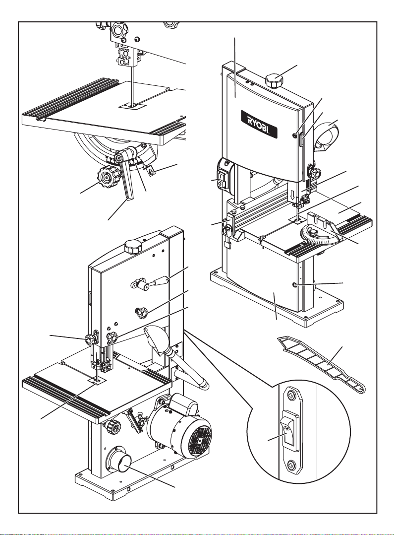
DESCRIPTION
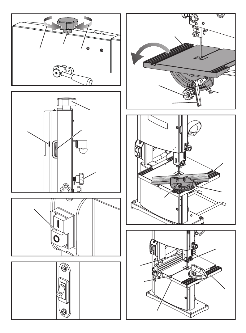
1. Blade tension knob
2. Cover locking screw
3. Tracking view window
4. Work light
5. Blade guard
6. Saw blade
7. Mitre gauge
8. Dust exhaust port
9. Scale indicator
10. Angle adjustment knob
11. Scale
12. Table lock lever
13. Lock knob
14. Blade guide adjustment knob
15. Blade tension lever
16. Throat plate
17. Tracking knob
18. ON/OFF switch
19. Saw table
20. Front-lower panel
21. Front-upper panel
22. Rip fence
23. Work light switch
24. Push stick
25. Phillips screwdriver (not included)
26. Adjustable wrench (not included)
27. Small combination square (not included)
28. Hex key, 3 mm
29. Hex key, 4 mm
30. Hex key, 5 mm
31. Washer
32. Cap nuts
33. Washers
34. Feet
35. Lock bolts
36. Hex nuts
37. Support extension
38. Holes in saw base
39. D-nut
40. Wing screw
41. Saw table bracket
42. Blade guide assembly
43. Adjusting bolt
44. To decrease tension
45. To increase tension
46. Lock knob
47. Mitre gauge slot
48. Phillips screws
49. Upper wheel
50. Lower blade guides
51. Lower wheel
52. Unlock
53. Lock
54. Thrust bearing
55. Thrust bearing screw
56. Blade guide support screw
57. Upper blade guide support
58. Blade guide
59. Blade guide set screw
60. Blade guide screw
61. Lower blade guide support
62. Brush
63. Washer
64. Screw
65. Tire
2
Page 3
21
1
2
3
4
9
18
10
12
14
16
11
22
15
17
13
20
OFF
23
5
6
19
7
2
24
8
Fig. 1
3
Page 4
25 26 27
Fig. 2
32
33
34
38
28
29
30
7
35
37
12
31
32
33
34
39
19
31
40
Fig. 4
19
33
36
Fig. 3 Fig. 5
4
Page 5
31
12
37
35
36
33
13
14
42
Fig. 6
31
12
13
27
10
41
10
Fig. 7
43
9
Fig. 8 Fig. 9
5
12
Page 6
19
44 45
2
18
1
Fig. 10
1
3
17
Fig. 11
10
9
12
46
Fig. 14
47
7
Fig. 15
Fig. 12
Fig. 13
48
5
39
19
40
6
Fig. 16
Page 7
15
13
17
1
49
14
42
Fig. 18
42
6
50
51
Fig. 17
53
52
Fig. 19
7
Page 8

56
61
60
13
54
55
56
55
54
Fig. 21
57
59
58
6
Fig. 20
51
62
63
64
65
Fig. 22
8
Page 9

Important!
It is essential that you read the instructions in this manual before
operating this machine.
Subject to technical modications.
9
Page 10

GENERAL POWER TOOL SAFETY WARNINGS
WARNING
When using electric tools, basic safety precautions
should always be followed to reduce the risk of re,
electric shock and personal injury.
Read all these instructions before attempting to
operate this product and save these instructions.
■ Know your power tool. Read the operator’s manual
carefully. Learn the applications and limitations as well
as the specific potential hazards related to this tool.
■ Guard against electrical shock by preventing body
contact with grounded surfaces. For example: pipes,
radiators, ranges, refrigerator enclosures.
■ Keep guards in place and in good working order.
■ Remove adjusting keys and wrenches. Form habit
of checking to see that keys and adjusting wrenches
are removed from tool before turning it on.
■ Keep work area clean. Do not leave tools or pieces
of wood on the saw while it is in operation.
■ Do not use in dangerous environments. Do not use
power tools near gasoline or other flammable liquids,
in damp or wet locations or expose them to rain. Keep
the work area well lit.
■ Keep children and visitors away. All visitors should
wear safety glasses and be kept a safe distance from
work area.
■ Make workshop childproof with padlocks, master
switches, or by removing starter keys.
■ Don’t force the tool. It will do the job better and safer
at the feed rate for which it was designed.
■ Use the right tool. Do not force the tool or attachment
to do a job for which it was not designed.
■ Dress properly. Do not wear loose clothing, gloves,
neckties, or jewellery. They can get caught and draw
you into moving parts. Rubber gloves and nonskid
footwear are recommended when working outdoors.
Also wear protective hair covering to contain long hair.
■ Always wear safety glasses with side shields.
Everyday eyeglasses have only impact-resistant
lenses; they are not safety glasses.
■ Secure work. Use clamps or a vice to hold work when
practical. It is safer than using your hand and frees
both hands to operate the tool.
■ Don’t overreach. Keep proper footing and balance at
all times.
■ Maintain tools with care. Keep tools sharp and clean
for better and safer performance. Follow instructions
for lubricating and changing accessories.
■ Disconnect tools. When not in use, before servicing,
or when changing attachments, blades, bits, cutters,
etc., all tools should be disconnected from power
source.
■ Avoid accidental starting. Be sure switch is off when
plugging in any tool.
■ Use recommended accessories. Consult the
operator’s manual for recommended accessories. The
use of improper accessories may result in injury.
■ Never stand on tool. Serious injury could occur
if the tool is tipped or if the blade is unintentionally
contacted.
■ Check for damaged parts. Check for alignment of
moving parts, binding of moving parts, breakage of
parts, mounting and any other conditions that may
affect its operation. A guard or other part that is
damaged must be properly repaired or replaced by
an authorised service centre to avoid risk of personal
injury.
■ Use the right direction of feed. Feed work into a
blade or cutter against the direction or rotation of the
blade or cutter only.
■ Never leave tool running unattended. Turn the
power off. Don't leave tool until it comes to a complete
stop.
■ Do not abuse cord. Never carry tool by the cord or
yank it to disconnect from receptacle. Keep cord away
from heat, oil, and sharp edges.
■ Use outdoor extension cords. When tool is used
outdoors, use only extension cords with approved
ground connection that are intended for use outdoors
and so marked.
■ Protect your lungs. Wear a face or dust mask if the
cutting operation is dusty.
■ Protect your hearing. Wear hearing protection during
extended periods of operation.
■ Blade coasts after being turned off.
■ Never use in an explosive atmosphere. Normal
sparking of the motor could ignite fumes.
■ Inspect tool cords periodically. If damaged,
have repaired by a qualified service technician at
an authorised service facility. The conductor with
insulation having an outer surface that is green with
or without yellow stripes is the equipment-grounding
conductor. If repair or replacement of the electric cord
or plug is necessary, do not connect the equipmentgrounding conductor to a live terminal. Repair or
replace a damaged or worn cord immediately. Stay
constantly aware of cord location and keep it well
away from the rotating blade.
■ Inspect extension cords periodically and replace if
damaged.
■ Ground all tools. If tool is equipped with three-prong
plug, it should be plugged into a three-hole electrical
receptacle.
■ Check with a qualified electrician or service
10
Page 11

personnel if the grounding instructions are not
completely understood or if in doubt as to whether the
tool is properly grounded.
■ Use only correct electrical devices: 3-wire extension
cords that have 3-prong grounding plugs and 3-pole
receptacles that accept the tool’s plug.
■ Do not modify the plug provided. If it will not fit the
outlet, have the proper outlet installed by a qualified
electrician.
■ Keep tool dry, clean, and free from oil and grease.
Always use a clean cloth when cleaning. Never use
brake fluids, gasoline, petroleum-based products, or
any solvents to clean tool.
■ Stay alert and exercise control. Watch what you are
doing and use common sense. Do not operate tool
when you are tired. Do not rush.
■ Do not use tool if switch does not turn it on and off.
Have defective switches replaced by an authorised
service centre.
■ Before making a cut, be sure all adjustments are
secure.
■ Be sure blade path is free of nails. Inspect for and
remove all nails from lumber before cutting.
■ Never touch blade or other moving parts during use.
■ Never start a tool when any rotating component is
in contact with the workpiece.
■ Do not operate a tool while under the influence of
drugs, alcohol, or any medication.
■ When servicing use only identical replacement parts.
Use of any other parts may create a hazard or cause
product damage.
■ Use only recommended accessories listed in
this manual or addenda. Use of accessories that
are not listed may cause the risk of personal injury.
Instructions for safe use of accessories are included
with the accessory.
■ Double check all setups. Make sure blade is tight
and not making contact with saw or workpiece before
connecting to power supply.
SPECIAL SAFETY RULES
■ Firmly clamp or bolt the saw to a work bench or leg
stand at approximately hip height.
■ Never operate the saw on the floor.
■ Avoid awkward operations and hand positions
where a sudden slip could cause your hand to move
into the blade. Always make sure you have good
balance.
■ Allow the motor to come up to full speed before
starting a cut to avoid binding or stalling.
■ Do not use tool if switch does not turn it on and off.
Have defective switches replaced by an authorised
service centre.
■ Replacement parts. All repairs, whether electrical or
mechanical, should be made by a qualified service
technician at an authorised service centre.
■ When servicing use only identical replacement parts.
Use of any other parts may create a hazard or cause
product damage.
■ Keep hands away from cutting area. Do not hand
hold pieces so small that your fingers go under the
blade guard. Do not reach underneath work or in
blade cutting path with your hands and fingers for any
reason.
■ Never cut more than one piece at a time or stack
more than one workpiece on the saw table at a time.
■ Do not feed the material too quickly. Do not force
the workpiece against the blade.
■ Use only correct blades. Use the right blade size and
style for the material and the type of cut. Blade teeth
should point down toward the table.
■ Always support large workpieces while cutting to
minimize risk of blade pinching and kickback. Saw
may slip, walk or slide while cutting large or heavy
boards.
■ Do not remove jammed cutoff pieces until blade has
stopped.
■ Never touch blade or other moving parts during use.
■ Before changing the setup and removing covers,
guards or blades, unplug the saw from the power
source.
■ Hold the workpiece firmly against the saw table.
■ To avoid accidental blade contact, minimize blade
breakage, and provide maximum blade support,
always adjust the blade guide assembly to just clear
the workpiece.
■ Keep blades clean, sharp, and with sufficient set.
Sharp blades minimize stalling and kickbacks.
■ Always turn off saw before disconnecting it to avoid
accidental starting when reconnecting to a power
source.
■ Make sure work area has ample lighting to see the
work and that no obstructions will interfere with safe
operation before performing any work using your saw.
■ The blade guides have been preset at the factory.
These settings are functional for some applications.
We recommend that you check and adjust blade
guide settings before first use of your saw. Refer to
Adjusting thrust bearings and blade guide support
procedures explained in the Adjustments section of
this operator’s manual.
■ Do not use tool to cut metal.
■ This tool should have the following markings:
a) wear eye protection.
b) keep fingers away from the blade.
c) do not remove jammed or cutoff pieces until the
11
Page 12

blade has stopped.
d) be sure blade is installed with teeth pointing down.
e) maintain proper adjustment of the blade tension,
blade guides, and thrust bearings.
f) adjust the upper guide to just clear the workpiece.
g) hold the workpiece firmly against the table when
cutting.
■ If the power supply cord is damaged, it must be
replaced only by the manufacturer or by an authorised
service centre to avoid risk.
■ Save these instructions. Refer to them frequently
and use them to instruct other users. If you loan
someone this tool, loan them these instructions also.
ELECTRICAL
EXTENSION CORDS
Use only 3-wire extension cords that have 3-prong
grounding plugs and 3-pole receptacles that accept the
product’s plug. When using a power tool at a considerable
distance from the power source, use an extension cord
heavy enough to carry the current that the product will
draw. An undersized extension cord will cause a drop in
line voltage, resulting in a loss of power and causing the
motor to overheat.
Before using an extension cord, inspect it for loose or
exposed wires and cut or worn insulation.
WARNING
Keep the extension cord clear of the working area.
Position the cord so that it will not get caught on lumber,
tools, or other obstructions while you are working with
a power tool. Failure to do so can result in serious
personal injury.
WARNING
Check extension cords before each use. If damaged
replace immediately. Never use the product with a
damaged cord since touching the damaged area could
cause electrical shock resulting in serious injury.
ELECTRICAL CONNECTION
This product is powered by a precision-built electric motor.
It should be connected to a power supply that is 220-240
V, AC only (normal household current), 50 Hz. Do not
operate this product on direct current (DC). A substantial
voltage drop will cause a loss of power and the motor will
overheat. If the product does not operate when plugged
into an outlet, double check the power supply.
SPEED AND WIRING
The no-load speed of this product is approximately 40m/s.
This speed is not constant and decreases under a load
or with lower voltage. For voltage, the wiring in a shop
is as important as the motor’s horsepower rating. A line
intended only for lights cannot properly carry a power tool
motor. Wire that is heavy enough for a short distance will
be too light for a greater distance. A line that can support
one power tool may not be able to support two or three
products.
GROUNDING INSTRUCTIONS
This product must be grounded. In the event of a
malfunction or breakdown, grounding provides a path
of least resistance for electric current to reduce the
risk of electric shock. This product is equipped with an
electric cord having an equipment-grounding conductor
and a grounding plug. The plug must be plugged into a
matching outlet that is properly installed and grounded in
accordance with all local codes and ordinances.
Do not modify the plug provided. If it will not t the outlet,
have the proper outlet installed by a qualied electrician.
Repair or replace a damaged or worn cord immediately.
SPECIFICATIONS
Product Specifications
Net weight 19.6 kg
Blade Width 3.2 mm to 9.5 mm
Blade Length 1572 mm (62")
Frame to Blade Capacity 230 mm (9")
Cutting Thickness Capacity 80 mm (3-1/8")
Table Size 305 mm x 305 mm
Input 220-240 V, 1.46 Amps,
No Load Speed 40m/s
Dust Port 53 mm (2-1/8")
Work light power 15 W, 230 V
KNOW YOUR BAND SAW
See Figure 1.
The safe use of this product requires an understanding of
the information on the tool and in this operator’s manual
as well as a knowledge of the project you are attempting.
Before use of this product, familiarize yourself with all
operating features and safety rules.
ANGLE ADJUSTMENT KNOB
Tilts the saw table for bevel cutting.
(1/8" to 3/8")
(12" x 12")
50 Hz.
12
Page 13

BLADE GUARD
Protects the operator from coming in contact with the
blade.
BLADE GUIDE ADJUSTMENT KNOB
Use the blade guide adjustment knob to adjust the blade
guide assembly up and down, and to keep the blade
from twisting or breaking. Always lock the blade guide
assembly in place before turning on the band saw.
BLADE GUIDES
Upper and lower blade guides helps keep the blade from
twisting during operation.
DUST EXHAUST PORT
A 53 mm (2-1/8") dust exhaust port makes dustless cutting
possible. Attach a dust bag (not included) or a shop vac to
the dust exhaust port.
COVER LOCKING SCREW
Allows front cover to be opened for making adjustments.
MITRE GAUGE
This gauge aligns the wood for a crosscut. The easy-toread indicator shows the exact angle for a mitre cut at 90°
and 45°.
RAPIDSET™ BLADE TENSION LEVER
Controls blade tension when changing blades and making
adjustments for various sawing applications.
SAW BLADE
Saw comes with a standard 6.35 mm (1/4”) blade.
SAW TABLE WITH THROAT PLATE
Your band saw has a saw table with tilt control. The throat
plate, installed in the saw table at the factory, allows for
blade clearance.
SCALE AND SCALE INDICATOR
The scale and scale indicator show the angle or degree
the saw table is tilted for bevel cutting.
TABLE LOCK LEVER
Loosening the table lock lever allows the saw table to be
tilted at different angles. Tightening the table lock lever
locks the saw table in place.
TRACKING KNOB
Adjusts tracking to keep blade centred on the wheels.
TRACKING VIEW WINDOW
The tracking view window makes tracking adjustments
easier to see.
PUSH STICK
Always use the push stick to feed the workpiece until it is
clear of the table.
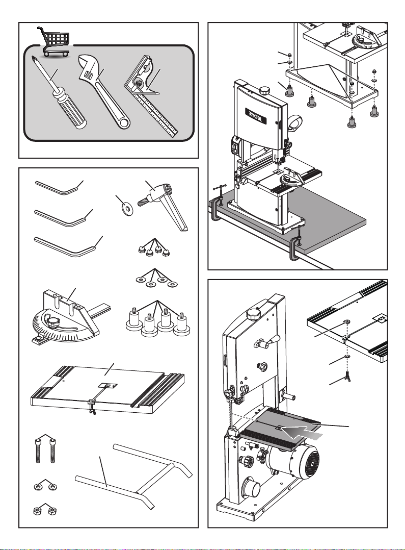
LOOSE PART LIST
Item Description
1 Washers
2 Table lock lever
3 Hex key, 3 mm
4 Hex key, 4 mm
5 Hex key, 5 mm
6 Mitre gauge
7 Acorn nuts
8 Feets
9 Saw table
10 Locking bolts
11 Hex nuts
12 Extension support
ASSEMBLY
UNPACKING
This product requires assembly.
■ Carefully lift the saw from the carton and place on a
level work surface.
WARNING
Do not use this product if any parts on the Loose Part
List are already assembled to your product when you
unpack it. Parts on this list are not assembled to the
product by the manufacturer and require customer
installation. Use of a product that may have been
improperly assembled could result in serious personal
injury.
■ Inspect the tool carefully to make sure no
breakage or damage occurred during shipping.
NOTE: This saw has been shipped with no blade
tension. Do not turn this saw on until blade tension has
been properly set.
■ Do not discard the packing material until you have
carefully inspected and satisfactorily operated the tool.
■ If any parts are damaged or missing, please call your
service centre for assistance.
13
Page 14

WARNING
If any parts are damaged or missing do not operate this
product until the parts are replaced. Use of this product
with damaged or missing parts could result in serious
personal injury.
WARNING
Do not attempt to modify this tool or create accessories
not recommended for use with this tool. Any such
alteration or modication is misuse and could result
in a hazardous condition leading to possible serious
personal injury.
WARNING
Do not connect to power supply until assembly is
complete. Failure to comply could result in accidental
starting and possible serious personal injury.
MOUNTING BAND SAW TO WORKBENCH
If the band saw is to be used in a permanent location, the
band saw must be mounted to a rm supporting surface
such as a workbench. Four bolt holes have been provided
in the saw’s base for this purpose. Bolts (not included)
should be of sufcient length to accommodate the saw
base, lock washers (not included), hex nuts (not included),
and the thickness of the workbench. Tighten all four bolts
securely.
Carefully check the workbench after mounting to make
sure that no movement can occur during use. If any
tipping, sliding, or walking is noted, secure the workbench
to the oor before operating.
■ Place band saw on the workbench. Using the saw
base as a pattern, locate and mark the holes where
the band saw is to be mounted.
■ Drill holes through the workbench.
■ Place band saw on the workbench aligning holes in
the saw base with the holes drilled in the workbench.
■ Insert bolts (not included) and tighten securely
with lock washers and hex nuts (not included).
NOTE: all bolts should be inserted from the top. Install
the lock washers and hex nuts from the underside of
the bench.
CLAMPING BAND SAW TO WORKBENCH
See Figure 4.
If the band saw is to be used as a portable tool, it is
recommended that you fasten it permanently to a mounting
board that can easily be clamped to a workbench or other
supporting surface. The mounting board should be of
sufcient size to avoid tipping of saw while in use. Any
good grade plywood or chipboard with a 19 mm (3/4”)
Thickness is recommended.
If lag bolts are used, make sure they are long enough to
go through holes in the saw base and material the saw is
being mounted to. If machine bolts are being used, make
sure bolts are long enough to go through holes in the saw
base, the material being mounted to, and the lock washers
and hex nuts.
NOTE: it may be necessary to countersink hex nuts and
washers on bottom side of mounting board.
■ Mount saw to board using holes in saw base as a
template for hole pattern. Locate and mark the holes
where the band saw is to be mounted.
■ Follow the last three steps in the section Mounting
Band Saw to Workbench, shown above.
MOUNTING THE SAW TABLE
See Figures 5, 7.
■ Remove the d-nut, washers, and wing screw on the
saw table.
■ Standing at the front of the band saw, slide the saw
table past the blade and through the slot moving from
the right side of the saw table to the left.
■ Holding the saw table with your left hand while pulling
the angle adjustment knob away from the saw frame,
align the teeth on the saw table bracket into the teeth
on the angle adjustment knob. Release the knob.
■ Fit the pins on the frame into the slots of the saw table
bracket.
■ Insert the washer on the threaded end of the table
lock lever. Tighten the saw table to the saw frame by
turning the table lock lever clockwise.
■ Attach the d-nut, washers, and wing screw to the saw
table.
NOTE: the wing screw goes below the saw table.
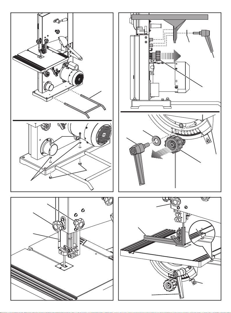
INSTALLING EXTENSION SUPPORT
See Figure 6.
■ Insert the tubes of the extension support into the holes
in the saw base from the rear.
■ Align the holes on the tubes and those on the saw
base.
■ Insert locking bolts and tighten with washers and hex
nuts.
SQUARING THE SAW TABLE TO THE BLADE
See Figures 8 - 9.
■ Turn the lock knob counterclockwise to unlock the
blade guide assembly. Turning the blade guide
adjustment knob clockwise, raise the blade guide
assembly as far as it will go. Turn the lock knob
clockwise to retighten.
■ Place a small combination square on the saw table
beside the blade.
■ Loosen the table lock lever and rotate the angle
adjustment knob to tilt the saw table up or down to
align table 90° to blade (0° position). Retighten the
14
Page 15

table lock lever.
■ Using an adjustable wrench, loosen the jam nut.
■ Turn the adjusting bolt until the bolt just touches the
saw housing.
■ Check squareness of the saw table to the blade. Make
readjustments if necessary.
■ Once squareness is confirmed, retighten the jam nut.
■ Set scale indicator to zero and tighten screw with a
phillips screwdriver.
NOTE: always make a test cut to insure the squareness of
the blade prior to beginning any new project. If not square,
it may be necessary to loosen the screws under the saw
table to make the adjustment (mitre slot must be parallel to
the saw blade). Once square, retighten screws.
ADJUSTING BLADE TENSION
See Figures 10-11.
■ Switch off the saw.
■ Before using the band saw, turn the blade tension knob
on the top of the saw clockwise to engage tension.
■ Note: adjustments of blade tension can be made at
anytime.
■ Pluck the back straight edge of the saw blade like a
guitar string while turning the tension knob.
Sound becomes higher pitched as tension increases.
Never increase blade tension so tight as to completely
compress the spring. When completely compressed, the
spring can no longer act as a shock absorber.
Too much tension may cause the blade to break. Thicker
workpieces require higher tension; maximum tension is
not needed for all cuts. Too little tension may cause the
blade to slip on the wheels.
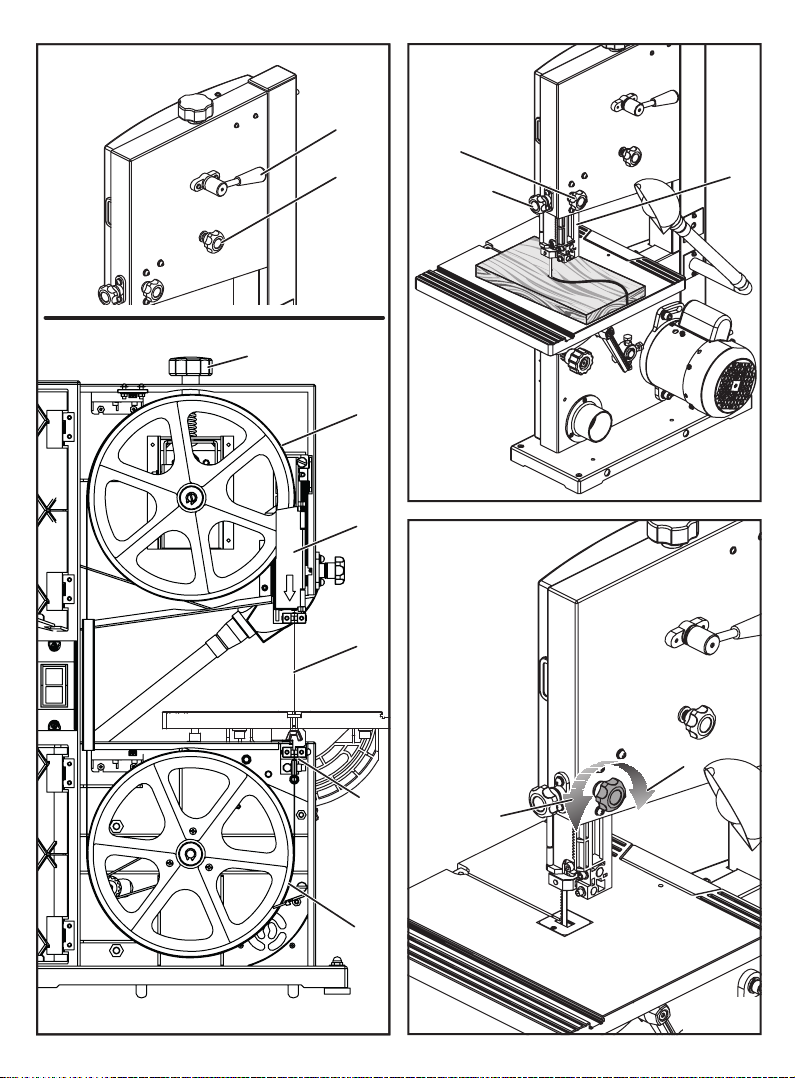
TRACKING THE BLADE
See Figure 11.
Adjust blade tension properly before making tracking
adjustments. Check that blade guides do not interfere
with the blade. Blade gullet (the deepest part of the blade
tooth) should be in the centre of the tire.
To adjust:
Disconnect from power. Open front covers by unscrewing
the cover locking screw. Watch the blade’s position on the
upper tire as, by hand, you slowly turn the upper wheel
clockwise. If the blade moves away from the centre of the
tire, the tracking must be adjusted.
If the blade has moved left or right of centre:
■ Turn the blade tracking knob (clockwise if blade has
moved left; counterclockwise if blade has moved right)
while turning the wheel by hand until the blade moves
back and rides in the centre of the tire.
■ Check the position of the blade on the lower tire. The
blade should be completely on the tire (gullet of the
blade teeth in the centre). If not, adjust the tracking
until the blade is on both tires.
■ Rotate the upper wheel by hand in a clockwise
direction for a few more turns. Make sure the blade
stays in the same location on the tires. Readjust, if
necessary, until blade is tracking properly.
■ Close front covers and tighten cover locking screw.
■ Switch on the saw.
■ Verify saw blade is centred on the tire (through the
tracking view window). If not centred, repeat above
steps.
WARNING
The blade guides have been preset at the factory.
These settings are functional for some applications.
We recommend that you check and adjust blade guide
settings before rst use of your saw. Refer to Adjusting
Blade Guide Support and Thrust Bearings
procedures explained in the "Adjustment" section of this
operator’s manual.
INSTALLING THE RIP FENCE
■ Place the rip fence on the left side of the saw table,
with the lock handle at the front.
■ Push down the lock handle to lock the position of the
rip fence.
■ Turn the lock handle to adjust tightness of the clamps.
OPERATION
WARNING
Do not allow familiarity with the product to make you
careless. Remember that a careless fraction of a
second is sufcient to inict serious injury.
WARNING
Always wear eye protection. Failure to do so could
result in objects being thrown into your eyes, resulting
in possible serious injury.
WARNING
Do not use any attachments or accessories not
recommended by the manufacturer of this product. The
use of attachments or accessories not recommended
can result in serious personal injury.
15
Page 16

WARNING
To avoid blade contact, adjust the blade guide assembly
to just clear the workpiece. Failure to do so could result
in serious personal injury.
WARNING
Never operate saw without the blade guard secured
and the front covers locked. To do so could result in
serious personal injury.
APPLICATIONS
You may use this product for the purposes listed below:
■ Scroll cutting and circle cutting of wood and wood
composition products
■ Various straight line cutting operations in wood and
wood composition products
BASIC OPERATION OF THE BAND SAW
A band saw is basically a “curve cutting” machine that
can also be used for straight-line cutting operations like
cross cutting, mitring, beveling, compound cutting, and
resawing. When using the band saw for straight line
cutting, the user can install a fence using an appropriately
sized piece of wood clamped to the table with “C” clamps.
It is not capable of making inside or non-through cuts.
Before starting a cut, watch the saw run. If you experience
excessive vibration or unusual noise, stop immediately.
Turn the saw off and unplug the saw. Do not restart until
locating and correcting the problem.
CUTTING PROCEDURES
■ Hold the workpiece firmly against the saw table.
■ Use gentle pressure and both hands when feeding the
work into the blade. Do not force the work; allow the
blade to cut.
■ The smallest diameter circle that can be cut is
determined by blade width. A 6.35 mm (1/4”) wide
blade will cut a minimum diameter of 38 mm (1-1/2”); a
3.2 mm (1/8”) wide blade will cut a minimum diameter
of 13 mm (1/2”).
■ Keep your hands away from the blade. Do not hand
hold pieces so small your fingers will go under the
blade guard.
■ Avoid awkward operations and hand positions where
a sudden slip could cause serious injury from contact
with the blade. Never place hands in blade path.
■ Use extra supports (tables, saw horses, blocks, etc.)
when cutting large, small, or awkward workpieces.
■ Never use a person as a substitute for a table
extension or as additional support for a workpiece that
is longer or wider than the basic saw table.
■ When cutting irregularly shaped workpieces, plan your
work so it will not pinch the blade. For example, a piece
of molding must lay flat on the saw table. Workpieces
must not twist, rock, or slip while being cut.
When backing up the workpiece, the blade may bind in
the kerf (cut). This is usually caused by sawdust clogging
the kerf or when the blade comes out of the guides. If this
happens:
■ Switch off the saw. Wait until the saw has come to a
full and complete stop. Unplug the saw from the power
source.
■ Wedge the kerf open with a flat screwdriver or wooden
wedge.
■ Open front cover and turn the upper wheel by hand
while backing up the workpiece.
RELIEF CUTS
Relief cuts are made when an intricate curve (too small
a radius for the blade) is to be cut. Cut through a scrap
section of the workpiece to curve in pattern line then
carefully back the blade out. Several relief cuts should be
made for intricate curves before following the pattern line
as sections are cut off of curve “relieving” blade pressure.
SCROLL CUTTING
For general type scroll cutting, follow the pattern lines by
pushing and turning the workpiece at the same time. Do
not try to turn the workpiece while engaged in the blade
without pushing it – the workpiece could bind or twist the
blade.
REMOVING JAMMED MATERIAL
Never remove jammed cutoff pieces until the blade has
come to a full and complete stop.
■ Switch off the saw. Wait until the saw has come to a
full and complete stop.
■ Unplug the saw from the power source before
removing jammed material.
AVOIDING INJURY
■ Make sure saw is level and does not rock. Saw should
always be on a firm, level surface with plenty of room
for handling and properly supporting the workpiece.
■ Bolt saw to the support surface to prevent slipping,
walking, or sliding during operations like cutting long,
heavy boards.
■ Switch off the saw and unplug cord from the power
source before moving the saw.
■ Do not remove jammed cutoff pieces until blade has
come to a full and complete stop.
■ Choose the right size and style blade for the material
and type of cut you plan to do.
■ Make sure that the blade teeth point down toward the
saw table, that the blade guides, thrust bearings, and
blade tension are properly adjusted, that the blade
guide knob is tight, and that no parts have excessive
16
Page 17

play.
■ To avoid accidental blade contact, minimize blade
breakage, and provide maximum blade support,
always adjust the blade guide assembly to just clear
the workpiece.
■ Use only recommended accessories.
■ With the exception of the workpiece and related
support devices, clear everything off the saw table
before turning the saw on.
■ Properly support round materials such as dowel rods
or tubing because they have a tendency to roll during
a cut causing the blade to “bite”. To avoid this, always
use a “V” block or clamp workpiece to a mitre gauge.
■ Before removing loose pieces from the saw table,
switch off the saw and wait for all moving parts to stop.
SWITCHING ON/OFF THE PRODUCT
See Figure 12.
■ Press I to switch on the product.
■ Press O to switch off the product.
BEFORE LEAVING THE SAW
See Figure 12.
■ Switch off the saw. Wait until the saw has come to a
full and complete stop.
■ Unplug the saw from the power source.
■ Make workshop childproof.
■ Release the tension from the saw blade using the
Rapidset™ blade tension lever to prolong the life of
the blade.
■ Lock the shop.
SWITCHING ON/OFF THE WORK LIGHT
See gure 13.
■ Press to switch on work light.
■ Press OFF to switch off work light.
TILTING THE TABLE
See Figure 14.
■ Loosen the table lock knob slightly.
■ Turn the angle adjustment knob, tilting the saw table
until it reaches the desired angle.
■ Using the scale indicator, check angle markings.
■ Retighten the table lock knob to hold saw table
securely in place.
OPERATION
USING THE MITRE GAUGE
See Figures 15 - 16.
The mitre gauge can be turned 30° to the right or left.
■ Loosen the lock knob on the mitre gauge.
■ With the mitre gauge in the mitre gauge slot, rotate
the gauge until the desired angle is reached on the
index scale.
■ Retighten the lock knob.
USING THE RIP FENCE
The rip fence is used for all ripping operations. Never rip
freehand without the fence in place and securely locked.
■ Position the fence to the desired width of the rip and
lock it in place.
■ Before starting to rip, be sure the rip fence is parallel
to the saw blade. When ripping long boards or large
panels, always use a work support.
■ Hold the piece against the fence and feed it through
the saw blade with a smooth, steady pressure.
ADJUSTMENTS
WARNING
Before performing any adjustment, make sure the tool
is unplugged from the power supply and the switch is in
the off position. Failure to heed this warning could result
in serious personal injury.
WARNING
To avoid personal injury, maintain proper adjustment of
blade tension, blade tracking, blade guides, and thrust
bearings.
INSTALLING AND ADJUSTING THE BLADE
See Figure 17.
■ Loosen and remove the wing screw, washers, and
D-nut from the saw table.
■ Open the front covers by unscrewing the cover locking
screw.
■ Turn the lock knob counterclockwise to unlock the
blade guide assembly. Turning the blade guide
knob (clockwise raises the blade guide assembly;
counterclockwise lowers it), position the blade guide
assembly about halfway between the saw table and
saw housing. Retighten the lock knob.
■ Open the blade guard by pulling the left side of the
guard out and away from the wheel.
■ Release all blade tension from the blade.
■ Carefully remove the old blade.
■ Wearing gloves, carefully uncoil the new blade at arms
length. If the new blade was oiled to prevent rusting,
it may need to be wiped to keep the oil from your
workpiece. Carefully wipe in the same direction the
teeth are pointing so the rag does not catch on the
teeth of the saw blade.
17
Page 18

NOTE: The blade may need to be turned inside out if the
teeth are pointing in the wrong direction. Hold the blade
with both hands and rotate it inward.
■ With the teeth of the blade toward the left of the saw
and facing downward, place the blade through the
lower blade guides and around both wheels.
■ Slowly turn the upper wheel to the right or clockwise by
hand to centre the blade on the rubber tires.
■ Re-engage the RapidSet™ blade tension lever then
adjust the blade tension; check or adjust the blade
tracking.
■ Adjust both upper and lower blade guides and thrust
bearings as explained later in this Operator’s Manual.
■ Reattach the wing screw, washers, and D-nut. Tighten
securely.
■ Close the blade guard and front cover. Tighten the
cover locking screw.
ADJUSTING BLADE GUIDE ASSEMBLY
See Figures 18 - 19.
To prevent the blade from twisting or breaking, the blade
guide assembly should always be set approximately 3.2
mm (1/8”) above the workpiece.
■ Turn the lock knob counterclockwise to unlock the
blade guide assembly.
■ As a guide, use a scrap piece of the same wood you
are about to cut to set the height of the blade guide
assembly. Adjust the blade guide assembly by turning
the blade guide knob.
■ Lock blade guide assembly in place by turning the lock
knob clockwise.
■ Always lock the blade guide assembly in place before
turning on the band saw.
ADJUSTING BLADE GUIDE SUPPORT AND THRUST
BEARINGS
See Figures 20 - 21.
NOTE: Tighten the lock knob and refer to Adjusting
Blade Tension and Tracking the Blade procedures
explained in the ASSEMBLY section of this operator’s
manual prior to making adjustments.
The upper and lower blade thrust bearings support and
bearing guides the saw blade during cutting operations.
The adjustment of the bearings and guides should be
checked whenever a different blade is installed.
To adjust thrust bearings:
The thrust bearings support the back edge of the blade
during cutting. The blade should not contact the thrust
bearings when you stop cutting. It is important that both
upper and lower thrust bearings be adjusted equally.
■ Open the front covers and blade guard.
■ Using a hex key, loosen the upper and lower thrust
bearing screws and push thrust bearings to the back
of the saw.
■ Verify that saw blade is tracking correctly, then slide
the thrust bearing forward until the bearing is within
0.4 mm (1/64”) of the blade. Tighten the thrust bearing
screw securely.
■ Slide lower bearing forward until it has proper
clearance. Tighten the thrust bearing screw securely.
To adjust blade guide support:
■ Loosen the blade guide support and blade guide set
screws using hex keys.
■ Slide the upper blade guide support on the shaft until
the front edge of the guides contact the saw blade
behind the gullet. Tighten the screw securely.
■ Push the right guide to contact the blade and release.
Slowly rotate wheel one full rotation. Tighten blade
guide set screws.
■ Adjust left side guide to allow 0.4 mm (1/64”) clearance
between the blade and guide (about the thickness of a
playing card) by inserting a playing card between left
guide and blade.
■ Apply pressure to left guide pin to hold the playing card
in place. Tighten set screw and remove the playing
card.
■ Rotate, by hand, a full three rotations to make sure
blade will not bind.
■ Close the blade guard and front cover. Lock with
screw.
Repeat this procedure for the lower blade guide support.
ADJUSTING THE RIP FENCE
■ Loosen the lock handle by turning it counterclockwise.
■ Move the rip fence to the desired position.
■ Push down the lock handle to lock the position of the
rip fence.
■ Turn the lock handle to adjust tightness of the clamps.
MAINTENANCE
WARNING
When servicing, use only identical replacement parts.
Use of any other parts can create a hazard or cause
product damage.
WARNING
Always wear eye protection during product operation. If
operation is dusty, also wear a dust mask.
18
Page 19

WARNING
Before performing any maintenance, make sure the tool
is unplugged from the power supply and the switch is in
the off position. Failure to heed this warning could result
in serious personal injury.
GENERAL MAINTENANCE
Avoid using solvents when cleaning plastic parts. Most
plastics are susceptible to damage from various types of
commercial solvents and may be damaged by their use.
Use clean cloths to remove dirt, dust, oil, grease, etc.
adjusted or replaced.
■ Remove the screw and washer then pull the brush off.
■ Place the new brush in the groove.
■ Reinstall using the washer and screw.
ENVIRONMENTAL PROTECTION
Recycle raw materials instead of disposing
of as waste. The machine, accessories
and packaging should be sorted for
environmental-friendly recycling.
WARNING
Do not at any time let brake uids, gasoline, petroleum-
based products, penetrating oils, etc., come in contact
with plastic parts. Chemicals can damage, weaken or
destroy plastic which may result in serious personal
injury.
■ Keep your band saw clean.
■ Remove sawdust from the inside frequently.
■ Do not allow pitch to accumulate on the saw table,
blade guides, or thrust bearings. Clean them with gum
and pitch remover.
■ Apply a thin coat of automobile type wax to the saw
table’s top so the wood slides easily while cutting.
Lubrication
All of the bearings in this tool are lubricated with a sufcient
amount of high grade lubricant for the life of the unit
under normal operating conditions. Therefore, no further
lubrication is required.
TIRES
Cleaning tires:
■ Pitch and sawdust accumulates on tires and needs to
be removed with a fine wire brush or a piece of wood.
Do not use a sharp knife or any kind of solvent.
Replacing tires:
■ Open front cover and remove saw blade. See section
on Installing and Adjusting the Blade.
■ Pry the worn tire away from the wheel carefully.
■ Stretch the new tire around the wheel.
■ Replace the saw blade and close the front cover.
BRUSH
See Figure 22.
There is a brush located inside the saw housing next to the
wheel. It helps protect the tire and wheel by brushing off
saw dust. As the brush becomes worn, it will need to be
SYMBOL
Safety alert
Regulatory Compliance Mark (RCM). Product
meets applicable regulatory requirements.
Please read the instructions carefully before
starting the product.
Wear eye protection.
Wear ear protection.
Wear ear protection, eye protection and a
mask.
DANGER! Sharp blade.
Lock
Unlock
Waste electrical products should not be
disposed of with household waste. Please
recycle where facilities exist. Check with your
Local Authority or retailer for recycling advice.
19
Page 20

TROUBLE SHOOTING
PROBLEM CAUSE SOLUTION
Motor will not run. 1. Problem with ON/OFF switch
Blade does not run in the
approximate centre of the upper
wheel.
Band Saw slows down when 1. Cutting too small a radius.
Blade breaking. 1. Too much blade tension.
Saw is noisy when running. 1. Too much blade tension.
Blade will not cut straight. 1. Blade guides and bearings not
Blade guides will not stay in
position.
Motor runs but blade does not
turn
or power cord.
2. Motor defective.
3. Blade is binding.
1. Not tracking properly. 1. Adjust tracking, See ADJUSTMENTS
2. Dull blade.
2. Kink in blade caused by cutting
too small radius or turning the
material too fast when cutting.
3. Thrust bearings scarred or not
rotating.
2. Blade guides and bearings are
in contact with the blade.
properly adjusted.
2. Worn or defective blade.
1. Blade guide screws have
loosened.
1. Tension not set properly.
2. Drive belt broken.
1. Have worn parts replaced before
using band saw again.
2. Do not attempt any repair. Have
tool repaired by a qualied service
technician.
3. Remove jammed material.
section, “Tracking the Blade”.
2. Have tool repaired by a qualied
service technician.
1. Stop feeding and back up the cutting
material slightly until the band saw
speeds up.
2. Replace blade.
1. Adjust tension. See ADJUSTMENTS
section, Adjusting Blade Tension.
2. Use correct cutting technique. See
section, Operation.
3. Replace the thrust bearings.
1. Adjust tension. See ADJUSTMENTS
section, Adjusting Blade Tension.
2. Adjust upper and lower blade guides
and bearings. See ADJUSTMENTS
sections, Adjusting Thrust Bearings
and Blade Guide Support.
1. Adjust upper and lower blade guides
and bearings. See ADJUSTMENTS
sections, Adjusting Thrust Bearings
and Blade Guide Support.
2. Replace blade.
1. Tighten blade guide screws securely.
1. Use Rapidset Blade Tension Lever to
set tension.
2. Have tool repaired by a qualied
service technician.
20
Page 21

Techtronic Industries (Australia) Pty. Ltd.
Level 1, 660 Doncaster Road
Doncaster, VIC 3108, Australia
Techtronic Industries New Zealand Ltd.
18-26 Amelia Earhart Avenue
Mangere, Auckland 2022, New Zealand
 Loading...