

Page 1
RACO-G
AIR CUTTING OFF GRINDER
OPERATOR'S MANUAL
ORIGINAL INSTRUCTIONS
Page 2

Important!
It is essential that you read the instructions in this manual before
operating this machine.
Subject to technical modifications.
Page 3
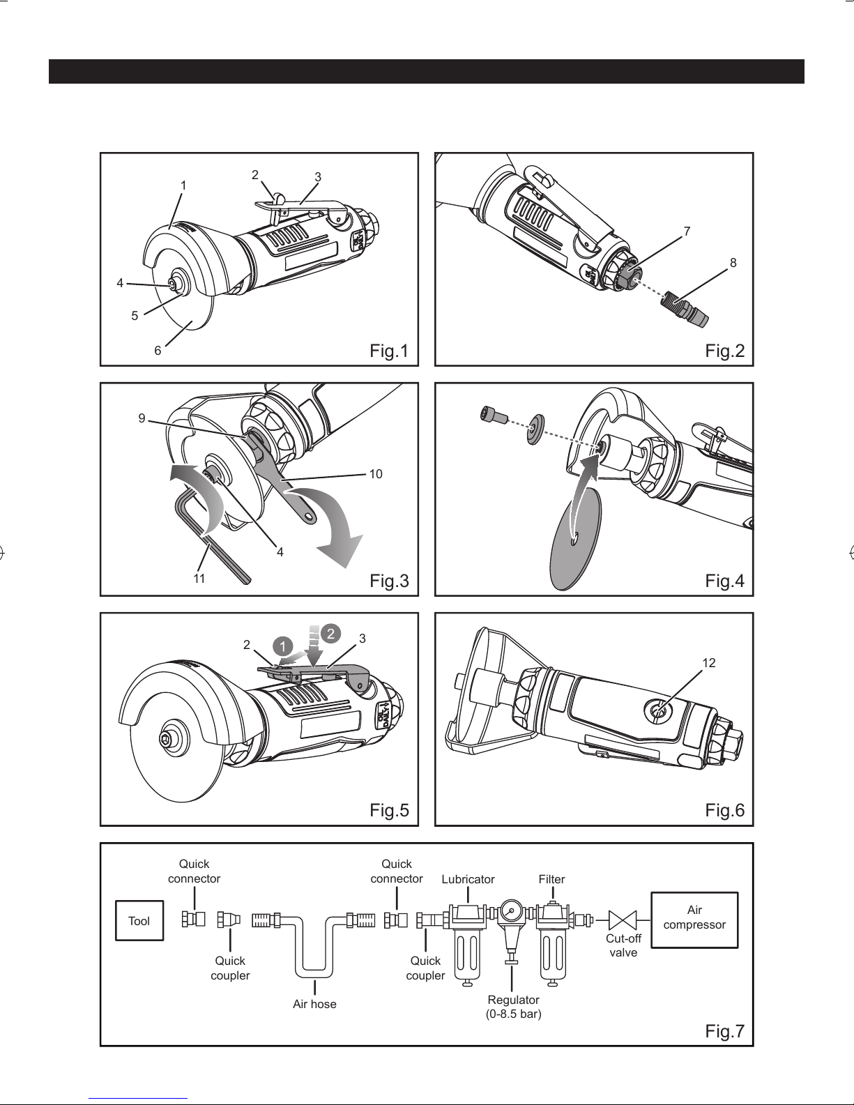
DESCRIPTION
4
1
2
3
7
8
5
6
11
9
4
12
10
3
2
Fig.1 Fig.2
Fig.3 Fig.4
Fig.5 Fig.6
Fig.7
Quick
connector
Quick
connector
Lubricator Filter
Cut-off
valve
Regulator
(0-8.5 bar)
Quick
coupler
Tool
Air
compressor
Quick
coupler
Air hose
1. Guard
2. Trigger lock pin
3. Trigger
4. Lock washer nut
5. Lock washer
6. Cutting off wheel
7. Air inlet
8. Nitto style coupler
9. Collet
10. Wrench
11. Hex key
12. Adjustment knob
Page 4

GENERAL SAFETY RULES
■ For multiple hazards, read and understand the safety
instructions before installing, operating, repairing,
maintaining, changing accessories on, or working
near, the grinder. Failure to do so can result in serious
bodily injury.
■ Only qualified and trained operators should install,
adjust or use the grinder.
■ Do not modify this grinder. Modifications can reduce
the effectiveness of safety measures and increase the
risks to the operator.
■ Do not discard the safety instructions; give them to the
operator.
■ Do not use the grinder if it has been damaged.
■ Tools shall be inspected periodically to verify that the
ratings and markings required by this part of ISO 11148
are legibly marked on the tool. The employer/user
shall contact the manufacturer to obtain replacement
marking labels when necessary.
PROJECTILE HAZARDS
■ Be aware that the failure of the work piece or
accessories, or even of the inserted tool itself, can
generate high-velocity projectiles.
■ Always wear impact-resistant eye protection during
the operation of the grinder. The grade of protection
required should be assessed for each use.
■ Ensure that the work piece is securely fixed.
■ Ensure safe clamping of the abrasive product to the
grinder.
■ Check that maximum operating speed of the abrasive
product, converted to revolutions per minute, is equal
to, or greater than, the rated speed of the spindle.
■ Ensure that the guard is in place, is in good condition
and is correctly mounted; ensure that the guard is
regularly inspected.
■ Check regularly that the speed of the grinder is not
higher than that marked on it. These speed checks
shall be carried out without the abrasive product
mounted and in accordance with the instructions given
by the manufacturer.
■ Check that the flanges, as specified by the
manufacturer, are used and are in good condition, e.g.
free from cracks and burrs, and are plane.
■ Check that the spindle and spindle threads are not
damaged or worn.
■ Ensure that sparks and debris resulting from use do
not create a hazard.
■ Disconnect the grinder from the energy supply before
changing abrasive product and servicing.
ENTANGLEMENT HAZARDS
Choking, scalping and/or lacerations can occur if loose
clothing, personal jewelry, neck wear, hair or gloves are
not kept away from the tool and accessories.
OPERATING HAZARDS
■ Avoid contact with the rotating spindle and
mounted wheel to prevent cutting of hands and
other body parts. Use of the tool can expose the
operator’s hands to hazards, including cuts, abrasions
and heat. Wear suitable gloves to protect hands.
■ Operators and maintenance personnel shall be
physically able to handle the bulk, mass and power
of the tool.
■ Hold the tool correctly; be ready to counteract normal
or sudden movements and have both hands available.
■ Maintain a balanced body position and secure footing.
■ Release the start-and-stop device in the case of an
interruption of the energy supply.
■ Use only lubricants recommended by the manufacturer.
■ Personal protective safety glasses shall be
used; suitable gloves and protective clothing are
recommended.
■ For overhead work, wear a safety helmet.
■ The stopping time, if longer than 5 s, shall be stated,
and it shall be recommended that the grinder be
placed in a stable position.
■ When cutting off, the work piece shall be supported
such that the slot is kept at constant or increasing
width during the complete operation.
■ If the abrasive product becomes jammed in a cut
slot, shut off the grinder and ease the wheel free.
Check that the wheel is still correctly secured and not
damaged before continuing the operation.
■ Grinding wheels and cutting-off wheels shall not be
used for side grinding. (Exception: grinding wheels
designed for side grinding.) Grinders shall not be used
over the maximum peripheral speed of an abrasive
product.
■ The operator shall pay attention that no bystanders
are in the vicinity.
■ Personal protective equipment, such as suitable
gloves, an apron and a helmet, shall be used.
■ Grinding sparks can ignite clothing and cause severe
burns. Ensure sparks do not land on clothing. Wear
fire-retardant clothing and have a bucket of water
nearby.
REPETITIVE MOTIONS HAZARDS
■ When using a grinder to perform work-related
activities, the operator can experience discomfort in
the hands, arms, shoulders, neck or other parts of the
body.
■ When using a grinder, the operator should adopt a
1
Page 5

comfortable posture while maintaining secure footing
and avoiding awkward or off-balanced postures. The
operator should change posture during extended
tasks; this can help avoid discomfort and fatigue.
■ If the operator experiences symptoms, such as
persistent or recurring discomfort, pain, throbbing,
aching, tingling, numbness, burning sensations or
stiffness, these warning signs should not be ignored.
The operator should tell the employer and consult a
qualified health professional.
ACCESSORY HAZARDS
■ Disconnect the grinder from the energy supply before
fitting or changing the inserted tool or accessory.
■ Only use sizes and types of accessories and
consumables that are recommended by the grinder
manufacturer; do not use other types or sizes of
accessories or consumables.
■ Ensure that the dimensions of the abrasive product
are compatible with the grinder and that the abrasive
product fits the spindle.
■ Ensure that the thread type and size of the abrasive
product exactly match the thread type and size of the
spindle.
■ Inspect the abrasive product before use. Do not use
abrasive products which can (possibly) have been
dropped or which are chipped, cracked or otherwise
defective.
■ Ensure that the abrasive product is correctly mounted
and tightened before use and run the grinder at noload speed for at least 1 min in a safe position; stop
immediately if considerable vibration or other defects
are detected and determine the cause of these defects.
■ Prevent the spindle end from touching the bottom of
the hole of cups, cones or plugs with threaded holes,
intended to be mounted on machine spindles, by
checking their dimensions and other relevant data.
■ Where abrasive products are supplied or used with
reducing adaptors or bushings, the user shall ensure
that the adaptor or bushing does not contact the face
of the flange and that the clamping force provides
sufficient rotational driving action to prevent the
abrasive product from slipping.
■ In cases where flanges are supplied for several types
or sizes of abrasive, always fit the correct flange(s) for
the abrasive being used.
■ Avoid direct contact with the inserted tool during and
after use as it can be hot or sharp.
■ Store and handle the abrasive product with care in
accordance with manufacturer’s instructions.
WORKPLACE HAZARDS
■ Slips, trips and falls are major causes of workplace
injury. Be aware of slippery surfaces caused by use of
the tool and also of trip hazards caused by the air line
or hydraulic hose.
■ Proceed with care in unfamiliar surroundings. There
can be hidden hazards, such as electricity or other
utility lines.
■ This grinder is not intended for use in potentially
explosive atmospheres and is not insulated from
coming into contact with electric power.
■ Ensure that there are no electrical cables, gas pipes,
etc., which can cause a hazard if damaged by use of
the tool.
DUST AND FUME HAZARDS
■ Dusts and fumes generated while using grinders can
cause ill health (for example cancer, birth defects,
asthma and/or dermatitis); risk assessment of these
hazards and implementation of appropriate controls
for these hazards are essential.
■ Risk assessment should include dust created by the
use of the tool and the potential for disturbing existing
dust.
■ Operate and maintain the grinder as recommended in
these instructions, to minimize dust or fume emissions.
■ Direct the exhaust so as to minimize disturbance of
dust in a dust-filled environment.
■ Where dust or fumes are created, the priority shall be
to control them at the point of emission.
■ All integral features or accessories for the collection,
extraction or suppression of airborne dust or fumes
should be correctly used and maintained in accordance
with the manufacturer’s instructions.
■ Select, maintain and replace the consumable/inserted
tool as recommended in the instructions, to prevent an
unnecessary increase in dust or fumes.
■ Use respiratory protection in accordance with
the employer’s instructions and as required by
occupational health and safety regulations.
■ Working with certain materials creates emissions
of dust and fumes, causing a potentially explosive
environment.
NOISE HAZARDS
■ Exposure to high noise levels can cause permanent,
disabling hearing loss and other problems, such
as tinnitus (ringing, buzzing, whistling or humming
in the ears). Therefore, a risk assessment and the
implementation of appropriate controls for these
hazards are essential.
■ Appropriate controls to reduce the risk may include
actions, such as damping materials, to prevent
workpieces from “ringing”.
■ Use hearing protection in accordance with employer’s
instructions and as required by occupational health
and safety regulations.
■ Operate and maintain the grinder as recommended in
the instructions handbook to prevent an unnecessary
increase in noise.
2
Page 6
■ If the grinder has a silencer, always ensure that it is in
place and in good working order whenever the grinder
is being operated.
■ Select, maintain and replace the consumable/inserted
tool as recommended in the instructions handbook to
prevent an unnecessary increase in noise.
VIBRATION HAZARDS
The information for use shall draw attention to vibration
hazards that have not been eliminated by design and
construction and remain as a residual vibration risk. It shall
enable employers to identify the circumstances in which
the operator is likely to be at risk from vibration exposure.
If the vibration emission value obtained using ISO 289271 for angle and vertical grinders, ISO 28927-4 for straight
grinders or ISO 20643 does not adequately represent the
vibration emission in the intended uses (and foreseeable
misuses) of the machine, additional information and/or
warnings shall be supplied to enable the risks arising from
vibration to be assessed and managed.
■ Exposure to vibration can cause disabling damage to
the nerves and blood supply of the hands and arms.
■ Wear warm clothing whenever working in cold
conditions and keep your hands warm and dry.
■ If you experience numbness, tingling, pain or whitening
of the skin in your fingers or hands, stop using the
grinder, tell your employer and consult a physician.
■ Operate and maintain the grinder as recommended in
the instructions handbook to prevent an unnecessary
increase in vibration levels.
■ Do not allow the inserted tool to chatter on the work
piece as this is likely to cause a substantial increase
in vibration.
■ Select, maintain and replace the consumable/inserted
tool as recommended in the instructions handbook to
prevent an unnecessary increase in vibration levels.
■ Support the mass of the tool in a stand, tensioner or
balancer, if possible.
■ Hold the tool with a light but safe grip, taking account
of the required hand reaction forces because the risk
arising from vibration is generally greater where the
grip force is higher.
■ Use blotters where they are provided with the bonded
abrasive product.
ADDITIONAL SAFETY INSTRUCTIONS FOR
PNEUMATIC POWER TOOLS
■ Air under pressure can cause severe injury.
■ Always shut off air supply, drain hose of air pressure
and disconnect tool from air supply whenever not in
use, before changing accessories or where making
repairs.
■ Never direct air at yourself or anyone else.
■ Whipping hoses can cause severe injury. Always
check for damaged or loose hoses and fittings.
■ Whenever universal twist couplings (claw couplings)
are used, lock-pins shall be installed and whipcheck
safety cables shall be used to safeguard against
possible hose-to-tool and hose-to-hose connection
failure.
■ Do not exceed the maximum air pressure stated on
the tool.
■ Never carry an air tool by the hose.
■ The spare parts should be not changed by the user.
■ Regularly check the spindle and wheel fixation for
wear.
SYMBOLS
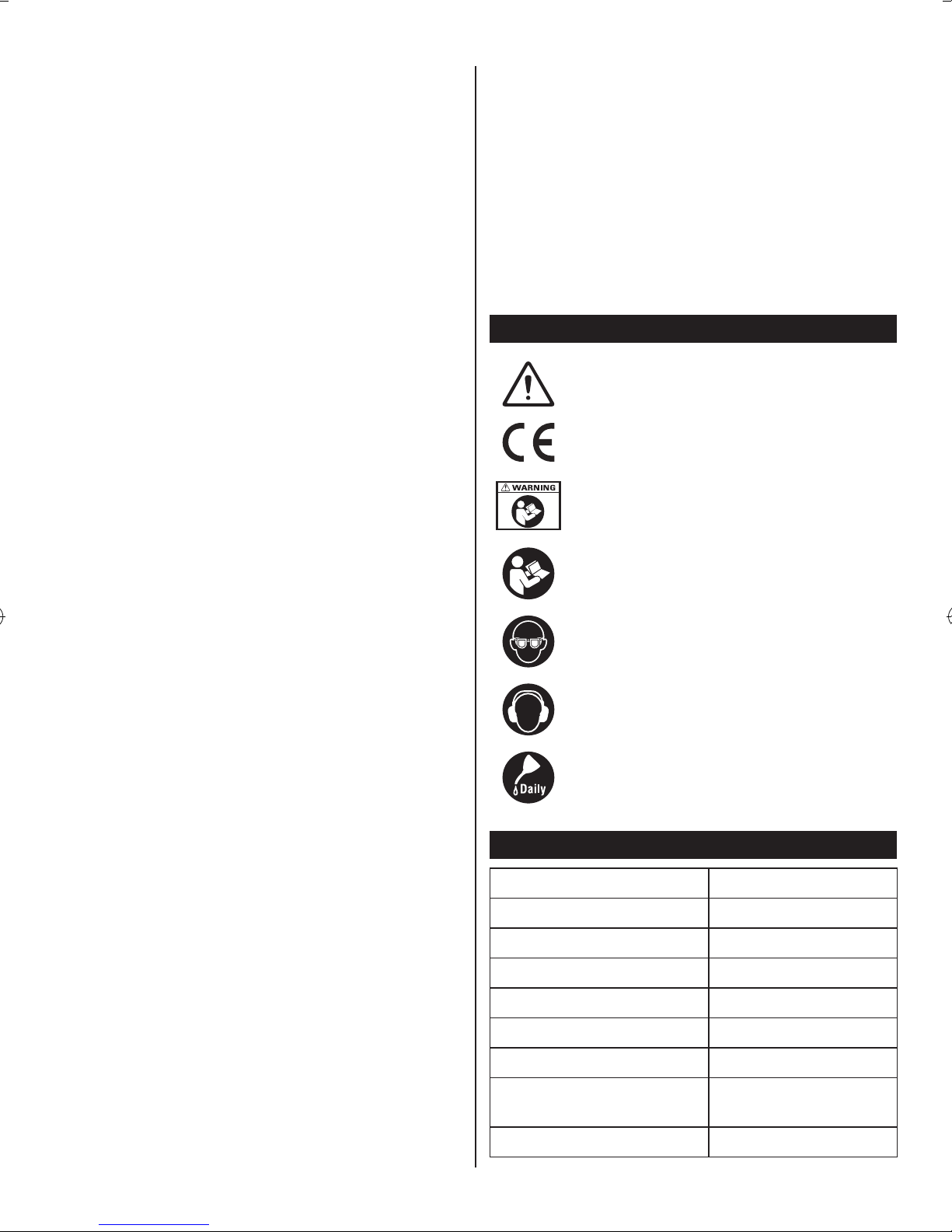
Safety alert
CE conformity
Please read and understand all instructions
before operating the product, follow all
warnings and safety instructions.
Please read the instructions carefully before
starting the product.
Wear eye protection.
Wear ear protection.
Lubricate with air tool oil daily.
SPECIFICATIONS
Capacity 76 mm (3”)
No-load speed 20,000/min
Air consumption 114 L (4 cfm)
Maximum working pressure 6.3 bar (90 psi)
Air inlet size 6.35 mm (1/4”)
Air hose ID 9.52 mm (3/8")
Weight 0.7 kg
A weighted sound pressure
level
Sound power level 90.4dB(A), k=3dB
79.4dB(A), k=3dB
3
Page 7

Vibration value 1.67 m/s
Uncertainty 0.26 m/s
2
2
Noise emission values are in accordance with
EN ISO 4871 and EN ISO 15744.
Vibration emission values are in accordance with
EN12096 and EN28662-1.
APPLICATION
The product is ideal for cutting-off operation. The durable
and lightweight composite housing design also helps
reduce vibration. It has a lever lock throttle for safety. Any
other use is forbidden.
The product can cut aluminum, plastic, ber-glass and
steel. A chrome-plated safety guard and a safety latch
protect the user against injury. A safety lock mechanism
prevents accidental start-ups.
RESIDUAL RISKS
Even if you are operating this product in accordance
with all the safety requirements, potential risks of injury
and damage remain. The following dangers can arise in
connection with the structure and design of this product:
1. Health defects resulting from vibration and noise
emission if the product is being used over long periods
of time or not adequately managed and properly
maintained.
2. Injuries and damage to property due to broken cutting
attachments or the sudden impact of hidden objects
during use.
3. Danger of injury and property damage caused by
ying objects.
AIR SUPPLY AND OPERATION
■ Ensure air valve (or trigger) is in the “off” position
before connecting to the air supply.
■ Connect the product to the air hose.
■ Press the trigger to operate the product.
■ The air regulator controls the amount of air flow
entering the rotor. Turn the air regular adjustment
knob to decrease/increase the speed of the product.
■ Do not allow the product to free run for an extended
period of time as this will shorten its life.
■ There is a risk of excessive vibration levels due to
improper mounting or damage of insert tool.
■ There is a risk of running on of the inserted tool after
the start and stop device has been released.
■ Only permitted insert tools of the correct diameter are
used.
■ Release the start and stop device in the case of an
interruption of the air supply.
■ Disconnect the product from the air supply before
changing accessories or making adjustments.
■ Required air pressure of 6.3 bar (90 psi), and an air
flow according to specifications.
■ Attach the cutting off wheel, lock washer and lock
washer nut to the collet.
■ Tighten the lock washer nut to secure the cutting off
wheel by the provided hex key and wrench.
■ Before operation, ensure the inserted tool is fixed in
the product.
WARNING
Ensure the air supply is clean and does not exceed
6.3 bar (90 psi) while operating the product. Too high an
air pressure and unclean air will shorten the product's
life due to excessive wear, and may be dangerous
causing damage and/or personal injury.
LUBRICATION
An automatic in-line lter-regulator-lubricator is
recommended (Fig. 7) as it increases product life and keeps
the product in sustained operation. The in-line lubricator
should be regularly checked and lled with air tool oil.
Proper adjustment of the in-line lubricator is performed by
placing a sheet of paper next to the exhaust ports and
holding the throttle open for approximately 30 seconds.
The lubricator is properly set when a light stain of oil
collects on the paper. Excessive amounts of oil should be
avoided.
If it becomes necessary to store the product for an extended
period of time (overnight, weekend, etc.), it should receive
a generous amount of lubrication at that time. The product
should be run for approximately 30 seconds to ensure oil
has been evenly distributed throughout the product. The
product should be stored in a clean and dry environment.
● It is most important that the product be properly
lubricated by keeping the air line lubricator filled
and correctly adjusted. Without proper lubrication
the product will not work properly and parts will
wear prematurely.
● Use correct lubricant in the air line lubricator. The
lubricator should be of low air flow or changing air
flow type, and should be kept filled to the correct
level. Use only recommended lubricants, specially
made for pneumatic applications. Substitutes
may harm the rubber compounds in the product's
O-rings and other rubber parts.
4
Page 8

IMPORTANT!
See Figure 7.
If a lter/regulator/lubricator is not installed on the air
system, air operated tools should be lubricated at least
once a day or after 2 hours of work with 2 - 6 drops
of oil, depending on the work environment, directly
through the male tting in the tool housing.
Disconnect tool from the air supply before attempting
repair or adjustment. When replacing O-rings or cylinder,
lubricate with air tool oil before assembly.
PROBLEM: Tool runs at normal speed but fails under
load.
POSSIBLE CAUSES
■ Motor parts are worn.
■ Cam clutch is worn or sticking due to lack of lubricant.
LOADING AND OPERATION
WARNING
Drain the air tank daily. Water in the air line will damage
the tool.
■ Clean the air inlet filter weekly.
■ Line pressure should be increased to compensate for
unusually long air hoses (over 8 metres). The minimum
hose diameter should be 6.35 mm (1/4”) I.D. and the
fittings must have the same inside dimensions.
■ Keep hose away from heat, oil and sharp edges. Check
hose for wear, and make sure that all connections are
secure.
■ Use the tool only for its intended purpose.
MAINTENANCE
■ Keep the product safe by regular maintenance.
■ Always keep your air tool clean and lubricated. Daily
lubrication is essential to avoid internal corrosion and
possible failure.
■ Maintenance shall be performed weekly.
■ Drain the air tank daily. Water in the air line will
damage the product.
■ If the product cannot be used anymore, make sure to
dispose of it so as not to impose hazards on people
and the environment.
■ Air tool white oil is recommended for lubrication.
■ Only lubricants recommended by the manufacturer
should be used.
REMEDIES
■ Lubricate clutch housing.
■ Check for excess clutch oil. Clutch cases need only
be half full. Overfilling can cause drag on high speed
clutch parts, i.e. a typical oiled/lubricated tool requires
14.20 ml (1/2 ounce) of oil.
Grease lubrication
NOTE: Heat usually indicates insufficient grease in
chamber. Severe operating conditions may require
more frequent lubrication.
PROBLEM: Tool runs slowly. Air ows slightly from
exhaust.
POSSIBLE CAUSES
■ Motor parts are jammed with dirt particles.
■ Air regulator is in closed position.
■ Air flow is blocked by dirt.
REMEDIES
■ Check air inlet filter for blockage.
■ Pour air tool lubricating oil into air inlet as per
instructions.
■ Operate tool in short bursts quickly reversing rotation
back and forth where applicable.
■ Repeat above as needed.
PROBLEM: Tool will not run. Air flows freely from
exhaust.
POSSIBLE CAUSE
One or more motor vanes are stuck due to material
build up.
TROUBLESHOOTING
WARNING
If any of the following symptoms appears during
operation, stop using the tool immediately, or serious
personal injury could result. Only qualied persons or
an authorised service centre can perform repairs or
replacement of the tool.
REMEDIES
■ Pour air tool lubricating oil into air inlet.
■ Operate tool in short bursts of forward and/or reverse
rotation where applicable.
■ Tap motor housing gently with a plastic mallet.
■ Disconnect the air supply. Free the motor by rotating
drive shank manually where applicable.
■ If the product remains jammed, return to the service
centre.
5
Page 9

PROBLEM: Tool will not shut off.
POSSIBLE CAUSE
■ ‘O’ rings throttle valve is dislodged from seat inlet
valve.
REMEDY
■ Replace the ‘O’ ring.
NOTE: Repairs should be carried out by a qualied
person.
6
Page 10
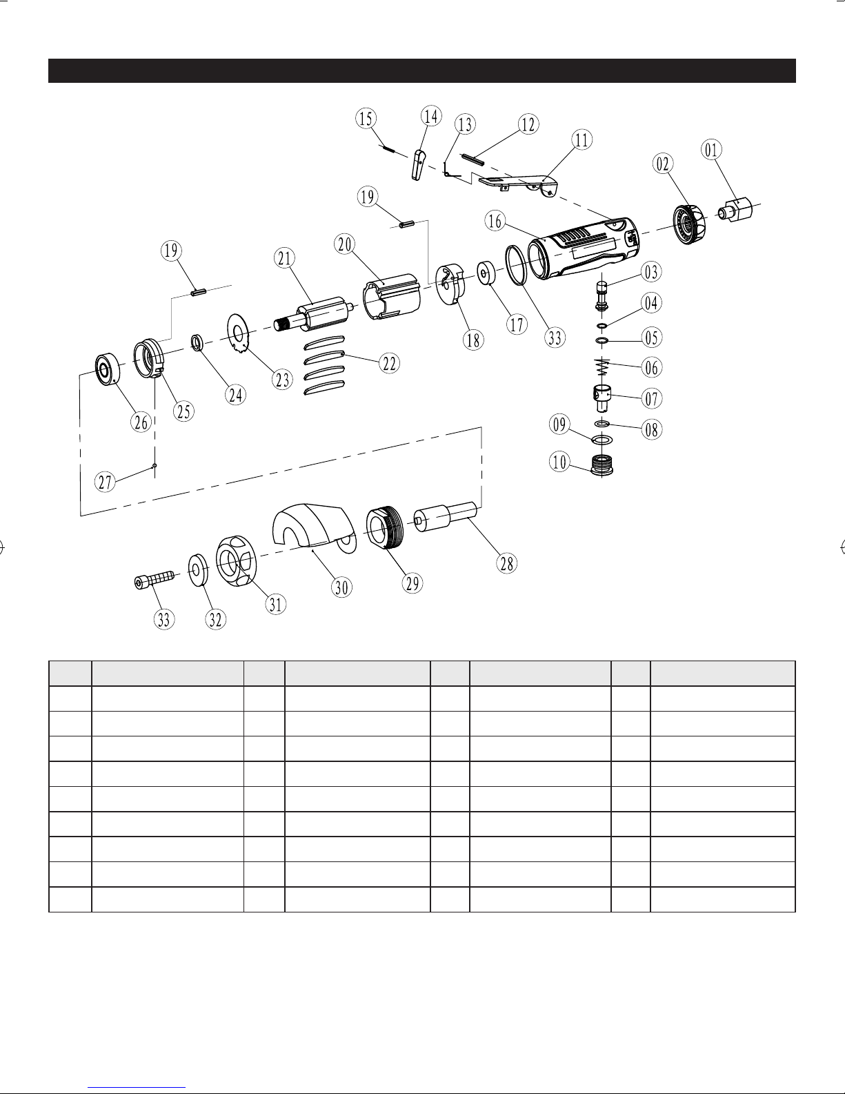
PARTS LIST
No. Description No. Description No. Description No. Description
01 Air inlet valve 10 Screw cap 19 Pin 2 x 6 28 Support seat
02 Mufe cover 11 Trigger 20 Cylinder 29 Lock ring
03 Pin 12 Pin 21 Rotor 30 Cover
04 O-ring 4.8 x 1.6 13 Spring 22 Rotor blade 31 Front cover
05 O-ring 5.6 x 2 14 Trigger lock pin 23 Washer 32 Washer
06 Spring 15 Pin 2 x 18 24 Bushing 33 Bolt
07 Air regulator 16 Housing 25 Front plate
08 O-ring 7 x 2 17 Bearing 26 Bearing
09 O-ring 12 x 3 18 Bearing 27 Steel ball Dw=2
7
Page 11

Techtronic Industries (Australia) Pty. Ltd.
Level 1, 660 Doncaster Road
Doncaster, VIC 3108, Australia
Techtronic Industries New Zealand Ltd.
18-26 Amelia Earhart Avenue
Mangere, Auckland 2022, New Zealand
 Loading...