

Page 1
RyoB
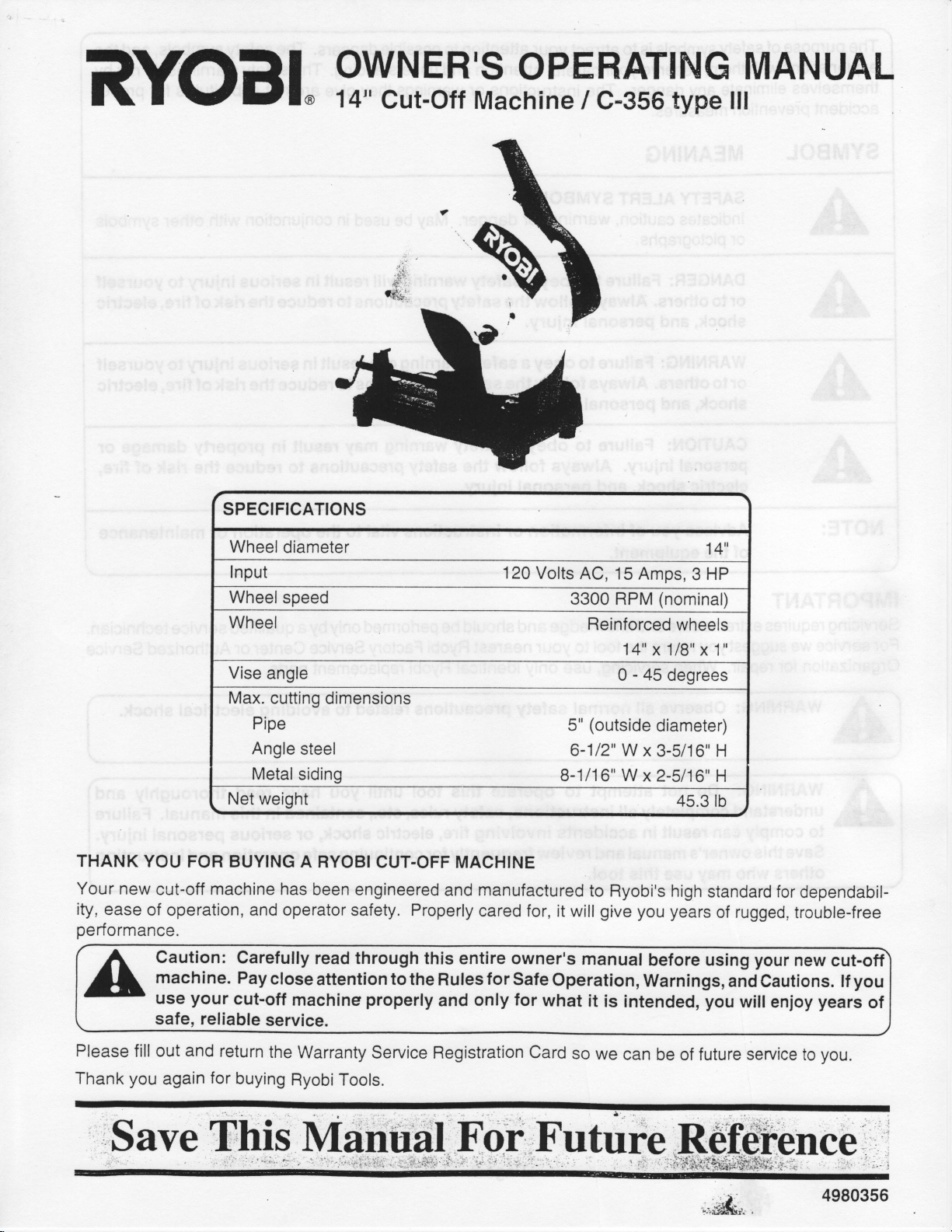
SPECIFICATIONS
g[],F"il.".fl
l.
r"t
F
$l
A N
i]19,,
Ir
uA
L
THANK
Your new
ity, ease
performance.
YOU
FOR
cut-off
of
operation, and operator safety. Properly
Caution:
machine.
your
use
safe,
Wheel
I nput
Wheel
Wheel
Vise
Max.
Net weight
BUYING
machine has
cut-off
reliable
diameter
speed
angle
cutting
Pipe
Angle
Metal
Carefully
Pay
close
service.
dimensions
steel
siding
A RYOBI
been engineered
read
attention
machine
CUT-OFF MACHINE
through
to
the
properly
120
Volts
3300
5"
6-1
B-1l1
manufactured
and
cared for, it
this entire owner's
for
only
Safe
for
Rules
and
will
Operation,
what
AC,
15
Amps,
(nominal)
RPM
Reinforced
14"
0 -
(outside
12" W
W
6"
to Ryobi's high
give
manual
it
is
intended,
wheels
x 1/8"
45
degrees
diameter)
x
3-5/1
x
2-511
45.3 rb
you years
before using
Warnings,
14"
HP
3
x 1"
H
6"
H
6"
standard for
of rugged,
your
and Cautions. lf
you
will
enjoy
dependabil-
trouble-free
new
cut-off
you
years
of
Please
Thank
fill out
you
'Save
and
again
return
for
buying
the
Warranty
RyobiTools.
Service Registration
Card
so
we
can be
of future
service
you.
to
4980356
Page 2
purpose
The
explanations
themselves
accident
of
with
eliminate
prevention
safety
symbols is to
them,
any
measures.
your
attention to
deserve
your
attract
careful attention
danger. The instructions
possible
and
understanding.
dangers.
or warnings they
The
safety symbols,
The safety warnings do not
give
are
not
substitutes for
and the
by
proper
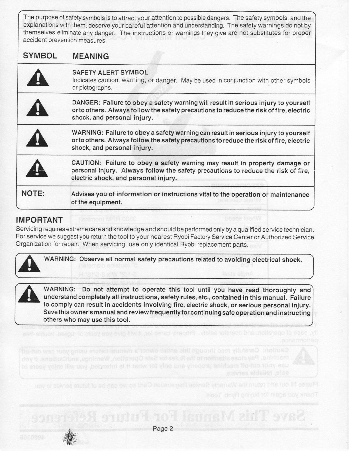
SYMBOL
NOTE:
IMPORTANT
Servicing requires
For service
we
Organization
extreme
suggest
for repair.
MEANING
SAFETY
Indicates
pictographs.
or
DANGER:
ALERT
caution,
Failure to obey
ortoothers. Alwaysfollowthesafetyprecautionstoreducetheriskof
shock, and
WARNING: Failure
to
or
others. Always follow the
shock, and
CAUTION:
pei'sona!
electric
Advises
injury. Always folfow
shock,
you
of the equipment.
care and knowledge
you
return
When
servicing,
SYMBOL
warning,
personal
injury.
to obey a safety warning
personal
Failure to
and
injury.
obey a
personal
of information
and should be
the tool to
your
only identical
use
or danger.
a safety
warning
safety
safety
the safety
injury.
instructions
or
nearest
Ryobi Factory
May
be used
will
can
precautions
warning
precautions
vitalto
performed
conjunction with
in
result
in
serious injury
result in
to reduce
may
result
to
the
operation
only
by a
serious
Service Center
Ryobi replacement
parts.
other
yourself
to
fire,electric
injury to
yourself
the risk of f ire, electric
property
in
reduee
the
damage
risk
or maintenance
qualified
seruice technician.
Authorized
or
symbols
or
fii"e,
of
Seruice
WARNING:
WARNING:
understand
to
comply can result in
Save
this
others
Observe all normal
Do not
completely
owner's manualand reviewfrequentlyforcontinuing
who
may
use
attempt
instructions,
all
accidents
this tool.
safety
to
precautions
operate this
involving
related
tool
safety rules,
fire,
electric
to
avoiding
you
until
etc., contained
shock,
have
in this
or serious
safe
operation
electrlcal shock.
read thoroughly and
manual. Failure
personal
injury.
and instructing
Page
2
Page 3

RULES
FOR
SAFE
OPERATION
READ
ALL
KNOW
operation
Safe
affixed
machine.
to the
SAFETY
KEEP
1.
REMOVE
2.
adjusting
g.
KEEP
DO NOT
4.
flammable
KEEP
S.
work area.
MAKE
6.
DO NOT
7.
8.
USE
WEAR
9.
could
ALWAYS
10.
NOT safety
PROTECT
11.
PROTECT YOUR
12.
SECURE
13.
frees both
and
NOT OVERREACH.
DO
14.
MAINTATNTHETOOLWITHCARE.
15.
Follow
INSTRUCTIONS
YOUR
Keep
WARNING:
and
precautions
WenntXC:
reduce
to
these
POWER
this
of
Learn
tool.
manual
this
adjusted
the
basic
power
Donotconnectyourcut-off
tool
its applications
readily
the machine
operating
and
When
Safety
using
risk of fire,
PRECAUTIONS
PLACE
GUARDS
ADJUSTTNG
wrenches
THE
USE
CHTLDREN
THE
FORCE
RIGHT
THE
PROPER
get
in moving
WEAR
THE
instructions
lN
KEYS
are removed
WORK
liquids,
WORKSHOP
glasses.
YOUR
AREA CLEAN.
DANGEROUS
lN
in
damp
AWAY
TOOL.
THE
TOOL.
APPAREL.
par1s.
SAFETY
LUNGS.
HEARING.
WORK.
hands
Use clamps
to operate
for
changing
TOOL
requires
available
electric tools,
electric
Precautions
in
and
AND
wet locations,
or
FROM
CHILD-PROOF
lt
Do not
Do
Non-slip
GLASSES.
Wear
Wear
the
proper
Keep
accessories.
labels
owner's
you
that
and limitations
for future reference.
as described
instructions
shock,
include
good
working
WRENCHES.
from the
ENVIRONMENTS.
POWER
will
force
not
footwear
a face or dust
or
tool before
Cluttered
or
TOOLS.
with
job
the
do
the tool
wear loose
is recommended.
Everyday
earmuffs
vise
a
to hold
tool'
footing and
Keepsawtoolssharpandcleanforthebestandsafestperformance.
and understand
read
well
as
machinetoapowersourceuntilyouhaveassembled
in this
in the
basic
and
the
work
expose
padlocks
better
or attachment
clothing,
or
manual
safety
personal
following:
order.
in the
Get
turning
areas
Do not
them
visitors should
All
and
eyeglasses
if
mask
plugs
during
work when
balance
the
as
manual and
precautions
habit of checking
it
and
to
master switches
and
safer at
to do a
neckties,
have only
the cutting
periods
practical.
at all times.
this
potential hazards
have read
printed
and
should
injury.
on.
work benches
use
rain. Keep the
Wear
Use common
power
the rate
rinQs,
operation
tools
kept at a safe
be
job
for which
bracelets.
protective
impact-resistant
extended
of
lt is safer than
manual and
peculiar
and understood
tool.
the
on
always
sense.
to see
invite accidents.
work
or by
for which
is dusty.
that
gasoline
near
area
distance
removing
it was
was
it
other
or
covering
lenses;they
use.
using
all
cut-off
a
to
all
be followed
Some
hex keys and
weil
starter
designed.
not
designed.
jewelry
over
your
of
or other
lighted.
from the
keys.
that
hair.
long
are
hands
Page 3
Page 4
16. DISCONNECT
abrasive
17.
REDUCE
before
1
I'
USE ONLY
for
19.
NEVER
is
unintentionally
20'
PERIODICALLY
binding
affect
the tool
its
intended function.
21.
NEVER
it
comes
22.
DO NOT
heat,
23.
KEEP
reach
when
24.
KEEP Tootcleaning.
25.
STAY ALERT.
wheel.
THE
RISK
plugging
THE
recommended
STAND
of moving parts,
operation.
is
used
again,
LEAVE
to
a complete stop
ABUSE THE
oil.
and sharp edges.
HANDS
AWAY FROM
underneath
wheel is
moving.
uHY,
Never
Never
medication.
26. DO
27. ALWAYS
28.
29'
NOT
USE TOOL lF THE
replaced
at a Ryobi Authorized
TURN
ALL
REPAIRS, WHETHER
Service
SAVE THESE
instruct
Center.
INSTRUCTIONS
others who may
POWER
in
the
MANUFACTURER'S
accessories.
ON
TOOLS
UNINTENTIONAL STARTING.
OF
BEFORE
tool.
RECOMMENDED ACCESSORIES.
THE
Using
TOOL.
improper accessories
Serious
contacted.
other
or
WORN
OR DAMAGED
parts,
of
part
that is
that the repaired
UNATTENDED.
CHECK FOR
breakage
guard
A
make sure
THE TOOL RUNNING
and is disconnected
CORD.
work
around
cLtsAN,
use
brake fluids,
operate
Never
THE
AND FREE
yank
CUTTING
or
over
gasoline,
power
a
the
tool
SWITCH DOES NOT
Service Center.
SWITCH
OFF before
disconnecting it
ELECTRICAL
Use only Ryobi
replacement
FOR FUTURE
use this
tool. lf
you
SERVICING
or
Make
injury
could
occur
PARTS.
loose
mounting
brackets, and any
damaged should
replaced
or
Turn
power
from
the
cord to disconnect
AREA.
wheel while it
FRoM
Keep
hands
is rotating.
otl AND
GREASE.
petroleum-based
when
tired
or while
TURN
lT
to avoid
MECHANICAL,
OR
parts.
REFERENCE.
loan
someone
this tool, loan
before
changing
sure the
accessories
switch
Consult
may
increase the
if
the tool
Check
is tipped
risk
for
alignment of
other conditions
properly
be
part
is operating
the
off
repaired
power.
properly
Do not leave
source.
from the
away from
products,
under the
AND
ON
receptacle.
the
abrasive wheels.
Do not
attempt to remove
Atways
use
or any solvents
influence
OFF. Have
accidentalstarting.
should
Refer
be made
to them
frequently
them these
such
in
is
the
OFF
this
Owner's
of injury.
or if the
abrasive wheel
moving
that
replaced.
or
performing
and
the
tool
Keep
the
cord from
material
a ctean cloth when
to clean tool.
of drugs,
defective
at a Ryobi
alcohol,
switches
Authorized
and use them to
instructions,
the
as
position
Manual
parts,
might
Before
until
Do not
or
also.
Page
4
Page 5
CUT-OFF
MAKE
1.
MACHINE
SURE
instructions
cause
CHECK
Z.
g.
USE
with
ALWAYS
4.
impact
BEFORE
5.
IMPORTANT
6.
obtained
cracks.
WHEEL
ONLY
ANSI
can break
by
SAFETY
THE
CUT-OFF
before
CUT-OFF
7.1. Always
B
EASE
CUTTING,
writing to:
connecting
FOR FISSURES
WHEEL
ABRASTVE
THE
wheel.
the
press
INFORMATION
WHEEL
the
toolto a
AND
RATED FOR
wheels in
store
WHEEL
trigger switch
the
THE
ON
GRINDING
30200
Cleveland.
WHEEL INSTITUTE
Detroit Road
OH
lS
SECURELY
power
supply,
CRACKS, and
RPM
3300
a dry
place
with little
AGAINST THE
allow the cut-off
and
CUT.OFF
OF
USE
44145-1967
MOUNTED as
not tighten wheel
Do
for normal
test
GREATER
OR
temperature
WORK
PIECE
wheel
WHEELS
described in
excessively, since
prior
operation
manufactured in
and
to use.
variation.
when starling to cut.
reach f ull
to
AND ANSI
speed before
B 7.1 CAN
the operating
this can
compliance
A harsh
cutting.
bE
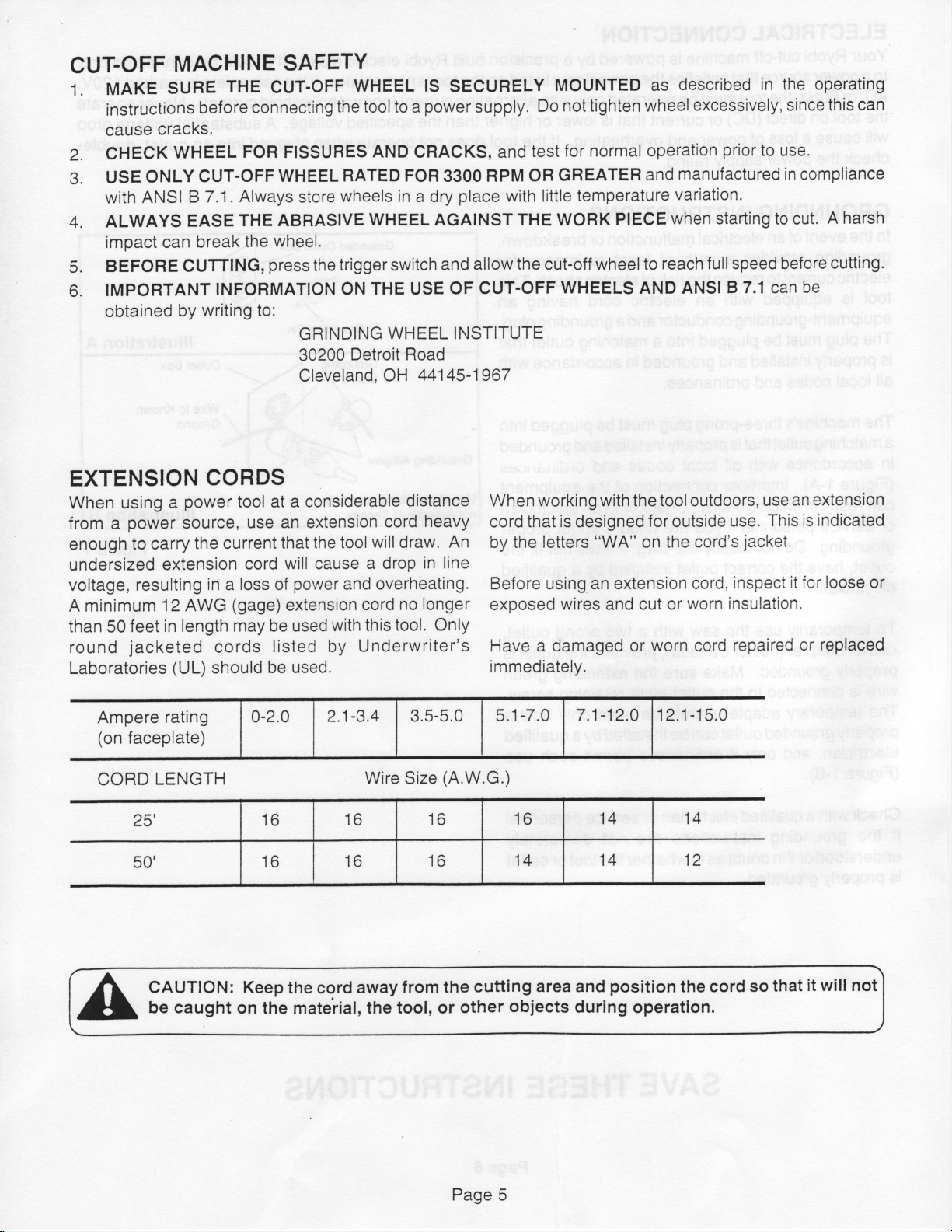
EXTENSION
When using
from a
enough
undersized
voltage, resulting
A minimum
than 50
round
Laboratories
power
to carry
feet
jacketed
Ampere
(on
faceplate)
CORD
LENGTH
CORDS
power
a
source,
the current
extension
in a loss
12 AWG
in length may be used
cords
(UL)
should
rating
2'',
50'
tool at a considerable
use an extension
that the
tool
cord will cause
of
(gage)
extension
power
and overheating.
with
listed by
Underwriter's
distance
cord heavy
will
draw.
a drop
cord no
tool.
this
be used.
-3,4
0-2.0
16
16
2,1
Wire Size
16
16
An
in line
longer
Only
3.5-5.0
(A.W.G.)
16
16
an extension
When
working with the tool outdoors,
cordthatisdesignedforoutsideuse.
by the
Before
exposed wires and cut
Have a damaged or
letters "VVA" on the cord's
an extension cord,
using
worn insulation,
or
worn
cord
use
Thisisindicated
jacket.
inspect
repaired
it for loose or
or
immediately.
5.1
16
14
-7
.0
.1
7
-12.0
14 14
14 12
-15.0
12.1
replaced
CAUTION: Keep
caught
be
on
the mateiial,
the cord
from the
away
the tool, or
cutt
other
Page
ing
area and
obiects
5
position
during
the cord
operation.
so
that
it will not
Page 6

ELECTRICAL
Your
Ryobi
cut-off
toapowersourcethatsatisfiesthepowerinputlistedonthetool'snameplates.
AC,
or 60H2,
the tool
will
check
on direct (DC)
cause
the
a loss
power
the
tool
CONNECTION
machine
must
or
power
of
supply
powered
is
operated only
be
current
that is
and overheating.
rating.
precision
by a
with
lower
lf
built
alternating
higher
or
than
the tool does
Ryobi electric
currerit
(normal
the specified
not
operate
when
lt
motor.
should
be
lfthenameplateismarked
household
voltage.
plugged
current).
A
substantial
into
an
connected
only
1ZOV,
Never
ou1et,
operate
voltage
drop
double-
GROUNDING
In
the
event
of
grounding
electric
tool
is
equipment-grounding
plug
The
properly
is
all
local
The
machine's
a matching
in
acccrdance
(Figure
can
result
or service
grounding.
outlet,
electrician.
To
temporarily
use
an
properfy
wire
is
The
temporary
properly
electrician,
(Figure
provides
current
equipped
must
installed
codes
outletthat
1-A).
in
electric
personnel
Do
have
the
adapter (not
grounded.
connected
grounded
and
1-B).
INSTRUCTIONS
an
electrical
a
to
reduce
with
conductor
plugged
be
and
and
ordinances.
three-prong
properly
is
'with
ali local
lmproper
shock.
you
if
not
modify
correct
use the
adapter
onfy
saw
for
Canada),
Make
to the
outlet
if
ordinances
malf
unction
path
the risk
an
grounded
connection
the
outlet
sure
ouilet-plate
should
can
reast
of
of
electric
electric cord
and
into
matching
a
in
plug
must
installed
codes
of the
Check
are
with
be installed
with
unsure
plug;
installed
a two-prong
provided
the
extending green
be
used
permit
or
breakdown.
resistance
shock.
having
grounding
a
ouilet
accordance
plugged
be
grounded
and
aiid
oi'"iirtar
equipment
an
electrician
about
if
it
will
by
retaining
by
proper
not
qualified
a
ouilet.
the
outlet
screw.
only
until
qualified
a
such
fit
for
This
an
plug.
that
with
intc
rudc
the
is
a
use
Grounding
grounding
Use of
not
available
Grounding
Means
Adapter
adapter
in
Canada.
Groundins
Pin
t4
,/ 'Y-
is
lllustration
Outlet Box
Wire
to
Known
round
G
lllustration
A
B
Figure
1
Check
if
understood
is
with
grounding
the
properly
grounded.
a
or
qualified
if in
electrician
instructions
doubt
or
service
are Frct
as
to
whether
SAVE
completely
the tool
TH
ESE
personnel
or
outlet
I NSTRUCTIONS
Page
6
Page 7

UNPACKING
Caref
1 .
Do
2.
have
List.
lf all
3.
assembly.
4.
lf
obtain
Push
5.
the
Examine
6.
occurred
must
tool.
lly remove all
u
discard
not
identified
parts
you
are
it before
the
handle.
be
the
the
all
have
missing
attempting
handle
all
during
replaced
down and remove
parts
to
shipping.
Trigger
parts
packing
parls
been
part,
a
make sure
before attempting
Lock-On
the shipping
f rom
materials
the
using
included,
contact
to
your
operate
the chain
no breakage has
Any damaged
Machine
Button
Loose Parts
proceed
the
to use
carton.
you
until
dealer
tool.
from
part
the
Handle
to
to
Loose Parts
Cut-off
Wrench
NOTE: Cut-off
WARNING:
locked-down
the
used
chain
storing
warning
InJU
machine
is
the
can
ry.
List
Wheel is
On/Off
feature; see
Trigger
Never
tool. Failure
result in
Owner's
Warranty
operate
position.
only
for
Operating
Registration
factory
Switch
Figure
5
transporting
serious
installed.
(with
for detail)
the
transport
The
heed
to
personal
Manual
Lock-Out
tool
this
Card
in
or
Carrying
External
Power
Transport Chain
Adjustable Depth Stop
Adjustable
Vise
Front
Handle
Brush
Clamp
Caps
Stationary
Vise
Wrench
Shaft
14'
Metal
$r
Quick
Machine
Base
Lever
Lcck
Abrasive
Cutting
Lock-Release
Vise Screw
Wheel,
Shaft
Vise
Crank
Handle
Vise
Page
Fig
7
ure
2
Page 8

ASSEMBLY
Your
Ryobi
cut-off
machine
comes
fulfy
assembled.
WARNING:
power
cornplete.
in
accidentaf
serious
REMOVAL
AND
CUT.OFF
WHEEL
1.
Be
source.
2.
Raise
the
head
wneet
Push
3.
the
locking
while
4.
supplied
bolt
hex
abrasive
REMOVAL
sure the
the
tool to its fulf
lower
wheel
bolt
which
arDor
in
the
wheel
by rotating
head
until
the
wheel in
holding
17
bolt, wosher,
wheel.
Do
source
Failureto
injury.
connect
not
until
comply
starting
INSTALLATION
WHEEL
tool is
(Ftgure
shaft lock
mm wrench
disconnected
position
open
guard
secures
the
it
upward,
the
abrasive wheel
3).
(Figure
lever
the
shaft
place.
shaft lock lever
counterclockwise.
lock
loosen
and
outside flange,
machine
assembly
could
possible
and
OF
from the
and
exposing
lever
place,
in
the
4)
and
engages,
use
the
hex
Remove
to
is
resuft
power
rotate
hex
to
the
rotate
the
head
the
and
Abrasive
Outer
Flange
Washer
Hex
Head
Bolt
Wheel
o
h
Lower
Guard
Wheel
(raised)
Figure
3
NOTE:
The
inside flange
spring
wheel
components;
for
clip
arbor.
wheel
and
changes.
is
held
inner
Do
not
removal
place
in
washer
remove
is
not required
onto
these
by
the
a
Fig
ure
4
Page
B
Page 9

WHEEL
Be sure
1.
Inspect
2.
are
Remove any
3.
INSTALLATION
the tool
the
found or the speed
is
replacement
debris from
inner washer and against
Clean and align the outside
4.
the
abrasive
lnsert the hex head bolt
5.
wheel.
snug. Then depress the
to securely
tighten
disconnected
wheel
rating
the
from
for
defects such
is not
inside
the inside
flange to
the threaded
into
lock lever
shaft
the hex head
bolt to
power
the
greater
flange
than
and inner washer. Position the
flange.
the wheel
end of the
prevent
to
hold
the abrasive wheel
source.
as cracks.
rpm, discard
3300
arbor,
then slide
wheel
the
shaft
chipping,
and
the
correct
wheel
new
it
onto the
arbor
and
f rom
rotating, use the supplied
firmly
arbor
place.
in
it in
rotate
speed
and
abrasive
until
a clockwise
rating. lf
select
another.
wheel
it rests
1
flush against
direction
7 mm wrench
defects
over the
until
WARNING: Do
to crack, resulting
Return the wheel
6.
WARNING
the new wheel does
lowered. Failure to heed this WARNING
TRIGGER
prevent
To
padlock
a
Figure
When
inoperable.
5. Use
the
LOCK
unauthorized use of the
through
a
lock is
Store
guard
: Be
SWITCH
hole in
the
padlock
with a 1
installed
padlock
the
not
overtighten
premature
in
to its lowest
to check the
sure
not cut into
the
switch as
3/64"
locked,
and
in
key
the hex head
position.
position
the work surface
miter
saw, install
shown
shank
another
diameter.
the
switch
location.
failure
in
is
bolt. Overtightening
possibie
and
of the
mach i ne
serious
arm
beneath
can result
in
serious
can cause the
personal
adjustable
the
base when
personal
new wheel
injury.
depth stop
the saw
arm is fully
injury.
to ensure
Page
Figure
9
5
Page 10

ADJUSTIVI
ADJ
USTAB
The
adjustable
your
cut-off
cutting
allow
machine.
angles
greater
cutting
ENTS
LE
STATIONARY
stationary
This
from
0
to
widths.
vise
vise
45
and
located
is
be
can
moved
VISE
at the rear of
rotated
to
rearward
attain
to
WARNING:
from
adjustments
maintenance.
can
CUTTING
To
adjust
1
.
Locate
fence
2.
Using the
bolts
Rotate
3.
is
aligned with the indicator
base.
NOTE:
4.
Check
wheel
device.
5.
Using
two hex
base.
ANGLE
the angle
the
(Figure
the
Angle
vise
the
using
the
head
power
result
Always
Failure
in
serious
unplug
source
performing
or
to heed
personal
ADJUSTM
of cut:
two hex
6).
supplied 17
vise
indicators
base in
angle
protractor,
a
supplied wrench,
bolts
head
bolts behind
mm
wrench,
fence
until
the
groove
are
5 degree increments.
the vise
of
holding
fence
bevel
securely
the vise
the machine
before
this
injury.
ENT
loosen
desired
stamped
square, or
angle
in the machine
the
to
tighten the
to
the machine
making
routine
warning
the vise
both
of cut
into
the
abrasive
similar
Fonruard
Distance
Position,
to Front
Rear
Distance
Vise
Position,
to Front
-1
: 7
Vise:
Adjustable
Stationary
Figure
14"
B-1 12"
6
MOVING
To
increase
1
.
Locate
fence
2.
Locate
directly
3. Using
hex
machine
THE
the
the
(Figure
the
behind
the
head
STATIONARY
width
of
cut
of
two hex head
6).
threaded
supplied
bolts
base.
hole
vise
the
securing
base.
rnm wrench,
17
the
VISE
your
cut-off
bolts behind
the
in
vise
machine:
machine
r€move
to
the
the
vise
base
both
cut-off
Page
Reposition
4.
the
base
NOT
Align
5.
threaded
hex head
Check
6.
tighten
wrench.
1
0
the
most
rearward
and install
TIGHTEN.
the
remaining
hole
bolt.
or
adjust
both
hex head
curved
a hex
in
slot
threaded
head
vise
bolt hole
the machine
the
cutting
bolts
of the vise
hole in
bolt in
angle
the machine
this hole.
with
base
and
and
the
with
Figure
with
base
the
middle
install
securely
supplied
7
Do
a
Page 11

QUICK
cut-off
Your
release
featu
without
vise
you
re
repetitive
close the
and
vise
the
VISE
with
LOCK-RELEASE
is
machine
system
able
are
turning
equipped
as standard equipment.
to
open
of
quick
a
vise
crank
lock-
With
this
quickly
handle.
USING
THE
QUICK
VISE
loosen:
To
1 .
Slightly
crank
Lift up
2.
pull
To tighten:
Push the
1 .
against
Push
2.
(Figure
Rotate
3.
vise
release
handle
the
back
the
down
B)
the crank
against
ADJUSTABLE
As
shown
threaded
raising
wrench
travels
in Figure
into the
lowering
and
you
when
can
the
tension on
counterclockwise
quick
lock-release
on crank
crank
handle
work
on
to engage
work
the
POSITIVE
9,
base of
the depth
control
machine
LOCK.RELEASE
vise by
the
112 to
(Figure
lever
handle
fonrvard
piece.
quick
the
its threads
handle
Piece.
to slide
clockwise
open
to
slide
lock-release
with vise
to
DEPTH STOP
the adjustable
machine
the
stop
how far the
handle
depth
the
at
with
bolt
abrasive
is depressed.
and
8)
vise.
the
vise
the
lever
screw.
stop
rear.
mm
a12
wheel
the
the
By
rotating
1 turn.
tighten
is
Closed
Figure
B
particularly
feature
This
.
TRANSPORT
transport chain
The
machine
and
for carrying
attached
transport
loop
and
machine
the
is
increase
to
wheel
to
tire
or
to
useful after
wheel.
wears,
"cinch-up"
i.rarrspori
during
limittravel
CHAIN
behind
arm,
the
cut-off
to the machine
or store
one
the
of
the
using
useful:
wheel travel
machine's
the
moving
when
chain
storage,
the abrasive
of
installation
is attached to
the
machine
arm
cut-off machine,
chain's
the
links
carrying handle
of a
motor,
is
a
over
the abrasive
as
handle
the
wheel,
the
(Figure
metal
especially
new abrasive
machine base
is
and
lower the
hook.
hook.
the
(Figure
only
9).
against
machine
used
Also
To
handle
Move
2).
Figure
9
Page
1
1
Page 12

OPERATING
POWER
Before
power
listed
cause a
Common
overheating
multiple tools operating
SUPPLY
operating
supply and
on the
nameplate.
loss
of
causes
are insufficient
your,cut-off
make
sure
A
substantial
power
and machine
power
of
from
SWITCH
To
start the
located
To
stop
For continuous operation,
trigger switch and,
depress
tne trigger switch on
To
discontinue continuous
trigger lock-on
trigger switch and
disengage
tool.
completely
in the rnachine
the
the trigger
release
tool,
feature, completely depress
the trigger
handle
while holding it in
lock-on
the
then
lock-on feature.
depress
trigger switch
the
button located
tool
operation
release it.
machine,
meets
it
loss
extension
the
same
(Figure
completely depress
place
handle
check
requirements
the
voltage
overheating.
and
cord size and
power
the
trigger
10).
completely.
(tool
to
(Figure 10).
when using
This action
your
drop
machine
source.
switch
running),
left of
the
the
onlott
will
the
the
will
Figure
10
CUTTING
WARNING: Do
or rnasonry
cut magnesium
this tool. Failure
warning
inju
1.
Secure the tool in
2.
Firmly
3.
Start
before
4.
Slowly
a steady and
5.
When the cut is
open
secure the material
WARNING:
of clamping to be secured
hold
the machine
contacting
push
position.
coufd
ry.
material
by fully depressing
down
even
complete,
not
attempt
with this machine.
or magnesium
to
result in
place
prevent
to
to be
to cut
comply
serious
machine
using
cut
Large, circular, or
place
in
securely.
Failure to
the trigger
wheel to
on
pressure
material.
machine arm
the
to obtain
release
the
wood
Never
alloy with
with
this
personal
movement
machine's
the
tipping
or
vise
during
(Figure
1 1).
irregularly shaped material may
for
adequately
comply
handle
a
uniform
trigger
switch
could
switch
the
until
cut.
and
Never
cutting. Use
result
and allow
cut-off
the
wheel
force
allow the
in serious
cut-otf wheel
contacts
wheel into the material.
the
wheel to
Figure
the
cutting
procedure.
require additional means
"C" clamps and blocks
personal
injury.
to come up to full speed
the material
stop before raising
being
it to
cut.
the
1 1
to
Use
full
,
-l
n
DANGER:
this warning
Donottouchthecutmaterialuntil itcoolsoryouwillbeburned! Failuretoheed
will result
in
serious
personal
Page
injury.
12
Page 13

MAINTENANCE
the tool clean.
Keep
metal
Make
check
Apply dry
extend
L u b
particles
sure
screws
machine
i
ri
cat
Tr:"::l'"w
o
front
o
slide
WARNING:
machine from the
off
before
adiustments.
from
Always disconnect the
servicing
Remove
working
WARNING:
ventilation
not use
tool
the
and
lubricant
when
solvents
operates
for
bolts
monthly
service
life
s h art
vise clamp
vise
of
way
unit
the
accumulated
parts.
Provide
using
clean
to
properly.
tightness.
the
to
(Figure
rotation
shaft
power
or
source
making
dust
adequate
solvents.
plastic
points
12).
parts.
Periodically
listed to
cut-
and
Do
Figure
12
Remove
the
"standard
brush,
It is
the
Authorized Service
!ubr!cat!on.
the brush
carbon
recommended
tool to
brushes.
(Figure
Line"
replace them.
Ryobi
a
WARNING:
reliability, all
of
externally
performed
be
Authorized
Ryobi
replacement
Center
regular
at
caps
When the brushes
13),
?s
that at
Factory Service
least
for a thorough
To
repairs
accessible
at a
Service
intervals
indicated
once
Center
ensure
(with
brushes)
Ryobi
Center.
parts.
to check
to
worn
are
the
on
year
a
cleaning
safety and
the exception
Factory
Use
the
carbon
you
take
Ryobi
or
and
should
or
only
Standard
Line
4'
A
I
I
I
i
Figure
13
Page
1
3
Page 14

O
SERVICE
Now
your
pertinent
O
The model number
O
WHEN
you
that
nearest
facts when
MODEL
HOWTO
ORDERING REPAIR PARTS,
.
MODEL NUMBER
C-356 type lll
.
NAME
14"
purchased
have
Ryobi
of
OF ITEM
Cut-Off Machine
your
tool,
Authorized
you
Service Center or Ryobi Factory
call or
visit.
NO.
your
tool will
ORDER
should a need
be found
on a
ever exist for repair
plate
REPAIR
ALWAYS
.
PART DESCRIPTION
GIVE THE FOLLOWING
Service Center.
attached
to the motor
parts
or service,
Be sure to
housing.
PARTS
INFORMATION:
simply
contact
provide
all
pafts
All
5201
P.O. Box 1207
lisied may
RYOBI AMERICA
Pearman
be ordered from
Dairy
Road Anderson
Phone
1-800-525-2579
any
CORPORATION
SC
29025-8950
Anderson
SC
29622-1207
RyobiAuthorized
Service
Centeror
Cambridge,
Ryobi Factory
RYOBI CANADA,
P.O. Box
Phone
Service
INC.
910
Ontario
1-800-265-6778
N1R
GKz
Center.
 Loading...