

Page 1
CAUTION: Carefully read through this entire owner's manual before using your
plunge router.
SAVE THIS MANUAL FOR FUTURE REFERENCE.
Your new plunge router has been engineered and manufactured to Ryobi's high standard for dependability,
ease of operation and operator safety. Properly cared for, it will give you years of rugged, trouble free
performance.
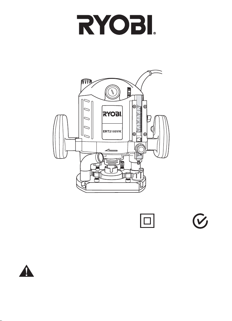
THANK YOU FOR BUYING A RYOBI PLUNGE ROUTER
OWNER’S OPERATING MANUAL
PLUNGE ROUTER
MODEL ERT2100VK
Pay close attention to the Rules for Safe Operation, Warnings, and Cautions.
If you use your plunge router properly and only for what it is intended, you will enjoy years of safe, reliable
service.
Thank You again for buying Ryobi tools.
SPECIFICATIONS :
Input ......................................... 2100 W
No Load Speed ........................ 8000-23000 min
-1
Collet Capacity.......................... 6.35 mm (1/4")
12.7 mm (1/2”)
Plunge Capacity ....................... 60 mm
Net Weight ................................
7.5 kg
N197
DOUBLE
INSULATED
Page 2
The purpose of safety rules is to attract your attention to possible
dangers. The safety symbols and the explanations with them,
require your careful attention and understanding. The safety
warnings do not by themselves elimin ate any danger. The
instruction or warnings they give are not substitutes for proper
accident prevention measures.
1. K
NOW YOUR POWER TOOL. Read owners manual carefully.
Learn its applications and limitations as well as the specic
potential hazards related to this tool.
2. G
UARD AGAINST ELECTRICAL SHOCK BY PREVENTING
BODY CONTACT WITH GROUND ED SURFACES. For
example, pipes, radiators, ranges, refrigerator enclosures.
3. KEEP
WORK AREA CLEAN. Cluttered areas and benches
invite accidents.
4. A
VOID DANGEROUS ENVIRONMENT. Don't use power tools
in damp or wet locations or expose to rain. Keep work area
well lit.
5. K
EEP CHILDREN AND VISITORS AWAY. Visitors should
wear safety glasses and be kept a safe distance from work
area. Do not let visitors contact tool or extension cord.
6. S
TORE IDLE TOOLS. When not in use, tools should be
stored in a dry and high or locked-up place, out of reach of
children.
7. DON'T
FORCE TOOL. It will do the job better and safer at
the rate at which it was designed.
8. USE
RIGHT TOOL. Don't force small tool or attachment to
do the job of a heavy duty tool. Don't use tool for purpose not
intended.
9. DRESS PROPERLY. Do not wear loose cloth ing or
jewellery. They can be caught in moving parts. Rubber
gloves and non-skid footwear are recommended when
working outdoors. Also wear protective hair covering to
contain long hair.
10. A
LWAYS WE AR S AF ETY GL ASS ES . Ev er yday
eyeglasses have only impact resistant lenses, they are
not safety glasses.
11. PR
OTECT YOUR LUNGS. Wear a dust mask if operation
is dusty.
12. P
ROTECT YOUR HEARING. Wear hearing protection
during extended periods of operation.
13. DO
N'T OVERREACH. Keep proper footing and balance at
all times. Do not use tool on a ladder or unstable support.
Secure tools when working at elevated levels.
14. M
AINTAIN TOOLS WITH CARE. Keep tools sharp and
clean for better and safer performance. Follow instructions
for lubricating and changing accessories.
15. REMO
VE ADJUSTING KEYS AND WRENCHES. Form a
habit of checking to see that keys and adjusting wrenches
are removed from tool before turning it on.
16. N
EVER USE IN AN EXPLOSIVE ATMOSPHERE. Normal
sparking of the motor could ignite fumes.
17. KEEP
HANDLES DRY, CLEAN AND FREE FROM OIL
AND GREASE. Always use a clean cloth when cleaning.
Never use brake uids, gasoline, petroleum based products,
or any strong solvents to clean your tool.
18. ST
AY ALERT AND EXERCISE CONTROL. Watch what
you are doing and use common sense. Do not operate tool
when you are tired. Do not rush operation of tool.
19. C
HECK DAMAGED PARTS. Before further use of the
tool, a guard or any other part that is damaged should be
carefully checked to determine that it will operate properly
and perform its intended function. Check for alignment
of moving parts, binding of moving parts, breakage of
parts, mounting and any other conditions that may affect
its operation. A guard or any other part that is damaged
should be properly repaired or replaced by an authorised
service centre.
20. DO
NOT USE TOOL IF SWITCH DOES NOT TURN IT ON
AND OFF. Have defective switches replaced by authorised
service centre.
21. D
O N OT O PE RATE TH IS TOO L WHILE UN DER
THE INFLUENCE OF DRUGS , ALCO HOL OR ANY
MEDICATION.
22. T
HE APP LIANC E IS NOT IN TENDE D FO R US E
BY YO UN G OR I NFI RM PERS ON S WI TH OUT
SU PERVIS IO N. YOUNG CH ILDRE N SHOUL D BE
SUPERVISED TO ENSURE THAT THEY DO NOT PLAY
WITH THE APPLIANCE.
RULES FOR SAFE OPERATION
SAVE THESE INSTRUCTIONS
FOR FUTURE REFERENCE
Due to continued product
renement policy, product features
and specications can and will
change without notice. Check
current features and specications
with your retailer.
SAFETY ALERT SYMBOL. Indicates caution or
warning. May be used in conjunction with other
symbols or pictures.
WARNING: Failure to obey a safety warning can
result in serious injury to yourself or to others.
Always follow the safety precautions to reduce the
risk of re, electric shock and personal injury.
WARNING: Do not attempt to operate this tool
until you have read thoroughly and understood
completely, safety rules, etc. contained in this
manual. Failure to comply can result in accidents
involving re, electric shock or serious personal
injury. Save owners manual and review frequently
for continuing safe operation and instructing
others who may use this tool.
The operation of any tool can result in
foreign objects being thrown into your
eyes, which can result in severe eye
damage. Before beginning power tool
operation, always wear safety goggles
or safety glasses with side shields and
a full face shield when needed. We recommend Wide Vision
Safety Mask for use over eyeglasses or standard safety
glasses with side shields.
Page 1
Page 3
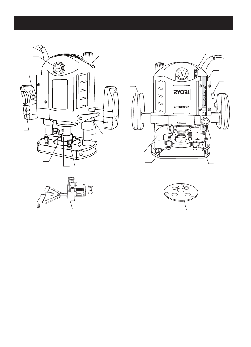
FEATURES
16
15
2
1
4
5
3
19
14
18
13
6
5
7
17
12
11
10
9
8
1. On/Off Switch
2. Lock-on Button
3. Collet
4. Router Base
5. Locking Bolts For Parallel Fence
6. Dust Port
7. Spindle Lock
8. Adjustable Depth Stop
9. Locking Bolt For Depth Stop
10. Depth Stop Adjustment Knob
11. Depth Stop
12. Speed Selector
13. Plunge Lock Lever
14. Fine Adjustment Knob
15. Carbon Brush Holder
16. Cord Sleeve
17. Template Guide
18. Handle
19. Parallel Guide
Page 2
Page 4

APPLICATIONS
T
L
Use your router only for the purposes listed below:
Routing grooves, shaping edges, freehand designs, etc.
in wood.
Chamfering, rebating, dadoing and dovetailing in wood.
Routing edges on laminates.
FEATURES
Your plunge router is a versatile woodworking tool that will
give you years of trouble-free performance. It is engineered
with the professional in mind, but its ease of operation allows
the amateur to produce work that is beautiful and precise.
As the name implies your plunge router can be used for
making plunge cuts in work pieces, routing grooves, edge
routing, routing circles and freehand routing. When used
with recommended accessories, such as router table, depth
adjustment knob and parallel guide, it becomes even more
versatile. Various types of cutters, both with and without roller
bearings as guides also add to the versatility of this tool.
HEAVY DUTY MOTOR
Your router has a powerful motor with sufcient power to
handle tough routing jobs. It delivers high power for heavy
duty performance.
DEPTH STOP SYSTEM
The adjustable depth stop located on the base of your router
provides precise stops for repetitive depth of cut changes. A
depth adjustment scale makes quick adjustments to depth of
cut changes possible.
SPINDLE LOCK
A spindle lock secures the spindle so that only one wrench
is needed to loosen the collet nut and to change the cutters.
NOTE: Do not run router with spindle lock engaged.
ON/OFF SWITCH
Your router starts and stops by depressing the on/off switch
located on the handle. Push the switch down to start the router.
Always ensure you are holding the router properly before
depressing the switch to turn the tool on. To turn the router
off, simply depress the switch again.
VARIABLE SPEED CONTROL
Your router has advanced electronic features, designed to
assist you in getting the maximum use from your router. By
making proper speed selections, your router can be adjusted
to specic routing needs. This eliminates much of the guess
work previously needed to perform operations on router tables
when used with the optional depth control knob.
The electronic feature of your router introduces the exibility
of adjusting the motor speed to required job conditions. An
electronic speed control module senses the load applied
to the motor and increases or decreases motor voltage to
compensate for and maintain desired RPM.
Speed can be set according to the approximate cutter diameter
you will be using and to the hardness of the material being
cut. The best cuts are made when the cutter is fed through
material at the proper rate of feed.
PLUNGE LOCK LEVER
After extended use, the plunge lock may wear. If this happens,
you can easily adjust the lever.
TO ADJUST PLUNGE LOCK LEVER
PLUNGE LOCK LEVER SHOWN AFTER EXTENDED
WEAR (
UNPLUG YOUR ROUTER.
Fig
. 1)
FEATURES
PLUNGE LOCK LEVER SHOWN IN ORIGINAL LOCKED
POSITION (
WARNING:
Failure to unplug your router could result in
accidental starting causing serious injury.
Your router has a plunge lock lever that allows for free
plunging. This feature is very useful for table mounted
operations on router tables when used with the optional
depth control knob. Unlocking the plunge lock lever allows
for a smooth, precise plunging action. Once you reach the
desired depth of cut, simply lock the plunge lock lever. The
cutter will then be secured at the desired depth of cut.
Fig
. 2)
Make sure lever is in locked position. (
Remove (L) the screw supporting the plunge lock lever.
Remove the lever.
Place the lever back in the original locked position.
Replace (T) the screw.
Check for free plunge with lever rotated to unlocked
position. If router does not plunge freely, reposition
lever.
Fig
. 3)
WARNING:
Your router should never be connected to power supply
when you are assembling par ts, making adjustments,
installing or removing cutters or when not in use.
Disconnecting your router will prevent accidental starting
that could cause serious injury.
Page 3
Fig. 1
Fig. 2
Fig. 3
Page 5

QUICK SELECT OF DEPTH OF CUT ( Fig. 6&7)
Use the adjustable depth stop for quick select pre-set cutting
depth positions. The position right below the depth stop
denes the cutting depth.
Lift the adjustable depth stop from its current xing point and
turn the desired cutting depth position to the position below
the depth stop.
Make sure the adjustable depth stop is secured in the xing
point.
Follow the instruction below for setting depth of cut.
WARNING:
Fa ilu re to unp lug you r rou ter cou ld re sul t in
accidental starting causing serious injury.
0
1
2
3
4
7
1
1
12
CUTTER INSTALLATION (
Fig
. 4&5)
UNPLUG YOUR ROUTER.
WARNING:
Failure to unplug your rout er cou ld result in
accidental starting causing serious injury.
CAUTION:
To prevent damage to the spindle or spindle lock,
always allow motor to come to a complete stop
before engaging spindle lock.
Depress spindle lock.
Lay router down on work bench in order to gain easy
access to collet nut .
Place the wrench provided through front of router base
onto collet nut and turn counterclockwise to loosen.
WARNING:
If you are changing a cutter immediately after use,
be careful not to touch the cutter or collet with your
hands or ngers. They will get burned because of the
heat build up from cutting. Always use the wrench
provided.
Install router bit once collet nut is loose. If changing bits,
the bit already installed will easily slip from collet after
loosening the collet nut. NOTE: The collet is machined to
precision tolerances to t bits with 12.7 mm (1/2”) diameter
shanks. To use bits with 6.35 mm ( 1/4”) diameter shanks,
insert the 6.35 mm ( 1/4”) collet adaptor into the 12.7 mm
(1/2”)collet.
Tighten the collet nut securely by turning clockwise with
the wrench provided.
Release spindle lock.
WARNING:
If the collet nut is not securely tightened, the cutter may
detach during use causing serious personal injury.
WARNING:
Do not use cutters with undersized shanks. Undersized shanks will not tighten properly and could be
thrown from the tool causing injury.
WARNING:
Do not use cutters that are larger in diameter than the
opening in router base. Use of such cutters will come in
contact with the router base and damage both the cutter
and router base. This situation could also cause possible
loss of control or create other hazardous conditions that
could cause possible serious personal injury.
Page 4
ADJUSTMENTS
Fig. 4
Fig. 5
Fig. 6
Page 6

ADJUSTING DEPTH STOP
Unplug your router.
Loosen the locking bolt for depth stop and release the
plunge lock lever.
Push the machine so far down that the router touches the
work piece and fasten the plunge lock lever.
Rotate depth stop adjustment knob to turn the depth
downwards as far as possible.
Move the pointer if necessary. It indicates zero value on
the scale.
MOUNTING AND ADJUSTING PARALLEL GUIDE
(Fig.10~12)
The parallel guide is used for straight cuts along a work piece
with a straight edge that can be followed.
0
1
2
3
4
7
1
1
12
SETTING DEPTH OF CUT
Unplug your router.
Loosen the locking bolt for depth stop and release the
plunge lock lever.
S
et the depth stop to required cutting depth with scale
indication and tighten the locking bolt.
Push the machine do
wn to the depth stop.
T
urn t he fine adjustment knob for fine adjustment of
cutting depth.
Tur n the nut to set the variable cutting depth.
Fasten the plunge lock lever.
DEPTH STOP (
Fig
. 8&9)
The depth stop is located on the base of your router and makes
it possible to make deep or heavy cuts in successive passes
by use of the Adjustable Depth Stop System. Alignment marks
make depth of cut changes quick and easy.
A preset cutting depth is achieved by plunging router until stop
bar comes in contact with depth stop. The micro-adjusting
feature provides alignment marks at each 90˚ rotation of the
depth stop knob. Each 90˚ rotation of the knob changes depth
of cut setting 0.75 mm.
A
complete rotation (360˚) of the depth stop knob changes the
depth of cut setting 3 mm.
The
Adjustable Depth Stop System provides for depth of cut
changes to be made from 0 to 12 cm from the initial setting
of the stop bar.
This initial setting of the stop bar can be “zero” depth of cut or
it can be any depth of cut setting that you choose as a star ting
point for a particular job to be performed.
WARNING:
Always wear safety goggles or safety glasses with
side shields when using your router. Failure to do so
could result in dust, shavings, chips, loose particles
or foreign objects being thrown in your eyes resulting
in possible serious injur y. If the operation is dusty,
also wear a face or dust mask.
WARNING:
Failure to unpl ug you r router cou ld res ult in
accidental starting causing serious injury.
Page 5
0
1
2
3
4
7
1
1
12
ADJUSTMENTS
0
1
2
3
4
7
1
1
12
Fig. 7
Fig. 8
Slide the guide rods in corresponding holes and tighten
the locking bolts.
Slide the parallel guide in the router base and tighten the
locking bolts.
Set the parallel guide to the desired guide distance.
For ne adjustment of guide distance, turn ne
adjustment knob.
Fig. 9
Page 7

ADJUSTMENTS
Fig. 10
Fig. 11
Fig. 12
MOUNTING TEMPLATE GUIDE (Fig. 13&14)
The template guide can be tted to the router base to accurately
duplicate curves and other complex shapes. These shapes
can be easily made by using a jigsaw to cut out the required
designs.
Place the template guide in the recess provided in the
base and tighten screws.
The guide protrudes below the bottom of the base allowing
the router to follow the template.
A template must be securely xed to the work piece and a
rm pressure applied to the router at all times to ensure that
the edge of the guide accurately follows the template.
Fig. 13
Work Peice
Template
Collet Nut
Template
Guide
Router Base
Fig. 14
ROUTING (Fig. 15)
For ease of operation and maintaining proper control, your
router has two handles, one on each side of the router
When using your router, hold it rmly with both hands.
Before starting the router, unplug it and make sure the cutter
base.
is securely tightened in collet nut and that depth of cut is
properly set.
Plug router into power supply, turn it on and let motor build
to its full speed, then gradually plunge or feed cutter into
workpiece. Do not let the cutter contact workpiece before
turning on the router and allowing it to develop full speed.
Remain alert and watch what you are doing. Do not operate
router when fatigued or under the inuence of drugs, alcohol
or any medication.
0
1
2
3
4
7
11
12
Fig. 15
Page 6
Page 8

ADJUSTMENTS
0
1
2
3
4
7
11
12
ROUTING GROOVES (
Fig
. 16)
When routing across the face of boards, set router at
desired depth of cut, place the edge of router base against
workpiece and turn on the router. Slowly feed the cutter into
the workpiece along desired line of cut.
WARNING:
If desired depth of cut is greater than can be safely
cut in one pass, make cuts in two or more passes.
When routing straight cuts across stock, clamp a straight edge to
the workpiece to use as a guide. Position the straight edge parallel
to the line of cut and offset the distance between the cutting edge
of the cutter and the edge of the router base. Hold the router base
against the straight edge and rout the groove.
When routing a groove wider than the diameter of the cutter, clamp
a straight edge on both sides of the cutlines. Position both guides
parallel to the desired line of cut and spaced equal distances
from the desired edges of the groove. Rout along one guide; then,
reverse direction and rout along the other guide.
remaining waste in the center of the groove freehand.
Clean out any
Fig. 16
30
31
Fig. 17
33
32
33
32
Fig. 18
DEPTH OF CUT (
As previously mentioned, the depth of cut is important because it
affects the rate of feed that, in turn, affects the quality of the cut
(and also the possibility of damage to your router motor and bit).
A deep cut requires a slower feed than a shallow one and a too
deep cut will cause you to slow the feed so much that the bit is
no longer cutting, it is scraping, instead.
Making a deep cut is never advisable. The smaller bits are easily
broken off when subjected to too much side thrust. A large enough
bit may not be broken, but if the cut is too deep a rough cut will
result - and it may be very difcult to guide and control the bit as
desired. For these reasons, we recommed that you do not exceed
3.2 mm depth of cut in a single pass regardless of the bit size or
the softness or condition of the workpiece.
To make deeper cuts it is therefore necessary to mark as many
successive passes as required, lowering the bit 3.2 mm for each
new pass. In order to save time, do all the cutting necessary at one
depth setting, before lowering the bit for the next pass. This will also
assure a uniform dept when the nal pass is completed.
Fig
. 17&18)
Page 7
Page 9

RYOBI TECHNOLOGIES AUSTRALIA PTY. LTD.
GUARANTEE
RYOBI TECHNOLOGIES AUSTRALIA PTY. LTD.
A.B.N. 98 002 277 509
SYDNEY: 359-361 Horsley Road, Milperra, N.S.W. 2214.
Contact during normal business hours.
Tel: (02) 9792 9888 - Fax: 1800 807 993 - www.ryobi.com.au
RYOBI NEW ZEALAND PTY. LTD.
AUCKLAND: 27 Clemow Drive, Mt Wellington, N.Z.
Tel: (09) 573 0230 - Free Call: 0800 279 624 - Fax: (09) 573 0231 - www.ryobi.co.nz
Contact during normal business hours.
Subject to the guarantee condition below, this Ryobi tool
(hereinafter called “the product”) is guaranteed by Ryobi
(hereinafter called “the Company”) to be free from
defects in material or workmanship for a period of 24
months from the date of original purchase covering
both parts and labo ur. Under the terms of this
guarantee, the repair or replacement of any part shall
be the opinion of the Company or its authorised agent.
Should service become necessary during the warranty
period, the owner should contact the Authorised Ryobi
Retailer from whom the Product was purchased, or the
nearest Company Branch Ofce. In order to obtain
guarantee service, the owner must present the sales
docket and Guarantee Certicate to conrm date of
purchase. This product is sold by the dealer or agent
as principal and the dealer has no authority from
the Company to give any additional guarantee on
the Company’s behalf except as herein contained or
herein referred to.
Guarantee Conditions
This guarantee only applies provided that the Product
has been used in accordance with the manufacturer’s
recommendations under normal use and reasonable
care (in the opinion of the Compa ny) and such
guarantee does not cover damage, malfunction or
failure resulting from misuse, neglect, abuse, or
used for a purpose for which it was not designed
or is not suited and no repai rs, alteratio ns or
modic ati ons have been attempted by other than
an Authorised Service Agent. This guarantee will not
apply if the tool is damaged by accident or if repairs
arise from normal wear and tear.
The Company accepts no additional liability pursuant to
th is g ua ra ntee for the cost s of t ra ve ll in g or
transportation of the Product or parts to and from the
service dealer or agent - such costs are not included
in this guarantee.
Certain legislation, including the Trade Practices Act,
1974 (as amended) and other state and territorial laws
give rights to the buyer and impose liability on the seller
in certain circumstances. Nothing herein shall have the
effect of excluding, restricting or modifying any
condition, guarantee, right or liability imposed, to the
extent only th at such exclusion, r est riction o r
modication would render any term herein void.
BRISBANE: All enquiries Tel : 1300 361 505
TOWNSVILLE: All enquiries Tel : 1300 361 505
MELBOURNE: 960 Stud Road, Rowville,Vic. 3178
Tel : (03) 9764 8655
HOBART:
All enquiries Tel : 1300 360 216
ADELAIDE:
All enquiries Tel : 1300 360 216
PERTH:
33-35 Sorbonne Cres., Canning Vale,W.A. 6155.
Tel : (08) 9455 7775
Purchased From
Address Of Dealer
Date Model No Serial No
This Guarantee Form Should Be Retained By The Customer At All Times
For your record and to assist in establishing date of purchase (necessary for in-guarantee service)
please ke ep you r p urchase docket and thi s f orm completed with the fo llo win g particulars.
Present This Form With Your Purchase Docket When Guarantee Service Is Required.
 Loading...