

Page 1
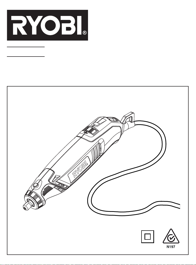
EHT150RG
ROTARY TOOL
OWNER’S OPERATING MANUAL
Page 2
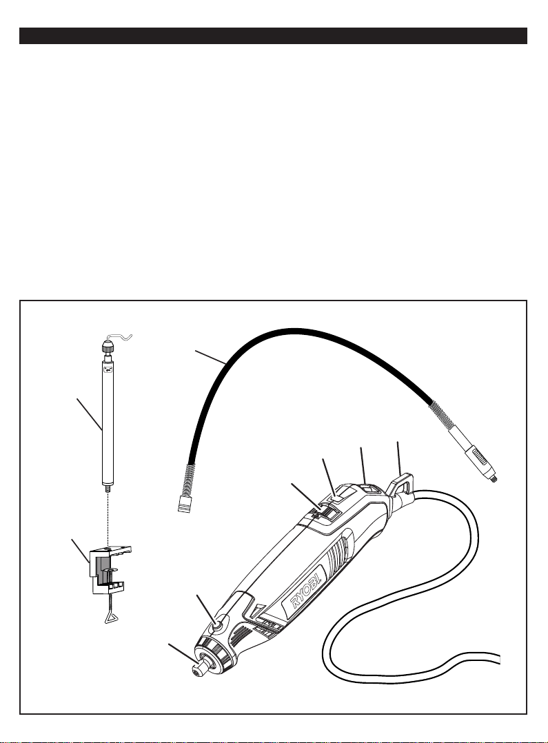
1. Collet nut
2. Spindle lock
3. Speed control dial
4. On/off switch
5. Tool loop
6. Collet
7. Wrench
8. Accessory
9. Spindle
10. Grinding wheel bits
11. Rubber polishing bits
12. Mandrel screw
13. Washer
14. Cut-off disk
15. Mandrel
16. Tighten
17. Fiberglass cut-off wheel
18. Sanding drums
19. Indicator mark
23
DESCRIPTION
20. Less speed
21. More speed
22. Pencil holding method
23. Telescoping tool hanger
24. Flex shaft
25. Clamp-on base
26. Tool hanger hook
27. T ool hanger
28. Clamp screw
29. Drive shaft
30. Collar
31. Cup end of fl ex shaft
32. Locking key
33. Hole
34. Grooved gripping section
35. Live tool indicator
36. Collet sleeve
37. T ool head
24
5
4
35
3
25
2
1
Fig. 1
Page 3
3
35
4
7
2
6
1
8
1
6
9
2
Fig. 2
Fig. 3
Fig. 4
12
14
13
10
2
15
1
11
16
6
Fig. 5
17
19
Fig. 6
Fig. 7
3
18
20
21
22
Fig. 8
Fig. 9
Fig. 10
Page 4
26
5
36
25
27
28
29
30
24
31
Fig. 11 Fig. 12
33
1
7
32
34
6
1
9
2
37
Fig. 13 Fig. 14
Page 5

Important!
It is essential that you read the instructions in this manual before
operating this machine.
Subject to technical modifications.
Page 6

English
GENERAL POWER TOOL SAFETY WARNINGS
WARNING
Read all safety warnings and all instructions. Failure
to follow the warnings and instructions may result in electric
shock, fi re and/or serious injury.
Save all warnings and instructions for future
reference.
The term “power tool” in the warnings refers to your
mains-operated (corded) power tool or battery-operated
(cordless) power tool.
1. WORK AREA
a. Keep work area clean and well lit. Cluttered or
dark areas invite accidents.
b. Do not operate power tools in explosive
atmospheres, such as in the presence of
flammable liquids, gases, or dust. Power tools
create sparks which may ignite the dust or fumes.
c. Keep children and bystanders away while
operating a power tool. Distractions can cause
you to lose control.
2. ELECTRICAL SAFETY
a. Power tool plugs must match the outlet. Never
modify the plug in any way. Do not use any
adaptor plugs with earthed (grounded) power
tools. Unmodifi ed plugs and matching outlets will
reduce risk of electric shock.
b. Avoid body contact with earthed or grounded
surfaces such as pipes, radiators, ranges and
refrigerators. There is an increased risk of electric
shock if your body is earthed or grounded.
c. Do not expose power tools to rain or wet
conditions. Water entering a power tool will
increase the risk of electric shock.
d. Do not abuse the cord. Never use the cord for
carrying, pulling or unplugging the power tool.
Keep cord away from heat, oil, sharp edges
or moving parts. Damaged or entangled cords
increase the risk of electric shock.
e. When operating a power tool outdoors, use an
extension cord suitable for outdoor use. Use of
a cord suitable for outdoor use reduces the risk of
electric shock.
f. If operating power tools in a damp location
is unavoidable, use a residual current device
(RCD) protected supply. Use of an RCD reduces
the risk of electric shock.
3. PERSONAL SAFETY
a. Stay alert, watch what you are doing and
use common sense when operating a power
tool. Do not use a power tool while you are
tired or under the influence of drugs, alcohol
or medication. A moment of inattention while
operating power tools may result in serious
personal injury.
b. Use personal protective equipment. Always
wear eye protection. Protective equipment such
as dust mask, non-skid safety shoes, hard hat, or
hearing protection used for appropriate conditions
will reduce personal injuries.
c. Prevent unintentional starting. Ensure the
switch is in the off-position before connecting
to power source and/or battery pack, picking
up or carrying the tool. Carrying power tools with
your fi nger on the switch or energising power tools
that have the switch on invites accidents.
d. Remove any adjusting key or wrench before
turning the power tool on. A wrench or a key left
attached to a rotating part of the power tool may
result in personal injury.
e. Do not overreach. Keep proper footing and
balance at all times. This enables better control
of the power tool in unexpected situations.
f. Dress properly. Do not wear loose clothing or
jewellery. Keep your hair, clothing and gloves
away from moving parts. Loose clothes, jewellery
or long hair can be caught in moving parts.
g. If devices are provided for the connection of
dust extraction and collection facilities, ensure
these are connected and properly used. Use of
dust collection can reduce dust-related hazards.
4. POWER TOOL USE AND CARE
a. Do not force the power tool. Use the correct
power tool for your application. The correct
power tool will do the job better and safer at the
rate for which it was designed.
b. Do not use the power tool if the switch does not
turn it on and off. Any power tool that can not be
controlled with the switch is dangerous and must
be repaired.
c. Disconnect the plug from the power source
and/or the battery pack from the power tool
before making any adjustments, changing
accessories, or storing power tools. Such
preventive safety measures reduce the risk of
starting the power tool accidentally.
d. Store idle power tools out of the reach of
children and do not allow persons unfamiliar
with the power tool or these instructions
to operate the power tool. Power tools are
1
Page 7

English
dangerous in the hands of untrained users.
e. Maintain power tools. Check for misalignment
or binding of moving parts, breakage of parts
and any other condition that may affect the
power tools operation. If damaged, have the
power tool repaired before use. Many accidents
are caused by poorly maintained power tools.
f. Keep cutting tools sharp and clean. Properly
maintained cutting tools with sharp cutting edges
are less likely to bind and are easier to control.
g. Use the power tool, accessories and tool bits
etc., in accordance with these instructions and
in the manner intended for the particular type
of power tool, taking into account the working
conditions and the work to be performed. Use
of the power tool for operations different from
intended could result in a hazardous situation.
5. SERVICE
a. Have your power tool serviced by a qualified
repair person using only identical replacement
parts. This will ensure that the safety of the power
tool is maintained.
SPECIAL SAFETY RULES
Hold tool by insulated gripping surfaces when
performing an operation where the cutting tool
may contact hidden wiring or its own cord. Contact
with a “live” wire will make exposed metal parts of the
cutting tool “live” and shock the operator.
Inspect for and remove all nails from lumber
before using this tool. Following this rule will reduce
the risk of serious personal injury.
Do not reach in the area of the spinning bit. The
proximity of the spinning bit to your hand may not
always be obvious.
This product is not intended for use as a dental drill
or in human or veterinary medical applications.
Serious injury may result.
When using steel screws, cut-off wheels, high
speed cutters, or tungsten carbide cutters, always
have the work securely clamped. Never attempt to
hold the work with one hand while using any of
these accessories.
This appliance is not intended for use by persons
(including children) with reduced physical,
sensory or mental capabilities, or lack of
experience and knowledge, unless they have been
given supervision or instruction concerning use
of the appliance by a person responsible for their
safety. Children should be supervised to ensure
that they do not play with the appliance.
This appliance is not intended for use by young
children or infirm persons. Adequate supervision by a
responsible person must be provided to ensure that
they do not play with the appliance.
Keep children and visitors away. Visitors should
wear safety glasses and be kept a safe distance from
work area. Do not let visitors contact tool or extension
cord.
Complies with AS/NZS 60745.
Recommended for the use of a residual current device
with a rated residual current of 30 mA or less.
ELECTRICAL
DOUBLE INSULATION
Double insulation is a concept in safety in electric power
tools, which eliminates the need for the usual three-wire
grounded power cord. All exposed metal parts are isolated
from the internal metal motor components with protecting
insulation. Double insulated tools do not need to be
grounded.
WARNING
The double insulated system is intended to protect
the user from shock resulting from a break in the
tool’s internal insulation. Observe all normal safety
precautions to avoid electrical shock.
NOTE: Servicing of a product with double insulation
requires extreme care and knowledge of the system and
should be performed only by a qualifi ed service technician.
For service, we suggest you return the product to your
nearest authorized service center for repair. Always use
original factory replacement parts when servicing.
ELECTRICAL CONNECTION
This product has a precision-built electric motor. It should
be connected to a power supply that is 230 volts, AC only
(normal household current), 60 Hz. Do not operate this
product on direct current (DC). A substantial voltage drop
will cause a loss of power and the motor will overheat. If
the product does not operate when plugged into an outlet,
double-check the power supply.
EXTENSION CORDS
When using a power tool at a considerable distance
from a power source, be sure to use an extension cord
that has the capacity to handle the current the product
will draw. An undersized cord will cause a drop in line
voltage, resulting in overheating and loss of power. Use
the chart to determine the minimum wire size required in
an extension cord.
When working outdoors with a product, use an extension
2
Page 8

English
cord that is designed for outside use.
WARNING
Some dust created by power sanding, sawing, grinding,
drilling, and other construction activities contains
chemicals known to cause cancer, birth defects or other
reproductive harm. Some examples of these chemicals
are:
lead from lead-based paints
crystalline silica from bricks and cement and
other masonry products, and
arsenic and chromium from chemically-treated
lumber
Your risk from these exposures varies, depending on
how often you do this type of work. To reduce your
exposure to these chemicals: work in a well ventilated
area, and work with approved safety equipment, such
as those dust masks that are specially designed to fi lter
out microscopic particles.
SPECIFICATIONS
Input 240 V 50 Hz
No-load speed 10,000-35,000 (RPM) min
Collet 3.2 mm max.
Weight 0.54 kg
-1
OPERATION
WARNING
Do not allow familiarity with products to make you
careless. Remember that a careless fraction of a
second is suffi cient to infl ict serious injury.
WARNING
Always wear eye protection marked to comply with
ANSI Z87.1. Failure to do so could result in objects
being thrown into your eyes resulting in possible
serious injury.
WARNING
Do not use any attachments or accessories not
recommended by the manufacturer of this product. The
use of attachments or accessories not recommended
can result in serious personal injury.
APPLICATIONS
You may use this product for the purposes listed below:
Cutting
Sanding
Polishing and buffing
Engraving
Drilling
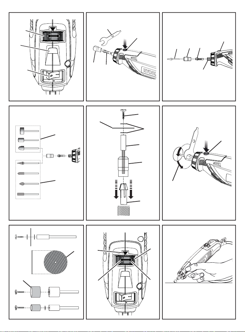
TURNING THE ROTARY TOOL ON/OFF
See Figure 2.
To turn the tool on: Push “ | ”.
To turn the tool off: Push “ O ”.
CAUTION
To prevent damage to the spindle or spindle lock,
always allow motor to come to a complete stop before
engaging the spindle lock.
CHANGING COLLETS
See Figure 3.
Unplug the rotary tool.
Press and hold the spindle lock, and rotate the shaft
with the provided collet wrench until the spindle lock
engages the shaft, preventing further rotation.
With the spindle lock engaged, use the collet wrench
to loosen the collet nut, if necessary.
Remove the collet nut and old collet using collet
wrench, if necessary.
Insert the unslotted end of the collet in the hole in the
end of the tool shaft.
Replace the collet nut on the shaft.
WARNING
Always use the collet which matches the shank size
of the accessory you plan to use. Never force a large
diameter shank into a collet. The accessory should
fi t smoothly into the collet, but you should be able to
tighten the accessory fi rmly and securely with the
provided wrench.
DANGER
If you are changing an accessory immediately after
use, be careful not to touch the collet, collet nut, or
the accessory with your hands or fi ngers. You will
get burned because of the heat build-up from cutting.
Always use the wrench provided.
3
Page 9

English
INSTALLING ACCESSORIES
See Figures 4 - 5.
Unplug the rotary tool.
Press and hold the spindle lock, and rotate the shaft
by hand until the spindle lock engages the shaft,
preventing further rotation.
With the spindle lock engaged, use the collet wrench
to loosen the collet nut, if necessary.
Insert the shank of the accessory into the collet until
the shank bottoms out, then pull it out 1.6 mm (1/16 in)
to allow for expansion when the accessory gets hot.
With the spindle lock engaged, tighten the collet nut
with the provided wrench until the accessory shank is
gripped by the collet. Avoid excessive tightening of the
collet nut.
REMOVING ACCESSORIES
See Figures 4 - 5.
Unplug the rotary tool.
With the spindle lock engaged, loosen the collet nut
with the provided wrench.
Remove the accessory.
USING MANDRELS
See Figures 6 - 8.
The most common types of mandrel to use with this tool
are the standard mandrel which is used with cut-off discs,
grinding wheels, emery wheels, and cut-off wheels. Screw
mandrels are used with polishing wheels and polishing
drums. Drum mandrels are used with sanding drums.
To install:
Unplug the rotary tool.
Install the mandrel.
If using the standard mandrel:
Press and hold the spindle lock.
Insert the slot end of the provided wrench into the slot
on top of the mandrel and unscrew.
Remove mandrel screw and washer.
Place desired accessory over mandrel shaft and align
accessory hole with mandrel hole.
Insert mandrel screw with washer through the
accessory and mandrel shaft holes.
NOTE: The mandrel washer should be placed between
the mandrel screw and the accessory.
Tighten using provided wrench.
If using the screw mandrel:
Align desired accessory hole with mandrel screw
head.
Screw accessory onto mandrel by twisting clockwise
until secure.
If using the drum mandrel:
Align appropriately sized sanding drum over mandrel
and push down to completely cover drum end of
mandrel.
NOTE: If necessary, tighten the screw on the drum
mandrel head to expand the drum and securely hold the
sanding drum in place.
BALANCING ACCESSORIES
For precision work, it is important that all accessories
be properly balanced. To balance an accessory, slightly
loosen the collet nut and give the accessory or collet a
6.35 mm (1/4 in) turn. You should be able to tell by the
sound and feel if the accessory is running in balance.
Continue adjusting in this fashion until the best balance is
achieved. Replace accessories if they become damaged
or unbalanced.
SELECTING THE RIGHT SPEED
See Figure 9.
The rotary tool has a speed range of 10,000 to 35,000
RPM. T o select the right speed for each job, use a practice
piece of material. Vary speed to fi nd the best speed for the
accessory you are using and the job to be done.
Use the indicator mark above the speed control dial to
set the best speed for the job. The speed control dial is
numbered 1 to 5 and MAX. For example, a speed setting
of 1 is approximately 10,000 RPM, and a speed setting of
MAX is approximately 35,000 RPM.
Refer to the speed dial settings table to determine the
proper speed based on the material being worked and the
type of accessory being used.
SLOWER SPEEDS
Certain materials, some plastics for example, require
a relatively slow speed because the friction of the tool
generates heat and causes the plastic to melt at high
speed.
Slow speeds (15,000 RPM or less) are usually best for
polishing operations using the polishing accessories. They
may also be best for working on delicate projects, delicate
wood carving, and fragile model parts.
Higher speeds are better for carving, cutting, and shaping
wood. Hardwoods, metals, and glass require high speed
operation. Drilling should also be done at high speeds.
To determine the optimum operational speed for different
4
Page 10

English
materials and accessories, refer to the speed dial settings
table. Look this table over and become familiar with it.
The best way to determine the correct speed for work on
any material is to practice for a few minutes on a piece of
scrap, even after referring to the table. You can quickly
learn whether a slower or faster speed is more effective
just by observing what happens when you make a pass or
two at different speeds.
When working with a scrap piece of plastic, start from
a slow rate of speed and increase the speed until you
observe the plastic is melting at the point of contact;
reduce the speed slightly to get optimum working speed
without melting the workpiece.
NOTE:
Plastic and materials that could melt at slow
temperatures should be cut at low speeds.
Soft wood should be cut at high speed.
Aluminum, tin, copper, lead, and zinc alloys may be
cut at any speed, depending on the type of cutting
being done. Use paraffin or other suitable lubricant on
the cutter to prevent the cut material from adhering to
the cutter teeth.
For more information, see table on speed dial settings.
OPERATING THE ROTARY TOOL
See Figure 10.
Learning to use the rotary tool:
Hold the tool in your hand and get used to its weight,
balance, and the taper of the housing. This taper
permits the tool to be grasped like a pencil.
Examine the rotary tool accessories carefully.
Damaged accessories can fly apart as they come up
to speed and should not be used. The use of damaged
accessories can result in serious personal injury.
Practice on scrap materials first to see how the tool
operates. Keep in mind that the work is done by the
speed of the tool and by the accessory in the collet.
You should not lean on or push the tool into the work.
It is best to make a series of passes with the tool rather
than attempt to do all the work in one pass. To make a
cut, pass the tool back and forth over the work like you
would a small paint brush. Cut a little material on each
pass until you reach the desired depth. For most work, a
gentle touch is best; you will have greater control, make
fewer errors, and get the most effi cient work out of the
accessory.
For the best control in close work, grip the tool like a pencil
between your thumb and forefi nger. A “hand grip” method
of holding the tool is used for operations such as grinding
a fl at surface or using cut-off discs.
To operate the rotary tool:
Secure all work in a vise or clamp to a workbench to
prevent it from moving under the tool.
Hold the tool in front and away from you, keeping the
tool accessory clear of the workpiece.
Turn on the tool and let the motor and accessory build
up to full speed.
Lower the tool gradually until the accessory contacts
the workpiece.
Move the tool continuously at a steady, consistent
pace.
Use just enough pressure to keep the tool from
chattering or bouncing.
NOTE: Heavy pressure will decrease the tool’s speed and
put a strain on the motor. The weight of the tool alone is
adequate for most jobs.
Lift the tool away from the workpiece before turning
off the tool.
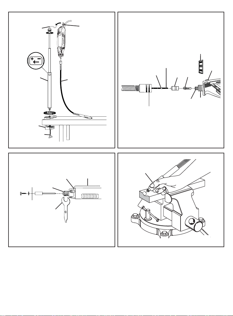
TELESCOPING TOOL HANGER WITH CLAMP ON
BASE
See Figure 11.
The telescoping tool hanger provides a convenient place
to hang the rotary tool while the fl ex shaft is in use.
To clamp the base to a worktable:
Turn the clamp screw counterclockwise to open the
clamping area.
Place clamp over the edge of worktable.
Turn the clamp screw clockwise until the clamp is
secure.
To attach the tool hanger to the base:
Turn the lower part of the tool hanger clockwise to
unlock.
Pull the tool hanger up to lengthen or push the tool
hanger down to shorten its height.
Turn the lower part of the tool hanger counterclockwise
to lock into place.
Screw the tool hanger into the top of the clamp.
NOTE: When using the fl ex shaft, hang the rotary tool on
the tool hanger hook using the hook located on the back
of the rotary tool.
OPERATING THE FLEX SHAFT
See Figures 12 - 14.
The 1/8 in. collet must be inserted into the rotary tool
before the fl ex shaft can be installed. To install the fl ex
shaft:
5
Page 11

English
Unplug the rotary tool.
Loosen collet sleeve by turning counterclockwise, then
remove.
Press and hold the spindle lock, and rotate the shaft
by hand until the spindle lock engages the shaft,
preventing further rotation.
With the spindle lock engaged, use the collet wrench
to loosen the collet nut, if necessary.
Remove collet nut and collet.
Insert the 1/8 in. collet.
Replace and tighten the collet nut.
Insert drive shaft into collet nut until the collar meets
the collet nut.
Tighten the collet nut completely, keeping collar in
contact with the collet nut.
Insert cup end of flex shaft onto tool head. Turn
clockwise to tighten.
To install accessories into the fl ex shaft:
Unplug the rotary tool.
Locate the hole behind the collet nut in the flex shaft
body.
Turn the collet nut until the hole in the flex shaft body
aligns with the hole visible inside the flex shaft.
Insert provided locking key into the aligned holes to
lock collet nut into place.
Insert the shank of the accessory into the collet nut
until the shank bottoms out, then pull it out 1/16 in. to
allow for expansion when the accessory gets hot.
With the key still in place, tighten the collet nut with the
provided wrench until the accessory shank is gripped
by the collet. Avoid excessive tightening of the collet
nut.
Remove the key.
To remove accessories from the fl ex shaft:
Unplug the rotary tool.
Locate the hole behind the collet nut in the flex shaft
body.
Turn the collet nut until the hole in the flex shaft body
aligns with the hole visible inside the flex shaft.
Insert provided locking key into the aligned holes to
lock collet nut into place.
With the key still in place, loosen the collet nut with the
provided wrench.
Remove the accessory.
To operate the rotary tool using the fl ex shaft:
Secure all work in a vise or clamp to a workbench to
prevent it from moving under the tool.
Grip the flex shaft along the grooved gripping section.
Hold the tool in front and away from you, keeping the
tool accessory clear of the workpiece.
Turn on the tool and let the motor and accessory build
up to full speed.
Lower the tool gradually until the accessory contacts
the workpiece.
Move the tool continuously at a steady, consistent
pace.
Use just enough pressure to keep the tool from
chattering or bouncing.
NOTE: Heavy pressure will decrease the tool’s speed and
put a strain on the motor. The weight of the tool alone is
adequate for most jobs.
Lift the tool away from the workpiece before turning
off the tool.
LIVE TOOL INDICATOR
This tool features a live tool indicator which illuminates as
soon as the tool is connected to the supply. This warns the
user that the tool is connected and will operate when the
switch is pressed.
MAINTENANCE
WARNING
When servicing, use only identical replacement parts.
Use of any other part may create a hazard or cause
product damage.
Avoid using solvents when cleaning plastic parts. Most
plastics are susceptible to damage from various types of
commercial solvents and may be damaged by their use.
Use clean cloths to remove dirt, dust, oil, grease, etc.
WARNING
Do not at any time let brake fl uids, gasoline, petroleum-
based products, penetrating oils, etc., come in contact
with plastic parts. They contain chemicals that can
damage, weaken or destroy plastic.
Do not abuse power tools. Abusive practices can damage
tool as well as workpiece.
6
Page 12

English
WARNING
Do not attempt to modify this tool or create accessories
not recommended for use with this tool. Any such
alteration or modifi cation is misuse and could result
in a hazardous condition leading to possible serious
personal injury.
Electric tools used on fi berglass material, wallboard,
spackling compounds, or plaster are subject to
accelerated wear and possible premature failure because
the fi berglass chips and grindings are highly abrasive to
bearings, brushes, commutators, etc. Consequently, we
do not recommend using this product for extended work
on these types of materials. However, if you do work with
any of these materials, it is extremely important to clean
the product using compressed air.
LUBRICATION
All of the bearings in this product are lubricated with a
suffi cient amount of high grade lubricant for the life of
the unit under normal operating conditions. Therefore, no
further lubrication is required.
POWER SUPPLY CORD REPLACEMENT
If replacement of the power supply cord is necessary, this
must be done by an authorized service center in order to
avoid a safety hazard.
SYMBOL
Safety Alert
V Volts
Hz
Hertz
Alternating Current
W
Watts
no
No-load speed
-
1
Revolutions or reciprocations per minute
min
Please read the instructions carefully before
starting the machine.
Waste electrical products should not be
disposed of with household waste. Please
recycle where facilities exist. Check with your
Local Authority or retailer for recycling advice.
Conformity
Double insulation
Wear ear protection
Wear eye protection
7
Page 13

English
SPEED DIAL SETTINGS
Type of
Accessory
Cut-off
Discs
Fiberglass
Cut-off
Wheel
Sanding
Drums
Felt
Polishing
Wheels
Aluminum
Oxide
Grinding
Stones
Silicon
Carbide
Grinding
Stone
Drill Bit 4-MAX 4-MAX 1-3 4-MAX 4-MAX — — —
Drywall
Cutting Bit
Soft Wood
— — — 1-3 — — — —
— — 1-3 — 1-5 — — —
3-MAX 3-MAX 1-3 4-MAX 4-MAX — — —
— — — 3-5 3-5 3-5 3-5 3-5
— — — 3-5 — — — —
— — — — 1-2 1-2 4-MAX 4-MAX
Hard
Wood
Laminates
Plastics
Steel
4-MAX (Drywall only)
Aluminum,
Brass, Etc.
Shell/
Stone
Ceramic Glass
8
Page 14

English
ACCESSORY TABLE
Figure Qty Accessory Application
1 1/8 in. Collet
1 1/16 in. Collet
Attaching Bits
Orange 120-Grit Aluminum Oxide
3
Grinding Wheel Bits
Green 120-Grit Silicon Carbide Grinding
1
Wheel Bit
1 1/4 in. Drum Sander Mandrel
1 1/2 in. Drum Sander Mandrel
1 Polishing Compound Vial
72 15/16 in. X 1/32 in. Cut-off Discs Cutting ferrous materials
3/4 in. Pink 220-Grit Aluminum Oxide
1
Grinding Wheel
1/4 in. X 1/2 in. Sanding Drums (60-Grit
8
and 120-Grit)
1/2 in. X 1/2 in. Sanding Drums (60-Grit
8
and 120-Grit)
1 Silicon Carbide Dressing Stone
3 Felt Polishing Wheels (1 in. and 1/2 in. [2])
2 1-1/4 in. Fiberglass Cut-off Wheel
1 1/8 in. Screw Mandrel Attaching felt attachments
1 Mandrel (1/8 in. shank X 1/16 in.)
2 High Speed Steel Drill Bit (1/16 in.) Drilling
Ferrous materials: casting, welds, rivets,
rust
Non-ferrous materials: stone, ceramics,
porcelain, glass
Attaching sanding drums
Polishing and brightening metals and
plastics
Ferrous materials: casting, welds, rivets,
rust
Sanding wood, metals and plastics
Bringing shape back to parabolic shaped
grinding attachments
Polishing and buffi ng metals, stone, glass
and ceramics
Cutting and trimming metals, plastics and
ceramics
Attaching cut-off discs, cut-off wheels,
grinding wheels, and emery wheels
2 1/8 in. Drywall Cutting Bit Cutting drywall
9
Page 15

English
ACCESSORY TABLE
Figure Qty Accessory Application
1 Wrench Removing attachments
1 Telescoping Tool Hanger
1 36’’ Flex Shaft
1 Clamp-on Base Attaching the tool hanger on the base
1 Locking Key
Hanging the rotary tool while using the fl ex
shaft
Allowing fi ngertip control to cut, sand,
polish, etc.
Locking the spindle of fl ex shaft to replace
the accessory
10
Page 16

7(&+7521,&,1'8675,(6$8675$/,$37</7'
/HYHO'RQFDVWHU5RDG
'RQFDVWHU9LFWRULD
$XVWUDOLD
7HO)D[1R
 Loading...