

Page 1

ETS-1526AL
TABLE SAW
OWNER’S OPERATION MANUAL
N197
THANK YOU FOR BUYING A RYOBI TABLE SAW
Your new table saw has been engineered and manufactured to Ryobi's high standard for
dependability, ease of operation, and operator safety. Properly cared for, it will give you years of rugged,
trouble free performance.
CAUTION: Carefully read through this entire owner's manual before using your
TABLE SAW.
Pay close attention to the Rules for Safe Operation, Warnings, and Cautions.
If you use your saw properly and only for what it is intended, you will enjoy years of safe, reliable
service.
Thank You again for buying Ryobi tools.
SAVE THIS MANUAL FOR FUTURE REFERENCE.
Page 2
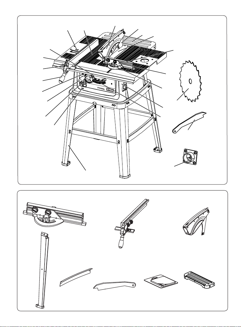
Fig. 0
C
A
D
E
F
G
21
22
15
12
1
10
9
18
17
20
7
86
11
5
19
3
14
13
2
4
B
16
24
H
Page 3
2-5mm
Fig. 1
Fig. 3 Fig. 4
Fig. 6
Fig. 2
13
15
20
7
15
20
19
5
6
Fig. 7
3
6
3
Fig. 5
Fig. 5a
24
Page 4
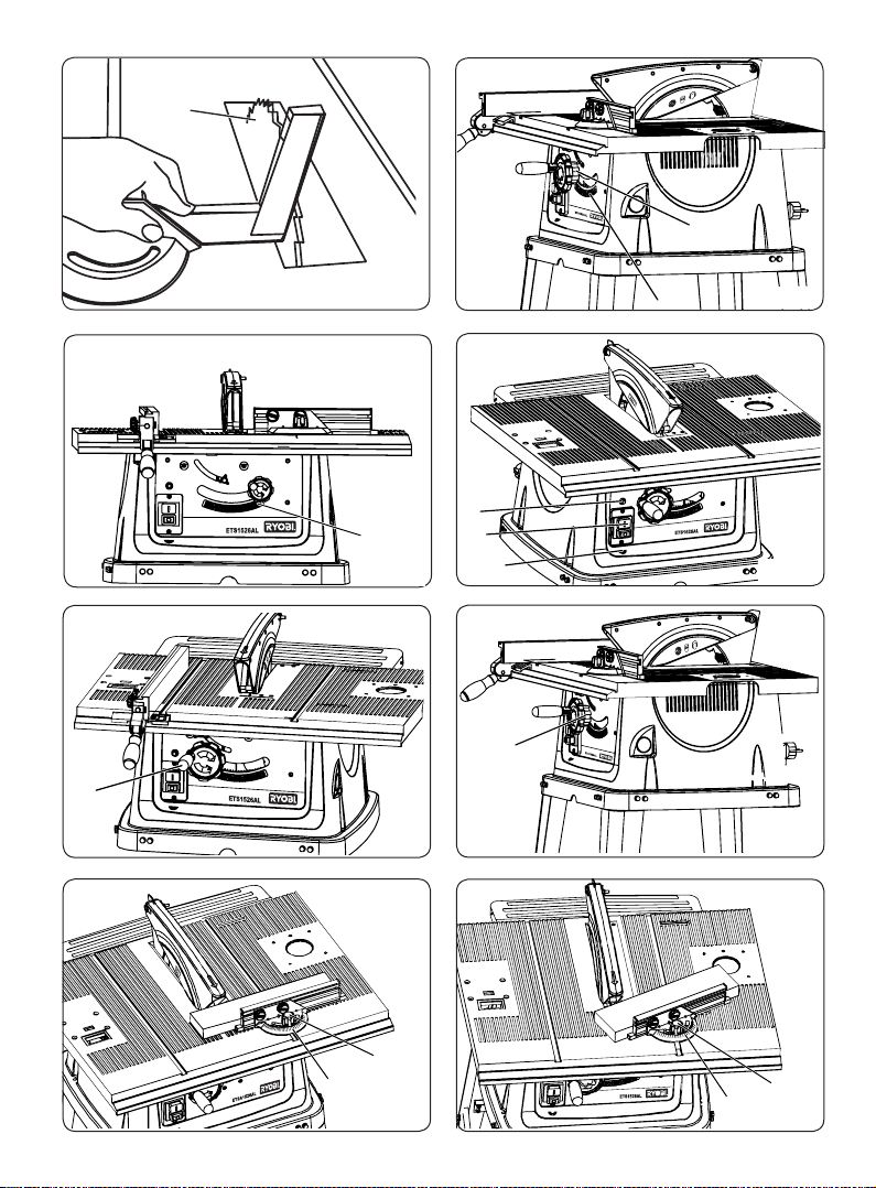
Fig. 10
Fig. 12
Fig. 13
Fig. 14
Fig. 15
12
45
o
2
13
23
9
10
10
23
Fig. 9
4
9
Fig. 11
14
Fig. 8
15
Page 5
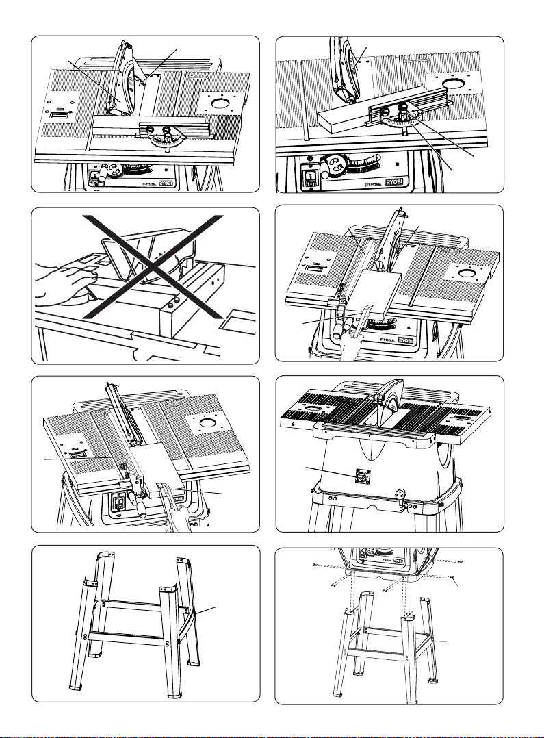
Fig. 17
Fig. 18
Fig. 19
Fig. 20
Fig. 21
Fig. 22
Fig. 16
15
15
10
9
156
16
16
6
M6
7
15
22
Fig. 23
M6
M5
Page 6

Fig. 25
Fig. 24
Page 7

Page 1
WARNING!
When using electric tools basic safety
precautions should always be followed to reduce
the risk of fire, electric shock and personal injury.
Read all these instructions before attempting to
operate your product. Save these instructions
for future reference.
Keep your work area clean and well lit.
Cluttered benches and dark areas invite
accidents.
Do not operate power tools in explosive
atmospheres, such as in the presence of
flammable liquids, gases or dust. Power
tools create sparks which may ignite dust or
fumes.
Children, visitors and pets should be kept a
safe distance from the work area.
Avoid wearing loose clothing, jewellery or
anything that could get caught in moving
parts. Long hair should be tied back. Use
of safety goggles is recommended (normal
glasses are not sufficient for eye protection).
Face or dust masks should be used if dust
is produced or working overhead. Ear
protection is advised during periods of
extended operation.
Do not overreach. Keep proper footing and
balance at all times; wear oil-resistant rubber
footwear. Keep floor clear of oil, scrap and
other debris.
Do not force the tool. Do not attempt to
use the tool for a purpose for which it was
not designed. The tool will give much better
service if you do not use excessive force.
Disconnect the plug when not in use, or when
changing accessories, making adjustments,
cleaning or working on tool. Always unplug
when leaving the tool unattended. All tools
should be kept out of the reach of children
when not in use. Do not expose the tool to
rain and moisture.
Only use accessories that are recommended
by the manufacturer of your model.
Accessories that may be suitable for one
tool may create a risk of injury when used on
another tool.
Guard
against electric shocks – avoid body
contact with earthed surface (e.g. radiators,
pipes, dishwashers, refrigerators). Hold the
tool by insulated gripping surfaces when
performing an operation where the cutting
tool may contact hidden wiring.
GENERAL SAFETY PRECAUTIONS
Make sure the cord is located so that it will
not be stepped on, tripped over or otherwise
subjected to damage or stress.
Avoid accidental start-ups, make sure that
the power switch is in “OFF” position before
plugging in the power.
Maintain tools properly. Always keep tools
clean and in good working order. Follow
instructions for lubricating and changing
accessories.
Check damaged parts. Check for alignment
of moving parts, binding of moving parts,
breakage of parts, improper mounting, or
any other condition that may affect the tools
operation. Any part that is damaged should
be properly repaired or replaced.
Never use solvents to clean plastic parts.
Solvents could possibly dissolve or otherwise
damage the material. Only a soft damp cloth
should be used to clean plastic parts.
Always use in a well ventilated area. Remove
sawdust frequently. Clean out sawdust from
the interior of the saw to prevent a potential
fire hazard.
Despite the machine being operated in
conformity with the intended conditions of
use and under observance of all relevant
safety regulations, due to the design required
by the nature of work to be carried out with it,
some residual risks remain possible. These
risks including contact with the revolving
blade in the cutting area, kickback of the
workpiece or parts thereof, breaking of
the saw blade with the broken parts being
ejected from the machine, contact with live
parts when checking electrical components
opened for inspection, emission of harmful
wooden dusts when operated without a dust
collector.
Page 8

Always hold the work firmly against the mitre
gauge or fence.
Never perform any operation “free hand”.
Always use either the fence or the mitre gauge
to position and guide.
Rebating or grooving should not be carried
out.
Saws shall not be used for slotting (stopped
groove).
Use only saw blades for which the maximum
possible speed is not less than the maximum
spindle speed of the tool and the material to
be cut.
Never stand or have any parts of your body in
line with the path of the saw blade. Keep your
hands out of the line of the saw blade.
Move the rip fence out of the way when cross
cutting.
Feed the work into the blade or cutter
AGAINST the direction of rotation only.
Never use the fence as a cut-off gauge when
crosscutting.
Never attempt to free a stalled blade without
first turning the saw OFF. Turn off the power
switch immediately to prevent motor damage.
When transporting the machine use only
transportation devices and never use guards
for handling or transportation.
During transportation the upper part of the
saw blade should be covered; for example by
the guard.
Use an extension table for supporting long
workpieces during cutting operation.
Ensure that polyfoam packaging is removed
before use.
Ensure that the yellow warning label is
removed from the table before use.
ADDITIONAL SAFETY PRECAUTIONS FOR TABLE SAW
Do not use saw blades which are damaged or
deformed.
Replace table insert when worn.
Use only saw blades recommended by the
manufacturer.
When changing the saw blade be aware that
the width of the cut will be wider than the body
of the blade,which in turn should be not be
wider than the thickness of the riving knife.
Take care that the selection of the saw blade is
suitable for the material to be cut.
Wear suitable personal protective equipment
when necessary, this could include
- hearing protection to reduce the risk of
induced
hearing loss,
- respiratory protection to reduce the risk of
inhalation of harmful dust,
- wear gloves when handling saw blades and
rough material. Saw blades shall be carried in
a holder whenever practicable.
Dust developing during operation can be
harmful to your health, inflammable or
explosive. Never cut metals or materials which
may make hazardous dust.
Do not use High speed steel blades.
Use the push stick when required. Always use
a push stick for ripping narrow timber. Refer to
ripping applications in this Instruction Manual
where use of the push stick is covered in detail.
The push stick should always be stored with
the machine when not in use.
Always use the saw blade guard and riving
knife for every operation, including through
sawing. Through sawing operations are those
in which the blade cuts completely through
the work piece when ripping or crosscutting.
Page 2
DESCRIPTION(FIG. 0)
1. Body
2. ON/OFF Switch
3.
Rip Fence Lock Handle
4.
Live Tool Indicator
5. Rip Fence Lock Knob
6. Rip Fence
7. Blade Guard
8.
Table Top
9. Mitre Gauge
10.
Mitre Gauge Lock
11. Bevel Lock Knob
12. Bevel Angle Indicator
13. Elevating Handle
14. Reset Button
15.
Saw Blade
16. Push Stick
17. Table Insert/Throat Plate
18. Mitre Fence
19. Sliding Block
20. Riving Knife
21. Stand (Optional)
22.
Dust Port
23. Tilting Handle(Fig. 9&13)
24. Rear extension table
Page 9

A: Mitre gauge assembly
B: Rip fence assembly
C:
Blade guard assembly
D: Leg stand (4pcs)
Page 3
SPECIFICATION
Input voltage 240V ~ 50Hz
Watts 1500W
Blade diameter
254mm
Bore siz
e 15.9mm
No load speed
4500min-1
Depth of cut at 90°
80mm
Depth of cut at 45°
55mm
Main tab
le size 720mm(W) x 520mm(L)
Rear extension table size 440mm(W) x 125mm(L)
Sound pressure le
vel 99 dB(A)
Net w
eight 23.5 kg
WARNING!
Noise can be a health hazard. When the noise level exceeds 85 db (A) be sure to wear ear
protection.
PROPER USE OF MACHINE
This machine is designed to rip and cross cut
wood exclusively up to maximum thickness of
RESTRICTIONS OF USE
DO NOT cut timber greater than 80mm
DO NOT cut metal, stone, rubber, plastic
bones, etc.
DO NOT cut logs or round timber.
DO NOT use to rebate, mould or trench.
DO NOT fit any other tool or combination of
blades.
DO NOT use as a bench or work rest.
DO NOT weld machine.
DO NOT modify the machine or its guards/
controls
DO
NOT run the machine before removing
all packaging.
DO NOT use with any covers/guards
removed.
DO NOT use High Speed Steel (HSS)
blades.
DO NOT use the saw for slotting (stopped
groove).
LOOSE PART LIST
80mm. For correct operation it must be fixed
and operated as explained in this manual.
E: Cross Brace (4pcs)
F: Push stick
G: Blister pack with screws
H:
Extension table
Page 10

MOUNT THE ELEVATING AND LOWERING HANDLE
AND THE TILTING HANDLE (FIG. 1)
Mount the elevating handle(13) on the shaft
on the left hand side of the saw and fix it by
Page 4
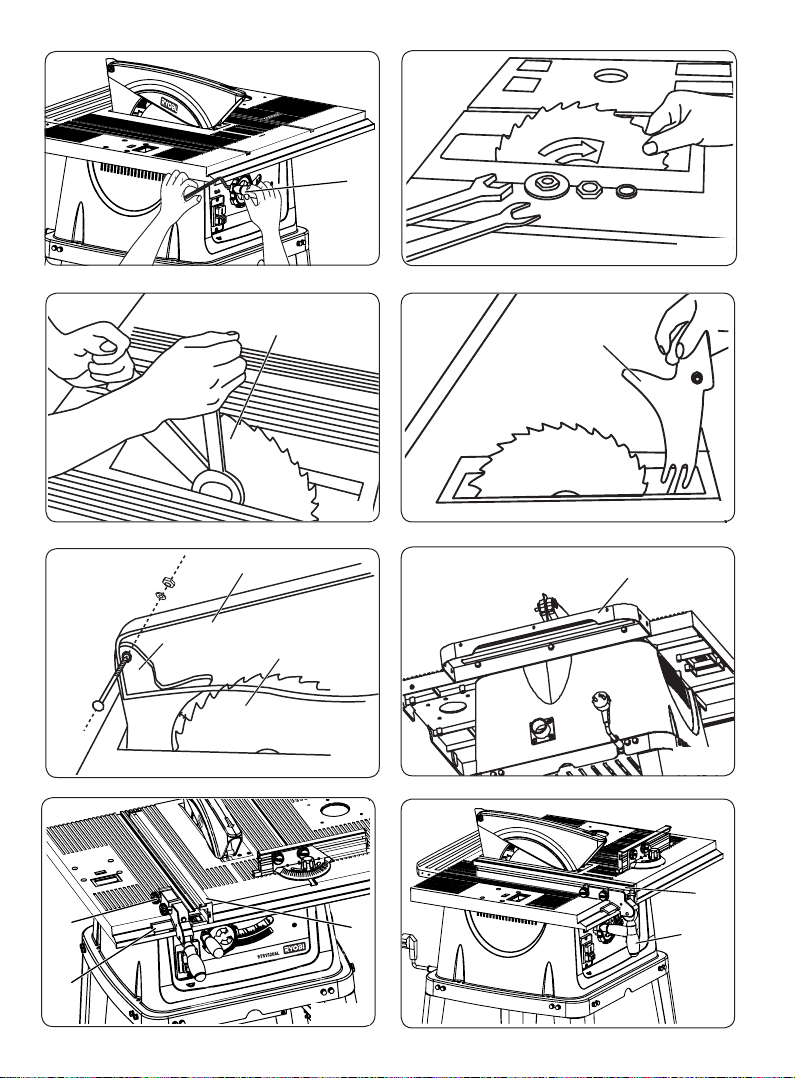
MOUNT THE RIVING KNIFE (FIG. 4&5)
If in place, remove the table insert(17)by
removing the four phillips flat head screws.
Insert the riving knife(20), so that the long
slots in the riving knife fit around the hexagon
socket head end screws (Fig.4). Adjust the
riving knife(20) so that the clearance between
riving knife(20) and blade(15) is between 2
to 5mm (Fig.5); then tighten the hexagon
socket headed screws. Check to ensure the
riving knife(20) and saw blade(15) is in line.
Then check again that the blade is securely
tightened and remount the table insert.
Then mount the blade guard(7). (Fig. 5)
MOUNT THE RIP FENCE (FIG. 6&7)
Loosen the rip fence lock knobs(5) on the
sliding block(19), then slide the fence(6)
onto the bolt heads and tighten the rip
fence lock knobs(5) (Fig. 6)
To lock the rip fence(6), slide the rip fence
assembly until the indicator is pointing to
the desired setting. Then press rip fence
lock handle (3) downwards (Fig.7), to
lock the fence into position.
Ensure the fence is locked before
operating the saw.
Remove the table insert(17) by removing the
four Philips flat head screws.
Turn the elevating handle(13) (Fig.1) in the
counterclockwise direction to raise the
blade shaft to its highest position (fig.3).
Remove the blade fixing nut by turning in
a counterclockwise direction, then pull the
outer flange from the shaft and the outer
arbor. Mount the blade(15) (be sure that the
teeth are facing downwards at the front side
of the saw). Replace the outer flange and re-
fit the blade fixing bolt. Check that the blade
is correctly seated before tightening the bolt.
Check again that the blade(15) is securely
tightened and re-fit or adjust riving knife as
necessary, before re-mounting the table
insert(17).
WARNING!
Replace table insert when worn.
MOUNT THE BLADE (FIG. 1, 2&3)
tightening the set screw in the handle (fig.1).
ASSEMBLE EXTENSION TABLE (FIG. 5a)
Align the 3 holes of rear extension table
(24) with 3 M6 x12, flat washer, spring
washer and secure the rear extension
table(24) to the main table.
Page 11

ADJUSTMENT OF SAW BLADE (FIG. 8, 9&10)
WARNING:
• Do not use saw blades which are
damaged or deformed.
• Use only saw blades recommended by
the manufacturer.
• Take care that the selection of the saw
blade depends on the material to be cut.
The Blade(15) has been adjusted at the
f
actory, use a square to check that the blade
is at a 90o angle to the table (Fig.8)
Page 5
If adjustment is needed turn the tilting lock
nut (while holding the adjustment in position)
to fix the adjustment.
Then loosen the indicator fixing screw, set the
indicator of the scale(12) on the " 0
o
" marked
then tighten the fixing screw(Fig.9)
After the 90
o
setting of the blade has been
adjusted turn the tilting handle to the 45o
(Fig.10) side and adjust the 45
o
angle.
Turn the adjustment nut so that the blade is
on the 45
o
position and then tighten the lock
nut.
OPERATION ON/OFF MAGNETIC SWITCH (FIG. 11)
The magnetic switch (2) is a safety feature of
the machine. Should the supply be interrupted
the switch will automatically default to the
“OFF” position preventing a dangerous
unexpected startup of the machine when the
supply is restored.
Press the ‘ON’ button to start the machine.
Press the ‘OFF’ button to stop the machine.
WARNING: Before turning the machine
ON, make sure the blade guard is correctly
installed and operating properly.
OVERLOAD RESET BUTTON (FIG. 11)
Your table saw features an overload reset
button(14). In the event that your saw turns off
during operation, turn the saw off and allow
the motor to cool down for approximately
3 minutes. Push the reset button(14) and
attempt to turn the saw on again. If the saw
does not turn on, turn the switch off and
check all cords for proper connection and
retry. If it turns on and then cuts off while you
are working, you may be trying to feed the
workpiece too quickly or may be operating
with a dull blade or may be trying to operate
on an insufficient voltage.
I
O
Live Indicator (FIG. 11)
When the machine is connected with the
power supply, the live indicator (4) will glow.
If not, please check if the power plug is well
connected.
ELEVATING HANDLE (FIG. 12)
Elevating handle (13) is used to raise and
lower the blade. Turn it clockwise to lower and
counterclockwise to raise it.
Please note - this handle will move sideways
as the tilt or bevel is adjusted.
Page 12

CROSSCUTTING (FIG. 14)
Page 6
Crosscutting is cutting wood across the grain
at 90° or square with both the edge and the
flat side of the wood. This is done with the
mitre gauge(9) set at “0”. Before using it,
make sure it is locked(10). The mitre gauge
(9) can be used on either of the grooves in the
table. To change groove,slide the mitre gauge
assembly out of its groove and into the other
groove .Adjust it to the desired setting before
operating.
MITRE CROSSCUTTING (FIG. 15)
Mitre crosscutting is cutting the wood at
an angle other than 0° with the edge of the
wood on the mitre gauge(9). Follow the same
procedures as you would for crosscutting.
Adjust the Mitre gauge (9) to the desired
angle.
BEVEL CUTTING (FIG. 16)
Bevel crosscutting is similar to crosscutting
except that the wood is cut at an angle other
than the 90° with the flat side of the wood or
table. Adjust the blade to the desired angle.
COMPOUND MITRE CUTTING (FIG. 17)
Compound mitre cutting is a combination of
mitre cutting and bevel crosscutting. The cut
is made at an angle other than 90° to both
the edge and the flat side of the wood. Adjust
the mitre gauge(9) and the blade(15) to the
desired angle and ensure the mitre gauge(9)
is locked by using the mitre gauge lock(10).
REPETITIVE CUTTING (FIG. 18&19)
Repetitive cutting is cutting a number of
pieces the same length without having to
mark each piece. Do not feed the workpiece
with your hand (Fig.18). Guide it and make
sure that it does not bind or pinch the saw
blade (Fig.19). Never use the rip fence (6) as
a length stop because the cutoff piece could
bind between the fence (6) and the blade (15)
causing a kickback.
USING RIP FENCE (FIG. 19&20)
The rip fence (6) is used for all ripping
operations. Never rip freehand without the
fence in place and securely locked.
Ripping is cutting a piece of wood with the
grain or length wise(Fig.19). This is done
using the rip fence(6). Position the fence by to
the desired width of the rip and lock it in place.
Before starting to rip, be sure the rip fence is
parallel to the saw blade (15) and the riving
knife is properly aligned with the saw blade.
When ripping long boards or large panels,
always use a work support. Hold the piece
against the fence (6) and feed it through the
blade (15) with a smooth, steady pressure.
Always use the push stick (16) to feed the
workpiece until it is clear of the table. (Fig. 20)
MITRE GAUGE (FIG. 14)
The head is locked in the desired position for
crosscutting or mitre cutting by tightening the
mitre gauge lock(10). Always lock it securely
when in use by turning the mitre gauge
lock(10).
TILTING HANDLE (FIG. 13)
The tilting handle(23) is used to tilt the blade
for bevel cutting. Turn it clockwise to tilt toward
the left and counterclockwise to tilt toward the
right.
Page 13

BEVEL RIPPING (FIG. 20)
When bevel ripping material of 6” (150mm) or
narrower, use only the push stick(16) to feed
Page 7
DUST COLLECTION (FIG. 21)
Fasten your dust collector to the back side of
the table to the dust port(22) (Fig. 21).
The dust efficiency measurement is 45%.
MOUNT THE TABLE SAW TO THE STAND (FIG. 22&23)
Do not make any adjustment while the motor
is in motion. Always make sure the machines
plug has been removed from the mains power
source before changing brushes, lubricating
or when doing any works or maintenance
on the machine. After each use, check your
machine for damage or broken parts and
keep it in top working condition by repairing
or replacing parts immediately. Clean out
accumulated dust. To assure safety and
reliability, all repairs with the exception of
externally accessible brushes should be
performed by an AUTHORISED SERVICE
CENTRE. Faults in the machine, including
guards or saw blades, should be reported as
soon as they are discovered.
MAINTENANCE
Turn stand(21) u pr ight as shown.
Insert the cr os s head screws, spring
washers and flat washer t o assembl e the
fou r legs and cross braces first. (Fig. 23)
leave all bolts f in ger tig ht - do not f ul ly
tighten until as se mbly is co mp le te.
Remove the lower extension table brace
bolts Ca re fully place table saw on t op of
stand. Align holes i n t he tabl e saw ba se
with holes in st an d (F ig. 2 3) .
Fully tighte n al l bolts to the st an d before
operation.
WARNING!
The stand consists of 4 holes for mounting
to the ground. Always ensure your table
saw with stand is securely mounted to
the ground. If however, you have decided
not to mount your table saw onto the
stand, please refer to the 4 holes on
the table saw and mount the unit to the
workbench. Always ensure the table saw
is mounted securely either to the stand or
the workbench. Failure to do so, will cause
serious personal injury.
the workpiece past the saw blade.
WARNING!
The dust from some types of wood can
be harmful.
For instance, beech and oak dusts are
especially detrimental to health and therefore
may be worked only with dust collector.
MOUNT THE JIGSAW MOUNTING PLATE TO THE TABLE SAW (FIG. 24)
For details, p le ase re fer t o the Manual of
HBT250/139 Jigsaw Mounting P la te.
MOUNT THE ROUTER MOUNTING PLATE TO THE TABLE SAW (FIG 25)
For details, p le ase re fer t o the Manual of
HBT250/NCF Route r Mo un ting Kit.
Page 14

RYOBI TECHNOLOGIES AUSTRALIA PTY. LTD.
GUARANTEE
RYOBI TECHNOLOGIES AUSTRALIA PTY. LTD.
A.B.N. 98 002 277 509
Contact during normal business hours.
RYOBI NEW ZEALAND PTY. LTD.
AUCKLAND: 27 Clemow Drive, Mt Wellington, N.Z.
Contact during normal business hours.
Subject to the guarantee condition below, this Ryobi tool
(hereinafter called “the product”) is guaranteed by Ryobi
(hereinafter called “the Company”) to be free from
defects in material or workmanship for a period of 24
months from the date of original purchase covering
both parts and labour. Under the terms of this
guarantee, the repair or replacement of any part shall
be the opinion of the Company or its authorised agent.
Should service become necessary during the warranty
period, the owner should contact the RYOBI HELPLINE
1300 361 505 or contact the retailer from whom the
product was purchased.
In order to obtain guarantee service, the owner must
present the sales docket and Guarantee Certificate
to confirm date of purchase. This product is sold by the
dealer or agent as principal and the dealer has no
authority from the Company to give any additional
guarantee on the Company’s behalf except as herein
contained or herein referred to.
Guarantee Conditions
This guarantee only applies provided that the Product
has been used in accordance with the manufacturer’s
recommendations under normal use and reasonable
care (in the opinion of the Company) and such
guarantee does not cover damage, malfunction or
failure resulting from misuse, neglect, abuse, or used
for a purpose for which it was not designed or is not
suited and no repairs, alterations or modifications
have been attempted by other than an Authorised
Service Agent. This guarantee will not apply if the tool is
damaged by accident or if repairs arise from normal
wear and tear.
The Company accepts no additional liability pursuant to
this guarantee for the costs of travelling or
transportation of the Product or parts to and from the
service dealer or agent - such costs are not included in
this guarantee.
Certain legislation, including the Trade Practices Act,
1974 (as amended) and other state and territorial laws
give rights to the buyer and impose liability on the seller in
certain circumstances. Nothing herein shall have the effect
of excluding, restricting or modifying any condition,
guarantee, right or liability imposed, to the extent only
that such exclusion, restriction or modification
would render any term herein void.
BRISBANE : All enquiries Tel : 1300 361 505
TOWNSVILLE: All enquiries Tel : 1300 361 505
MELBOURNE: 960 Stud Road, Rowville,Vic. 3178
Tel : (03) 9764 8656
HOBART: All enquiries Tel : 1300 361 505
ADELAIDE: All enquiries Tel : 1300 361 505
PERTH: 33-35 Sorbonne Cres. Canning Vale, W.A. 6155
Address Of Dealer
Present This Form With Your Purchase Docket When Guarantee Service Is Required.
Tel: 1300 361 505 - Fax: 1800 807 993 - www.ryobi.com.au
Tel: (09) 573 0230 - Free Call: 0800 279 624 - Fax: (09) 573 0231 - www.ryobi.co.nz
SYDNEY: Building B, Rosehill Industrial Estate, 3 - 5 Shirley Street, Rosehill N.S.W. 2142
Tel : (08) 9455 7775
This Guarantee Form Should Be Retained By The Customer At All Times
For your record and to assist in establishing date of purchase (necessary for in-guarantee service)
please keep your purchase docket and this form completed with the following particulars.
Date Model No Serial No
 Loading...