

Page 1
RYOBI.
Operator’s Manual
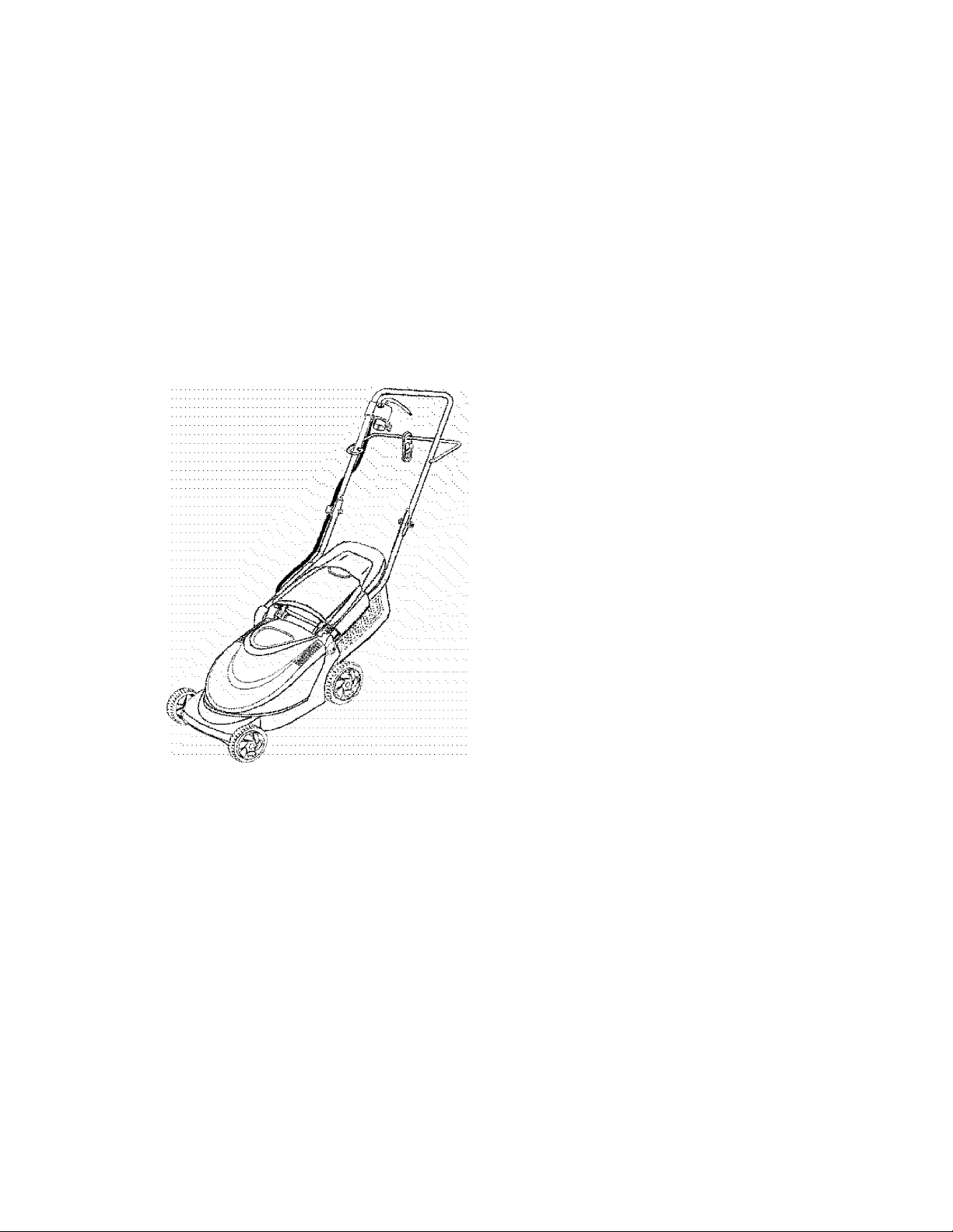
Electric Lawn Mower
13” Rear Bagger
Item Number
Model 136
247.370380
IMPORTANT: READ SAFETY RULES AND INSTRUCTIONS CAREFULLY
This symbol on the products nameplate
means it is listed by
®
UNDERWRITERS LABORATORIES INC.
MTD LLC P.O. BOX 361131 CLEVELAND, OHIO 44136-0019
FORM NO. 769-00620
(12/2002)
Page 2

TABLE OF CONTENTS
Content Page
Important Safe Operation Practices
Slope Gauge...................................................................................................................6
Assembling Your Lawn Mower..
Know Your Lawn Mower.................................................................................................10
Operating Your Lawn Mower..........................................................................................11
Making Adjustments.......................................................................................................12
Maintaining Your Lawn Mower..
Off-Season Storage........................................................................................................14
Troubleshooting
Parts List.........................................................................................................................16
...
.............................................................................................. 15
...............................................................................
............................................................................ 7
............................................................................ 13
3
FINDING MODEL NUMBER
This Operator's Manual is an important part of your new Lawn Mower. It will help you assemble, prepare and
maintain the unit for best performance. Please read and understand what it says.
Before you start assembling your new equipment, please locate the model plate on the
equipment and copy the information from it in the space provided below. The information on the
model plate is very important if you need help from our Customer Support Department or an
authorized dealer.
You can locate the model number by standing behind the unit and looking at the rear of the deck. A sample
model plate is explained below. For future reference, please copy the model number and the serial number of
the equipment in the space below.
MEETS CPSC BLADE SAFETY REQUIREMENTS
.....
Y AND ANSI B71.1-1998 : : : :
Model Number
18A-136-034
24T.370380
RY03I
WWW. RyobiOutdoor. com
Serial Number
MTD LLC
P.O.BOX 361131
CLEVELAND, OK 44138
800-683--i006
Copy the model number here:
Copy the serial number here:
CALLING CUSTOMER SUPPORT
If you have difficulty assembling this product or have any questions regarding the controls, operation or
maintenance of this unit, please call the Customer Support Department.
Call 1- (330) 558-7210 or 1- 800-683-1006 to reach a Customer Support representative. Please have
your unit’s model number and serial number ready when you call. See previous section to locate this
information. You will be asked to enter the serial number in order to process your call.
Page 3
SECTION 1: IMPORTANT SAFE OPERATION PRACTICES
READ ALL INSTRUCTIONS!
WARNING: This symbo! points out important safety instructions, which if not followed, could endanger the per
sonal safety and/or property of yourself and others. Read and follow all instructions in this manual before attempting to
A.
A
A
operate this machine. Failure to comply with these instructions may result in personal injury. When you see this sym
bol—HEED ITS WARNING.
DANGER; This machine was built to be operated according to the rules for safe operation in this manual. As with any
type of power equipment, carelessness or error on the part of the operator can result in serious injury. This machine is
capable of amputating hands and feet and throwing objects. Failure to observe the following safety instructions could
result in serious injury or death.
When using electric lawnmowers, basic safety precautions should always be followed to reduce the risk of fire, electric
shock, and personal injury. These basic precautions include the following;
GENERAL OPERATION
Read, understand, and follow ail instructions on the
machine and in the manual before attempting to
assemble and operate. Keep this manual in a safe place
for future and regular reference and for ordering
replacement parts.
2.
Be familiar with all controls and their proper operation.
Know how to stop the machine and disengage them
quickly.
Never allow children under 14 years old to operate this
3.
machine. Children 14 years old and over should read and
understand the operation instructions and safety rules in
this manual and should be trained and supervised by a
parent.
4.
Never allow adults to operate this machine without
proper instruction.
5.
To help avoid blade contact or a thrown object injury, stay
in the operator zone behind the handles and keep
children and bystanders at least 75 feet from the machine
while it is in operation. Stop motor if anyone enters the
area.
6.
Thoroughly inspect the area where the equipment is to
be used- Remove ail stones, sticks, wire, bones, toys and
other foreign objects, which could be tripped over or
thrown by the blade. Thrown objects can cause serious
personal injury.
Plan your mowing pattern to avoid discharge of material
toward roads, sidewalks, bystanders and the like. Also,
avoid discharging material against a wall or obstruction,
which may cause discharged material to ricochet back
toward the operator.
Always wear proper eye protection while operating or
8.
performing an adjustment or repair to protect your eyes.
Thrown objects which ricochet can cause serious injury
to the eyes.
Always use a face or dust mask if operating in a dusty
environment.
Dress Properly - Do not wear loose clothing or jewelry.
10.
They can be caught in moving parts. Use of rubber
gloves and footwear is recommended when working
outdoors.
11.
Ground Fault Circuit Interrupter (GFCI) protection should
be provided on the circuit(s) oroutlet(s) to be used for the
lawn mower. Receptacles are available having built-in
GFCI protection and may be used for this measure of
safety.
12.
To prevent electric shock use only with a UL listed
extension cord set suitable for outdoor use, such as Type
SW-A, SOW-A, STW-A, STOW-A, SJW-A. SJOW-A.
SJTW-A, or SJTOW-A.
13.
Extension Cord - Make sure your extension cord set is in
good condition, is heavy enough to carry the current your
mower wiii draw, and is polarized (one blade of plug is
wider than the other). A100’ length of 14 AWG cord
should be used. An acceptable substitute is a 50’ length
of 16 AWG cord. If a longer cord is needed, a 150’ length
of 12 AWG cord may be used. A longer length or
undersized cord will cause a drop in line voltage resulting
in a loss of power and overheating.
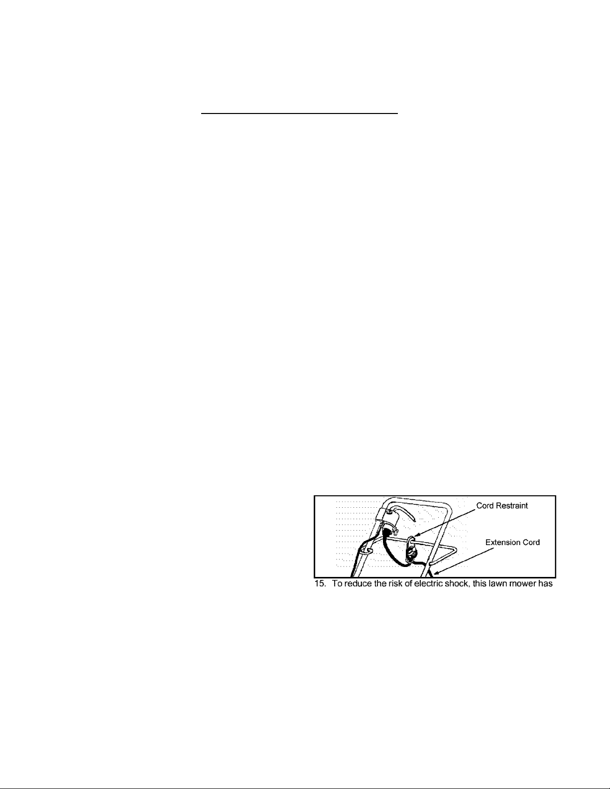
14.
To reduce the likelihood of disconnection of the lawn
mower from the extension cord set, be sure to use the
cord restraint provided as shown in the illustration below
as well as a modern, tightly fitting extension cord;
a polarized plug (one blade is wider than the other) and
will require the use of a polarized extension cord. The
mower plug will only fit into the polarized extension cord
one way. If the plug does not fit fully into the extension
cord, reverse the plug. If the plug still does not fit, obtain a
correct polarized extension cord. A polarized extension
cord will require the use of a polarized wall outlet. This
plug will fit into the polarized outlet only one way. If the
plug does not fit fully into the wall outlet, reverse the plug.
If the plug still does not fit, contact a qualified electrician
to install the proper wall outlet. Do not change the
equipment plug, extension cord receptacle, or extension
cord plug in any way.
Page 4

16. Home circuit This mower should be operated on a 15
AMP circuit. If you experience difficulty in starting with a
standard 15 AMP fuse or circuit breaker, contact your
nearest authorized service facility. Do not use a higher
rated fuse or breaker without consulting your power
company,
17. Do not abuse the cord by pulling the mower by the cord
or yanking it to disconnect it from the receptacle. Keep
cord from heat, oil, and sharp edges.
18. Many injuries occur as a result of the mower being pulled
over the foot during a fall caused by slipping or tripping.
Never operate this machine in bare feet, sandals,
slippery or lightweight (e.g. canvas) shoes. Do not hold
on to the mower if you are falling; release the handle
immediately.
19. Never pull the mower back toward you while you are
walking. If you must back the mower away from a wail or
obstruction first look down and behind to avoid tripping
and then follow these steps:
• Step back from the mower to fully extend your arms.
* Be sure you are well balanced with sure footing.
* Pull the mower back slowly, no more than halfway
toward you.
• Repeat these steps as needed.
20. Do not use lawn mower for any job except that for which it
is intended. Do not force the lawn mower ^ Cut grass at a
rate, for which the mower is designed, which will not
sacrifice the performance or safety of the machine.
21. Do not operate the mower while under the influence of
alcohol or drugs.
22. Stay Alert ~ Do not operate the mower when you are
tired. Watch what you are doing. Use common sense.
23. Do not put hands or feet near rotating parts or under the
cutting deck. Contact with the blade can amputate hands
and feet.
24. Never attempt to make a wheel or cutting height
adjustment while the motor is running.
25. Avoid dangerous environments ~ Never operate the
mower in the rain or in wet or damp grass.
26. Mow only in daylight or in good artificial light. Walk, never
run.
27. Stop the blade when crossing gravel drives, walks or
roads.
28. If the equipment should start to vibrate abnormally, stop
the motor and check immediately for the cause. Vibration
is generally a warning of trouble.
29. Stop the motor and wait until the blade comes to a
complete stop before removing the grass catcher or
unclogging the chute. The cutting blade continues to
rotate for a few seconds after the motor is shut off. Never
place any part of the body in the blade area until you are
sure the blade has stopped rotating.
30. Never operate mower without proper trail shield,
discharge cover, grass catcher, motor/blade control or
other safety protective devices in place and working.
Never operate mower with damaged safety devices.
Failure to do so can result in personal injury.
31. Only use parts and accessories made for this machine by
the manufacturer. Failure to do so can result in personal
injury.
32. If situations occur which are not covered in this manual,
use care and good judgment. Contact your dealer or
telephone 1 - 800-683-1006 for assistance and the
name of your nearest servicing dealer.
Slope Operation
Slopes are a major factor related to slip and fall accidents
which can result in severe injury. Operation on slopes
requires extra caution. If you feel uneasy on a slope, do not
mow it. For your safety, use the slope gauge included as part
of this manual to measure slopes before operating this unit on
a sloped or hilly area. If the slope is greater than 15 degrees,
do not mow it.
Do:
1. Mow across the face of slopes: never up and down.
Exercise extreme caution when changing direction on
slopes.
2. Watch for holes, ruts, rocks, hidden objects, or bumps
which can cause you to slip or trip. Tall grass can hide
obstacles. Remove all objects such as rocks, tree limbs,
etc., which could be tripped over or thrown by the blade.
3. Always be sure of your footing. A slip and fail can cause
serious personal injury. If you feel you are losing your
balance, release the motor/blade control handle
immediately, and the blade will stop rotating within 3
seconds.
Do Not:
1. Do not mow near drop-offs, ditches or embankments,
you could lose your footing or balance.
2. Do not mow slopes greater than 15 degrees as shown on
the slope gauge.
3. Do not mow on wet grass. Unstable footing could cause
slipping.
Children
1. Tragic accidents can occur if the operator Is not alert to
the presence of children. Children are often attracted to
the mower and the mowing activity. They do not
understand the dangers. Never assume that children will
remain where you last saw them.
• Keep children out of the mowing area and under the
watchful care of a responsible adult other than the
operator.
* Be alert and turn mower off if a child enters the area.
• Before and while moving backwards, look behind and
down for small children.
* Use extreme care when approaching blind corners,
doorways, shrubs, trees, or other objects that may
obscure your vision of a child who may run into the
mower.
2. Never allow children under 14 years old to operate a
power mower. Children 14 years old and over should
read and understand the operation instructions and
safety rules in this manual and should be trained and
supervised by a parent.
Page 5
Service
1. When servicing use only identical replacement parts
listed in this manual. “Use of parts which do not meet the
original equipment specifications may lead to improper
performance and compromise safetyl”
2. Before cleaning, repairing, or inspecting, make certain
the blade and all moving parts have stopped. Disconnect
the power cord when not in use and to prevent
unintended starting.
3. Follow instructions for lubricating and changing
accessories.
4. Inspect lawn mower cord and extension cords
periodically and replace immediately, if damaged. Lawn
mower cord should be repaired by an authorized service
facility only.
5. Keep handles dry. clean and free from oil and grease.
6. To reduce a fire hazard, keep the motor free of grass,
leaves and debris build-up.
7. Check the blade and motor mounting bolts at frequent
intervals for proper tightness. Also, visually inspect blade
for damage (e.g., bent, cracked, and worn) Replace
blade with the original equipment manufacturer’s {OEM)
blade only, listed in this manual.
8. Maintain your mower with care - Keep mower blade
sharp and clean for best and safest performance. Mower
blades are sharp and can cut, wrap the blade or wear
gloves and use extra caution when servicing them,
9. Keep all nuts, bolts, and screws tight to be sure the
equipment is in safe working condition.
10. Never tamper with safety devices. Check their proper
operation regularly.
11. After striking a foreign object, stop the motor and
disconnect the power cord. Thoroughly inspect the
mower for any damage. Repair the damage before
operating the mower,
12. Grass catcher components, discharge cover, and trail
shield are subject to wear and damage which could
expose moving parts or allow objects to be thrown. For
safety protection, frequently check components and
replace immediately with original equipment
manufacturer’s (OEM) parts only, listed in this manual.
13. When not in use, store lawn mower indoors in a dry area,
locked-up and/or out of the reach of children.
Double Insulated Lawn Mower
Double insulation is a concept in the safety of electric lawn
mowers, which eliminates the need for the usual three-wire
grounded power cord and grounded power supply system.
Wherever there is electric current in the mower, there are two
complete sets of insulation to protect the user. All exposed
metal parts are isolated from the internal metal motor
components with protecting insulation.
IMPORTANT: Servicing of a lawn mower with double
insulation requires extreme care and knowledge of the
system and should be performed only by a qualified
service technician. For repair service we suggest you
return the lawn mower to your nearest authorized
service dealer. Always use original factory replacement
parts when servicing.
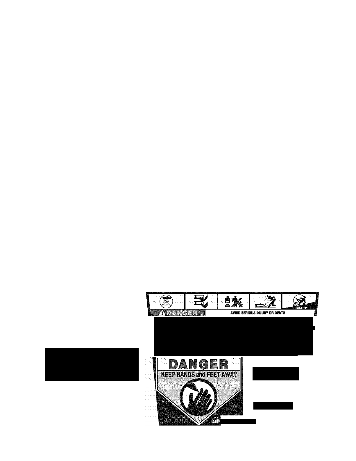
5/^VE JI-IE5E INSTRUCTIONS!
WARNING: YOUR RESPONSIBILITY
• Restrict the use of this power machine to persons who read, understand, and follow the warnings and
instructions in this manual and on the machine.
r TO REDUCE RiSK 0TELECTRi€ SH0CKV:DD NOT EXPOSE UiiiTTO WATER OR OPERATE иИТ OH WET GROUHD- REPLACE-
DAMAQfD CGflD 1ГйЩ0!йТЕ1¥.
DISCONNECT FROM SUPPLY CIRCUIT BEFORE SERViCiNS OR REIfiOViNB BLADE,
* KEEP HANDS AND FEET AWAY FRQ^ ROTATING PARTS- • • • • • • •
- DO NOT iflOVtl WHEN CHILDREN OR OTHERS ARE AROUND,
* REMOVE OBJECTS THAT CAN SE THROWN BY THE BLADE Ш ANY DIRECTION- WEAR SAFETY GLASSES,
TO REDUCE THE RISK OF INJUR
CATCHER ASSEMBLY FREQUE
REPLACE WITH RECOMMENDED
MENT IF THERE ARE SIGNS OF
DETERIORATION.
Y,INSPECT
NTLYAND
REPLACEWEAR OR
« иВЕШВД :САиТ1О^;ОИ:аШРЕ5^0О ЙОТМОЩ SLOPES GREATER THAN tOt MaW ACRPSS NEVERTIP AMD DOWN. :
- TO REDUCE THE RISK 0? JNJUHY, DD NOT OPERATE LAWN MOWER UNLESS CATCHER ASSEMBLY IS ATTACHED.
« WHEN REPAmiNG THIS UNIT USE ONLY IDENTICAL REPLACEMENT PARTS. PARTS MOST BE REASSEMBLED IN
PROPER ORDER TO MAINTAIN DOUBLE INSULATION PROTECTION- REFER TO BEPAIR PARTS SECTION DP YOUR
OWNERS MANUAL OR CONTACT YQUfi AUTHORIZED SERVICE CENTER.
НЕ/Ш№*ЕКАШ)‘$Ш№А1. I^P SAFETY DEtACES (ВШЕ
CONTROL. ТНШНО SHIEU), OISCHAROE COVER. ^
РШ;ЕАМ0ШШ1НС. Й^0М4АЁЕ0,Ш*Ц1С£1№Ш:^ТЕ1У.
WHILE MDVING BACKWARDS. Г
DOUBLE 1MSULATED
ACQHLY
£2М045 АШГ55ИЯ
S30S46
PLACE fiODEL PLATE HERE
: (вШЕ Я
Ш.)№ В
ШЕ1У. й
----
IN eUNGAHY
Page 6
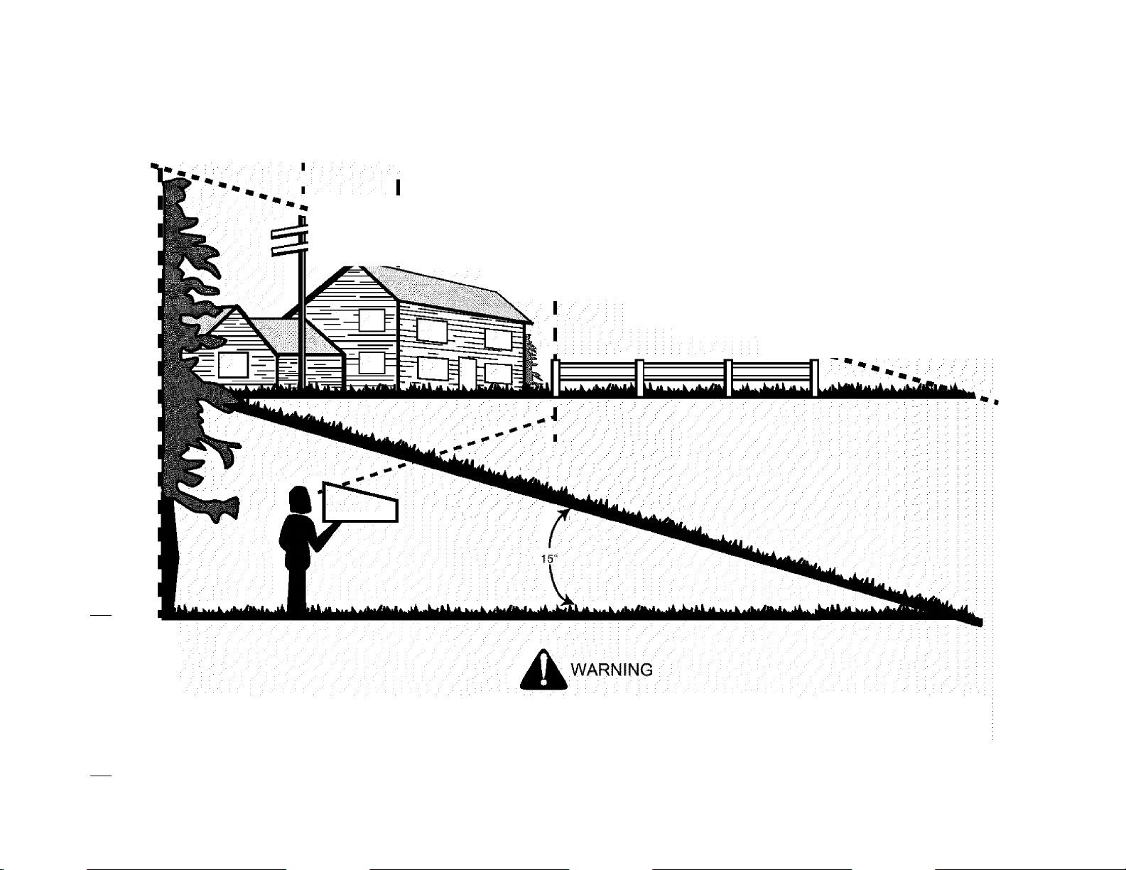
USE THIS PAGE AS A GUIDE TO DETERMINE SLOPES WHERE YOU MAY NOT OPERATE SAFELY.
<D
o
£
c
JO
3
o
o
E
0>
Q.
o
o
o
Q
>,
<0
M
s
<£>
Q.
O
o
c
>,
£
O
<D
<D
x:
SIGHT AND HOLD THIS LEVEL WITH A VERTICAL TREE
—— A POWER POLE
A CORNER OF A BUILDING
----------
i/% Bp
«i
OR A FENCE POST
CS
<
C5
111
O.
00
• •
CVJ
111
CO
<D
Q.
O
<0
0)
.£
£
0
01
“5
*:3
O)
£0
</>
<0
<D ®
U> Q.
iO O
Dl {/)
« x:
x: o
3
<D tf)
05 C
Z) O
Do not mow on inclines with a slope in excess of 15 degrees {a rise of approximately 2-1/2 feet every 10 feet). A riding mower
could overturn and cause serious injury. If operating a walk-behind mower on such a slope, it is extremely difficult to maintain
your footing and you could slip, resulting in serious injury.^ ^ \ : ■
Operate RIDING mowers up and down slopes, never across (he face of slopes.
Operate WALK-BEHIND mowers across the face of slopes, never up and down slopes.
Page 7
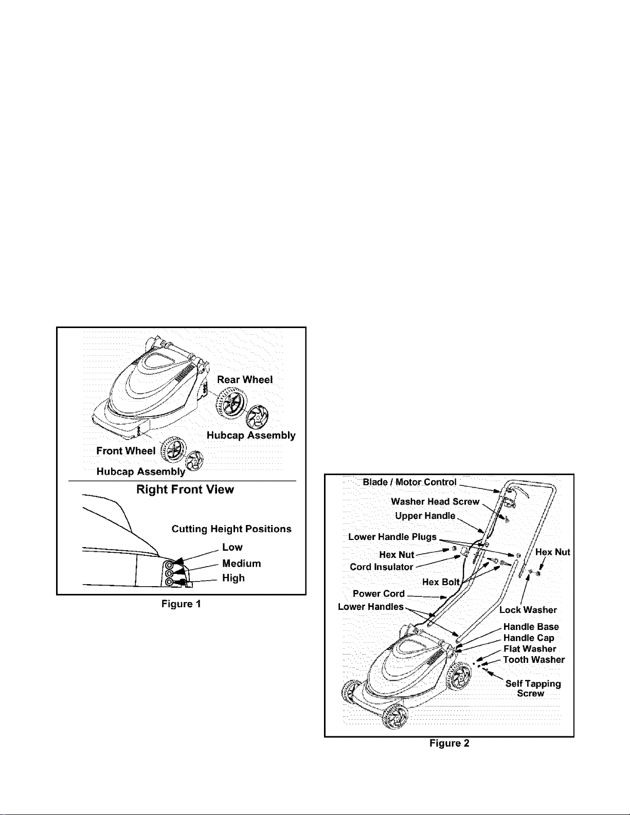
SECTION 3: ASSEMBLING YOUR LAWN MOWER
Loose Parts in Carton
Grass Catcher Assembly.
Owner’s Manual {not shown).
Hardware Pack.
Upper and Lower Handle w/ Guide Rod.
Wheel Assemblies (4)
Tools Required
• Phillips head screwdriver.
• Adjustable wrench, a wrench set or socket set.
Attaching Wheels
The wheeis for your mower will not require tools to
install. Notice that there are two large wheel assemblies
and two smaller wheel assemblies. The large wheels fit
on the rear and the small wheels are for the front of the
mower. To install the wheels:
• Repeat this step for all wheels, being certain that all
four wheels are in the same height position for an
even cut. Refer to Figure 1 for cutting height
positions.
• Also, be certain the smaller front wheels and the
larger rear wheels are mounted correctly to the
front and rear of the mower as shown in Figure 1.
Assembling Handle
Installing ttie Lower Handles
• Insert long end of the lower handle into the handle
base. Make certain the small hole in the end of the
handle is lined up with the hole in handle base.
• Using one of the two longer seif tapping screws
from the hardware pack, insert the screw through
the tooth washer, flat washer, and the handle cap
as shown in Figure 2.
• Align the handle cap so it rests flush against the
handle base, and tighten the screw into the lower
handle using a phillips screwdriver.
• Repeat this step for the remaining lower handle.
• Once both lower handles are installed, insert the
lower handle plugs into the upper ends of the lower
handies as shown in Figure 2.
Installing die Upper Handle
• standing behind the lawnmower with the upper
handle, make certain the two holes that will hold the
blade / motor control are on the right hand side.
See Figure 2 for proper alignment of upper handle.
• Rest the mower on its side or place supporting
blocks under one side of the mower.
• Refer to Figure 1 and insert the hubcap assembly
through the wheel and thread the complete
assembly into the desired height adjustment
position by hand.
NOTE: It is recommended to use the highest cutting
position initially to avoid scalping of the grass.
• By putting fingers into the grooves In the hubcap
assembly, tighten firmly.
Page 8
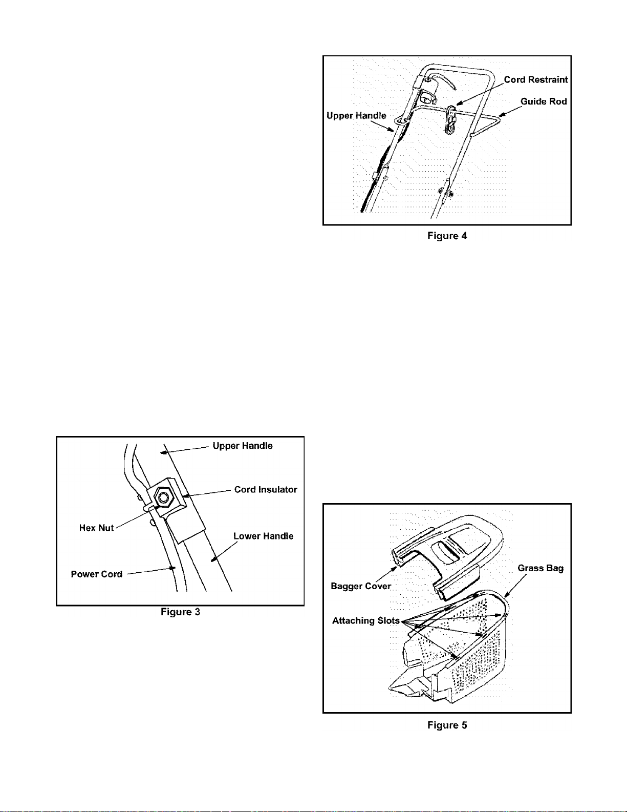
• Align the holes in the lower handle with those of the
upper handle and insert the hex bolts through both
holes.
• On the left side, install the lock washer and hex nut
and tighten finger tight.
• On the right side, insert the hex nut into the hex
hole in the cord insulator and thread onto the hex
bolt on the right side. Make certain that the curved
portion of the cord insulator is resting flush against
the upper handle.
• Tighten the hardware firmly using an adjustable
wrench or suitable tightening tool.
• Refer to Figure 2 for proper alignment of hardware
and handles.
Attaching ttie Blade / Motor Control to the Upper
Handle
• Holding the blade / motor control, which is attached
to the mower, route the power cord as it is shown in
Figure 2 along the right side of the handle.
• Mount the blade / motor control to the upper handle
by inserting its two pedestals into the two holes in
the upper handle. Refer to Figure 2 for correct
positioning on the upper handle.
• Close the rear cover on the blade / motor control
and using the small washer head screws included
in the hardware kit, screw them into the holes in the
rear cover with a phillips screwdriver, thus securing
the blade / motor control to the upper handle.
• Route the power cord through the cord insulator on
the right handle as shown in Figure 3.
Slide the cord restraint onto the guide rod as shown
in Figure 4.
Standing behind the unit, working on the left portion
of the upper handle, insert the Z-end of the guide
rod into the hole on the outer part of the upper
handle.
With the left part of the guide rod inserted in the
upper handle, bring the other end of the guide rod
around the outside of the upper handle on the right
side, and insert the end into the hole on the inner
portion of the upper handle. Refer to Figure 4 for
proper mounting position.
Assembling Grass Catcher
WARNING: Never operate the mower without
A
the proper trail shield, discharge cover, grass
catcher, blade/motor control or other safety
protective devices in place and working. Never
operate the mower with damaged safety devices.
Failure to do so can result in personal injury.
Installing Guide Rod and Cord Restraint
The guide rod and cord restraint need to be installed on
the upper handle of the lawn mower. To install, see
Figure 4 and continue;
Page 9
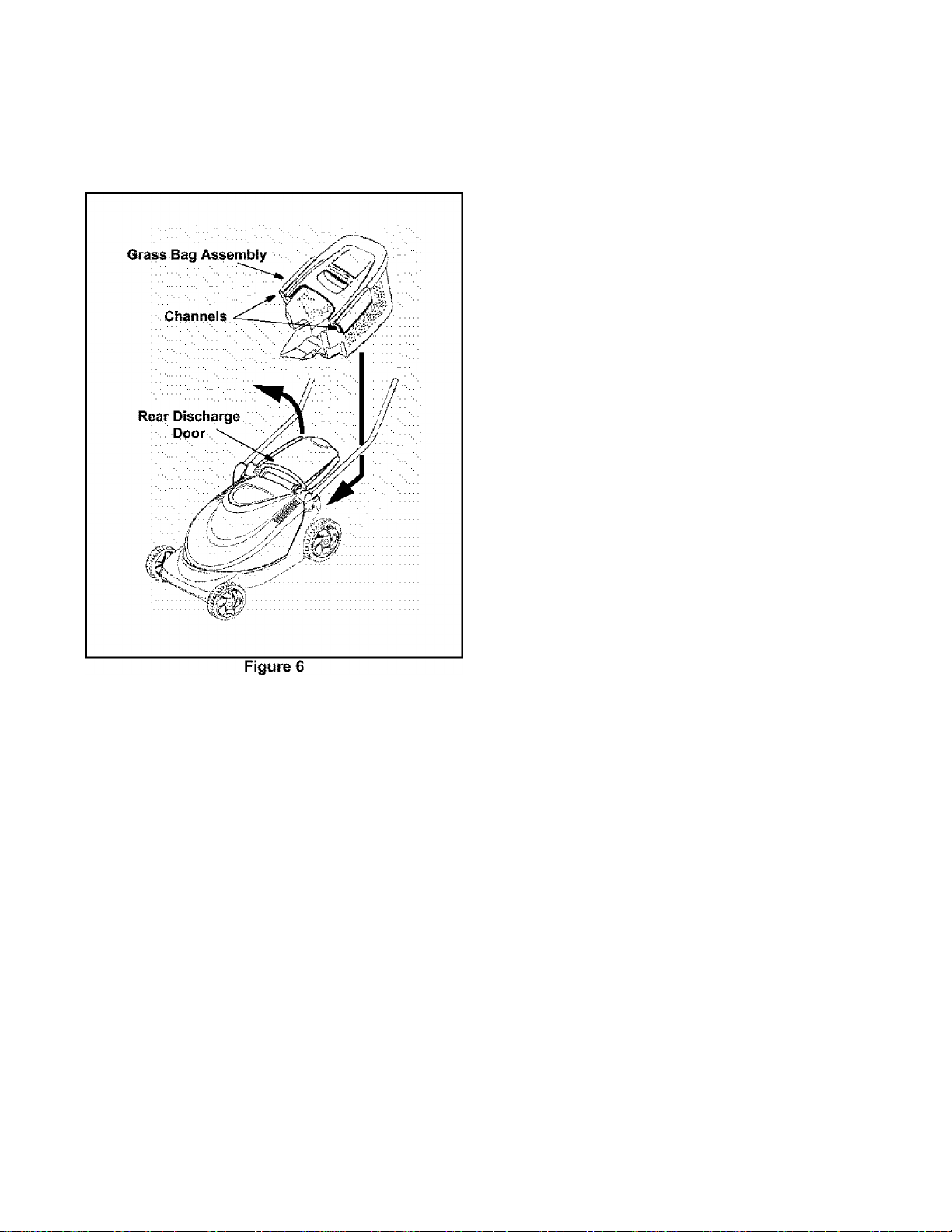
Insert the six clips on the underside of the bagger
cover into the corresponding attaching slots in the
grass bag.
Press firmly in the on the top of the bagger cover in
the area of the attaching slots to ensure that the
clips are locked into place.
Attaching The Grass Catcher
• Lift the rear discharge door on the back of the
mower. Refer to Figure 6.
• Place the channels of the grass bag assembly over
the lower portion of the lower handle as shown in
Figure 6.
• Slide the assembly towards the mower until it rests
against the body of the mower.
• Release the rear discharge door.
To remove the grass catcher, lift the rear discharge
door on the mower. Lift the grass catcher up and off of
the lower handles. Release the rear discharge door.
WARNING: Do not operate this mower with the
A
rear discharge door open, unless the complete
grass catcher is properiy mounted on the mower.
Page 10
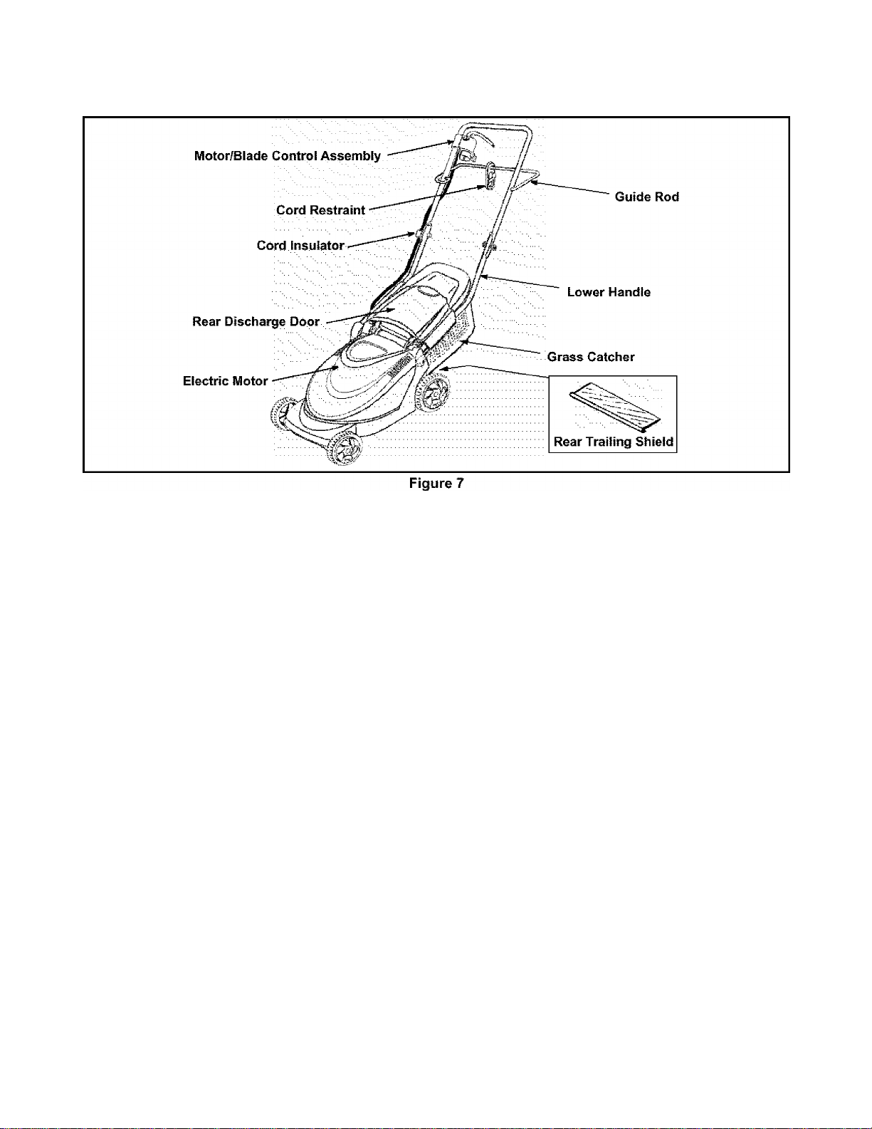
SECTION 4: KNOW YOUR LAWN MOWER
Read this operator’s manual and safety rules before
operating your lawn mower. Compare the illustration in
Figure 7 with your lawn mower to familiarize yourself
with the location of various parts and controls. Save this
manual for future reference.
WARNING: The operation of any lawn mower
can result in foreign objects being thrown into the
A
eyes, which can damage eyes severely. Always
wear safety glasses while operating the mower, or
while performing any adjustments or repairs.
Motor/Blade Control Assembly
The motor/biade control is located on the upper handle
of the mower. Refer to Figure 7. The motor/biade
control handle engages and disengages the motor and
blade.
WARNING: The motor / blade control
assembly is a safety device. Never attempt to
A
bypass its operations.
Rear Trailing Shieid
The rear trailing shield, attached between the rear
wheels of your mower, is provided to minimize the
possibility of objects being thrown at the operator from
the rear of the mower.
Circuit Breaker
The mower is equipped with a circuit breaker, located
on the motor/biade control. Refer to Figure 7. This
circuit breaker may trip when too much strain is placed
on the mower. See Making Adjustments Section.
Guide Rod and Cord Restraint
The cord restraint is located on the back of the upper
handle attached to the guide rod. When used properly,
the cord restraint helps to protect the motor/biade
control assembly and also the extension cord powering
the unit.
Grass Catcher
The grass catcher assembly is designed to catch the
grass clippings that are cut from your lawn. Never mow
without the grass catcher in place on the machine.
Electric Motor
The electric motor is attached to the cutting blade.
When engaged, the electric motor turns the cutting
blade and works to cut grass.
10
Page 11
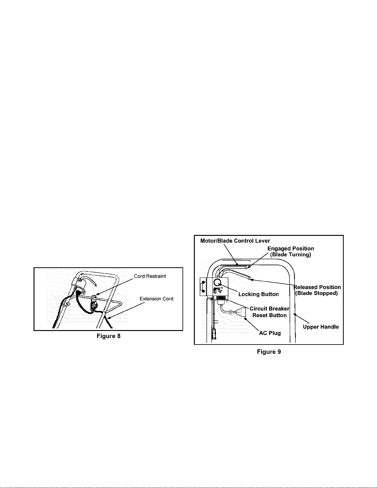
SECTION 5: OPERATING YOUR LAWN MOWER
Cord Connection
Extension Cord Selection
Listed below are the lengths of extension cord and
corresponding acceptable cord ratings.
• 50’Cord —use 16AWG
• 100’Cord — use14AWG
• 150’Cord —use 12AWG
In all cases, the extension cord should be a UL listed
cord set suitable for outdoor use.
IMPORTANT: Using any other length or rating of cord
will diminish the performance and possibly the life of the
electric motor, and may also cause breakers to trip or
fuses to blow in your home’s fusebox.
Cord Restraint
• Attach the extension cord (not provided with unit) to
the cord restraint as follows.
• Form a small loop in the extension cord. Allow
enough excess cord to make the connection to the
motor/blade control (approximately 7 inches).
• Slip the loop through the slot on the bottom of the
cord restraint, and up over the tab, to prevent
disconnection from the motor/biade control during
operation.
• Keep the cord restraint as close to the motor/blade
control as possible. See Figure 7.
Connecting to the Eiectric Power Source
WARNING: This mower should be operated
on a 15 AMP circuit. If you experience difficulty in
A
starting with a standard 15 AMP fuse or circuit
breaker, contact your nearest authorized service
facility. Do not use a higher rated fuse or breaker
without consulting your power company.
Plug the extension cord into any convenient 110-120
volt 60 cycle A.C. outlet or receptacle for your source of
power. This outlet may be located either out-of-doors or
indoors. To avoid blowing fuses, pick an outlet that is
not overioaded. Your mower will operate satisfactorily
on a circuit that is fused for 15 amperes. Do not use
oversize fuses without consulting an electrician. If an
inside receptacle is used, the extension cord can be
taken out either through the doorway or a window.
Starting the Motor and Blade
NOTE: For best results, raise the wheels to the highest
cutting position until it is determined which height is
best for your lawn. See Cutting Height Adjustment in
the Making Adjustments section.
Connecting to the Motor/Biade Controi Assembiy
Connect the plug on the extension cord fully onto the
plug on the motor/blade control. The mower is
equipped with a polarized AC power plug (one blade of
the plug is wider than the other), which will fit into the
plug on the extension cord only one way. If unable to
make a full connection, try reversing the plug on the
extension cord. Should the plugs still fail to fit, contact
your service dealer for assistance. Do not defeat the
safety purpose of the polarized plug.
To engage the motor and blade, first be certain to follow
the previous steps for connecting a suitable extension
cord, then referring to Figure 9:
• Stand behind the unit and depress the locking
button.
• While holding the locking button down, pull the
motor / blade control lever and hold it against the
upper handle.
• Release the locking button.
11
Page 12
stopping the Motor and Blade
WARNING: The blade continues to rotate for a
A
To stop the motor and blade from spinning:
• Release the motor/blade control lever from its
few seconds after the motor is shut off. If the motor
does not come to a stop when the motor/blade
control handle is released^ contact an authorized
service dealer.
position against the upper handle and the blade
and motor will quickly come to a stop.
NOTE: A high pitched noise may occur as the electric
motor deceierates and some sparking may occur also
at the same time. This is normal behavior when the
motor and blade is disengaged.
Mowing Your Lawn
NOTE: A sharp blade will greatly increase the
performance of the lawn mower, especially in
conditions of higher grass. Be sure to check the blade
and sharpen it at least once a year as outlined in the
Maintenance section.
• Be sure that lawn is dear of stones, sticks, wires, or
other objects which could damage the lawn mower
or motor. Such objects could be accidentally thrown
by the mower in any direction and cause serious
personal injury to the operator and others.
• To prevent electric shock, do not operate the
mower in damp or wet conditions.
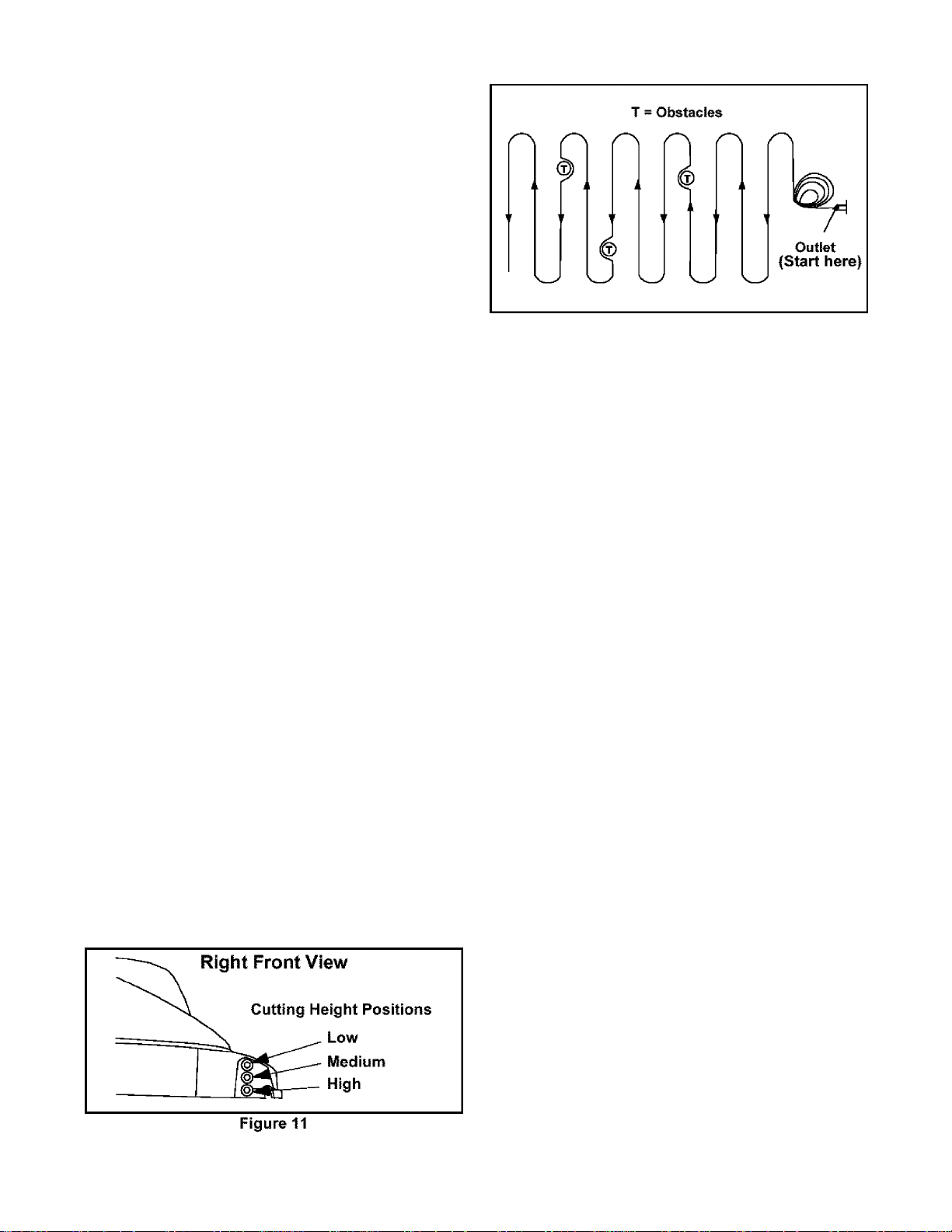
• Always start from the point closest to the powrer
source where the cord is connected. Never mow
around the lawn in circles; travel back and forth
across the lawn, starting from the point closest to
the outlet and then moving away from the outlet so
the cord lies in the cut portion of the lawn, out of the
way. See Figure 10.
Figure 10
Do not allow the extension cord to wrap around
trees, shrubs or other obstacles. When picking up
the extension cord, wind the cord in a series of
equal loops on each side of your hand to prevent
snarling.
When cutting heavy grass, reduce walking speed to
allow more effective cut and proper collection of the
clippings. For a healthy lawn, always cut off onethird or less of the total length of the grass. The
average lawn should be approximately 1-1/2 to 2
inches during the cool season, and over 2 inches
during hot months. For a healthier and better
looking lawn, cut more often and after moderate
growth. The lawn should be cut in the fall season as
long as there is growth.
WARNING: If you strike a foreign object, stop
the motor, and unplug from the power supply
A
circuit. Thoroughly inspect the mower for any
damage, and repair the damage before restarting
and operating the mower. Excessive vibration of
the mower during operation is an indication of
damage. The unit should be promptly inspected
and repaired-
SECTION 6: MAKING ADJUSTMENTS
Cutting Height Adjustment
NOTE: For rough or uneven lawns, move the wheels to
a position which will give a higher cutting height.
WARNING: Always stop the motor and
A
This mower has three cutting height positions as shown
in Figure 11. To adjust the cutting height:
disconnect from the power source before cleaning,
lubricating or performing any repairs or
maintenance on the lawn mower.
12
Page 13
• Remove a wheel assembly and reinstall it in a
different position in order to achieve a higher or
lower position. Refer to the Assembly section also.
• Repeat this procedure for ail wheels, being certain
to mount them all in the same position at each
corner. Failing to do this will produce an uneven
cut.
Resetting the Circuit Breaker
The mower is equipped with a circuit breaker, located
on the motor/biade control assembly as shown in
Figure 9. This circuit breaker may trip when too much
strain is placed on the mower. The circuit breaker may
have been tripped if the mower will not run.
SECTION 7: MAINTENANCE
If this occurs, unplug the mower, wait
approximately five minutes, then depress the reset
button. Refer to Figure 9.
Plug the mower back in, restart the mower, but be
sure to reduce the strain on the mower (i.e., mow at
a higher cutting height, reduce cutting speed, or
take a smaller width of cut).
If the circuit breaker does not reset, or if it trips
repeatedly under normal cutting conditions, unplug
the mower from the extension cord and unplug the
extension cord from the power source. Then check
to make certain your cord is the correct length and
rating as listed in the Operating Your Lawn Mower
section. If the cord is correct and is also not
damaged, take the machine to an authorized
service dealer for repair.
• Using a 15/16” wrench or socket, loosen the blade
bolt and remove the blade.
Installing die Blade
WARNINGi Always stop the motor and
A
disconnect from the power source before cleaning,
lubricating or performing any repairs or
maintenance on the lawn mower.
Cutting Blade Replacement
WARNING: Always protect hands by wearing
A
Removing the Blade
• stop the motor and disconnect the power supply to
• Use a block of wood between the blade and the
heavy gloves and/or wrapping cutting edges with
newspapers or other materials when performing
any blade maintenance. Be certain to disconnect
the power supply.
the mower. Turn the mower on its side.
mower deck to prevent the blade from turning when
removing the bolt.
A WARNING: The blade hardware is not only
used to attach the blade assembly, but is also an
insulated safety device and should never be altered
in any way. If replacement is necessary, use
original equipment parts as shown in the parts list
on page 16.
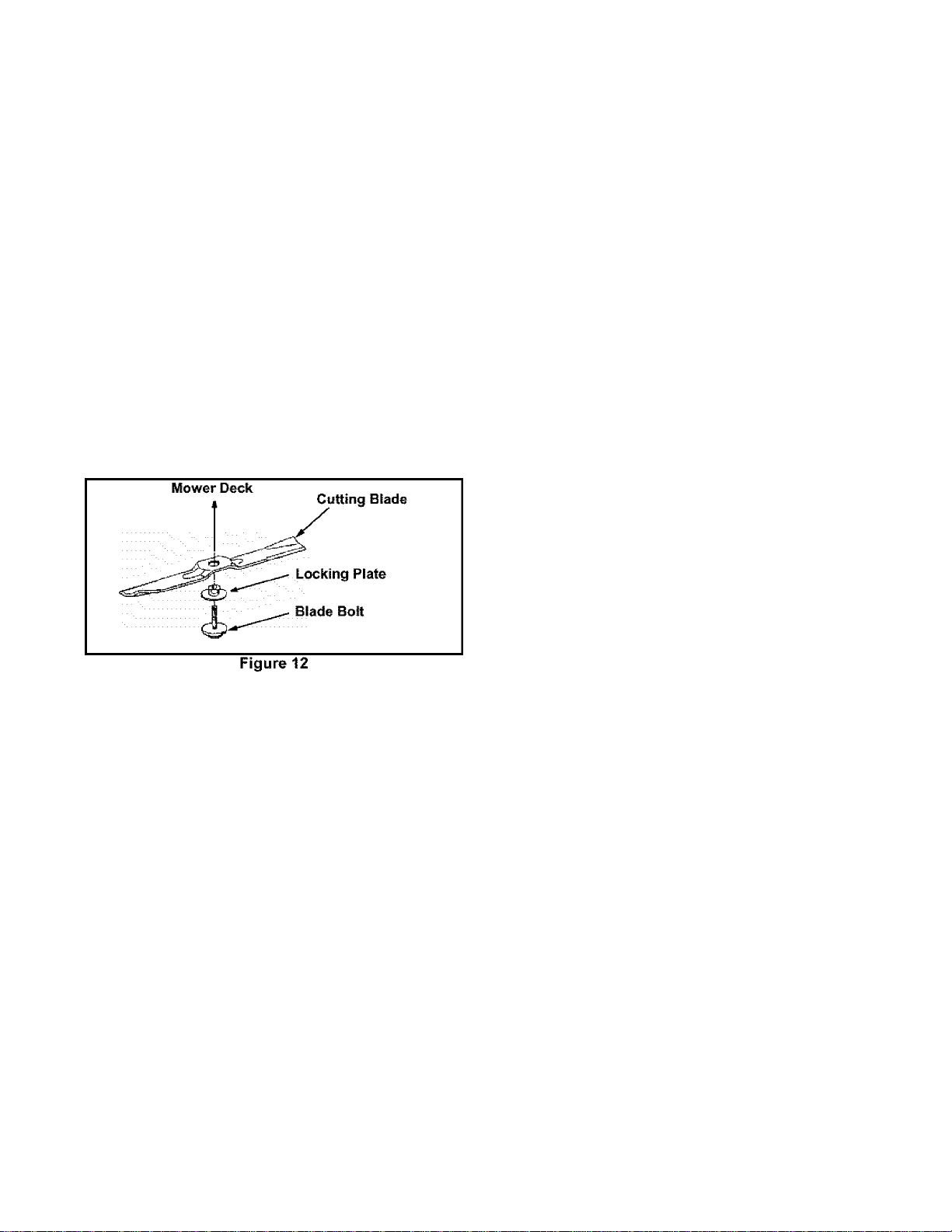
• Place the cutting blade, locking plate, and blade
bolt on the motor shaft and thread the blade bolt in
finger tight. Refer to Figure 12.
NOTE; Make certain to replace the parts in the exact
order in which they were removed. When installing the
cutting blade, be sure it is installed with the curved ends
pointing towards the mower deck and not towards the
ground.
• Torque the blade bolt down using a torque wrench
to assure the bolt is tightened properly. The
recommended torque for the blade bolt is 450-600
in. lbs. To insure safe operation of your unit, all nuts
and bolts must be checked periodically for correct
tightness.
13
Page 14

Sharpening ttie Blade
To sharpen the blade, first remove the blade as outlined
in the previous section. DO NOT attempt to sharpen the
blade while it is attached to the mower. The blade can
be sharpened with a file or on a grinding wheel.
• Reinstall the blade as described earlier in this
section making certain to torque the cutting blade to
specifications.
Mower Deck
1. Insert screw driver through hole
\^
?
2. Balanced blade will be parallel to ground
Screw Driver. Blade
Ground
Figure 13
When sharpening the blade, follow the original
angle of grind as a guide. It is extremely important
that each cutting edge receives an equal amount of
grinding to prevent an unbalanced blade.
Test the blade by balancing it on a round shaft
screwdriver or a blade balancer as shown in Figure
13.
If the blade is not balanced, remove metal from the
heavy side until it balances evenly.
WARNING: An unbalanced blade will
A
cause excessive vibration when rotating at
high speeds. It may also cause damage to the
mower and could break, causing personal
injury.
WARNING: To reduce the risk of electric
A
The underside of mower deck should be cleaned after
each use as grass clippings, leaves, dirt and other
debris will accumulate. This accumulation of grass
clippings, etc., is undesirable as it will promote rust and
corrosion.
• Remove any buildup of grass and leaves on or
• If debris is allowed to build up on the underside of
shock, do not expose the mower to water.
around the motor cover (do not use water). Wipe
the mower clean with a dry cloth occasionally.
the unit, tilt the mower forward or on its side and
scrape it clean with a suitable tool.
Lubrication
At the beginning and end of each mowing season:
• Lubricate the springs on the rear discharge door
with a light oil.
• Remove the wheels and lubricate the surface of the
axle bolt and the inner surface of the wheel with
light oil.
SECTION 8: OFF-SEASON STORAGE
The following steps should be taken to prepare the lawn
mower for storage.
• Make certain the power supply is disconnected.
• Clean mower as instructed in previous section.
• Inspect and replace/sharpen blade if required.
Refer to Cutting Blade section on page 13.
• Lubricate mower following instructions on page 14.
• Store mower in a dry, dean area. Do not store next
to corrosive materials, such as fertilizer and rock
salt.
Wipe extension cord to remove any foreign
substance such as oil or stains. Replace extension
cord if cut or damaged in any way.
Wind cord in a series of equal loops on each side of
your hand to prevent snarling.
Store mower indoors, in a cool, dry place, out of
reach of children. Do not cover lawn mower with a
solid plastic sheet. Any plastic covering traps
moisture around the mower which promote rust and
corrosion.
14
Page 15

SECTION 9: TROUBLE SHOOTING GUIDE
Trouble
Mower not starting.
Circuit breaker on the mower Too much workload on the mower,
tripping.
Mower cutting grass
unevenly.
Hard to push.
Mower vibrating at higher
speed.
Possible Cause(s)
Cord disconnected from the motor/
blade control.
Motor/blade control switch defective. Replace motor/blade control switch.
Extension cord not connected to a
source of power.
Circuit breaker on the mower or in the
house receptacle tripped.
Fuse blown; outlet overloaded.
Lawn rough or uneven.
Cutting height not set properly.
High grass or cutting height too low.
Rear of mower housing and blade
dragging in heavy grass.
Bent motor shaft.
Corrective Action
Reconnect the cord keeping the cord restraint dose
to the motor/blade control.
Connect the extension cord to a 110-120 volt 60
cycle A.C. receptacle.
Reset the circuit breaker following instructions in
the Maintenance section of this manual.
Raise the cutting height, reset the circuit breaker on
the mower, take a smaller width of cut, and walk
slowly.
Connect to an outlet that is fused for 15 amperes.
Reset the circuit breaker and start the mower again.
Move the wheels to a higher cutting height position.
All wheels must be placed in the same cutting
height for the mower to cut evenly.
Raise cutting height.
Raise cutting height.
Stop the motor, disconnect the power source and
inspect for damage. Repair before restarting. If
vibration persists, take it to a service dealer.
Blade is unbalanced.
Cord disconnects frequently. Extension cord is not properly attached
to the cord restraint.
Old, worn, or loose extension cord. Replace extension cord.
Balance the blade by grinding each cutting edge
equally.
Reconnect the extension cord to the cord restraint
on the guide rod.
15
Page 16
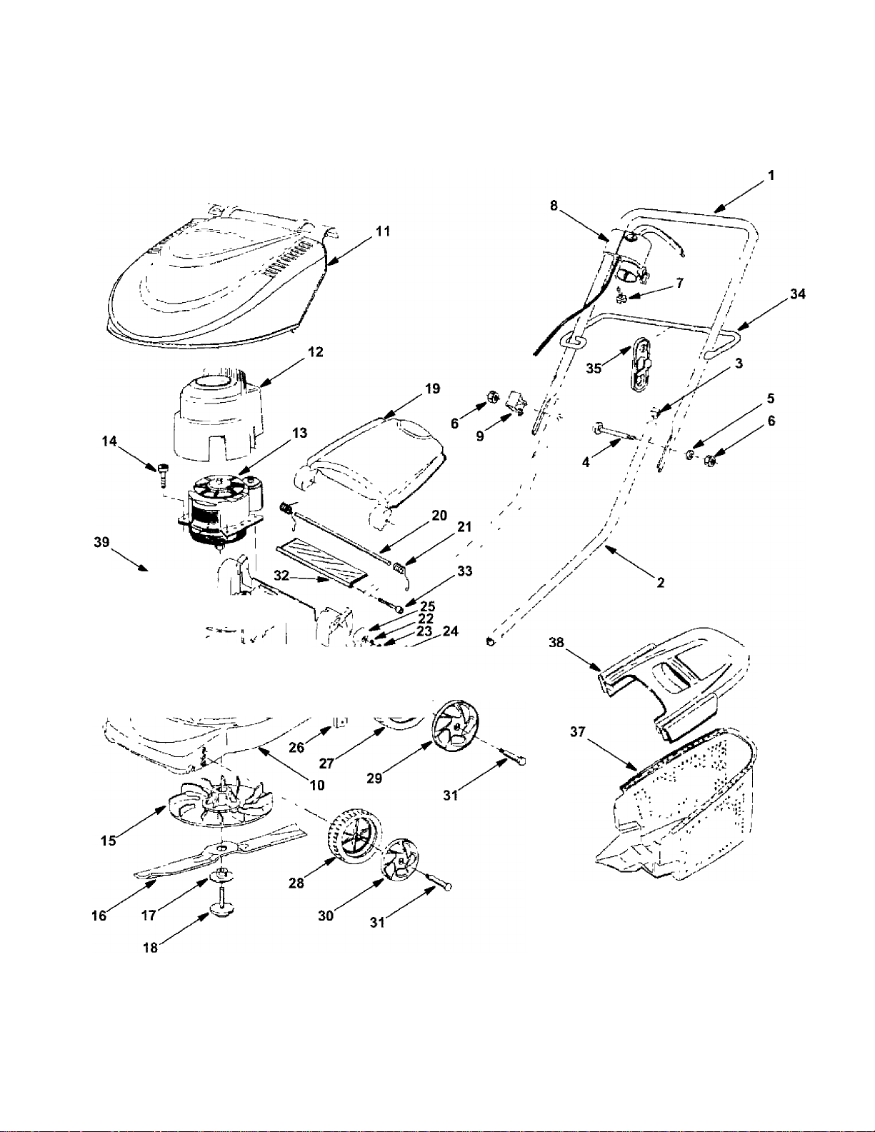
SECTION 10: PARTS LIST
'' ^ 'pM'
16
Page 17
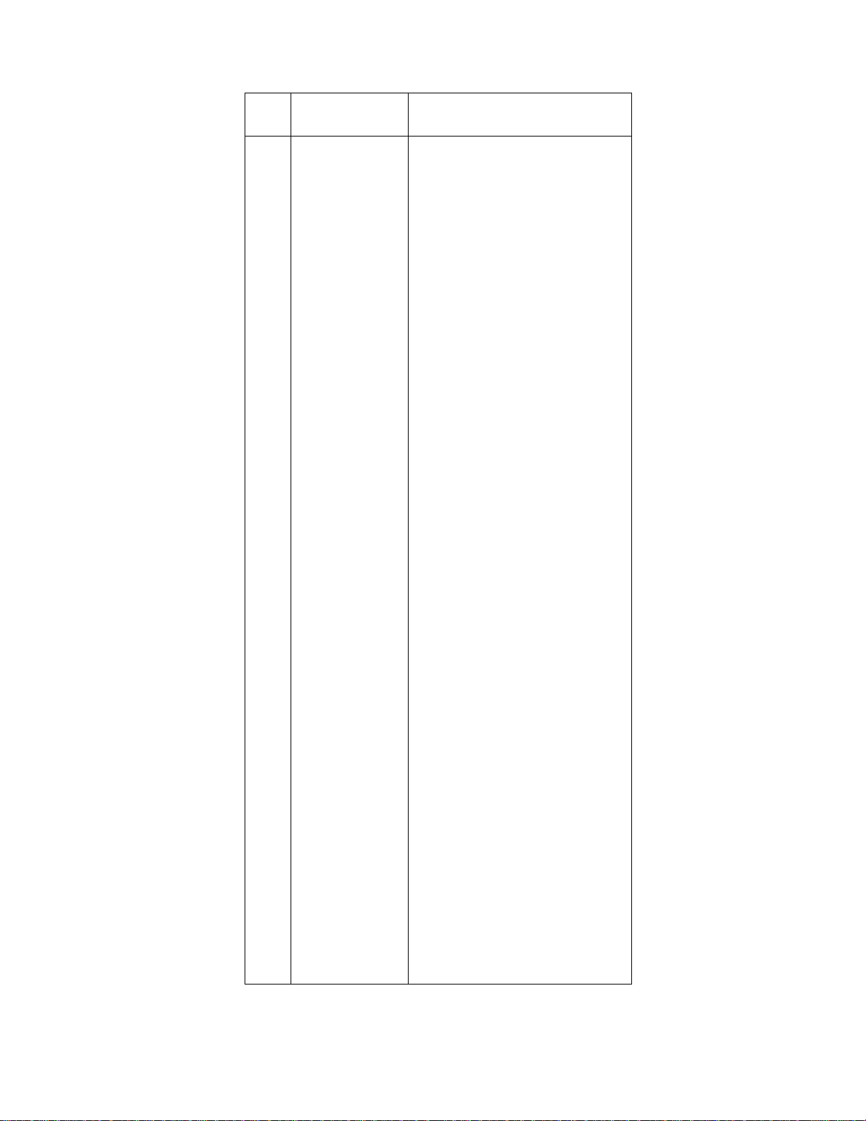
REF.
PART NO.
NO.
1 749-1042A
2 749-1312
720-0369
3
4
710-1718 Handle Bolt
736-0649 Lock Washer
5
6
712-0690
7 710-1757 Screw
725-04075
8
731-2427 Cord insulator
9
10
731-2421-0638
11 731-2088A-0637 Electric Motor Cover
12 731-2224
13 724-0310
14
710-1756
15 631-0148 Blade Hub Assembly
16 742-0804
17
731-1961
624-0077
18
731-1971A-0637
19
20 747-1072
21 732-0912 Spring
22 736-0697 Washer
23 736-0698
24
710-1350
25 731-1805-0638 Cap
26 782-0609
27 734-1884-0637
734-1885-0637
28
720-0343-0637
29
30 720-0342-0637
31 738-1031
32 731-2402 Rear Trailing Shield
33 710-1758
34
747-1010 Guide Rod
726-0368-0637 Cable Clamp
35
37 731-1968-0637
731-2426-0637
38
39 782-9095-0638
40 736-0766
41
728-0286
DESCRIPTION
Upper Handle
Lower Handle
Handle Plug
Hex Nut
Motor / Blade Control Switch
Mower Housing {Incl. Ret# 39-41)
Air Guide Pot
Eiectric Motor
Screw
Cutting Blade
Lock Washer
Blade Bolt
Rear Discharge Door
Rod
Lock Washer
Screw
Holder Plate
Rear Wheel
Front Wheel
Rear Wheel Cap
Front Wheel Cap
Axle Bolt
Screw
Grass Bag
Grass Bag Cover
Protection Plate
Washer
Rivet
17
Page 18

NOTES
Page 19

NOTES
Page 20

MANUFACTURER’S LIMITED WARRANTY FOR:
RYOBI
The limited warranty set forth below Is given by MTD LLC with
respect to new merchandise purchased and used In the
United States, its possessions and territories.
MTD LLC warrants this product against defects for a period of
two (2) years commencing on the date of original purchase
and will, at its option, repair or replace, free of charge, any
part found to be defective in materials or workmanship. This
limited warranty shall only apply if this product has been
operated and maintained in accordance with the Operator’s
Manual furnished with the product, and has not been subject
to misuse, abuse, commercial use, neglect, accident,
improper maintenance, alteration, vandalism, theft, fire,
water, or damage because of other peril or natural disaster.
Damage resulting from the installation or use of any
accessory or attachment not approved by MTD LLC for use
with the product(s) covered by this manual will void your
warranty as to any resulting damage.
Normal wear parts or components thereof are subject to
separate terms as follows: All normal wear parts or
component failures will be covered on the product for a period
of 90 days regardless of cause. After 90 days, but within the
two year period, normal wear part failures will be covered
ONLY IF caused by defects in materials or workmanship of
OTHER component parts. Normal wear parts and
components include, but are not limited to; batteries, belts,
blades, blade adapters, grass bags, rider deck wheels, seats,
snow thrower skid shoes, shave plates, auger spiral rubber,
and tires.
HOW TO OBTAIN SERVICE: Warranty service is available,
WITH PROOF OF PURCHASE, through your local authorized
service dealer. To locate the dealer in your area, check your
Yellow Pages, or contact MTD LLC at P.O. Box 361131,
Cleveland, Ohio 44136-0019, or call 1-800-345-TRIM (8746)
or 1-330-558-7210 or log on to our Web site at
www.ryobioutdoor.com.
This limited warranty does not provide coverage in the
following cases:
a. The engine or component parts thereof. These items
carry a separate manufacturer’s warranty. Refer to
applicable manufacturer’s warranty for terms and
conditions.
b. Log splitter pumps, valves, and cylinders have a sepa
rate one year warranty.
c. Routine maintenance items such as lubricants, filters,
blade sharpening, tune-ups, brake adjustments, clutch
adjustments, deck adjustments, and normal
deterioration of the exterior finish due to use or
exposure.
d. MTD LLC does not extend any warranty for products
sold or exported outside of the United States, its
possessions and territories, except those sold through
MTD LLC’s authorized channels of export distribution.
e. Parts that are not genuine MTD parts are not covered
by this warranty.
f. Service completed by someone other than an
authorized service dealer Is not covered by this
warranty.
g. Transportation charges and service calls are not
covered.
No implied warranty, including any implied warranty of
merchantability of fitness for a particular purpose,
applies after the applicable period of express written
warranty above as to the parts as identified. No other
express warranty, whether written or oral, except as
mentioned above, given by any person or entity,
including a dealer or retailer, with respect to any product,
shall bind MTD LLC. During the period of the warranty,
the exclusive remedy is repair or replacement of the
product as set forth above.
The provisions as set forth in this warranty provide the
sole and exclusive remedy arising from the sale. MTD
LLC shall not be liable for incidental or consequential
loss or damage including, without limitation, expenses
incurred for substitute or replacement lawn care services
or for rental expenses to temporanly replace a warranted
product.
Some states do not allow the exclusion or limitation of
incidental or consequential damages, or limitations on how
long an implied warranty lasts, so the above exclusions or
limitations may not apply to you.
In no event shall recovery of any kind be greater than the
amount of the purchase price of the product sold. Alteration
of safety features of the product shall void this warranty.
You assume the risk and liability for loss, damage, or injury to
you and your property and/or to others and their property
arising out of the misuse or inability to use the product.
This limited warranty shall not extend to anyone other than
the original purchaser or to the person for whom it was
purchased as a gift.
HOW STATE LAW RELATES TO THIS WARRANTY: This
limited warranty gives you specific legal rights, and you may
also have other rights which vary from state to state.
MTD LLC, P.O. BOX 361131 CLEVELAND, OHIO 44136-0019; Phone: 1-800-345-TRIM (8746), 1-330-558-7210
 Loading...