

Page 1

(57291
N197
3/81*(5287(5
2:1(5·6OPERATING0$18$/
DOUBLE
INSULATED
THANK YOU FOR BUYING A RYOBI PLUNGE ROUTER
Your new plunge router has been engineered and manufactured to Ryobi’s high standard for dependability,
ease of operation and operator safety. Properly cared for, it will give you years of rugged, trouble free
performance.
CAUTION: Carefully read through this entire owner’s manual before using your
plunge router.
Pay close attention to the Rules for Safe Operation, Warnings and Cautions.
If you use your plunge router properly and only for what it is intended, you will enjoy years of safe, reliable
service.
Thank you again for buying Ryobi tools.
SAVE THIS MANUAL FOR FUTURE REFERENCE.
Page 2
33
Page 3
)LJǘ )LJ
)LJ )LJ
)LJ
)LJ
Page 4
26
37
Page 5
Page 6

GENERAL SAFETY RULES
SAVE THESE INSTRUCTIONS
WARNING:
Read and understand all instructions. Failure
to follow all instructions listed below may result
in electric shock, fire and/or serious personal
injury.
WORK AREA
Keep your work area clean and well lit. Cluttered
■
benches and dark areas invite accidents.
Do not op era te po wer too ls in e xp lo siv e
■
■
ELECTRICAL SAFETY
■
■
■
■
PERSONAL SAFETY
■
■
pheres, such as in the presence of flammable
atmos
ases or dust. Power tools may create sparks
liquids, g
which may ignite the dust or fumes.
Keep bystanders, children and visitors away while
operating a power tool. Distractions can cause you
to lose control.
Avoid body contact with grounded surfaces, such
ipes, radiators, ranges and refrigerators. There
as p
is an increased risk of electric shock if your body is
grounded.
Do not expose power tools to rain or wet conditions.
Water entering a power tool will increase the risk of
electric shock.
Do not abuse the cord. Never use the cord to carry
the tool or pull the plug from an outlet. Keep cord
away from heat, oil, sharp edges or moving parts.
eplace da
R
cords increase the risk of electric shock.
Use outdoor extension leads. When tool is used
outdoors, u
use.
Stay alert, watch what you are doing and use
common sense when operating a power tool. Do
ot u
n
of d
inattention while operating power tools may result in
serious personal injury.
Dre ss p roperly. Do not wea r lo ose clothing or
jewelry. C
and gloves away from moving parts. Loose clothes,
jewelry or long hair can be caught in moving parts or
drawn into air vents.
maged cords immediately. Damaged
se only extension cords intended for outdoor
se tool while tired or under the influence
rugs, alcohol or medication. A moment of
ontain long hair. Keep your hair, clothing
Avoid accidental starting. Be sure switch is off
■
■
■
■
■
lugging in. Carrying tools with your finger
before p
on the switch or plugging in tools that have the switch
on invites accidents.
Remove adjusting keys or wrenches before turning
the tool on. A wrench or a key that is left attached to a
rotating part of the tool may result in personal injury.
Do not overreach. Keep proper footing and balance
imes. Proper footing and balance enables better
at all t
control of the tool in unexpected situations. Do not use
on a ladder or unstable support.
Use safety equipment. Always wear eye protection.
Dust mask, non skid safety shoes, hard hat or hearing
protection must be used for appropriate conditions.
Connect dust extraction equipment. If devices are
provided for the connected extraction and collection
acilities e
f
used.
nsure these are connected and properly
TOOL USE AND CARE
Use clamps or other practical way to secure and
■
support the workpiece to a stable platform. Holding
the work by hand or against your body is unstable and
may lead to loss of control.
Use the ri ght to ol. Do not force sma ll to ols or
■
attachments to do the job of a heavy duty tool. Do not
use tool for purposes not intended.
Do not use tool if switch does not turn it on or off.
■
Any tool that cannot be controlled with the switch is
dangerous and must be repaired.
Disconnect the plug from power source before
■
making any adjus
or storing the tool. Such preventive safety measures
reduce the risk of starting the tool accidentally.
Store idle tools out of the reach of children and
■
other untrained persons. Tools are dangerous in the
hands of untrained users.
Maintain tools with care. Keep cutting tools sharp
■
and clean. P
cutting edges are less likely to bind and are easier to
control.
Check for misalignment or binding of moving parts,
■
eakage of parts and any other condition that may
br
affect the tools operation. If damaged, have the tool
serviced before using. Many accidents are caused
by poorly maintained tools.
tments, changing accessories
rope rly maintained tools with sharp
1
Page 7

2
■ Only use cutters of the correct shank diameter and
which are suitable for the speed of the tool.
■
Use only accessories that are recommended by
the manufacturer for your model. Accessories that
may be suitable for one tool, may become hazardous
when used on another tool.
SERVICE
■
Tool service must be performed only by qualified repair
personnel. Service or maintenance performed by
unqualified personnel could result in a risk of injury.
■
When servicing a tool, use only identical replacement
part s. Follow instructions in the Maintenance
section of this manual. Use of unauthorized parts or
failure to follow Maintenance Instructions may create
a risk of electric shock or injury.
SPECIFIC SAFETY RULES
Hold tool by insulated gripping surfaces when performing
an operation where the cutting tool may contact hidden
wiring or its cord. Contact with a “live” wire will make
exposed metal parts of the tool “live” and shock the
operator.
ADDITIONAL SAFETY RULES
■
Know your power tool. Read operators manual
carefully. Learn its applications and limitations, as
well as the specific potential hazards related to this
tool. Following this rule will reduce the risk of electric
shock, fire or serious injury.
■
Always wear safety glasses. Everyday eyeglasses
have only impact-resistant lenses; they are NOT
safety glasses. Following this rule will reduce the risk
of serious personal injury.
■
Protect your lungs. Wear a face or dust mask if the
operation is dusty. Following this rule will reduce the
risk of serious personal injury.
■
Protect your hearing. Wear hearing protection
during extended periods of operation. Following this
rule will reduce the risk of serious personal injury.
■
If the supply cord is damaged, it shall be replaced
by the manufacturer or its service agent of similar
qualified person in order to avoid a hazard.
■
Check damaged parts. Before further use of the
tool, a guard or other part that is damaged should
be carefully checked to determine that it will
operate properly and perform its intended function.
Check for alignment of moving parts, binding of
moving parts, breakage of parts, mounting and
any other conditions that may affect its operation.
A guard or other part that is damaged should be
properly repaired or replaced by an authorized
service centre. Following this rule will reduce the risk
of shock, fire or serious injury.
■
Do not abuse cord. Never carry the tool by the cord
or yank it to disconnect it from the power supply.
Keep cord away from heat, oil and sharp edges.
Following this rule will reduce the risk of electric shock
or fire.
■
Inspect for and remove all nails from lumber before
routing. Following this rule will reduce the risk of
serious personal injury.
■
Drugs, alcohol, medication. Do not operate tool
while under the influence of drugs, alcohol or any
medication. Following this rule will reduce the risk of
electric shock, fire or serious personal injury.
■
Save these instructions. Refer to them frequently
and use them to instruct others who may use this
tool. If you loan someone this tool, loan them these
instructions also.
WARNING:
Some dust created by power sanding, sawing,
grinding, drilling and other construction activities
contains chemicals known to cause cancer,
birth defects or other reproductive harm. Some
examples of these chemicals are:
• lead from lead-based paints,
• crystalline silica from bricks and cement and
other masonry products,
• arsenic and chromium from chemically
treated lumber.
Your risk from these exposures varies depending
on how often you do this type of work. To reduce
GENERAL SAFETY RULES
Page 8

3
your exposure to these chemicals: work in a
well
ventilated area, and work with approved
safety equipment, such as dust masks that
are specially designed to filter out microscopic
particles.
SPECIFICATIONS
Voltage : 240V ~ 50Hz
No load speed : 14000-31500min
-1
Input power : 1250W
Plunge depth : 55mm
Collet size : 6.35mm or 12.7mm
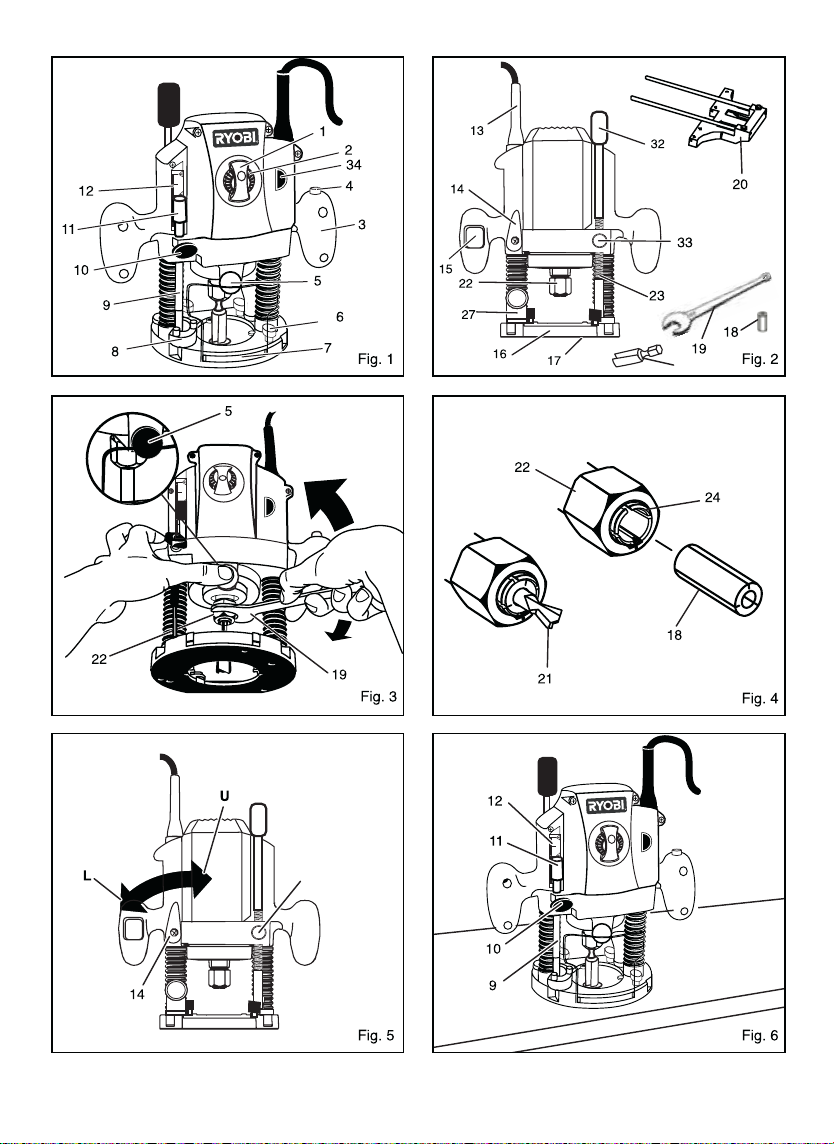
DESCRIPTION
1. Speed selection
sight window
2. Variable speed control
3. Handle
4. Lock-off button
5. Spindle lock button
6. Parallel guide lock knob
7. Chip shield
8. Depth stop
20. Parallel guide
21. Cutter
22. Collet nut
23. Threaded post
24. Collet
25. Router bits
26. Work-piece
27. Dust port
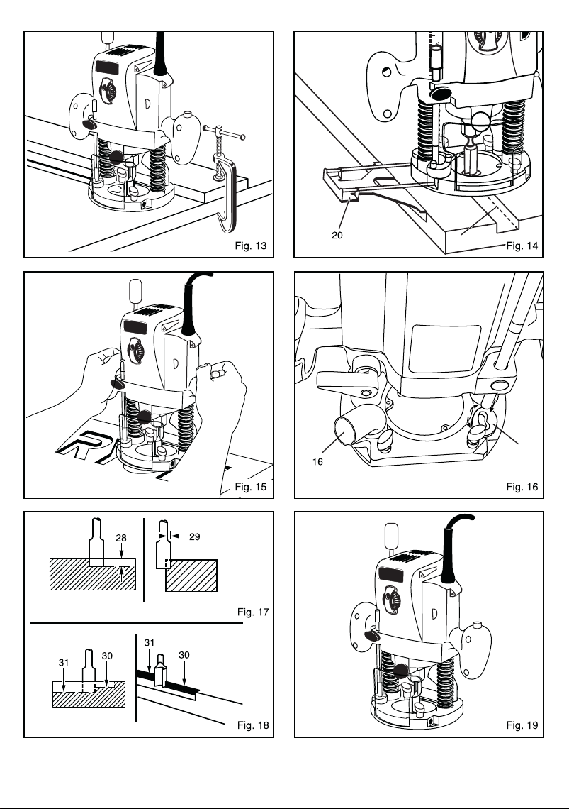
28. Depth of cut
9. Depth stop bar
29. Width of cut
10. Depth stop bar lock knob
30. 1st pass
11. Depth zero reset indicator
31. 2nd pass
12. Scale
32.
Fine height adjuster knob
13. Power cord
33. Fine height adjuster
14. Plunge lock lever
quick release button
15. Switch
34. Livetool Indicator
TM
16. Router base
35. Template guide
17. Sub-base
36. Screw
18. Collet adaptor
19. Spanner 23.8mm
APPLICATIONS
Use your router only for the purposes listed below:
■
Routing grooves, shaping edges, freehand designs,
etc. in wood.
■
Chamfering, rabbeting, dadoing, and dovetailing in
wood.
■
Routing edges on laminates.
FEATURES
Your plunge router is a versatile woodworking tool that
will give you years of trouble-free performance. It is
engineered with the professional in mind, but its ease
of operation allows the amateur to produce work that is
beautiful and precise. As the name implies your plunge
router can be used for making plunge cuts in workpieces,
routing grooves, edge routing, routing circles and freehand
routing. When used with recommended accessories, such
as a router table, depth adjustment knob and straight guide;
it becomes even more versatile. Various types of cutters,
both with and without roller bearings as guides, also add
to the versatility of this tool.
HEAVY DUTY MOTOR
Your router has a powerful motor with sufficient power to
handle tough routing jobs. It delivers 1.5 horsepower for
heavy duty performance.
CHIP SHIELD
A plastic chip shield has been provided on the base of
your router for protection against flying dust and chips.
It is designed to fit the front opening of the router base.
SPINDLE LOCK
The spindle lock secures the spindle so that only one
wrench is needed to loosen collet nut and change
cutters. To operate push the button whilst loosening the
collet nut. NOTE: Do not run router with spindle lock engaged.
SPECIFIC SAFETY RULES
Peak horsepower : 1.5 HP
Net weight : 4.5 kg.
37. Locking anchor
Page 9

4
FEATURES
VARIABLE SPEED
Your router has advanced electronic features, designed to
assist you in getting the maximum use from your router.
By making proper speed selections, your router can be
adjusted to specific routing needs.
The variable speed control allows the router to develop a
no load speed that can be adjusted from 14,000 to 31,500
min-1. The variable speed control selector is conveniently
located on the front of the router.
The electronic feature of your router introduces the flexibility
of adjusting the motor speed to required
job conditions. An
electronic speed control module senses the load applied
to the motor and increases or decreases motor voltage to
compensate for and maintain desired RPM.
Speed can be
set according to the approximate cutter diameter you will
be using and to the hardness of the material being cut. The
best cuts are made when the cutter is fed through material
at the proper rate of feed.
PLUNGE LOCK LEVER
Your router has a plunge lock lever that allows for free
plunging. This feature is very useful for table mounted
operations on router tables when used with the fine height
adjuster quick release mechanism. Unlocking the plunge
lock lever and releasing the fine height adjuster allows for
a smooth, precise plunging action. Once you reach the
desired depth of
cut, simply lock the plunge lock lever. The
cutter will then be secured at the desired depth of cut.
After extended use, the plunge lock may wear. If this
happens, you can easily adjust the lever.
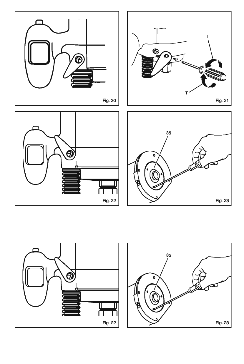
TO ADJUST PLUNGE LOCK LEVER (FIG. 21)
■
UNPLUG YOUR ROUTER.
WARNING:
Failure to unplug your router could result in
accidental starting causing serious injury.
■
Make sure lever is in locked position.
■
Remove (L) the screw supporting the plunge lock
lever.
■
Remove the lever.
■
Place the lever back in the original locked position.
■
Replace (T) the screw.
■
Check for free plunge with lever rotated to unlocked
position. If router does not plunge freely, reposition
lever.
PLUNGE LOCK LEVER SHOWN AFTER
EXTENDED WEAR (FIG. 20)
PLUNGE LOCK LEVER SHOWN IN ORIGINAL
LOCKED POSITION (FIG. 22)
TEMPLATE GUIDE (FIG. 23)
The template guide (35) can be fitted to the base of the
router to accurately duplicate curves and other complex
shape. These shapes can be easily made by using a jigsaw
to cut out a template. Fix the guide to the base of the router
by placing the guide in the recess provided in the base
and inserting the 3 screws provided. The guide protrudes
below the bottom of the base allowing the router to follow the
template, which must be securely fixed to the workpiece and
a firm pressure applied to the router at all times to ensure
that the edge of the guide accurately follows the template.
The template must be at least 5mm thick to allow for the
protrusion of the guide. Allowance must also be made in
the template for the distance between the cutting edge of
the bit and the outside edge of the template guide.
ERGONOMIC DESIGN
The design of this tool provides for easy handling. It is
designed for comfort and ease of grasp when operating
in different positions and at different angles.
ELECTRICAL CONNECTION
Your router has a precision built electric motor. It should
only be connected to a power supply of the type specified
on the rating plate of the machine, AC only. Do not operate
this tool on direct current (DC). A voltage drop of more than
10 percent will cause a loss of power and overheating.
If your tool does not operate when plugged into an outlet,
double-check the power supply.
DOUBLE INSULATION
Double insulation is a concept in safety in electric power
tools, which eliminates the need for the usual threewire grounded power cord. All exposed metal parts are
isolated from the internal metal motor components with
protecting insulation. Double insulated tools do not need
to be grounded.
Page 10

FEATIRES
5
ADJUSTMENTS
WARNING:
Your router should never be connected to power
supply when you are assembling parts, making
adjustments, installing or removing cutters or
when not in use. Disconnecting your router will
prevent accidental starting that could cause
serious injury.
CUTTER INSTALLATION (FIG. 3 & 4)
■
UNPLUG YOUR ROUTER.
WARNING:
Failure to unplug your router could result in
accidental starting causing serious injury.
CAUTION:
To prevent damage to the spindle or spindle
lock, always allow motor to come to a complete
stop before engaging spindle lock.
■
Remove chip shield (7) from router base (16).
■
Depress spindle lock (5).
■
Lay router down on workbench in order to gain easy
access to collet nut (22). Place the spanner (19)
provided through front of router
and turn counterclockwise to loosen.
base onto collet nut
WARNING:
The double insulated system is intended to
protect the user from shock resulting from a
break in the tools internal wiring. Observe all
normal safety precautions to avoid electrical
shock.
Important: Servicing of a tool with double insulation
requires extreme care and knowledge of the system and
should be performed only by a qualified service
technician. For service, we suggest you return the tool to
your nearest authorized service center for repair.
WARNING:
Do not attempt to modify this tool or create
accessories not recommended for use with
this tool. Any such alteration or modification
is misuse and could result in a hazardous
condition leading to possible serious personal
injury.
ADJUSTMENTS
FEATURES
WARNING:
Your router should never be connected to power
supply when you are assembling parts, making
adjustments, installing or removing cutters or
when not in use. Disconnecting your router will
prevent accidental starting that could cause
serious injury.
CUTTER INSTALLATION (FIG. 3 & 4)
■
UNPLUG YOUR ROUTER.
WARNING:
Failure to unplug your router could result in
accidental starting causing serious injury.
CAUTION:
To prevent damage to the spindle or spindle
lock, always allow motor to come to a complete
stop before engaging spindle lock.
■
Remove chip shield (7) from router base (16).
■
Depress spindle lock (5).
■
Lay router down on workbench in order to gain easy
access to collet nut (22). Place the spanner (19)
provided through front of router
and turn counterclockwise to loosen.
base onto collet nut
WARNING:
If you are changing a cutter immediately after
use, be careful not to touch the cutter or collet
with your hands or fingers. They will get burnt
because of the heat buildup from cutting. Always
use the wrench provided.
■
Install cutter (21) once collet nut is loose. If changing
cutters, cutter will easily slip from collet (24) after
loosenin g c oll et nut. For ex amp le: The collet is
machined to precision tolerances to fit cutters with
12.7 mm diameter shanks. To use cutters with 6.35 mm
diameter shanks, insert the 6.35 mm collet adaptor (18)
into the 12.7 mm collet.
■
Insert shank of cutter until shank bottoms out, then pull
it out 1.6 mm to allow for expansion when the bit get hot.
■
Tighten the collet nut securely by turning clockwise
with the wrench provided.
■
Release spindle lock.
■
Replace chip shield.
WARNING:
If the collet nut is not securely tightened, the cutter
may detach during use causing serious personal
injury.
WARNING:
Do not use cutters with undersized shanks.
Undersized shanks will not tighten properly and
could be thrown from the tool causing injury.
WARNING:
Do not use cutters that are larger in diameter
than the opening in router base. Use of such
cutters will come in contact with the router base
and damage both the cutter and router base.
This situation could also cause possible loss of
control or create other hazardous conditions that
could cause possible serious personal injury.
DEPTH OF CUT
When routing a groove that is too deep to safely cut in
one pass, it is best to make the cut in several passes.
We recommend that cuts be made at a depth not
exceeding 3.2 mm and that several passes be made to
reach deeper cuts.
Proper depth of cut depends on several factors
Page 11

6
horsepower of router motor, type of cutter being used and
type of wood being routed. A lightweight, low horsepower
router is designed for making shallow cuts. A router with
h
igh horsepower rating can safely cut
deeper. For example:
small bits (21), such as veining b
its with 1.6mm cutting
diameters, are
designed to remove only small amounts or
small amounts of wood. Large bits, such as straight-flute
b
its, are made to remove
larger amounts of wood in a single
pass. Cuts can be
made deeper in soft woods, such as
white pine, than in
tough hardwoods, like oak or maple.
Based upon these considerations, choose a depth of cut
that will not place excessive strain on router motor. If you
fi
nd that extra
force is needed or that the motor speed
slows down
considerably, turn off router and reduce the
depth of cut.
Then, make the the cut in two or more passes.
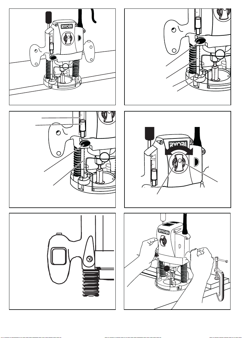
TO ADJUST DEPTH OF CUT (FIG. 5-7)
■
Loosen the stop bar (9)
■
Unlock (U) the plunge lock lever (14).
■
Lower the router body until the cutter is in contact with
the work-piece.
■
Lock the depth stop (8) at the right height.
■
Set the exact depth of cut using the graduation. The
distance between the stop bar (9) and screw of the
depth stop (8) is setting plunge depth.
■
Tighten the stop bar lock knob (10) to set depth of
plunge.
DEPTH STOP (FIG. 8 & 9)
■
The depth stop (8) can be used to set three different
depths. This is particularly useful for deep cuts
performed in steps.
■
If required, set all three screws.
VARIABLE SPEED CONTROL SELECTOR
(FIG. 10)
Your router has a variable speed control selector (2)
designed to allow operator control of speed and torque
l
imits. Yo
u can make speed selections best suited to
the type of cut, the material being cut, and the size of bit
b
eing u
sed. The variable speed control selector allows
ADJUSTMENTS
you to adjust router speed from 14,000 to 31,500 min-1.
There is a six step scale (A to F) on the variable speed
control selector. To increase the speed and torque of your
router, turn the variable speed control selector to a higher
s
etting (F). Tu
rn to a lower setting to decrease speed
and torque.
NOTE: If you do not want to use the variable speed control
selector, turn it to the highest possible setting, and the
feature will not be active.
We s
uggest that you practice with the variable speed
feature of your router before installing a cutter and making
cuts in wood.
ZERO RESET INDICATOR
The zero reset indicator(11) allows you to use the scale
provided o
n the housing to make quick depth of cut
changes to existing depth of cut settings. Simply choose
a reference point on the scale and slide the zero reset
indicator up or down the scale the distance required for
n
ew d
epth of cut. Then change stop bar position by
loosening lock knob and adjusting stop bar until red line
on zero reset indicator moves back to reference point.
Ti
ghten lock knob securely to lock stop bar in new position.
The c
utter position will now increase or decrease the exact
distance the stop bar was adjusted.
NOTE: Each mark on the inch scale indicates 1.6 mm.
OPERATION
SWITCH (FIG.11)
To turn the router ON, press the lock-off button (4) and
squeeze the switch (15). To turn the router OFF, release
both the switch & lock-off button.
CAUTION:
We suggest that you practice with your router
before installing a cutter and making cuts in
wood.
Livetool IndicatorTM (34)
This tool features a Livetool IndicatorTM which illuminates
as soon as the tool is connected to the power supply. This
warns the user that the tool is connected to live power
and will operate when the switch is pressed.
ROUTING (FIG. 12)
For ease of operation and maintaining proper control,
your router has two handles (3), one on each side of the
Page 12

7
router. When using your router hold it firmly with both
hands.
Before starting the router, unplug it and make sure the
cutter is securely tightened in collet nut and that depth of
cut is properly set.
Plug router into power supply, turn it on and let motor
build to its full speed, then gradually plunge or feed cutter
into workpiece. Do not let the cutter contact workpiece
before turning on router and allowing it to develop full
speed.
Remain alert and watch what you are doing. Do not operate
router when fatigued or under the influence of drugs,
alcohol or any medication.
ROUTING GROOVES (FIG. 13)
When routing across the face of boards, set router at
desired depth of cut, place the edge of router base against
workpiece and turn on the router. Slowly feed the cutter
into the workpiece along desired line of cut.
WARNING:
If desired depth of cut is greater than can be
safely cut in one pass, make cuts in two or more
passes.
When routing straight cuts across timber, clamp a straight
edge to the workpiece to use as a guide. Position the
straight edge parallel to the line of cut and offset the
distance between the cutting edge of the cutter and the
edge of the router base. Hold the route base against
the straight edge and route the groove.
When routing a groove wider than the diameter of the
cutter, clamp a straight edge on both sides of the cutlines. Position both guides parallel to the desired line of
cut and spaced equal distances from the desired edges
of the groove. Route along one guide; then, reverse
direction and route along the other guide. Clean out any
remaining waste in the center of the groove freehand.
FITTING AND ADJUSTING THE PARALLEL
GUIDE (FIG. 14)
■
Insert the parallel guide (20) into the hole of the Router
base (16).
■
Draw a cutting line on the work-piece (26).
■
Lower the router body until the cutter is in contact
with the work-piece.
OPERATION
■
Postion the router on the cutting line. The outer cutting
edge of the cutter must coincide with the cutting line.
■
Without moving the router push the guide to the edge
of the workpiece before tightening the lock knob (6).
ROUTING BY FREEHAND (FIG. 15)
When used freehand, your plunge router becomes a
flexible and versatile tool. This flexibility makes it possible to easily route signs, relief sculptures, etc. There are
two basic techniques for freehand routing:
■
Routing letters, grooves and patterns into wood.
■
Routing out the background, leaving the letters or
pattern raised above the surface.
When freehand routing, we suggest the
following:
■
Draw or layout the pattern on workpiece.
■
Choose the appropriate cutter.
NOTE: A core box or V-groove bit is often used for
routing letters and engraving objects. Straight bits
and ball mills are often used to make relief carvings.
Veining bits are used to carve small, intricate details.
■
Route the pattern in two or more passes. Make the
first pass at 25% of the desired depth of cut. This
process will provide better control as well as being a
guide for the next pass.
■
Do not route deeper than 3.2 mm per pass or cut.
Follow these directions when routing by
freehand:
■
Choose the appropriate cutter, set desired depth of
cut, carefully check set-up, and secure workpiece.
■
Make a test cut in a scrap piece of wood from the
same workpiece if possible.
■
Unlock plunge lock lever to raise cutter from any preset
depth of cut. This also permits raising cutter inside
router base.
■
Place router on wor kpi ece ins ide patter n to be
routed.
■
Grasp handles securely and press the switch to start
your router.
Page 13

OPERATION
■
Let motor build to full speed, then gradually plunge
cutter into workpiece until stop bar comes into contact
with depth stop.
■
Lock plunge lock lever to secure depth of cut setting.
■
Begin routing out the pattern, continuing until a
complete pass at this depth of cut has been made.
WARNING:
Do not use large router bits for freehand routing.
Use of large router bits when freehand routing
could cause loss of control or create other
hazardous conditions that could cause possible
serious personal injury.
■
Several cuts that require repositioning of router may
be needed for a particular job. If this situation exists,
unlock plunge lock lever to raise cutter inside router
base after each cut, reposition router for next cut,
gradually plunge cutter into workpiece until stop bar
c
ontacts depth stop, lock plunge lock lever and continue
routing.
■
■
After all cuts have been made, unlock plunge lock
lever, raise cutter inside router base, remove router
from workpiece, turn off the router and allow cutter to
come to a complete stop.
ROUTING EDGES
Place router on workpiece, making sure the router bit
does not contact workpiece. Turn router on and let the
m
otor b
uild to its full speed. Begin your cut, gradually
feeding cutter into workpiece.
WARNING:
Keep a firm grip on router with both hands at all
times. Failure to do so could result in loss of
control leading to possible serious injury.
Upon completion of cut, turn motor off and let it come to
a complete stop before removing router from work
surface.
WARNING:
Never pull router out of work and place upside
down on work surface before the cutter stops.
CONNECTING A DUST EXTRACTOR (FIG. 16)
The dust extractor hose can be connected to the dust
extraction port located on the base with a 25.4mm O.D.
FINE HEIGHT ADJUSTER (32)
It is used to precisely control the depth of the cutter.
■
To use the fine height adjuster, ensure that the
plunge lock is released.
■
Ro tat e the knob clockw ise to rai se the cut ter,
anticlockwise to lower the cutter.
■
When the desired position is reached, re-engage the
plunge lock before use.
FINE HEIGHT ADJUSTER QUICK RELEASE
BUTTON (33)
This disengages the fine height adjuster allowing a large
adjustments of plunge depth to be quickly made.
■
To make large adjustments to cutter height, ensure
that the plunge lock is released.
■
Press the quick release button whilst plunging the
router to the required height.
■
Release the button, check the height, make fine
adjustments if necessary with the fine height adjuster,
then re-engage the plunge lock before use.
8
LOCKING ANCHOR FOR THREADED FINE
HEIGHT ADJUSTMENT ROD (FIG. 16)
The locking anchor (37) is located on the base of the router,
it is designed to hold the threaded fine height adjustment
rod in place to allow the fine height adjustment to
operate. When the fine height adjustment is required,
release the fine height adjuster quick release button and
push down on the fine height adjuster knob so that the
bottom of the threaded rod makes contact with the base
and locking anchor. Make sure the locking anchor is
positioned so that the bottom of the threaded rod goes into
the right hand side of the elongated hole (the larger side
of the opening). Once in place turn the locking anchor to
the right to secure the threaded rod. To release, turn the
locking anchor to the left and push the fine height
adjuster quick release button and pull the fine height
adjuster knob upwards.
Page 14

9
MAINTENANCE
WARNING:
When servicing use only identical Ryobi replace-
ment parts. Use of any other parts may create a
hazard or cause product damage.
GENERAL
Avoid using solvents when cleaning plastic parts. Most
plastics are susceptible to damage from various types of
commercial solvents and may be damaged by their use.
Use clean cloths to remove dirt, carbon dust etc.
WARNING:
Do not at any time let brake fluids, petrol, petroleum
- based products, penetrating oils etc. come in
contact with plastic parts. They contain chemicals
that can damage, weaken or destroy plastic.
Electric tools used on fiberglass material, wallboard,
spackling compounds or plaster are subject to
acelerated wear and possible premature failure, as the
fiberglass chips and grindings are highly abrasive to
bearings, brushes, commutators etc. Consequently, we
do not recommended that this tool be used for extended
work on these types of materials. If, however, you do
work with any of these materials, it is extremely important that you clean the tool frequently by blowing it with
an air jet.
WARNING:
Always wear safety goggles or safety glasses
with side shields during power tool operation or
when blowing dust. If operation is dusty, also
wear a dust mask.
LUBRICATION
All of the bearings in this tool are lubricated with a sufficient
amount of high grade lubricant for the life of the unit under
normal operating conditions. Therefore, no further lubrication
is required.
CUTTERS
Get faster and more accurate cutting results by keeping
cutters clean and sharp. Remove all accumulated pitch
and gum from cutters after each use.
When sharpening cutters, sharpen only the inside of the
cutting edge. Never grind the outside diameter. Be sure
when sharpening the end of a cutter to grind the
clearance angle the same as originally ground.
COLLET
Dust and chips may collect on the collet from time to time,
making it necessary to clean the collet. To do so, remove
the collet assembly and wipe it with a clean dry cloth.
Clean the taper in the shaft in the same manner. Never
immerse the collet or end of the shaft in a solvent or in
water. Before replacing the collet assembly, put a drop
of motor oil on the inside of the nut, on the threads of the
shaft and on the taper in the shaft. Replace the collet
assembly onto the shaft by hand only. Never tighten the
collet nut without a bit in the collet. This action could
permanently damage the collet.
ADJUSTMENTS
DEPTH OF CUT
As previously mentioned, the depth of cut (30) is important
because it affects the rate of feed that, in turn, affects the
quality of the cut (and also, the possibility of damage to
your router motor and bit). A deep cut requires a slower
feed than a shallow one, and a too deep cut will cause
you to slow the feed so much that the bit is no longer
cutting, it is scraping, instead.
Making a deep cut is never advisable. The smaller bits
— are easily broken off when subjected to too much side
thrust. A large enough bit may not be broken, but if the
cut is too deep a rough cut will result — and it may be very
difficult to guide and control the bit as desired. For these
reasons, we recommend that you do not exceed 3.2 mm
depth of cut in a single pass, regardless of the bit size or
the softness or condition of the workpiece. To make deeper
cuts it is therefore necessary to make as many successive
passes as required, lowering the bit 3.2mm for each new
pass. In order to save time, do all the cutting necessary
at one depth setting, before lowering the bit for the next
pass. This will also assure a uniform depth when the final
pass is completed.
Page 15

RYOBI TECHNOLOGIES AUSTRALIA PTY. LTD.
GUARANTEE
RYOBI TECHNOLOGIES AUSTRALIA PTY. LTD.
A.B.N. 98 002 277 509
SYDNEY: 359-361 Horsley Road, Milperra, N.S.W. 2214.
Contact during normal business hours.
RYOBI NEW ZEALAND PTY. LTD.
AUCKLAND: 27 Clemow Drive, Mt Wellington, N.Z.
Contact during normal business hours.
Subject to the guarantee condition below, this Ryobi tool
(hereinafter called “the product”) is guaranteed by Ryobi
(hereinafter called “the Company”) to be free from
defects in material or workmanship for a period of 24
months from the date of original purchase covering
both parts and labour. Under the terms of this
guarantee, the repair or replacement of any part shall
be the opinion of the Company or its authorised agent.
Should service become necessary during the warranty
period, the owner should contact the RYOBI HELPLINE
1300 361 505 or contact the retailer from whom the
product was purchased.
In order to obtain guarantee service, the owner must
present the sales docket and Guarantee Certificate
to confirm date of purchase. This product is sold by the
dealer or agent as principal and the dealer has no
authority from the Company to give any additional
guarantee on the Company’s behalf except as herein
contained or herein referred to.
Guarantee Conditions
This guarantee only applies provided that the Product
has been used in accordance with the manufacturer’s
recommendations under normal use and reasonable
care (in the opinion of the Company) and such
guarantee does not cover damage, malfunction or
failure resulting from misuse, neglect, abuse, or used
for a purpose for which it was not designed or is not
suited and no repairs, alterations or modifications
have been attempted by other than an Authorised
Service Agent. This guarantee will not apply if the tool is
damaged by accident or if repairs arise from normal
wear and tear.
The Company accepts no additional liability pursuant to
this guarantee for the costs of travelling or
transportation of the Product or parts to and from the
service dealer or agent - such costs are not included in
this guarantee.
Certain legislation, including the Trade Practices Act,
1974 (as amended) and other state and territorial laws
give rights to the buyer and impose liability on the seller in
certain circumstances. Nothing herein shall have the effect
of excluding, restricting or modifying any condition,
guarantee, right or liability imposed, to the extent only
that such exclusion, restriction or modification
would render any term herein void.
BRISBANE : All enquiries Tel : 1300 361 505
TOWNSVILLE: All enquiries Tel : 1300 361 505
MELBOURNE: 960 Stud Road, Rowville,Vic. 3178
Tel : (03) 9764 8656
HOBART: All enquiries Tel : 1300 361 505
ADELAIDE: All enquiries Tel : 1300 361 505
PERTH: 33-35 Sorbonne Cres. Canning Vale, W.A. 6155
Address Of Dealer
Present This Form With Your Purchase Docket When Guarantee Service Is Required.
Tel: (02) 9792 9800 - Fax: 1800 807 993 - www.ryobi.com.au
Tel: (09) 573 0230 - Free Call: 0800 279 624 - Fax: (09) 573 0231 - www.ryobi.co.nz
Tel : (08) 9455 7775
This Guarantee Form Should Be Retained By The Customer At All Times
For your record and to assist in establishing date of purchase (necessary for in-guarantee service)
please keep your purchase docket and this form completed with the following particulars.
Date Model No Serial No
 Loading...