

Page 1
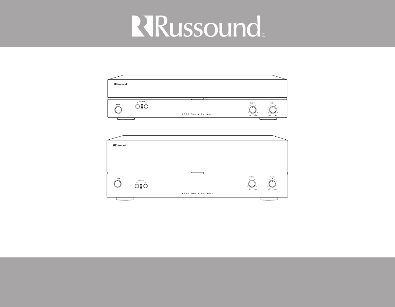
X125 - X225
Dual Source Power Ampliers
Installation Manual
Page 2
SAFETY INSTRUCTIONS
WARNING: TO REDUCE THE RISK OF FIRE
OR ELECTRIC SHOCK, DO NOT EXPOSE THIS
APPLIANCE TO RAIN OR MOISTURE.
CAUTION: TO REDUCE THE RISK OF ELECTRIC
SHOCK, DO NOT REMOVE THE COVER. NO USERSERVICEABLE PARTS INSIDE. REFER SERVICING
TO QUALIFIED SERVICE PERSONNEL.
The lightning ash with arrowhead symbol, within an
equilateral triangle, is intended to alert the user to the
presence of uninsulated dangerous voltage within the
product’s enclosure that may be of sucient magnitude
to constitute a risk of electric shock to persons.
The exclamation point within an equilateral triangle is
intended to alert the user to the presence of important
operating and maintenance (servicing) instructions in the
literature accompanying the appliance.
Safety Instructions
Read Instructions - All the safety and operating 1.
instructions should be read before the appliance is
operated.
Retain Instructions - The safety and operating 2.
instructions should be retained for future reference.
Heed Warnings - All warnings on the appliance in the 3.
operating instructions should be adhered to.
Follow Instructions - All operating and user 4.
instructions should be followed.
Water and Moisture - The appliance should not 5.
be used near water; for example, near a bathtub,
washbowl, kitchen sink, laundry tub, in a wet
basement, or near a swimming pool. The apparatus
shall not be exposed to dripping or splashing liquids
and no objects lled with liquids, such as vases, shall
be placed on the apparatus.
Carts and Stands - The appliance should 6.
be used only with a cart or stand that is
recommended by the manufacturer.
An appliance and cart combination
should be moved with care. Quick
stops, excessive force and uneven
surfaces may cause the appliance and
cart combination to overturn.
Location of the Amplier - Do not mount this unit 7.
under a kitchen cabinet. Do not expose the amplier
to direct sun light or heating units as the amplier
internal components’ temperature may rise and
shorten the life of the components. Avoid damp and
dusty places.
Ventilation - The appliance should be situated so 8.
that its location or position does not interfere with
its proper ventilation. For example, the appliance
should not be situated on a bed, sofa, rug, or similar
surface that may block the ventilation openings, or
placed in a built-in installation, such as a bookcase or
cabinet that may impede the ow of air through the
ventilation openings.
Heat - The appliance should be situated away from 9.
heat sources such as radiators, heat registers, stoves,
or other appliances (including ampliers) that
produce heat.
Power Sources - The appliance should be connected 10.
to a power supply only of the type described in
the operating instructions or as marked on the
appliance.
Grounding or Polarization - Precaution should be 11.
taken so that the grounding or polarization means of
an appliance is not defeated.
Power Cord Protection - Power supply cords should 12.
be routed so that they are not likely to be walked
on or pinched by items placed upon or against
them, paying particular attention to cords at plugs,
receptacles, and the point where they exit from the
appliance.
Main Power Disconnect - The power switch is a single-13.
pole switch. When the switch is in the “O” position,
the appliance is not completely disconnected from
the main power. The main power plug is used as the
disconnect device and shall remain readily operable.
When installing the product, ensure that the plug is
easily accessible.
Cleaning - The appliance should be cleaned only as 14.
recommended by the manufacturer.
Non-Use Periods - The power cord of the appliance 15.
should be unplugged from the outlet when left
unused for a long period of time. To remove all power
(supply mains) from the appliance, remove the plug
from the wall outlet.
Object and Liquid Entry - Care should be taken so that 16.
objects do not fall and liquids are not spilled into the
enclosure through the openings.
Servicing - The user should not attempt to service the 17.
appliance beyond that described in the operating
instructions. All other servicing should be referred to
qualied service personnel.
Damage Requiring Service - The appliance should be 18.
serviced by qualied service personnel when:
A. The power supply cord or the plug has been
damaged.
B. Objects have fallen, liquid has been spilled into the
appliance;
C. The appliance has been exposed to rain; or
D. The appliance does not appear to operate
normally; or
E. The appliance has been dropped or the enclosure
is damaged.
2 Russound X125-X225 Installation Manual Rev. 1
Page 3

Safety Instructions ..................................................................................................................2
Product Overview ..................................................................................................................4
Front and Rear Panels ............................................................................................................5
System Conguration - Stereo Mode ............................................................................... 6
System Diagram - Stereo Mode..........................................................................................7
System Conguration - Bridged Mode ............................................................................ 8
System Conguration - External Volume Control ........................................................ 9
Technical Specications ......................................................................................................10
Warranty ...................................................................................................................................11
TABLE OF CONTENTS
Rev. 1
Russound X125-X225 Installation Manual
3
Page 4

PRODUCT OVERVIEW
Introduction
The Russound X125 and X225 are 2-channel dual source power ampliers with
auto-source switching. Each features Primary and Secondary audio line inputs
with a loop out to another zone, receiver, or device from the secondary source.
A speaker-level input can be connected and assigned as either the primary or
secondary source. This amplier can be used for power upgrades in zones for
large speaker selector or volume control systems.
The X125 is rated at 125 watts per channel into 4 ohms, and 80 watts into 8
ohms. The X225 is rated at 225 watts per channel into 4 ohms, and 150 watts
into 8 ohms. Each amplier output channel incorporates robust protection
circuitry for reliability and safety under extreme circumstances.
With the Stereo/Bridge Mono switch in the Bridge Mono position, both
amplier channels are combined for a higher powered mono output. In Bridge
mode the X125 is rated at 250 watts of power into a single 8 ohm load, and the
X225 is rated at 470 watts of power into a single 8 ohm load.
The 12V Trigger In/Out allows each amplier to be activated by other devices
or to activate other electronics via a 3.5 mm mini phone plug cable, with 100mA
current capability.
Thermal Protection
All X Series ampliers are designed with special circuitry to safeguard the
amplier under a thermal overload condition. Thermal protection mode will
only engage when the unit has been run at high volume for extended periods of
time without adequate ventilation and/or when speaker impedances are below
the minimum levels for the amplier. In thermal protection mode the amplier
will automatically stop output. If this fault occurs, turn o the amplier, and
check that the speaker impedance rating is above the minimum rating. Also
check for adequate ventilation around the amplier and make adjustments
if necessary. Once the unit has cooled to safe operating temperatures, the
amplier may be powered back on.
Protection Circuitry
Special circuitry has been designed into the amplier to safeguard under a
short-circuit condition. A faulty speaker can also cause a short circuit condition.
If this fault condition occurs, turn o the amplier and check speakers for short
circuit conditions when appropriate. The amplier power must be cycled for
the unit to return to normal operation.
Installation
The ampliers can be placed on a shelf in an equipment rack or on a table
or cabinet. Be sure to leave at least 2 inches of space around each side of the
amplier to allow for ventilation and heat dissipation.
Front Panel Controls
On the front panel of the X125 and X225 ampliers are the power button plus
speaker selector, balance and volume adjustment.
Power - the front panel switch will manually switch the power on or o.
Speaker selector - select speaker pair A (main) or speaker pair B (auxiliary) for
audio output. You can use speakers A and B together, as long as the speakers
are at a minimum 8-ohm impedance.
Balance - adjust speaker output balance between right and left channels. The
default setting is at center.
Volume - adjust the speaker output volume. If using Bridged mode, set the
volume at minimum, then adjust to the desired level.
Power On - Manual, Auto, Remote
The X125 and X225 ampliers can be turned on manually or automatically by
setting a switch on the rear panel. For manual power on or o, set the switch to
Normal and press the Power button on the front panel. For automatic power on,
set the switch to Auto On. When music is sensed on any input, the amplier's
signal sensing sends a command for it to power on. Once the signal ends, the
amplier turns o in about 4 minutes. To turn the amplier on remotely, set
the switch to Trigger and connect a 3.5mm phone plug remote triggering wire
from the device to the 12V Trigger In on the amplier.
NOTE: The front panel Power button must be in the "On" position for the 12V
trigger and Auto On features to work.
Speaker Cable
When connecting speakers to the ampliers, use a minimum 16 gauge and
maximum 12 gauge stranded copper cable. Avoid leaving stray strands and
keep polarity consistent.
4 Russound X125-X225 Installation Manual Rev. 1
Page 5

FRONT AND REAR PANEL
Primary Input
Power button Speaker selector
Speaker Level Line
Input Switch
Speaker Level Input
(Spring Connector)
Secondary Input/Output
Delay
Time
Right/Left
Channel
Controls
X125 Front Panel
Stereo/Bridge
Switch
X125 Rear Panel
12V Trigger
In / Out
Balance control
Power Option
Switch
Speaker Output
Volume control
Power Inlet /
Fuseholder
Voltage
Selector
Rev. 1
Russound X125-X225 Installation Manual
5
Page 6

SYSTEM CONFIGURATION STEREO MODE
Stereo Mode (Single Source)
The X125 and X225 can be congured as a power upgrade for specic zones,
for use with large speaker selectors, and for long parallel speaker runs (outdoor
zones). For a single source connection:
Unplug the amplier.1.
Set the Stereo/Bridge switch to Stereo.2.
Connect the audio line output from a stereo preamplier or source to the 3.
left and right Secondary input jacks of the amplier. If the output is only
available as speaker level see "Speaker Level Signal" section below.
Connect your speakers to the terminals, observing proper polarity.4.
Restore power to the amplier. Both channel levels can be adjusted with 5.
the corresponding channel level adjustments.
Dual source connections
The X125 and X225 have dual source capability. If two sources are used,
connect the source you want to take temporary priority to the Primary input
and the other constant source to the Secondary input.
Whenever the primary source becomes active, that signal will take priority
over the distributed audio signal on the secondary line. The signal is still active
on the secondary line but will not be heard, and once the primary audio signal
is muted or turned o the amplier will automatically switch back to the
secondary audio signal. For dual source connections:
1. Connect the source audio outputs to both Primary and Secondary inputs
as instructed above.
2. Set the switching delay with the Delay Time knob. This adjustment
determines the length of time it takes to switch back to the secondary signal.
For example, if the primary source is a CD changer, increasing the delay time
will prevent a switch back to the secondary source while the disc is changing.
Note: This works with all incoming signals, line level or speaker level.
Speaker Level Signal
If you have a source that is only available as a speaker level signal, connect it to
the Speaker Level Input terminals, using the spring loaded terminal block and
observing proper polarity. Only one set of speaker level inputs can be utilized
and assigned by the selector switch.
Set the switch to Primary or Secondary. This forces the input to act as either
the primary or secondary input.
Only one type of input (speaker or line) should be assigned to each input.
When using the Speaker Level Input, and it is switched to the Secondary
position, the high-level signal will not pass to the Secondary Line RCA output.
6 Russound X125-X225 Installation Manual Rev. 1
Page 7

X125 Amplier
Line Out
RCA Cable
CD Player (primary source)
Multiroom Controller (secondary source)
Speaker Cables
8 Ohm Speakers
Speaker Cables
SYSTEM DIAGRAM STEREO MODE
Rev. 1
Stereo Mode Conguration with Dual Sources
(CD player is primary source)
Russound X125-X225 Installation Manual
7
Page 8

SYSTEM CONFIGURATION BRIDGED MODE
X125 Amplier
Line Out from source
(+) Positive Conductor
(-) Negative Conductor
8 Ohm Speaker
Switch set to Bridged Mode
Bridged Mode
In this mode both the left and right channels are combined for a higher power
mono output. For proper operation, the Master Level left and right channel
adjustment on the back panel should be set to the center position to start and
then adjusted appropriately from there.
Unplug the amplier. 1.
Set the Stereo/Bridge switch to Bridge Mono. 2.
Connect the line out from a preamplier or source to the Left and Right 3.
Primary input jacks of the amplier.
Connect the negative lead (-) of the speaker cable to the R(+) terminal. 4.
Connect the positive lead (+) of the speaker cable to the L(+) terminal. (See
the markings above the terminals on the rear panel). An 8 Ohm minimum
load is recommended.
Restore power to the amplier.5.
Be sure to equally adjust the Master Level right and left. 6.
Bridged Mode Connection Detail
Bridged Mode Conguration
8 Russound X125-X225 Installation Manual Rev. 1
Page 9

Line Out from Source
X225 Amplier
INPUT
EXPANSIONS
SPEAKERS SPEAKERS
SPEAKERS SPEAKERS
RUSSOUND
INPUT
EXPANSIONS
SPEAKERS SPEAKERS
SPEAKERS SPEAKERS
RUSSOUND
Autoformer-based
Volume Control
EZB-1SC Modular
Connecting Block
IN
8 Ohm Speaker
NOTE: For more than four volume controls,
add EZB-2SC Modular Connecting
Block expander
Autoformer-based
Volume Control
IN
8 Ohm Speaker
Speaker Cable
Speaker Cable
Speaker Cable
Speaker Cable
System Conguration with External Volume Control
The X125 and X225 ampliers can be congured for large autoformer-based
volume control systems or speaker selectors. Connect up to eight (total)
impedance matching volume controls to the amplier on speaker A and B
outputs (e.g., 8 on 'A' and none on 'B', 4 on 'A', 4 on 'B', etc.)
SYSTEM CONFIGURATION EXTERNAL VOLUME CONTROL
Each amplier has a minimum 4-ohm load in stereo mode, and minimum
8-ohm load in bridged mode.
Rev. 1
Conguration with Autoformer Volume Control
Russound X125-X225 Installation Manual
9
Page 10

TECHNICAL SPECIFICATIONS
X125 Amplier
Continuous Output Power: 80W per channel at 8 ohms
(<0.2% THD+N) 125W per channel at 4 ohms
250W bridged mono at 8 ohms
Signal-to-Noise Ratio: >93dB A-weighted
Crosstalk: > 70dB @ 1 kHz, ref. to rated power @ 8 ohms
Frequency Response: 20Hz to 20kHz +0.0dB/- 0.5dB @ 8 ohms, 1W
Input Sensitivity: 500mV for 80W at 8 ohms
Power Requirements: 120VAC 60Hz
230VAC 50Hz
IEC 320 type connector with 3 terminal detachable power cord.
Dimensions: 16.5” W x 13.75”D x 3.5”H
(41.9 x 34.9 x 8.9 cm)
Weight: 25.6 lbs. (11.52 kg)
X225 Amplier
Continuous Output Power: 150W per channel at 8 ohms
(<0.2% THD+N) 225W per channel at 4 ohms
470W bridged mono at 8 ohms
Signal-to-Noise Ratio: >93dB A-weighted
Crosstalk: > 70dB @ 1 kHz, ref. to rated power @ 8 ohms
Frequency Response: 20Hz to 20kHz +0.0dB/- 0.5dB @ 8 ohms, 1W
Input Sensitivity: 500mV for 150W at 8 ohms
Power Requirements: 120VAC 60Hz 10A
230VAC 50Hz 5.2A
IEC 320 type connector with 3 terminal detachable power cord.
Dimensions: 16.5” W x 13.75”D x 5.25”H
(41.9 x 34.9 x 13.3 cm)
Weight: 34.2 lbs. (15.4 kg)
10 Russound X125-X225 Installation Manual Rev. 1
Page 11

Warranty
The Russound X125 and X225 Power Ampliers are fully guaranteed against
all defects in materials and workmanship for two (2) years from the date of
purchase. During this period, Russound will replace any defective parts and
correct any defect in workmanship without charge for either parts or labor.
For this warranty to apply, the unit must be installed and used according to its
written instructions. If service is necessary, it must be performed by Russound.
The unit must be returned to Russound at the owner’s expense and with
prior written permission. Accidental damage and shipping damage are not
considered defects, nor is damage resulting from abuse or from servicing by an
agency or person not specically authorized in writing by Russound.
This Warranty does not cover:
Damage caused by abuse, accident, misuse, negligence, or improper •
installation or operation
Power surges and lightning strikes•
Normal wear and maintenance•
Products that have been altered or modied•
Any product whose identifying number, decal, serial number, etc. has been •
altered, defaced or removed.
Russound sells products only through authorized Dealers and Distributors
to ensure that customers obtain proper support and service. Any Russound
product purchased from an unauthorized dealer or other source, including
retailers, mail order sellers and online sellers will not be honored or serviced
under existing Russound warranty policy. Any sale of products by an
unauthorized source or other manner not authorized by Russound shall void
the warranty on the applicable product.
Damage to or destruction of components due to application of excessive
power voids the warranty on those parts. In these cases, repairs will be made
on the basis of the retail value of the parts and labor. To return for repairs, the
unit must be shipped to Russound at the owner’s expense, along with a note
explaining the nature of service required. Be sure to pack the unit in a corrugated
container with at least three (3) inches of resilient material to protect the unit
from damage in transit.
WARRANTY
Before returning a unit for repair, call Russound at (603) 659-5170 for a Return
Authorization number. Write this number on the shipping label and ship to:
Russound
ATTN: Service
5 Forbes Road
Newmarket, NH 03857
Due to continual eorts to improve product quality as new technology and
techniques become available, Russound/FMP, Inc. reserves the right to revise
system specications without notice.
Rev. 1
Russound X125-X225 Installation Manual
11
Page 12

X125 - X225
Dual Source Power Ampliers
Installation Manual
©2010 Russound. All rights reserved.
All trademarks are the property of their respective owners.
Specications are subject to change without notice.
Russound is not responsible for typographical errors or omissions.
Russound, Inc.
5 Forbes Road, Newmarket, NH 03857
tel603.659.5170•fax603.659.5388
email: tech@russound.com www.russound.com
28-1355 Rev. 1 11/16/10
 Loading...