

Page 1
VBHD Kit
Component Video
Balun
Installation Manual
LIMITED WARRANTY
The Russound HDTX and HDRX baluns are fully guaranteed for two (2)
years from the date of purchase against all defects in materials and
workmanship. For this warranty to apply, the unit must be installed
and used according to its written instructions. During this period,
Russound will replace any defective parts and correct any defect in
workmanship without charge for either parts or labor. Accidental damage and shipping damage are not considered defects under the
terms of this warranty. Russound assumes no responsibility for
defects resulting from abuse or servicing performed by an agency or
person not specifically authorized in writing by Russound. If service is
necessary, it must be performed by Russound. Damage to or
destruction of components due to excessive power voids the warranty. In these cases, the repair will be made at the owner’s expense. To
return for repairs, the unit must be shipped to Russound at the
owner’s expense, along with a note explaining the nature of the service required. Be sure to pack in a corrugated container with at least 3
inches of resilient material to protect the unit from damage in transit.
Before returning a unit for repair, call Russound at (603) 659-5170 for
a Return Authorization number. Write the RA number on the shipping
label and ship to: Russound, ATTN: Service, 5 Forbes Road,
Newmarket NH 03857
Russound sells product only through authorized Dealers and
Distributors to ensure that customers obtain proper support and service. Any Russound product purchased from an unauthorized dealer or
other source, including retailers, mail order sellers and online sellers
will not be honored or serviced under existing Russound warranty policy. Any sale of products by an unauthorized source or other manner
not authorized by Russound shall void the warranty on the applicable
product.
5 Forbes Rd. Newmarket, NH 03857
Tel 603.659.5170 • Fax 603.659.5388
e-mail: tech@russound.com
28-1247 01/24/06
SAFETY INFORMATION
1. This device is to be installed and/or used in accordance with
appropriate electrical codes and regulations.
2. Do not install this product in an electrical junction box with 110V
or higher unless an approved barrier separates the high- and low-voltage sections.
3. To avoid fire, shock or death, do not connect power to this product until it is fully installed.
4. When in doubt, turn off the power at the circuit breaker or fuse
and test that the power is turned off.
Safety Instructions:
1. Read Instructions - All the safety and operating instructions should
be read before the appliance is operated.
2. Retain Instructions - The safety and operating instructions should
be retained for future reference.
3. Heed Warnings - All warnings on the appliance in the operating
instructions should be adhered to.
4. Follow Instructions - All operating and user instructions should be
followed.
5. Water and Moisture - The appliance should not be used near
water; for example, near a bathtub, washbowl, kitchen sink, laundry
tub, in a wet basement, or near a swimming pool.
6. Wall or Ceiling Mounting - The appliance should be mounted to a
wall or ceiling only as recommended by the manufacturer.
7. Heat - The appliance should be situated away from heat sources
such as radiators, heat registers, stoves, or other appliances (including amplifiers) that produce heat.
8. Power Sources - The appliance should be connected to a power
supply only of the type described in the operating instructions or as
marked on the appliance.
9.Grounding or Polarization - Precaution should be taken so that the
grounding or polarization means of an appliance is not defeated.
10.Power Cord Protection - Power supply cords should be routed so
that they are not likely to be walked on or pinched by items placed
upon or against them, paying particular attention to cords at plugs,
receptacles, and the point where they exit from the appliance.
11. Liquid Entry - Care should be taken so that liquids are not spilled
into the enclosure through the openings.
12.Damage Requiring Service - The appliance should be serviced by
qualified service personnel when:
A. The power supply cord or the plug has been damaged; or
B. Liquid has been spilled into the appliance; or
C. The appliance has been exposed to rain; or
D. The appliance does not appear to operate normally; or
E. The appliance has been dropped or the enclosure is
damaged.
13.Servicing - The user should not attempt to service the appliance
beyond that described in the operating instructions. All other servicing should be referred to qualified service personnel.
Precautions:
1. Power – WARNING: BEFORE TURNING ON THE POWER FOR THE
FIRST TIME, READ THE FOLLOWING SECTION CAREFULLY.
Models are designed for use with AC120V, 60Hz
2. Do Not Touch The Unit With Wet Hands – Do not handle the unit or
power cord when your hands are wet or damp. If water or any other
liquid enters the cabinet, take the unit to a qualified service person
for inspection.
INTRODUCTION
The VBHD Component Video Balun Kit contains a pair of
active circuitry (powered) baluns for sending component
video over a single CAT-5 cable. This kit includes a transmitter and receiver and would be used to distribute video from a
central source to a remotely located video device.
The benefits of using this kit are that it uses low-costs CAT-5
cable, plus it eliminates ground loops, which may occur when
remotely locating sources from displays. Ground loops are
seen as lateral “hum” bars scrolling on the display and an
audible hum in the audio.
KIT CONTENTS
(1) HDTX transmitter module
(1) HDRX receiver module
(1) 846C 12VDC 200mA power supply
Page 2
OVERVIEW
Component video gives a higher quality picture than composite video or S-video. Component video terminations and
cables have three separate sections: yellow, red, and blue. A
component video signal has three parts: luminance, hue and
saturation. The video signal components are separated into
different terminations or cables. The luminance information is
combined with the sync data, so that fine detail and display
data are carried along a single input or cable (Y), which is the
GREEN input. The chrominance is separated into its own
color components. The BLUE input is labeled P
B . The RED
input is labeled PR.
INSTALLATION
You will need two sets of component video RCA cables and
the appropriate length of CAT-5 cable. Also recommended
are RJ45 modular wall plates mounted near the source and
near the remotely located equipment.
The modules should be adhered to a clean, flat surface close
to the connected device. Use hook and loop fastener or double-sided foam tape.
Turn off the power and disconnect the video equipment.
Determine the length of CAT-5 cable (up to 500 feet) needed
to run between the source equipment and the remotely located equipment. Determine where the 846C power supply will
be plugged in (will be connected to the HDTX unit). The unit
uses very little power and can be left powered on (green LED
indicates power).
At the TRANSMIT end:
The HDTX is located at the source end (DVD, cable box, etc.)
of the system. Use a triple-wire component RCA video cable
and connect the appropriate video outputs of the source to
the HDTX unit’s Blue (P
B), Green (Y), and Red (PR) inputs.
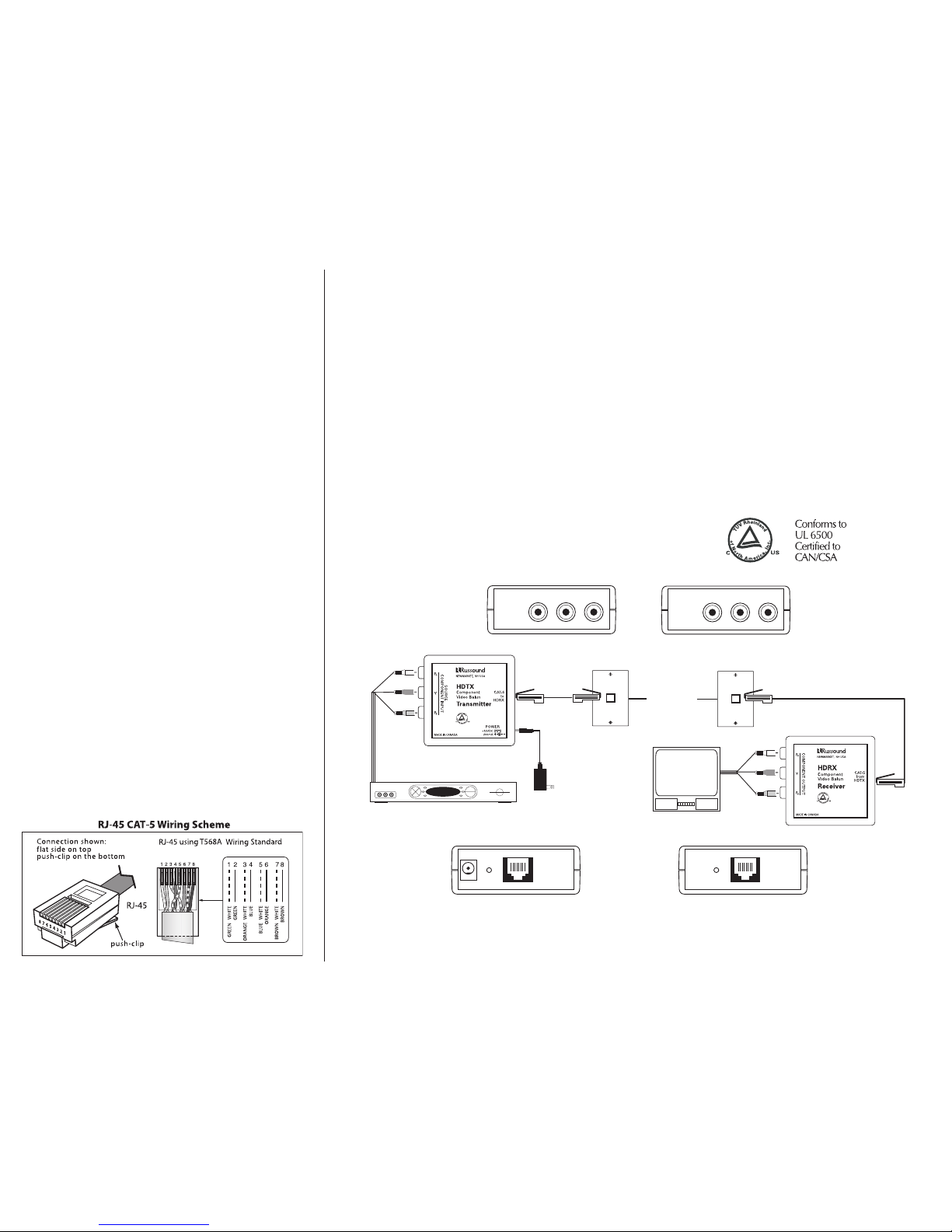
For the CAT-5 connection, use a CAT-5 patch cable with RJ45
connections at each end, using the T568A wire configuration.
Run the patch cable from the HDTX to the wall plate.
Run CAT-5 cable from the back of the wall plate to the back
of the wall plate located near the remote display.
UTP
Up to 1000'
(CAT-5)
RCA component video cable
RJ-45
HDTX connections
CAT-5 RJ45
12VDC
power
supply
HDTX
RJ-45
CAT-5 patch cable
002
HDRX connections
P
B Y PR
Blue Green Red
RJ-45
CAT-5
patch
cable
Satellite receiver
Television
RJ45 wall plate
HDRX
CAT-5 RJ45
P
B Y PR
Blue Green Red
RCA component
video cable
846C
12VDC
power
supply
///
/
SPECIFICATIONS
Dimensions: (Transmitter and Receiver)
2.6" W x 1.1" H x 1.1" D
Transmitter Inputs/ 3 RCA (Red-P
R, Green-Y, Blue-PB
Receiver Outputs:
Transmitter Output/ 1 RJ45 8-position modular
Receiver Input: connector T568A format
Cable: CAT-5
Cable distance: 500 ft point to point
Video format: Component video up to 1080i
Video bandwidth: Transmitter and Receiver
450MHz @ -3db
Video signal: Transmitter and Receiver
0.5V to 2V component
Operating voltage: 12VDC 200mA max
At the RECEIVE end:
The HDRX is located at the remote end (TV) of the system. Use a triple-wire component RCA video cable and
connect the appropriate video inputs of the source to the
HDRX unit’s Blue (PB), Green (Y), and Red (PR) outputs.
For the CAT-5 connection, use a CAT-5 patch cable with
RJ45 connections at each end, using the T568A wire
configuration. Run the patch cable from the HDRX to the
wall plate.
Once all connections are made, power can be restored
to the system and its components.
Diagram showing a typical installation with HDTX and HDRX baluns
 Loading...