

Page 1
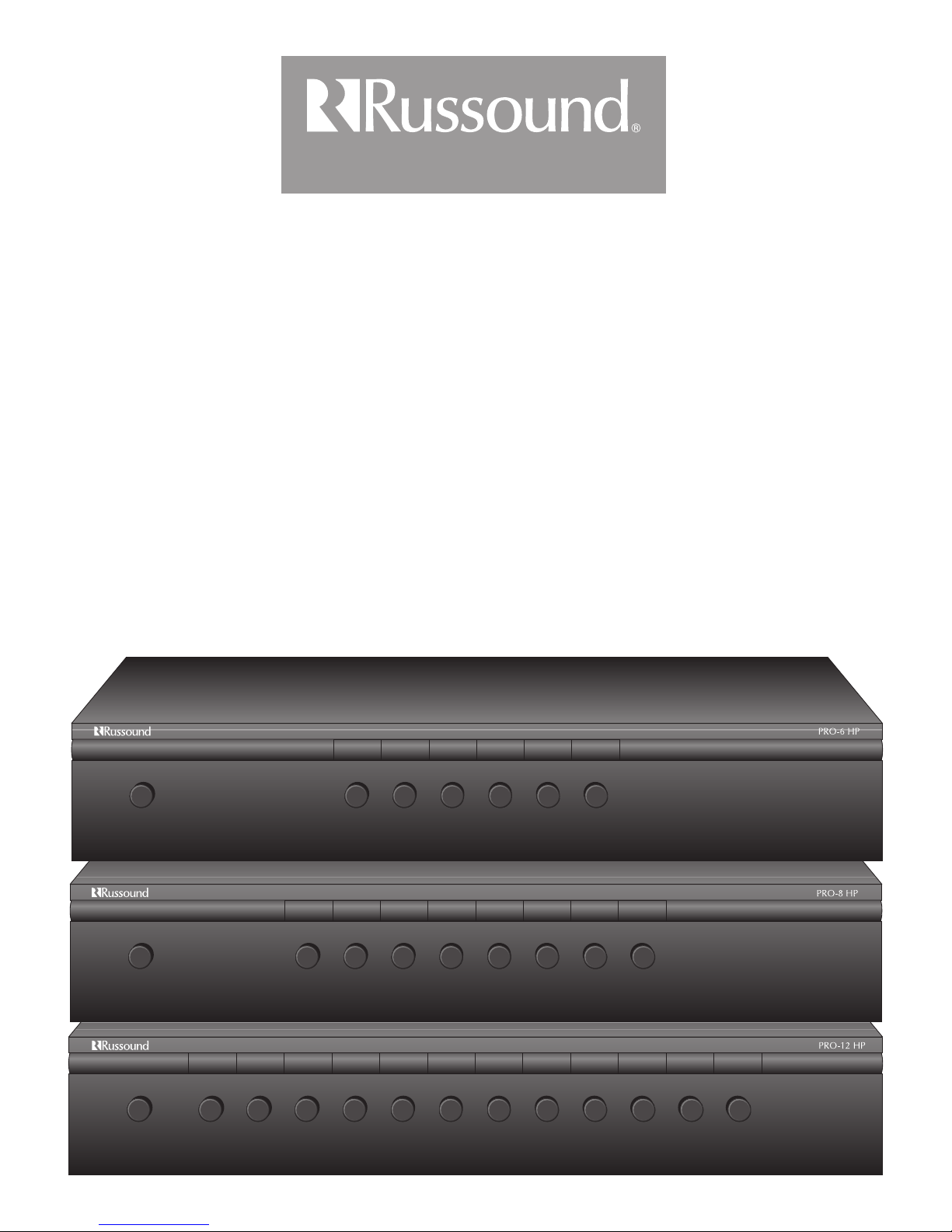
PRO Series
Instruction Manual
Dual-Source Speaker Selectors
FAMILY R OOM
1AMP A/B 2 3 4 5 6
FAMILY ROOM
1AMP A/B 2 3 4 5 6 7 8
FOYER
FAMILY ROOM
1AMP A/B 23456789101112
MASTER BATH
MASTER BEDTHEATER ROOM
BEDROOM 1 BEDROOM 2 BEDROOM 3 BEDROOM 4 BEDROOM 5 BEDROOM 6
OFFICE
GUEST BATHMASTER BATH GUEST BEDMASTER BEDTHEATER ROOM
GUEST BATHMASTER BATH GUEST BEDMASTER BEDTHEATER ROOMFOYER OFFICE
Page 2

1. Description
The PRO series speaker selectors are highly efficient dual-source, impedance-matching selectors. These high-quality speaker selectors
are designed for use with either 4 Ohm or 8 Ohm amplifiers and 4 Ohm to 8 Ohm speakers.
The PRO speaker selectors are equipped with a low-frequency protection circuit to reduce subsonic signals. This allows high power
operation without amplifier shutdown. The PRO units employ audiophile-grade impedance matching autoformers to maintain a safe
operating load at the amplifier while distributing maximum power through the system. Autoformers are very efficient because of the
small loss incurred as a result of heat dissipation. The series is equipped with a back panel rotary switch, which is used to set the appropriate impedance based on the number of pairs of speakers connected. This switch selects the proper taps of the autoformers, allowing
all of the amplifier’s power to be delivered to the speakers.
The PRO speaker selectors can be connected to one or two amplifiers. A front panel button allows switching between the two amplifiers for all speakers connected to the unit.
2. Connections
The PRO series have removable modular snap connectors that provide color-coded wire terminations without the need for set-screws.
Strip about 3/8” (0.95 cm) of insulation from the ends of all wires to be connected. If necessary, twist the exposed conductor to insure
that no loose strands exist. Remove the AMP A connector by firmly pulling it out of its 4-pole connector. Lift the wire locking lever on
connector. Insert the wires from amplifier A output, being careful to observe the polarity, then lower the lever with a “snap.” In the same
way, connect the amplifier B output to the AMP B connector. Follow the same procedure to connect each pair of speakers to the appropriate SPEAKER connector, observing proper channel and polarity. If external volume controls are used, connect speaker wire from the
appropriate speaker connector on the PRO to the volume control input. Speaker connections can support multiple speaker pairs wired
in parallel or series, provided their combined impedance is a minimum of 4 ohms.
3. Operation
To ensure safe operation of the amplifier, an impedance level must first be selected using the rotary switch labeled SPEAKER PAIRS
located on the rear of the unit. This switch should be set to the total number of speaker pairs being connected to the unit. Set the switch
based on the following conditions:
• If the amplifier and the speakers are both 4 ohms, set the rotary switch to the number of pairs of speakers connected to the PRO.
• If the amplifier and the speakers are both 8 ohms, set the rotary switch to the number of pairs of speakers connected to the PRO.
• If the amplifier is 8 ohms and the speakers are 4 ohms, set the rotary switch to TWICE the number of pairs of speakers connected to
the PRO.
• If the amplifier is 4 ohms and the speakers are 8 ohms, set the rotary switch to HALF the number of pairs of speakers connected to
the PRO.
After setting the proper impedance level, the speakers can be turned on and off in any combination.
To switch between the A and B amplifiers, push the AMP A / AMP B button located on the front panel.
4. Setting System Volume
It is important to properly adjust an impedance-matching system to avoid distortion or DC clipping (DC voltage will be produced from
an amplifier that is overworked or that has an improper load). These can cause an amplifier/receiver to go into protection, and can
cause autoformers on volume controls to heat up, damaging system components. To set up the system, the amplifier/receiver volume
should be at its lowest setting, and the in-wall/selector volume control should be at the highest setting. Slowly adjust the
amplifier/receiver volume to a level that is acceptable for the amplifier to produce without clipping.
2
Page 3

3
Speakers
WHITE -- L+ (left channel positive)
GREEN -- L- (left channel negative)
BLACK -- R- (right channel negative)
RED -- R+ (right channel positive)
Connection Diagram for Russound PRO-HP Speaker Selectors (Not to scale)
Modular Snap Connector
Wiring Order
IN
Optional ALTx-2sc
impedance-matching
volume controls
IN
PRO-6 HP NEWMARKET, NH USA
PR-6 HP
(back)
Amplifier
Page 4

5 Forbes Rd. Newmarket, NH 03857
Tel 603.659.5170 • Fax 603.659.5388
e-mail: tech@russound.com
5. Specifications
Power: 100 watts per channel RMS continuous
200 watts per channel average
300 watts per channel peak
Volume Control: 42 dB attenuation, 12 positions
Impedance Matching: High-efficiency impedance-matching autoformers
Low-Frequency Protection: Bi-polar capacitor circuit
Wire Size: up to 14 gauge wire
Dimensions: 17" W x 2.875" H x 8.25" D (43.2 x 7.3 x 21 cm)
Weight: PRO-6 7.52 lbs. (3.4 kg)
PRO-8 7.75 lbs. (3.49 kg)
PRO-12 7.995 lbs. (3.58 kg)
6. Optional Accessories
Volume Controls - ALTx Series, LPTx Series, and WALTx-2 for outdoor applications
7. Warranty
The Russound PRO Series is fully guaranteed for Ten (10) years from the date of purchase against all defects in materials and workman-
ship. During this period, Russound will replace any defective parts and correct any defect in workmanship without charge for either
parts or labor. For this warranty to apply, the unit must be installed and used according to its written instructions. If service is necessary,
it must be performed by Russound. The unit must be returned to Russound at the owner’s expense and with prior written permission.
Accidental damage and shipping damage are not considered defects under the terms of the warranty. Russound assumes no responsibility for defects resulting from abuse or servicing performed by an agency or person not specifically authorized in writing by Russound.
Damage to or destruction of components due to improper use voids the warranty. In these cases, the repair will be made at the owner’s
expense. To return for repairs, the unit must be shipped to Russound at the owner’s expense, along with a note explaining the nature of
the service required. Be sure to pack in a corrugated container with at least 3 inches of resilient material to protect the unit from damage
in transit.
Russound sells product only through authorized Dealers and Distributors to ensure that customers obtain proper support and service.
Any Russound product purchased from an unauthorized dealer or other source, including retailers, mail order sellers and online sellers
will not be honored or serviced under existing Russound warranty policy. Any sale of products by an unauthorized source or other manner not authorized by Russound shall void the warranty on the applicable product.
28-0009 Rev. 4 04/07/06
Russound is not responsible for typographical errors or omissions.
All trademarks are the property of their respective owners.
 Loading...