

Page 1
PR-4Zi
4-Zone, 6-Source
Audio/Video Preamplifier
INSTRUCTION MANUAL
Page 2
Important Safeguards
WARNING: TO REDUCE THE RISK OF FIRE OR ELECTRIC SHOCK,
DO NOT EXPOSE THIS APPLIANCE TO RAIN OR MOISTURE.
CAUTION: TO REDUCE THE RISK OF ELECTRIC SHOCK, DO NOT
REMOVE COVER. NO USER - SERVICEABLE PARTS INSIDE.
REFER SERVICING TO QUALIFIED SERVICE PERSONNEL.
The lightning flash with arrowhead symbol, within an equilateral
triangle, is intended to alert the user to the presence of uninsulated
“dangerous voltage” within the product’s enclosure that may be of
sufficient magnitude to constitute a risk of electric shock to persons.
The exclamation point within an equilateral triangle is intended to
alert the user to the presence of important operating and maintenance (servicing) instructions in the literature accompanying the
appliance.
POWER CORD NOTICE FOR INTERNATIONAL OPERATION
For 230V, 50Hz operation please select the power cord for your
area. Select the plug for your area at one end and a IEC320 connector at the other. It is not necessary to make any other
changes. If you have any questions please call Russound Inc. at
1-800-638-8055 or 603-659-5170
Safety Instructions:
1. Read Instructions - All the safety and operating instructions should be
read before the appliance is operated.
2. Retain Instructions - The safety and operating instructions should be
retained for future reference.
3. Heed Warnings - All warnings on the appliance in the operating instructions should be adhered to.
4. Follow Instructions - All operating and user instructions
should be followed.
5. Water and Moisture - The appliance should not be
used near water; for example, near a bathtub, washbowl, kitchen sink, laundry tub, in a wet basement,
or near a swimming pool.
6. Carts and Stands - The appliance should be used only
with a cart or stand that is recommended by the manufacturer. An
appliance and cart combination should be moved with care. Quick
stops, excessive force and uneven surfaces may cause the appliance
and cart combination to overturn.
7. Wall or ceiling Mounting - The appliance should be mounted to a wall
or ceiling only as recommended by the manufacturer.
8. Ventilation - The appliance should be situated so that its location or
position does not interfere with its proper ventilation. For example, the
appliance should not be situated on a bed, sofa, rug, or similar surface
that may block the ventilation openings, or placed in a built-in installation, such as a bookcase or cabinet that may impede the flow of air
through the ventilation openings.
9. Heat - The appliance should be situated away from heat sources such
as radiators, heat registers, stoves, or other appliances (including
amplifiers) that produce heat.
10.Power Sources - The appliance should be connected to a power supply
only of the type described in the operating instructions or as marked on
the appliance.
11.Grounding or Polarization - Precaution should be taken so that the
grounding or polarization means of an appliance is not defeated.
12.Power Cord Protection - Power supply cords should be routed so that
they are not likely to be walked on or pinched by items placed upon or
against them, paying particular attention to cords at plugs, receptacles,
and the point where they exit from the appliance.
13.Cleaning - The appliance should be cleaned only as recommended by
the manufacturer.
14.Non-use Periods - The power cord of the appliance should be
unplugged from the outlet when left unused for a long period of time.
15.Object and Liquid Entry - Care should be taken so that objects do not
fall and liquids are not spilled into the enclosure through the openings.
16.Damage Requiring Service - The appliance should be serviced by qualified service personnel when:
A. The power supply cord or the plug has been damaged; or
B. Objects have fallen, liquid has been spilled into the appliance; or
C. The appliance has been exposed to rain; or
D.The appliance does not appear to operate normally; or
E. The appliance has been dropped or the enclosure is damaged.
17.Servicing - The user should not attempt to service the appliance beyond
that described in the operating instructions. All other servicing should
be referred to qualified service personnel.
Precautions:
1. Power – WARNING: BEFORE TURNING ON THE POWER FOR THE
FIRST TIME, READ THE FOLLOWING SECTION CAREFULLY.
All models are designed for use with either AC120V, 60Hz or AC240,
50Hz voltages. The unit will autoswitch to either of these voltages
2. Do Not Touch The PR-4Zi With Wet Hands – Do not handle the PR-4Zi
or power cord when your hands are wet or damp. If water or any other
liquid enters the PR-4Zi cabinet, take the PR-4Zi to a qualified service
person for inspection.
3. Location of PR-4Zi – Place the PR-4Zi in a well - ventilated location.
Take special care to provide plenty of ventilation on all sides of the PR4Zi especially when it is placed in an audio rack. If ventilation is
blocked, the PR-4Zi may overheat and malfunction. Do not expose the
PR-4Zi to direct sun light or heating units as the PR-4Zi internal components temperature may rise and shorten the life of the components.
Avoid damp and dusty places.
4. Care – From time to time you should wipe off the front and side panels
of the cabinet with a soft cloth. Do not use rough material, thinners,
alcohol or other chemical solvents or cloths since this may damage the
finish or remove the panel lettering.
2
Page 3

Product Overview . . . . . . . . . . . . . . .4
Wiring Instructions . . . . . . . . . . . . . . .4
Audio/Video Sources . . . . . . . . . . . . .4
Connecting Amplifiers . . . . . . . . . . .5-6
Common and Zone Trigger Outputs . . .6
Connecting Video Monitors . . . . . . . . .7
Source Loop Outputs . . . . . . . . . . . . .7
Creating Subzones . . . . . . . . . . . . . .8
Page Trigger Output . . . . . . . . . . . . .9
Mute Input . . . . . . . . . . . . . . . . . . . .9
Control Functions . . . . . . . . . . . . . .10
PR-4Zi Control Functions . . . . . . . . . .10
Memory Procedure . . . . . . . . . . . . .11
Preset Procedure . . . . . . . . . . . . . .11
Party Mode . . . . . . . . . . . . . . . . . . .11
Contents
Peripheral Devices . . . . . . . . . . . . .12
PCK Keypads . . . . . . . . . . . . . . . . .12
Infrared Devices . . . . . . . . . . . . . . .12
PCK Keypad Control Functions . . . . .13
Paging . . . . . . . . . . . . . . . . . . . . . .14
SPG Paging Module . . . . . . . . . . . . .14
PTM-1 Paging Module . . . . . . . . . . . .14
IR Emitters . . . . . . . . . . . . . . . . . . .15
PRC-1 Remote Control . . . . . . . . . . .16
Using the PRC-1 with the PR-4Zi . . . .16
Multiple Controllers . . . . . . . . . . . . .17
Using the RS-232 Comm. Port . . . . .18
RS-232 Commands . . . . . . . . . . . . .19
Technical Specifications . . . . . . . . . .20
Warranty & Repair . . . . . . . . . . . . . .21
3
Page 4
Product Overview
IN OUT
V
L
R
The PR-4Zi is a four-zone, six-source A/V preamplifier that offers independent control of source,
volume, and tone for each zone. In addition to
standard preamplifier controls, the PR-4Zi allows
zone settings to be stored and recalled. SYSTEM ON and SYSTEM OFF functions provide single-button, system-wide on/off control. Two
PARTY modes link all zones for synchronous
operation. Interface connections are provided for
cascading as many as four PR-4Zis. An RS-232
Wiring Instructions
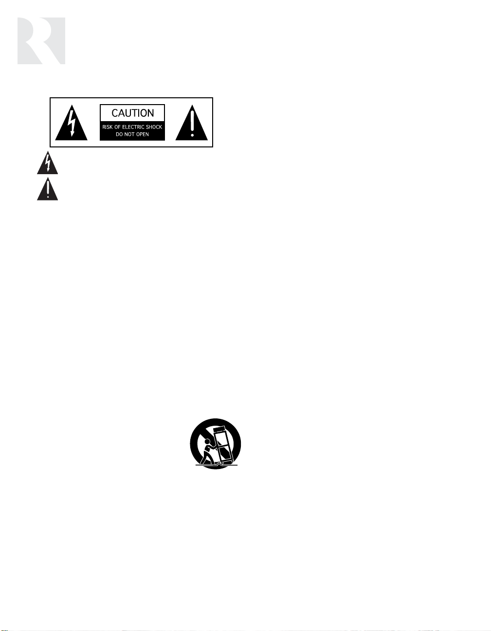
AUDIO/VIDEO SOURCES
Make line level and composite video connections
from source equipment to the PR-4Zi as shown
in Figure 1. Use high quality cables that are as
short as possible to keep signal integrity intact.
port allows the PR-4Zi to be controlled by touch
panels or other automation devices that have an
RS-232 interface. Optional Russound PCK or
PCK-IR Keypads provide easy remote operation
of the PR-4Zi. The optional Russound PRC-1
Learning Remote allows users to operate source
equipment from remote locations. Optional
Russound SPG and PTM-1 Paging Modules add
whole-house paging capabilities.
Figure 1 – A/V source connections
4
VCR (EXAMPLE OF SOURCE)
Page 5
Wiring Instructions
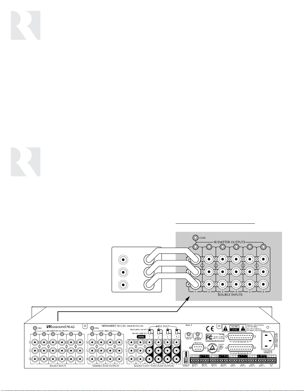
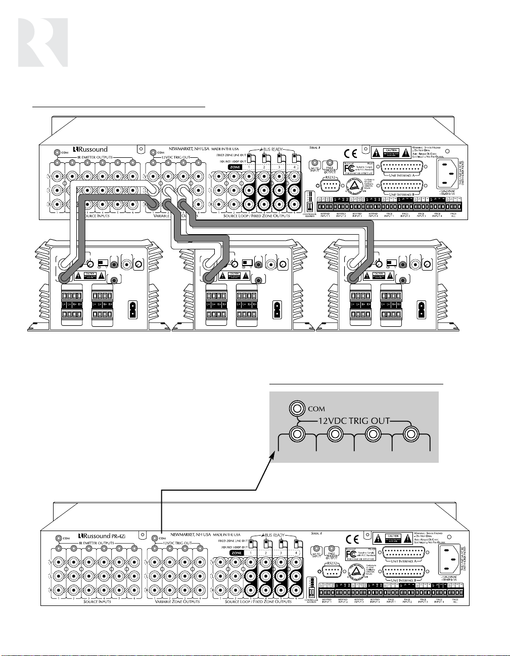
CONNECTING AMPLIFIERS
Connect the Zone Output of each PR-4Zi zone to
one line input of a multichannel amp. Figure 2
shows a connection to the Russound DPA-6.12
Twelve Channel Audio Amplifier. (Figure 2 also
shows a trigger connection, discussed on p. 6.)
Figure 2 – Multichannel amplifier connections, with tirgger connection shown to one channel
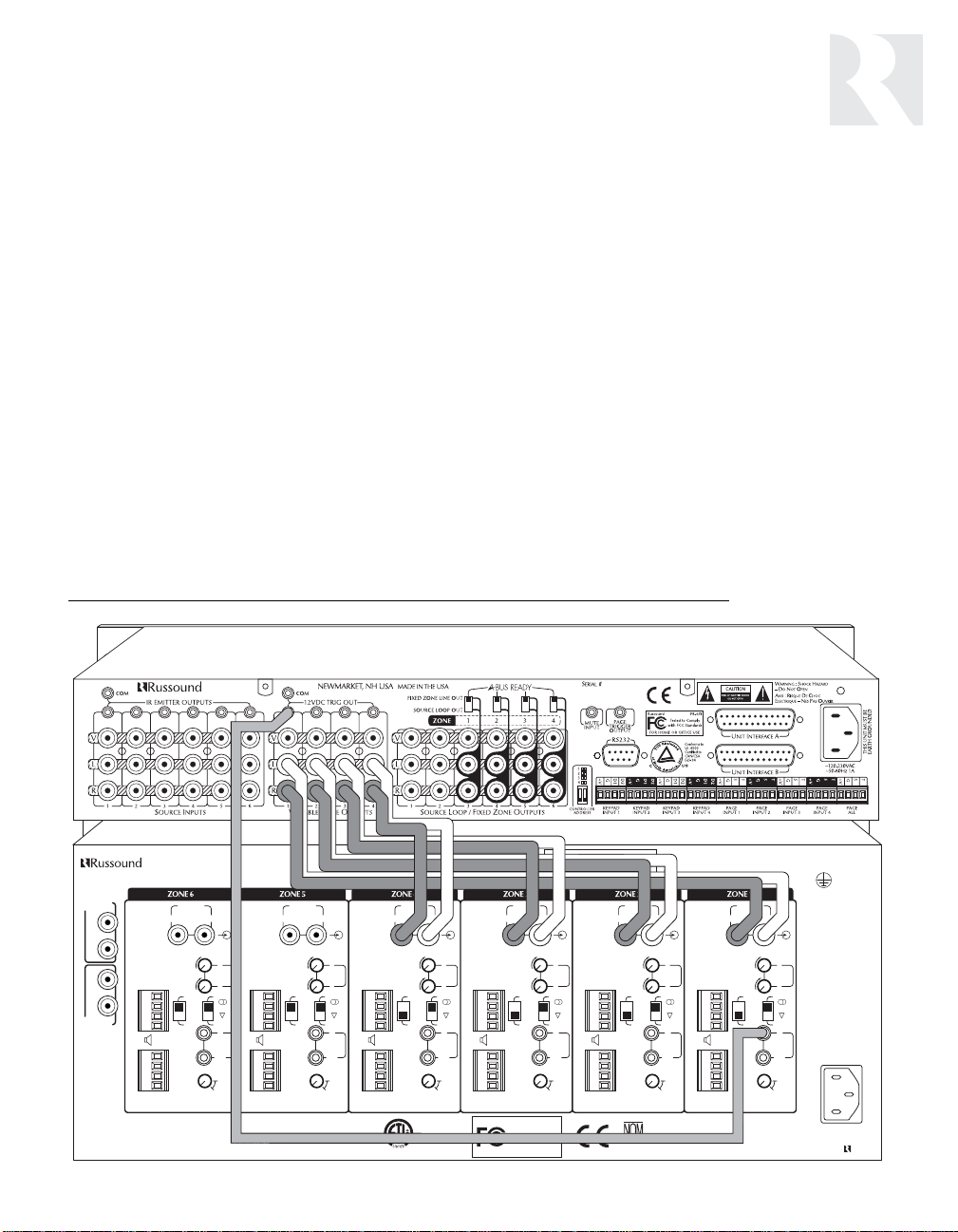
If using multiple two-channel amplifiers, such as
the Russound DPA-1.2, connect as shown in
Figure 3 (see p. 6). Use good quality audio
cables that are as short as possible to keep signal integrity intact.
MAIN BUS
INPUT
R
L
R
L
MAIN BUS
OUTPUT
PR-4Zi
WARNING : SHOCK HAZARD –
O NOT OPEN
DPA-6.12
NEWMARKET, NH USA
LINE INPUT LINE INPUT LINE INPUT LINE INPUT LINE INPUT LINE INPUT
LLLLLL
RRRRRR
LLLLLL
S
PEAKERS ASPEAKERS ASPEAKERS ASPEAKERS ASPEAKERS ASPEAKERS A
+
L
–
L
–
R
+
R
+
L
–
L
–
R
+
R
PEAKERS BSPEAKERS BSPEAKERS BSPEAKERS BSPEAKERS BSPEAKERS B
S
GAIN GAIN GAIN GAIN GAIN GAIN
RRRRRR
+
BUS BUS BUS BUS BUS BUS
LINE LINE LINE LINE LINE LINE
L
STEREO STEREO STEREO STEREO STEREO STEREO
–
L
–
R
BRGD
******
+
MONO
R
IN IN IN IN IN IN
+12V
TRIGGER
+
OUT OUT OUT OUT OUT OUT
L
100mA 100mA 100mA 100mA 100mA 100mA
–
L
333333
–
222222
444444
R
+
∞∞∞∞∞∞
111111
R
MUTING
DELAY TIME
MINIMUM LOAD IMPEDANCE:
8 OHM PER CHANNEL WHEN BOTH SPEAKER A AND B OUTPUTS ARE USED
4 OHM PER CHANNEL WHEN SPEAKER ONLY A OR B OUTPUT IS USED
* FOR BRIDGED OPERATION SEE MANUAL
DESIGNED IN THE USA
BRGD
MONO
+12V
TRIGGER
MUTING
DELAY TIME
+
L
–
L
–
R
+
R
+
L
–
L
–
R
+
R
68835
MUTING
DELAY TIME
Conforms to
UL 6500
Certified to
CSA C22.2 No1-94
MONO
+12V
TRIGGER
BRGD
+
L
–
L
–
R
+
R
+
L
–
L
–
R
+
R
Russound
Tested to Comply
with FCC Standards
FOR HOME OR OFFICE USE
MUTING
DELAY TIME
DPA-6.12
MONO
+12V
TRIGGER
+
L
–
L
–
R
BRGD
+
R
+
L
–
L
–
R
+
R
AVIS : RISQUE DE CHOC
ELECTRIQUE – NES PAS OUVRIR.
BRGD
MONO
+12V
TRIGGER
MUTING
DELAY TIME
019
D
SERIAL #
+
L
–
L
–
R
+
R
+
L
–
L
–
R
+
R
MUTING
DELAY TIME
MONO
+12V
TRIGGER
BRGD
~120VAC
~60Hz
12A
THIS UNIT MUST BE
EARTH GROUNDED
MADE IN TAIWAN
5
Page 6
Wiring Instructions
LINE INPUT
SENSING
SPEAKER A OUT
12V
TRIG
INPUT
12V TRIG
OUT 100mA
STEREO
VIDEO
INPUT
SENSING
DELAY
BRGD *
MONO
GAIN
SPEAKER B OUT
LR
1
234
5
AC
120V
60Hz
2A~
AMPLIFIED INPUT
SENSING
DEFAULT
AMPLIFIED INPUT
AVIS : RISQUE DE CHOC
ELECTRIQUE – NES PAS
OUVRIR.
* FOR BRIDGED OPERATION
SEE MANUAL
L
R
WARNING : SHOCK
HAZARD – DO NOT OPEN
PR-4Zi
Figure 3 – Tw
o-channel amplifier connections
COMMON AND ZONE TRIGGER OUTPUTS
The PR-4Zi provides four Zone-Specific and one
Common +12VDC trigger outputs (Figure 4). The
Zone-Specific triggers are turned on when the
corresponding zone is on. The Common trigger
is turned on when any zone is on. All trigger outputs are turned on during a page. Figure 2 (p. 5)
shows a Zone trigger connection to the
Russound DPA-6.12 amplifier.
Figure 4 – Common and Zone tr
igger outputs
6
Page 7
Wiring Instructions
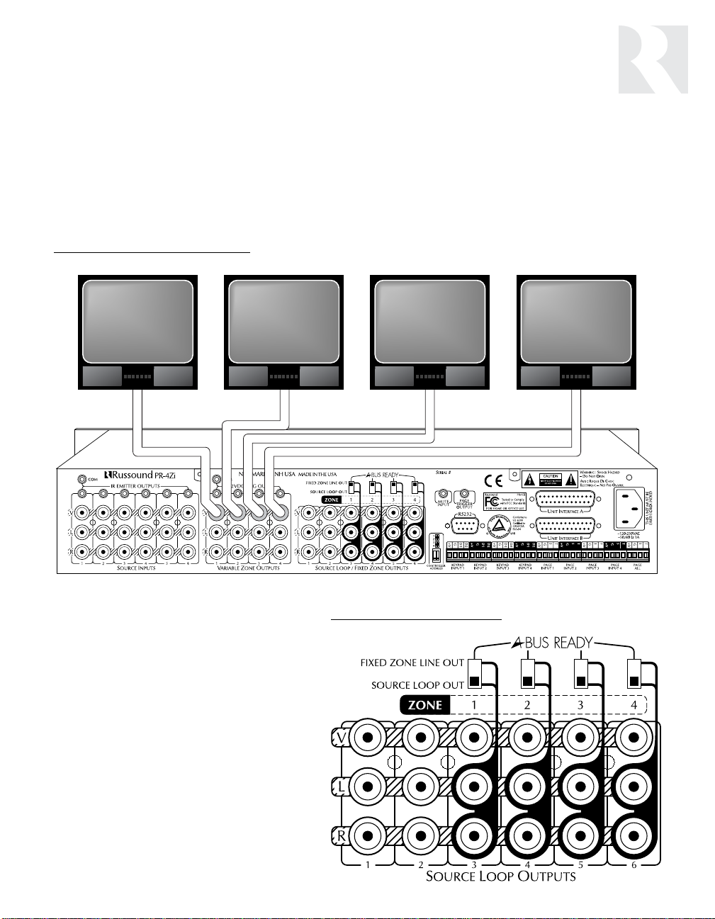
CONNECTING VIDEO MONITORS
Each PR-4Zi zone has a composite video output to allow viewing video from any of six A/V sources.
Connect monitors as shown in Figure 5 using RG6U cable with RCA type connectors. If more than two
monitors are being used in a zone, a composite video distribution amplifier is recommended. The PR4Zi video outputs are buffered and are good for up to 100’ of RG6U.
Figure 5 – Video Output connections
SOURCE LOOP OUTPUTS
The PR-4Zi has six buffered, fixed-level
audio/video outputs (Figure 6). When set
to SOURCE LOOP OUT, these output signals from the corresponding input source.
This source loop configuration allows the
PR-4Zi to pass source signals to another
component, such as a home theater controller, or to another PR-4Zi for sharing
sources in a multiple controller system.
Figure 6 – Source Loop outputs
7
Page 8
Wiring Instructions
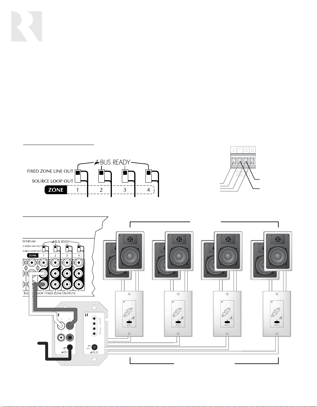
FIXED ZONE LINE OUT: CREATING SUBZONES
The PR-4Zi has six buffered, fixed-level audio/video outputs as shown previously in Figure 1 (p. 4).
When set to FIXED ZONE LINE OUT (Figure 7), the last four outputs can be used to create subzones
of each main zone. A subzone gets the same source selected for the main zone, and therefore needs
only on/off and volume control.
The lower portion of Figure 7 shows four amplified Russound A-KP2 keypads added to Zone 1. All
subzones get the same Zone 1 source, but will have independent on/off and volume control via the AKP keypad. Main zone control can be acheived by repeating IR commands in a sub-zone into the main
zones keypad input. D1 will accept IR signal for zone control.
Figure 7 – Creating subzones
PR-4ZI REAR
SIGNAL TO SUB-
TO
KEYPAD
ZONE IR OUTPUT
GND
PR-4ZI REAR
A-H4D
Connection Hub
AUDIO IN
LR
AUDIO
OUT
LR
POWER
+24V
4A
1
2
3
4
+12V
200mA
A-H4D CONNECTING BLOCK
EMITTERS
S
SPEAKERS
TATUS
A-KP2 AMPLIFIED KEYPADS
8
Page 9

TRIG OUT
TRIG
+12V DC
DB3
DB2
DB1
TRANS
POWER
DOORBELL INTERFACE
TRANS
REAR
FRONT
Wiring Instructions
PAGING TRIGGER OUTPUT
The PR-4Zi is equipped with a +12V paging trigger output (Figure 8) that switches on during a
page. This output can be used to trigger an
external amplifier, muting device, or other
peripheral associated with paging. (Paging
peripherals are discussed on page 14.)
MUTE INPUT
The PR-4Zi system mutes when a +12VDC signal
is applied to the mute input (Figure 8). This
allows connection of external paging or muting
devices.
Figure 8 – Paging trigger output
and m
ute input
12VDC POWER SUPPLY
PART# 1201A
SLEEVE (–)
DIM-1 DOORBELL
INTERFACE MODULE
TIP (+)
REAR OF
PR-4Zi
16VAC
TRANSFORMER
REAR
DOOR
FRONT
DOOR
DOORBELL
9
Page 10

Control Functions
Figure 9 – PR-4Zi control functions
1
POWER
2
12
34
ZONE SELECT
3 6 12 15
4
POWER – Controls power to entire system.
1
IR Receiver – Provides IR control for Zone 1.
2
ZONE SELECT – Selects current zone (1-4).
3
ZONE SELECT Indicators – Shows current zone.
4
SYSTEM ON & SYSTEM OFF – Turns all zones on or off. SYSTEM ON can be pre-
5
set to selectively omit zone(s).
ONE — 6 SOURCE AUDIO/VIDEO PREAMPLIFIER
4 Z
LOUDNESS PARTY
13
SOURCE LINK
SOURCE / VOL LINK
MEMORY
SYSTEM
SYSTEM
9
1
8
12
ON
ON/OFF
OFF
SOURCE
23456
34
BASS TREBLE
10
5 11 14
7
16
VOLUME
PRESET
PR-4Zi
10
ON/OFF – On/off control for current zone.
6
ON/OFF Indicators – On/off status of current zone.
7
Source Select – Changes source for current zone.
8
Source Indicators – Shows selected source for current zone.
9
BASS & TREBLE Controls – Adjusts BASS and TREBLE (▲/▼) for
10
current zone. Bass & treble: 12 steps each, 2dB per step (-12dB to +12dB).
11
LOUDNESS – Selects LOUDNESS on/off for current zone. Loudness
selectively boosts bass & treble output at low volumes.
12
PARTY – Selects from 2 PARTY modes (SOURCE LINK or SOURCE/VOL LINK).
13
PARTY Indicators – Shows PARTY mode used.
14
MEMORY – Initiates MEMORY mode for current zone.
15
PRESET – Recalls stored settings for current zone.
16
VOLUME – Controls VOLUME for current zone. Volume: 40 steps,
2dB per step (-80dB to 0dB).
Page 11

Refer to Figure 9 at left for the following procedures.
Control Functions
MEMORY PROCEDURE
MEMORY allows for permanent storage of zone
settings. Source, volume level, bass level, treble
level, loudness, paging volume, and "SYSTEM
ON disable" settings can be stored. Once
stored, these settings can be accessed by
pressing PRESET.
To set MEMORY for a single zone:
1. Select a zone using the ZONE SELECT.
2. Adjust zone as desired.
3. Press MEMORY. The MEMORY indicator will
light.
4. To store VOLUME, BASS, and TREBLE levels,
press the ▲ (up) button for the correspon-
ding function.
5. To store current input source, press any
button.
6. To store loudness setting, press LOUDNESS.
7. To prevent the zone from turning on when All
On is activated, press SYSTEM ON.
8. To preset paging volume, press VOLUME ▼
(down)
9. To exit, press MEMORY again. The MEMORY
indicator should no longer be illuminated.
To clear MEMORY for a single
1. Select a zone using ZONE SELECT.
2. Press MEMORY followed by PRESET.
3. Press MEMORY again to exit.
To clear MEMORY for all
1. Press MEMORY followed by SYSTEM OFF.
PRESET PROCEDURE
PRESET recalls settings for the current zone previously stored in memory. A preset can be
recalled at the PR-4Zi front panel, on a PCK(IR)
keypad, or via the PRC-1 remote control.
zone:
zones:
source
1. Select a zone using ZONE SELECT.
2. Press PRESET.
Pressing PRESET on a PCK keypad or PRC-1
remote control will recall the settings for that
local zone.
PARTY MODE
Two PARTY modes allow synchronous operation
of all zones.
Source Link mode. Activated upon pressing
PARTY once. Source settings are linked for all
zones. Any changes to source selection at the
PR-4Zi front panel will be made simultaneously in
all zones. However, zone volumes can be adjusted independently.
Source Link mode procedure:
1. Set Zone 1 volume and source as desired for
the entire system. Turn on each zone you
want to include for PARTY mode.
2. Press PARTY once
tor will light and the settings made for Zone 1
will be reflected in all other zones currently
turned on.
Source/Volume Link mode. Activated upon
pressing PARTY twice. Source and volume settings are linked for all zones. Any changes to
source selection or volume in one zone will be
made simultaneously in all others.
Source/Volume Link mode procedure:
1. Repeat Step 1 above.
2. Press PARTY twice
indicator will light and the settings made for
Zone 1 will be reflected in all other zones currently turned on.
. The SOURCE LINK indica-
. The SOURCE/VOL LINK
11
Page 12

Peripheral Devices
D2
D1
GND
V+
4 CONDUCTOR
2 TWISTED PAIR WIRE
WITH SHEILD
ST IR GND V+
1 PAIR TWISTED WIRE
WITH SHIELD
CONNECT SHIELD
TO GROUND
PCK(IR) KEYPADS
Each of the PR-4Zi’s zones can be remotely
operated by a keypad or IR device. There are
four keypad ports on the rear panel. Each port
accommodates as many as four Russound
PCK(IR) keypads (4 per zone). Wire the PCK(IR)
keypads to the PR-4Zi keypad input as shown
below in Figure 10 using 22-24 AWG shielded 2
twisted pair wire.
Figure 10 – PCK(IR) wiring
PR-4Zi BACK
IR DEVICES
The keypad ports are also compatible with
infrared devices such as Russound 858, 1257,
1258, and 844 IR receivers.
Wire IR devices as shown in Figure 11 using 2224 AWG 1 pair twisted wire with shield.
Figure 11 – IR de
PR-4Zi BACK
vice wiring
12
858 IR
RECEIVER
PCK(IR) KEYPAD
Page 13

PCK(IR) KEYPAD CONTROL FUNCTIONS
Peripheral Devices
Infrared Receiver – Receives IR commands
1
from Russound PRC-1 remote or a source
component’s remote. (PCK IR only)
2
SYSTEM ON – Turns all zones on.
NOTE: The system on button will also
flash to confirm IR reception.
SYSTEM OFF – Turns all zones off.
3
ZONE ON/OFF – Turns zone on/off.
4
5
PRESET – Recalls stored zone settings.
Figure 12 – PCK(IR) z
8
7
6
LOUD – Selects and indicates loudness on/off.
6
Source Select – Selects and shows input source.
7
SELECT – Selects function (bass, treble,
8
volume) to be adjusted with ▼/▲ buttons.
9
BASS / TREBLE / VOLUME Indicators –
Shows function selected for adjustment.
10
▼/▲ Buttons – Adjusts bass, treble, and
volume.
one control functions
TREBLE VOLUMEBASS
SELECT
CD TAPETUNER
VID2 DVDVID1
ZONE
PRESETLOUD
ON/OFF
9
10
4
5
SYSTEM
2
ON
PR-4Z SYSTEM CONTROLLER
SYSTEM
OFF
3
1
13
Page 14

Peripheral Devices
DSC/DAN KEYPADS
Once the PCK(IR) keypads have been wired, connect the DSC keypad’s 16-pin header to the 16pin receptacle on the side of the main keypad
(see Figure 1a and 1b). Be sure to keep the correct pin alignment. If you are using a DAN keypad with the system, connect it to the input
receptacle on the side of the DSC keypad.
Figure 13 – DSC and DAN docking
PCK-IR OR PCK DSC DAN
TREBLE VOLUMEBASS
SELECT
CD TAPETUNER
VID2 DVDVID1
ZONE
ON/OFF
SYSTEM
ON
PR-4Z SYSTEM CONTROLLER
SYSTEM
PRESETLOUD
OFF
SEEK
MODE
PRG CLR RST
SELECT
SCAN
DIRECT SOURCE CONTROL
IR IN PRG STO ERR
2
PRG CLR RST
564
897
0
DIRECT ACCESS
NUMERIC SOURCE KEYPAD
31
ENTER
OPERATING THE DSC/DAN KEYPADS
Select the source that you wish to control
1
on the main keypad (this will also select the
source for listening).
Press the command key(s) on the DSC or
2
DAN which have been programmed with the
commands that you wish to execute.
The Program indicator will flash as the
3
command is outputted. If the Program
indicator does not flash when the
command key is pressed, the
command was not stored properly.
IR IN PRG STO ERR
14
Page 15

IKP-1 INFRARED KEYPAD PROGRAMMER
The IKP-1 is a programmer used to simplify and
speed up the IR programming for the DAN and
DSC IR learning keypads. Learning keypads that
can be used with the programmer have a plug
located at the front left. Refer to IKP-1
Instruction Manual for complete instructions.
Figure 14 – Multiple Progamming with IKP-1
DSC OR DAN
KEYPAD
IR IN PRG STO ERR
IR IN PRG STO ERR
IR IN PRG STO ERR
KEYPAD PORT KEYPAD PORT
PRG CLR RST
F
NEWMARKET, NH U.S.A.
D
OWNLOAD
ROM KEYPAD
INFRARED LEARNING
KEYPAD PROGRAMMER
IKP-1
TO K
EYPAD
E
RROR
DAN DSC
D
ATA
T
RANSFER
IKP-1
T
U
PLOAD
O KEYPAD
PRG CLR RST
KEYPAD PORTKEYPAD PORT
DESIGNED IN USA MADE IN KOREA
PRG CLR RST
Peripheral Devices
IR IN PRG STO ERR
PRG CLR RST
POWER
12VDC 100mA
12VDC Power Supply
15
Page 16

Peripheral Devices
PR-4Zi PAGE INPUT
4 CONDUCTOR
TWISTED
PAIR SHEILD
SENSITIVITY
ADJUSTMENT
TGR
SIG
GND
12+
TGR
SIG
GND
12+
LESSMORE
CP 4.6 PAGE INPUT
TSGV
PTM-1 PAGE TRIGGER MODULE
ON TGR
IN
OUT
OUT
PAGE
PAGING
The PR-4Zi has five paging inputs. The four
Zone-Specific PAGE INPUTS allow for paging to
all zones except the zone where the page originates. The PAGE ALL input will allow paging to
all zones. A page turns on all zones to their
respective preset paging volume (see Memory
Procedure, p. 11). All devices triggered by any
of the trigger outputs will also be turned on.
Russound offers many paging options to suit
most applications. See the Tech and FAQ sections at www
.russound.com or call Russound for
additional information.
Figure 15 – SPG wir
ing instructions
SPG PAGING MODULE
The Russound SPG provides "push-to-talk" operation. Use 22-24 AWG twisted pair shielded wire
to connect the SPG to the PR-4Zi page input as
shown in Figure 15.
PTM-1 PAGING MODULE
The Russound PTM-1 is a signal-sensing paging
adapter for the PR-4Zi that accepts the page
output or other line-level audio output from telephone paging systems, paging preamplifiers,
switch-triggered voice/sound recording devices,
etc. Use 22-24 AWG twisted pair shielded wire
to connect the PTM-1 to the PR-4Zi page input
as shown in Figure 16.
Figure 16 – PTM-1 wiring configuration
SPG PAGING KEYPAD
16
TGR T
GND G
SIG S
12+ +V
Page 17

Peripheral Devices
TIP
SLEEVE
1/8" (MONO)
PHONE PLUG
STRIPE WIRE
IS SIGNAL
(WIRES TO TIP)
RUSSOUND #857
CONNECTING BLOCK
123456
IR R
ECEIVER
I
N
IR C
OMMON
I
N
IR C
ONFIRM
+
12VDC
GND
STATUS
SIGNAL
E
MITTERS
S
TATUS
+
12VDC
P
OWER
+
12VDC
DESIGNED IN USA MADE IN KOREA
857 I
NFRARED
C
ONNECTING
B
LOCK
RUSSOUND #845.1 MICRO EMITTERS
TO IR CONTROLLED EQUIPMENT
845.1 MICRO EMITTERS TO
IR RECEIVER WINDOW
OF SOURCE EQUIPMENT
SOURCE 2
SOURCE 1
IR EMITTERS
The PR-4Zi has seven IR outputs:
Source 1–6 and Common. Source
1–6 outputs are source-specific and
provide IR signals only to the
selected source; the Common output provides IR signals to all
sources.
Source-specific IR outputs (Figure
17) are useful when a system has
two or more of the same model
source component, allowing you to
target the IR commands to each
individual component.
To connect multiple emitters to the
Common IR output, use the
Russound 857 connecting block
and a 1/8-inch (3.5mm), 2-conductor (mono) phone plug as shown in
Figure 18. Connect common (COM)
IR output to “IR INPUT” on the 857
connecting block.
Figure 17 – Source-specific infrared outputs
Figure 18 – Common infr
ared output
17
Page 18

Peripheral Devices
PRC -1 REMOTE CONTROL
The Russound PRC-1 remote control is preprogrammed to operate more than 1,000 audio and
video components, including the PR-4Zi. Set it up by
simply punching in a three-digit code that matches
your equipment. The PRC-1 also has the ability to
learn new functions, allowing you to customize it and
update it as you add new equipment. The PRC-1
operates up to eight different audio and video components in a home entertainment system.
The PRC-1 controls only the local zone you are in.
USING THE PRC -1 WITH THE PR-4Zi
To activate the PRC-1 for use with the PR-4Zi:
1. Turn on the PR-4Zi using its fr
ont-panel switch.
2. On the PRC-1, press the AUX and MUTE buttons
simultaneously, then release.
3. Point the PRC-1 toward the PR-4Zi and press the
three-digit code 0-8-1.
4. On the PRC-1, press the AUX button again to
store the code.
5. Henceforth, pressing the AUX button on the PRC1 accesses all the preprogrammed codes for the
PR-4Zi.
All the functions available on the PCK keypad are
also available on the PRC-1. NOTE: The PRC-1 can
turn on the local zone by pressing the POWER button, and turn off that zone by pressing the MUTE
button.
Figure 19 – PRC-1 Preprogrammed
& Learning Remote Control
AUXDVDCDAUD
CBLVCRTVSAT
POWER
VOL CH
MUTE
T/V
GUIDE
EXIT
123
TUNER CD TAPE
456
VID 1 VID 2 DVD
789
ALL ON
+10
TUNER
TAPE CENTER
M1 M2 M3 M4
SYSTEM
ON
PAUSE
R
SEL
E
PLAY
W
STOP
ALL OFF PRESET
0 ENTER ALT
PIP
Ld
REAR CENTER DELAY
BASS TREBLE
LIGHT
SHIFT
F
•
F
SYSTEM
MENU
FAV
SLEEP
INFO
PRO.L
NEXT
3.CH
TEST
SURR
OFF
PRE.
CH
18
PROGRAMMABLE REMOTE CONTROL
PRC-1
Page 19

DB-25 MALE / MALE CONNECTOR
INSTALLING MULTIPLE PR-4Zi CONTROLLERS
As many as four PR-4Zis can be cascaded via
DB-25 connectors. Cascading links multizone
functions such as SYSTEM ON, SYSTEM OFF,
PAGING, and PARTY mode so that these functions can be used system-wide. (In order to
share sour
ces among linked PR-4Zis you must
connect the Source Loop outputs of the parent
controller to the A/V inputs of controller #2, and
so on.)
Figure 20 – Interface cable connections for multiple PR-4Zi’s
Multiple Controllers
The DB-25 cable needs to be a straight passthrough or RS232C rated with a male connector
at both ends.
ie. Radio Shack Part # 26-233
19
Page 20

Using the RS-232 Communications Port
The PR-4Zi is equipped with one DB-9 connector for RS-232 communication with AMX™, Crestron™,
and similar automation systems. All PR-4Zi control functions (except for paging) can be accessed
through the RS-232 port. The PR-4Zi will also send confirmation data to the controlling system. These
updates will be performed when any change has been executed or when the “SEND ZONE STATUS
INFORMATION” request is sent to the PR-4Zi.
CONTROLLER ADDRESS SWITCH SETTINGS
Up to 16 zones can be controlled from a single RS-232
port by setting the Controller Address Switch located left
of the DB-9 connector (Figure 21).
Controller #1 (Zones 1-4)
Controller #2 (Zones 5-8)
Controller #3 (Zones 9-12)
Controller #4 (Zones 13-16)
RS-232 COMMAND PROTOCOLS
Commands are sent from RS-232 controlling device to the PR-4Zi as 8 ASCII bytes. The first two
ASCII bytes “RU” establish that the command is a Russound command for zone commands only. The
next 3 bytes “Z01” establish the zone to be controlled. The last 3 bytes “ZON” comprise the command sent to that zone. Commands are sent as ASCII values, asynchronous, 4800 bps, 8 data bits, 1
start bit, 1 stop bit, no parity.
Figure 21 –_Controller Address Switch
PR-4Zi FEEDBACK BYTES TO CONTROLLING DEVICE
Feedback bytes will be sent immediately after a command is given to the PR-4Zi. The first decimal
byte “101” (Zone 1) establishes which zone the update is for. The second decimal byte “40” (min. volume has been set) is the update data. Each update starts with the zone number update value (101 -
116) and is followed by a control update value (see list on next page). Commands are sent as decimal values, asynchronous, 4800 bps, 8 data bits, 1 start bit, 1 stop bit, no parity.
20
Page 21

RS-232 Commands & Update Values
TI-ZONE COMMANDS
MUL
RUALZOZN system on
RUALZOZF system off
RUSORCLC party mode (source link)
RUSORCLN party mode (source/volume link)
ZONE COMMANDS
Zone number (XX) can be between 01 and 16. Use the addressing switch
(Figure 19) to set zone numbers (01-04), (05-08), (09-12), (13-16)
RUZXXZON zone on
RUZXXZOF zone off
RUZXXVLU volume up
RUZXXVLD volume down
RUZXXBSU bass up
RUZXXBSD bass down
RUZXXTBU treble up
RUZXXTBD treble down
RUZXXSR1 source input 1
RUZXXVLP volume level set followed by decimal value 40 (min) <-> 0 (max)
RUZXXBSP bass level set followed by decimal value 0 (min) <-> 12 (max)
RUZXXTBP trebel level set followed by decimal value 0 (min) <-> 12 (max)
RUZXXSRD send zone status information
ZONE NUMBER UPDA
101 update to be sent for zone 1
102 update to be sent for zone 2
103 update to be sent for zone 3
104 update to be sent for zone 4
105 update to be sent for zone 5
106 update to be sent for zone 6
107 update to be sent for zone 7
108 update to be sent for zone 8
109 update to be sent for zone 9
110 update to be sent for zone 10
111 update to be sent for zone 11
112 update to be sent for zone 12
113 update to be sent for zone 13
114 update to be sent for zone 14
115 update to be sent for zone 15
116 update to be sent for zone 16
TE VALUES
RUZXXSR2 source input 2
RUZXXSR3 source input 3
RUZXXSR4 source input 4
RUZXXSR5 source input 5
RUZXXSR6 source input 6
RUZXXPST preset
RUZXXBSF bass level flat
RUZXXTBF treble level flat
RUZXXLOD loudness toggle on/off
UPDA
TE VALUES
0 thru 40 update volume position 40 (min) <-> 0 (min)
41 source 1 selected
42 source 2 selected
43 source 3 selected
44 source 4 selected
45 source 5 selected
46 source 6 selected
50 thru 62 update treble position 0 (min) <-> 12 (max)
70 thru 82 update bass position 0 (min) <-> 12 (max)
90 zone is on
91 zone is off
92 loudness contour is on
93 loudness contour is off
94 source lock party mode selected
95 source link party mode selected
96 party mode is off
200 update to be sent to all zones
ALL OTHER UPDATE VALUES (0 <-> 255) OTHER THAN
SHOWN ABOVE ARE RESERVED FOR FUTURE USE.
21
Page 22

Technical Specifications
Frequency Response: 20 - 20kHz + 0.1 dB max.
Total Harmonic Distortion: 0.06% max.
Signal-to-Noise Ratio: 95 dB min, "A" weighted
Maximum input voltage: 4.6 VRMS, 6 Volts peak
Maximum output voltage: 8.5 VRMS, 12 Volts peak
Volume Control: 0 dB to -80 dB (40 steps)
Bass and Treble Controls: +/- 12 dB (12 steps)
Standard Features: 6 Audio / Video source inputs
4 stereo audio/video outputs
4 keypad / Infrared ports
4 Paging unit ports
5 +12V Trigger outputs (4 zone specific, 1 common)
5 Infrared transport outputs (6 source specific, 1 common)
Built-in IR receiver for zone #1
RS-232 Interface for control of up to 4 PR-4Zi from an
external control system
Unit Interface allows cascading of up to four PR-4Zi (16 zones)
Optional Features: Full function PCK keypad
Full function PCK-IR keypad w/ built-in IR receiver
DSC direct source control IR learning keypad
DAN direct access numeric IR learning keypad
In-wall SPG paging module
PTM-1 telephone paging interface module
PRC-1 programmable remote control
Power requirements: AC 110 – 240 volts, 50 - 60Hz, 1 AMP.
Dimensions: 19" W x 12" D x 3.6" H.
Weight: 12 lbs.
The PR-4Zi complies with the requirements of the standards for Audio Video Products and
Accessories (UL 1492, 1st Edition) and Radio, Television, and Electronic Apparatus (CSA C22.2 No.
1-M94).
22
Page 23

Warranty & Repair
The Russound PR-4Zi is fully guaranteed against all defects in materials and
workmanship for two (2) years from the date of purchase. During this period, Russound will replace any defective parts and correct any defect in
workmanship without charge for either parts or labor. For this warranty to
apply, the unit must be installed and used according to its written instructions. If service is necessary, it must be performed by Russound. The unit
must be returned to Russound at the owner’s expense and with prior written
permission. Accidental damage and shipping damage are not considered
defects under the terms of the warranty. Russound assumes no responsibility for defects resulting from abuse or servicing performed by an agency or
person not specifically authorized in writing by Russound. Damage to or
destruction of components due to improper use voids the warranty. In these
cases, the repair will be made at the owner’s expense. To return for repairs,
the unit must be shipped to Russound at the owner’s expense, along with a
note explaining the nature of the service required. Be sure to pack the unit
in a corrugated container with at least 3 inches of resilient material to protect the unit from damage in transit.
Before returning a unit for repair, call Russound at (603) 659-5170 for a
Return Authorization number. Write this number on the shipping label and
ship to:
Russound
5 Forbes Road
Newmarket, NH 03857
Attn: Service
23
Page 24

Russound
5 Forbes Road, Newmarket, NH 03857
tel 603.659.5170 • fax 603.659.5388
e-mail: tech@russound.com
www.russound.com
fax-on-demand: 603.659.5590 28-0105
 Loading...