

PR-4Z
SERVICE MANUAL
TREBLE VOLUMEBASS
PR-4Z SYSTEM CONTROLLER
SELECT
CD TAPETUNER
VID2 DVDVID1
ZONE
ON/OFF
PRESETLOUD
SYSTEM
OFF
SYSTEM
ON
TUNER
12
ON/OFF
ZONE SELECT
POWER
ALL
ON
ALL
OFF
BASS TREBLE
LOUDNESS PARTY
SOURCE LINK
SOURCE LOCK
MEMORY
VOLUME
PRESET
34
CD TAPE VIDEO 1VIDEO 2DVD
4 ZONE — 6 SOURCE AUDIO/VIDEO PREAMPLIFIER
PR-4Z
12
34
4-Zone / 6-Source A/V
Preamplifier / Controller
PR-4Z
Instruction Manual

2
“WARNING” “ TO REDUCE THE RISK OF FIRE OR ELECTRIC SHOCK,
DO NOT EXPOSE THIS APPLIANCE TO RAIN OR MOISTURE.”
“CAUTION” “ TO REDUCE THE RISK OF ELECTRIC SHOCK, DO NOT
REMOVE COVER. NO USER - SERVICEABLE PARTS INSIDE. REFER
SERVICING TO QUALIFIED SERVICE PERSONNEL.
The lightning flash with arrowhead symbol, within an equilateral triangle, is
intended to alert the user to the presence of uninsulated “dangerous voltage”
within the products enclosure that may be of sufficient magnitude to constitute a
risk of electric shock to persons.
The exclamation point within an equilateral triangle is intended to alert the user
to the presence of important operating and maintenance (servicing) instructions in
the literature accompanying the appliance.
POWER CORD NOTICE FOR INTERNATIONAL OPERATION-Please note that for 230V
50Hz operation please select the power cord for your area. Select the plug for
your area at one end and a IEC320 connector at the other. It is not necessary to
make any other changes. If you have any questions please call Russound Inc.
1800-638-8055 or 603-659-5170
Safety Instructions:
1. Read Instructions - All the safety and operating instructions should be read
before the appliance is operated.
2. Retain Instructions - The safety and operating instructions should be retained
for future reference.
3. Heed Warnings - All warnings on the appliance in the operating instructions
should be adhered to .
4. Follow Instructions - All operating and user instructions should be followed.
5. Water and Moisture - The appliance should not be used near water - for
example, near a bathtub, washbowl, kitchen sink, laundry tub, in a wet basement, or near a swimming pool, and the like.
6. Carts and Stands - The appliance should be used only
with a cart or stand that is recommended by the manufacturer. An appliance and cart combination should
be moved with care. Quick stops, excessive force and
uneven surfaces may cause the appliance and cart combination to overturn.
7. Wall or ceiling Mounting - The appliance should be mounted to a wall or ceiling only as recommended by the manufacturer.
8. Ventilation - The appliance should be situated so that its location or position
does not interfere with its proper ventilation. For example, the appliance
should not be situated on a bed, sofa, rug, or similar surface that may block
the ventilation openings or, placed in a built - in installation, such as a bookcase or cabinet that may impede the flow of air through the ventilation openings.
9. Heat - The appliance should be situated away from heat sources such as radiators, heat registers, stoves, or other appliances ( including amplifiers ) that produce heat.
10. Power Sources - The appliance should be connected to a power supply only of
the type described in the operating instructions or as marked on the appliance.
11. Grounding or Polarization - The precautions that should be taken so that the
grounding or polarization means of an appliance is not defeated .
12. Power - Cord Protection - Power supply cords should be routed so that they
are not likely to be walked on or pinched by items placed upon or against
them, paying particular attention to cords at plugs, receptacles, and the point
where they exit from the appliance.
13. Cleaning - The appliance should be cleaned only as recommended by the manufacturer.
14. Non-use Periods - The power cord of the appliance should be unplugged from
the outlet when left unused for a long period of time.
15. Object and Liquid Entry - Care should be taken so that objects do not fall and
liquids are not spilled into the enclosure through the openings.
16. Damage Requiring Service - The appliance should be serviced by qualified
service personnel when:
A. The power - supply cord or the plug has been damaged; or
B. Objects have fallen, liquid has been spilled into the appliance; or
C. The appliance has been exposed to rain; or
D. The appliance does not appear to operate normally; or
E. The appliance has been dropped or the enclosure is damaged.
17. Servicing - The user should not attempt to service the appliance beyond that
described in the operating instructions. All other servicing should be referred
to qualified service personnel.
Precautions:
1. Warranty Card – The serial number appears on the rear panel of this unit near
the power cord. Copy the serial number onto your warranty card and mail it
back to Russound / FMP, Inc. 5 Forbes Road Newmarket, New Hampshire
03857. Be sure to retain a copy and keep it in a safe place.
2. Power – WARNING, BEFORE TURNING ON THE POWER FOR THE FIRST TIME ,
READ THE FOLLOWING SECTION CAREFULLY. All models are designed for use
only with the power supply voltage of the region where they are sold. USA
and Canadian: AC 120c, 60Hz.
3. Voltage Label ( Rear Panel ) – A label located at the rear panel power connection indicates the AC power input for the unit. For use in the USA and Canada
the label will read AC120V, 60 Hz.
4. Do Not Touch The PR-4Z With Wet Hands. Do not handle the PR-4Z or power
cord when your hands are wet or damp. If water or any other liquid enters the
PR-4Z cabinet, take the PR-4Z to qualified service personal for inspection.
5. Location of PR-4Z Place the PR-4Z in a Well - Ventilated Location. Take special
care to provide plenty of ventilation on all sides of the PR-4Z especially when
it is placed in an audio rack. If ventilation is blocked, the PR-4Z may over heat
and malfunction. Do not expose the PR-4Z to direct sun light or heating units
as the PR-4Z internal components temperature may rise and shorten the life
of the components. Avoid damp and dusty places .
6. Care – From time to time you should wipe off the front and side panels and
the cabinet with a soft cloth. Do not use rough material, thinners, alcohol or
other chemical solvents or cloths since this may damage the finish or remove
the panel lettering.
IMPORTANT SAFEGUARDS

3
CONTENTS
Product Overview . . . . . . . . . . . . . . . . . . . . . . . . . . . . . . . .4
Wiring Instructions . . . . . . . . . . . . . . . . . . . . . . . . . . . . . .5
PR-4Z Wiring Instructions . . . . . . . . . . . . . . . . . . . . . . .5-7
Source Component Connections . . . . . . . . . . . . . . . . . .5
Amplifier Connections . . . . . . . . . . . . . . . . . . . . . . . . . .6
Video Output Connections . . . . . . . . . . . . . . . . . . . . . . .7
Video Output with RF Modulators . . . . . . . . . . . . . . . . .7
Control Features . . . . . . . . . . . . . . . . . . . . . . . . . . . . . . . .8
PR-4Z Control Features . . . . . . . . . . . . . . . . . . . . . . . . . .8-9
Zone Control Functions . . . . . . . . . . . . . . . . . . . . . . . . .8
Audio Control Functions . . . . . . . . . . . . . . . . . . . . . . . . .9
Advanced Control Functions . . . . . . . . . . . . . . . . . . . . .9
Advanced Control Function Procedures . . . . . . . . . . . . . .10
Memory Procedure . . . . . . . . . . . . . . . . . . . . . . . . . . . .10
Preset Procedure . . . . . . . . . . . . . . . . . . . . . . . . . . . . . .10
Party Mode Procedure . . . . . . . . . . . . . . . . . . . . . . . . .10
Peripheral Devices . . . . . . . . . . . . . . . . . . . . . . . . . . . . . .11
PCK Keypad Wiring . . . . . . . . . . . . . . . . . . . . . . . . . . . . . .11
Infrared Device Wiring Instructions . . . . . . . . . . . . . . . . .11
PCK Control Features . . . . . . . . . . . . . . . . . . . . . . . . . . . .12
SPG & PTM-1 Paging Modules . . . . . . . . . . . . . . . . . .13-14
PR-4Z IR Emitter Outputs . . . . . . . . . . . . . . . . . . . . . . . . .14
PRC-1 Remote Control . . . . . . . . . . . . . . . . . . . . . . . . . . .15
Multiple Controllers . . . . . . . . . . . . . . . . . . . . . . . . . . . .16
Technical Information . . . . . . . . . . . . . . . . . . . . . . . . . . .17
Warranty . . . . . . . . . . . . . . . . . . . . . . . . . . . . . . . . . . . . .18
4
PRODUCT OVERVIEW
The PR-4Z is designed to provide independent preamp-level
audio and video control for up to four areas, each having
the capability of selecting on/off, loudness, source, 1-6, as
well as adjusting volume, bass and treble. In addition to
standard preamplifier controls, the PR-4Z also provides many
sophisticated control functions to allow customization of
each zone, as well as synchronous operation of all zones. The
memory and preset functions allow the user to customize
each zone by storing volume bass and treble level, loudness
and source information, which can be accessed later simply
by pressing the preset button. The All On and All Off
functions provide single-button, system-wide on/off control.
Two party modes link together source selection and volume
for all zones for synchronous operation. Interface connections are provided for cascading up to 4 PR-4Z’s together.
Optional PCK & PCK-IR in-wall keypads with built in infrared
receivers provide easy remote operation of the PR-4Z’s internal preamplifiers. Optional DSC & DAN in-wall learning keypads allow the user to operate source equipment from
remote locations, as well. Optional SPG Keypad, DTI-1
Doorbell-Telephone Interface and PTM-1 paging modules
offer a number of different features for whole-house paging.
T
UNER
12
ON/O
FF
Z
ONE SELECT
P
OWER
A
LL
O
N
A
LL
O
FF
B
ASS
T
REBLE
L
OUDNESSPARTY
SOURCE LINK
SOURCE LOCK
M
EMORY
V
OLUME
P
RESET
34
CD T
APEVIDEO
1V
IDEO
2DVD
4 Z
ONE
— 6 S
OURCE AUDIO/VIDEO PREAMPLIFIER
PR-4Z
12
34
INPUTS
TUNER CD TAPE VID1VID2DVD 1 432
I
NPUTS OUTPUT TO ZONES
L
R
LEFT
VIDEO
RIGHT
FUSE
10A
CMN
IR
O
UT
1234
S
WITCHED
AC OUTLETS
115V~ 60Hz
1A MAX TOTAL
UNIT INTERFACE B
U
NIT INTERFACE A
AC TO AP-48
8A MAX
AC 115V~
60Hz 10A MAX
V+GD1D2 V+GD1D2 V+GD1D2 V+GD1D2 V+GST V+GST V+GST V+GST
PR-4Z
NEWMARKET, NH U.S.A.
WARNING : SHOCK HAZARD – DO NOT OPEN
AVIS : RISQUE DE CHOC ELECTRIQUE – NES PAS OUVRIR.
SERIAL #
KEYPAD 1KEYPAD 2KEYPAD 3KEYPAD 4PAGE 1PAGE 2PAGE 3PAGE 4
Conforms to
UL 1492
Certified to
CSA C22.2 #1
68835
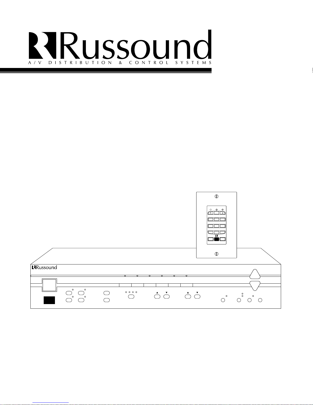
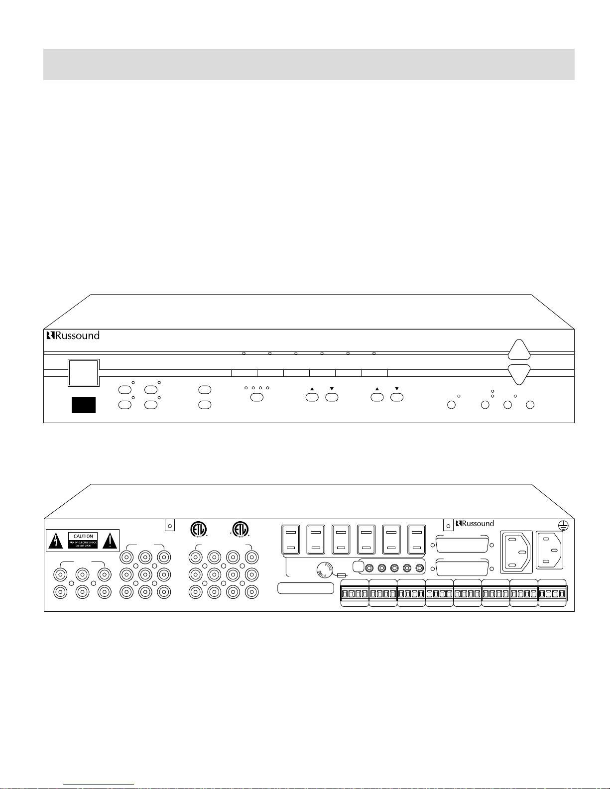
FIgure 1 – PR-4Z Front View
Figure 2 – PR-4Z Rear View
5
WIRING INSTRUCTIONS
PR-4Z WIRING INSTRUCTIONS
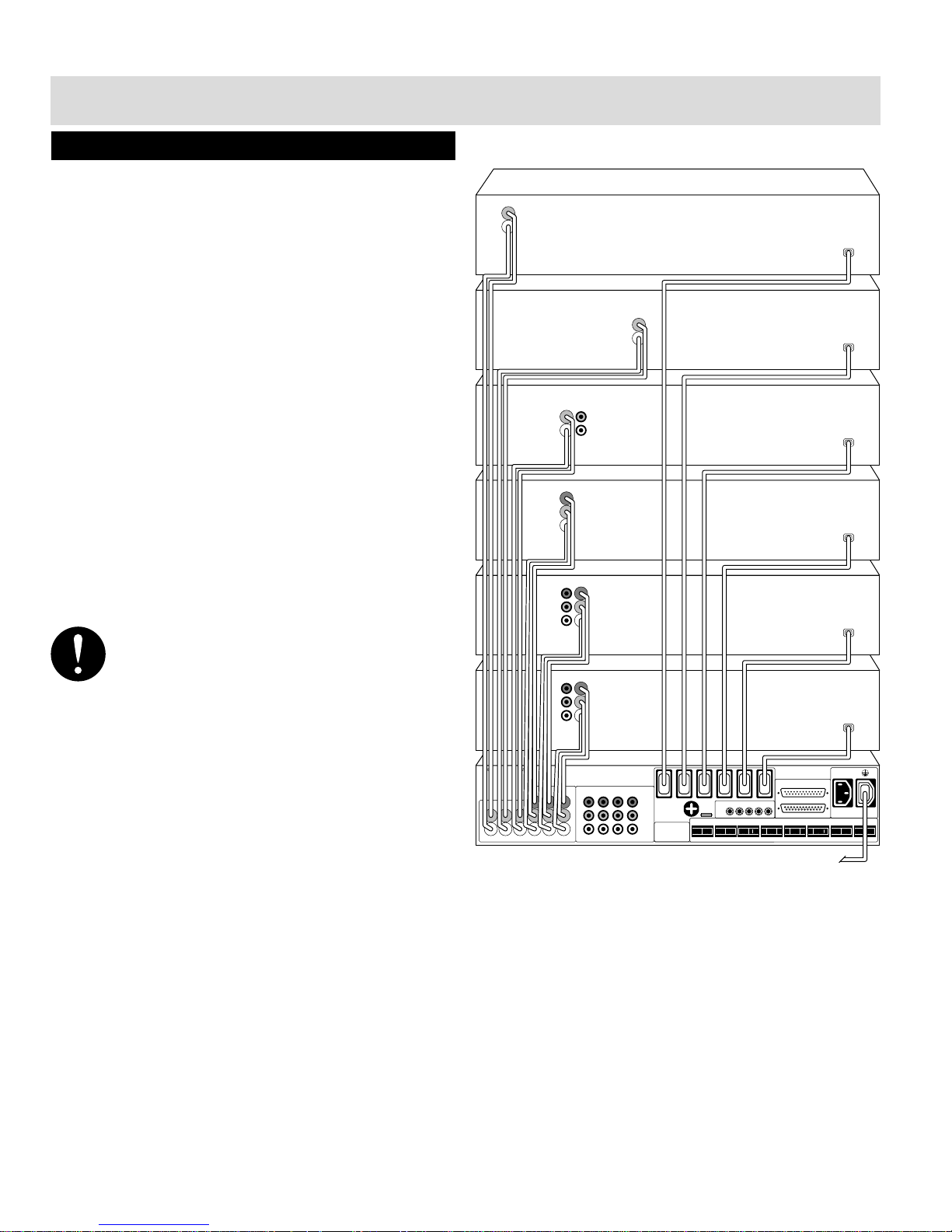
Make line level and composite video connections from
source equipment to PR-4Z as shown in Figure 3. Use high
quality audio and audio/video cables and make cable length
as short as possible to keep signal integrity intact. The PR-4Z
provides switched two-pole 115 VAC outlets designed to
supply power to low current devices such as CD players, tape
decks and/or VCRs etc.. All switched AC outlets are active
when any zone within a PR-4Z system is “ON”. When all
zones are turned off, the PR-4Z will wait five minutes and
then turn off the AC outlets. All six of the two pole AC outlets can supply a combined current output of 1 Amp max.
If using a Four Zone Audio Amplifier, make audio connections from the PR-4Z to the amplifier as shown in Figure 5.
Use good quality audio cables and keep cable length as short
as possible to keep signal integrity intact. A single high current 115 VAC, three prong switched outlet is provided to
allow power connection to the amplifier. The high current
AC outlet can supply a maximum current output of 8 Amps.
If using multiple stereo amplifiers, make audio connections
as shown in Figure 6.
WARNING : DO NOT MAKE A CONNECTION TO THE
HIGH CURRENT SWITCHED AC OUTLET THAT
REQUIRES MORE THAN 8 AMPS MAX.
Figure 3 – Source Component Connections
AC 115V~
60HZ XA
L
R
LEFT
VIDEO
RIGHT
INPUTS
CD 4321AUXVID2VID1TAPETUNER
INPUTS OUTPUT TO ZONES
WARNING: SHOCK HAZARD – DO NOT OPEN
AVIS: RISQUE DE CHOC ELECTRIQUE – NEZ PAS OUVRIR
SWITCHED
AC OUTLETS
115V~ 60HZ
1A MAX TOTAL
FUSE
10 AMP
IR
OUT
CMN1234
KEYPAD 1 KEYPAD 2 KEYPAD 3 KEYPAD 4 PAGE 1 PAGE 2 PAGE 3 PAGE 4
D2D1GV+D2D1GV+D2D1GV+D2D1G
V+
V G S T V G S T V G S T V G S T
SWITCHED
OUTLET
UNIT INTERFACE
8A MAX
RUSSOUND
NEWMARKET, NH
MADE IN USA
AA
BB
VCR 2
VCR 1
LASER DISC PLAYER
TAPE DECK
CD PLAYER
TUNER
115 VAC~
115 VAC~
115 VAC~
115 VAC~
115 VAC~
115 VAC~
TO UN-SWITCHED
115 VAC
WALL OUTLET

6
WIRING INSTRUCTIONS
L
R
MAIN
INPUT
MAIN
OUTPUT
TO 115 VAC
WALL OUTLET
+
-
OUTPUT
150 W/CH RMS
4-8 OHMS
RIGHT LEFT
L
R
MAIN
INPUT
MAIN
OUTPUT
TO 115 VAC
WALL OUTLET
+
-
OUTPUT
150 W/CH RMS
4-8 OHMS
RIGHT LEFT
L
R
MAIN
INPUT
MAIN
OUTPUT
TO 115 VAC
WALL OUTLET
+
-
OUTPUT
150 W/CH RMS
4-8 OHMS
RIGHT LEFT
AC 115V~
60HZ XA
LEFT
VIDEO
RIGHT
CD 4321AUXVID2VID1TAPETUNER
INPUTS OUTPUT TO ZONES
WARNING: SHOCK HAZARD – DO NOT OPEN
AVIS: RISQUE DE CHOC ELECTRIQUE – NEZ PAS OUVRIR
SWITCHED
AC OUTLETS
115V~ 60HZ
1A MAX TOTAL
FUSE
10 AMP
IR
OUT
CMN1234
KEYPAD 1 KEYPAD 2 KEYPAD 3 KEYPAD 4 PAGE 1 PAGE 2 PAGE 3 PAGE 4
D2D1GV+D2D1GV+D2D1GV+D2D1G
V+
V G S T V G S T V G S T V G S T
SWITCHED
OUTLET
UNIT INTERFACE
8A MAX
RUSSOUND
NEWMARKET, NH
MADE IN USA
AA
BB
L
R
MAIN
INPUT
MAIN
OUTPUT
TO UN-SWITCHED
115 VAC
WALL OUTLET
TO 115 VAC
WALL OUTLET
+
-
OUTPUT
150 W/CH RMS
4-8 OHMS
RIGHT LEFT
POWER
AP-48
POWER
TUNER
12
34
ZONE SELECT
ON / OFF
CD TAPE VIDEO 1 VIDEO 2 AUX
PR-4Z
ALL
ON
ALL
OFF
4321
BASS
TREBLE
LOUDNESS PART Y MEM PRESET
SOURCE LOCK
SOURCE LINK
VOLUME
AC 115V~
60HZ XA
LEFT
VIDEO
RIGHT
L
R
MAIN
BUS
INPUT
MAIN
BUS
OUTPUT
CD 4321AUXVID2VID1TAPETUNER
INPUTS OUTPUT TO ZONES
WARNING: SHOCK HAZARD – DO NOT OPEN
AVIS: RISQUE DE CHOC ELECTRIQUE – NEZ PAS OUVRIR
SWITCHED
AC OUTLETS
115V~ 60HZ
1A MAX TOTAL
FUSE
10 AMP
IR
OUT
CMN1234
FUSE
10 AMP
FUSE
10 AMP
KEYPAD 1 KEYPAD 2 KEYPAD 3 KEYPAD 4 PAGE 1 PAGE 2 PAGE 3 PAGE 4
D2D1GV+D2D1GV+D2D1GV+D2D1G
V+
V G S T V G S T V G S T V G S T
SWITCHED
OUTLET
UNIT INTERFACE
8A MAX
RUSSOUND
NEWMARKET, NH
MADE IN USA
AA
BB
L
R
LINE INPUT
SPEAKERS
4 OHM MIN
AMP OUT
L+ L- R- R+
BUS
LINE
MONO
STEREO
L
R
LINE INPUT
SPEAKERS
4 OHM MIN
AMP OUT
L+ L- R- R+
BUS
LINE
MONO
STEREO
L
R
LINE INPUT
SPEAKERS
4 OHM MIN
AMP OUT
L+ L- R- R+
BUS
LINE
MONO
STEREO
L
R
LINE INPUT
SPEAKERS
4 OHM MIN
AMP OUT
L+ L- R- R+
BUS
LINE
MONO
STEREO
TO UN-SWITCHED
115 VAC
WALL OUTLET
PART # 09-0505
115 VAC
JUMPER / POWER
CORD
Figure 4 – PR-4Z shown with z4-Zone Amplifier
Figure 5 – PR-4Z to 4-Zone Amplifier Wiring Configuration
Figure 6 – Multiple Stereo Amp Configuration
7
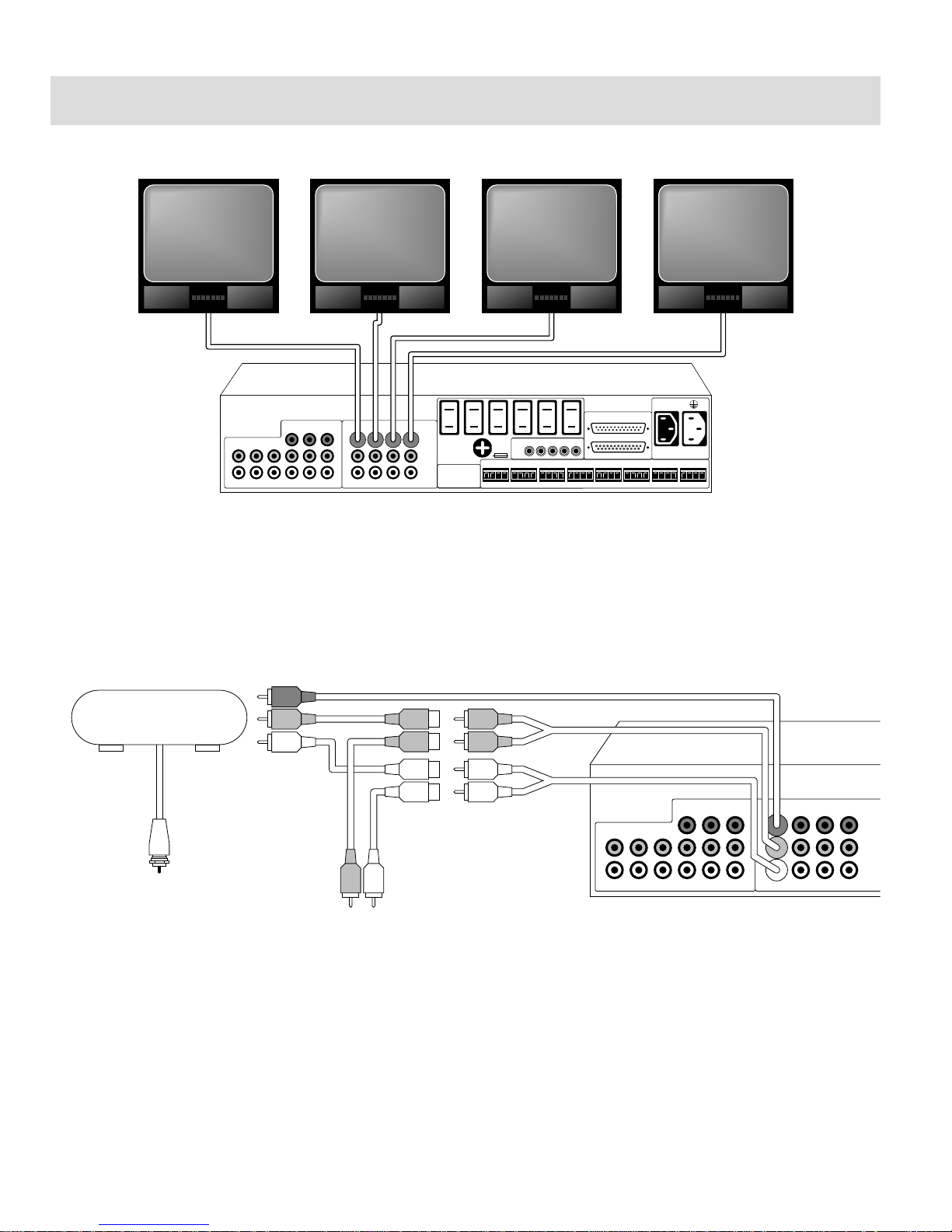
Figure 7 – Video Output Connections
Each zone has a video output to allow viewing of any of the three audio/video sources. Monitors can be
connected to each of the 4 zone outputs as shown in Figure 7 using RG6U cable with RCA type connectors. If more than
two monitors are being used in a given installation on any given zone, it is recommended that composite line amplifiers be
used. The PR-4Z video outputs are buffered and are good for up to 100’ of RG6U to one monitor/zone.
Figure 8 – Video Output Connections With RF Modulators
Video may also be distributed utilizing RF modulators, such as the Channel Plus model# 5415 modulator shown in Figure 8.
Use “Y” cables to distribute audio to both the dedicated amplifier and modulator.
WIRING INSTRUCTIONS
AC 115V~
60HZ XA
L
R
LEFT
VIDEO
RIGHT
INPUTS
CD 4321AUXVID2VID1TAPETUNER
INPUTS OUTPUT TO ZONES
WARNING: SHOCK HAZARD – DO NOT OPEN
AVIS: RISQUE DE CHOC ELECTRIQUE – NEZ PAS OUVRIR
SWITCHED
AC OUTLETS
115V~ 60HZ
1A MAX TOTAL
FUSE
10 AMP
IR
OUT
CMN1234
KEYPAD 1 KEYPAD 2 KEYPAD 3 KEYPAD 4 PAGE 1 PAGE 2 PAGE 3 PAGE 4
D2D1G
V+
D2D1G
V+
D2D1G
V+
D2D1G
V+
V G S T V G S T V G S T V G S T
SWITCHED
OUTLET
UNIT INTERFACE
8A MAX
RUSSOUND
NEWMARKET, NH
MADE IN USA
AA
BB
L
R
LEFT
VIDEO
RIGHT
INPUTS
CD 4321AUXVID2VID1TAPETUNER
INPUTS OUTPUT TO ZONES
WARNING: SHOCK HAZARD – DO NOT OPEN
AVIS: RISQUE DE CHOC ELECTRIQUE – NEZ PAS OUVRIR
CHANNEL PLUS
PART # 5415 OR 5400 SERIES
MODULATOR
TO TELEVISION CABLE INPUT
TO AMPLIFIER
"Y" CABLE
"Y" CABLE
8
PR-4Z CONTROL FEATURES
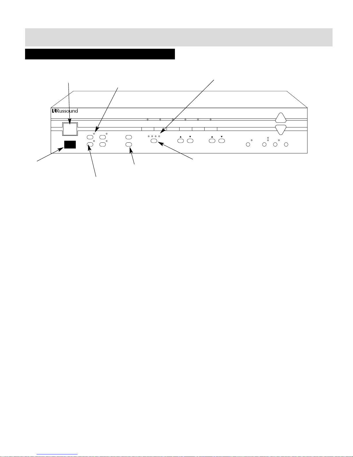
Figure 9 – Zone Control Functions
1) Master Power Switch – Controls power to entire PR-4Z system (including switched outlets). The “0” indicator signifies
power off, the symbol “I” signifies power on.
2) Infra-Red Receiver – Provides IR control for zone #1. The IR receiver located on the front of the PR-4Z will provide control for the #1 zone of the PR-4Z and will not pass common IR codes.
3) Zone Select Buttons – Selects zone (1-4) to be displayed and/or accessed on PR-4Z front panel.
4) Zone Select Indicators – Indicates which zone (1-4) is currently displayed on the PR-4Z front panel (“current zone”).
5) All On / All Off – Turns all zones on and off respectively. The All On command may be “preset” such that a zone/zones
may be selectively omitted from the All On function (see memory procedure). The All Off function, in addition to turning
off all zones, can be used to control the power to additional equipment, such as a 4-Zone Amplifier, CD player, etc.
through the use of the seven switched AC outlets located on the rear of the PR-4Z. When all zones in a PR-4Z system are
turned off through use of the All Off feature or independently, the PR-4Z will turn off the switched AC outlets after waiting five minutes. If it is desired that the AC switched outlets be turned off immediately, press the All Off button twice.
6) Current Zone On / Off – On / Off control for zone currently displayed.
7) Zone On / Off Indicators – Shows On / Off status of zone currently displayed.
CONTROL FEATURES
TUNER
12
ON/OFF
ZONE SELECT
POWER
ALL
ON
ALL
OFF
BASS TREBLE
LOUDNESS PARTY
SOURCE LINK
SOURCE LOCK
MEMORY
VOLUME
PRESET
34
CD TAPE VIDEO 1VIDEO 2DVD
4 Z
ONE
— 6 S
OURCE AUDIO/VIDEO PREAMPLIFIER
PR-4Z
12
34
1 - Master Power Switch
2 - Infra-Red Receiver
3 - Zone Select Buttons
4 - Zone Select Indicators
5 - All On / All Off
6 - Current Zone On / Off
7 - Zone On / Off Indicators
9
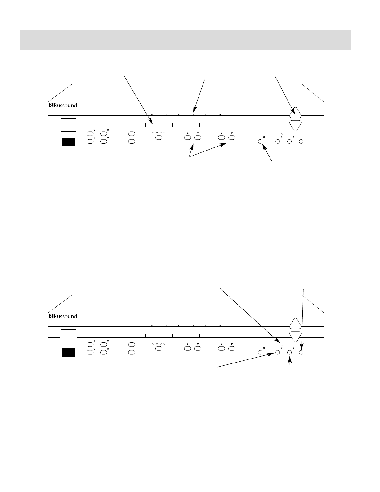
Figure 10 – Audio Control Functions
1) Source Select Buttons – Changes source input for current zone.
2 Source Indicators – Displays which source input is selected for current zone.
3) Volume Control – Controls volume (up/down) for current zone. Volume control: 40 step, 2db each step
(-80dB to 0 dB).
4) Bass & Treble Controls – Control bass and treble (up/down) respectively for current zone. Bass and treble controls: 12 step
each, 2dB each step (-12dB to +12dB).
5) Loudness Control – Selects loudness on / off for current zone. Loudness allows greater bass and treble response at lower
volume levels.
Figure 11 – Advanced Control Functions
1) Memory Button – Begins preset storage routine to customize the current zone (see memory procedure).
2) Preset Button – Accesses stored preset information (see memory / preset procedure).
3) Party Mode Button – Selects 1 of 3 operating modes (normal, Source Lock, Source Link) (see party modes procedure).
4) Party Mode Indicators – Indicates which operating mode is being used (see party modes procedure).
CONTROL FEATURES
TUNER
12
ON/OFF
ZONE SELECT
POWER
ALL
ON
ALL
OFF
BASS TREBLE
LOUDNESS PARTY
SOURCE LINK
SOURCE LOCK
MEMORY
VOLUME
PRESET
34
CD TAPE VIDEO 1VIDEO 2DVD
4 Z
ONE
— 6 S
OURCE AUDIO/VIDEO PREAMPLIFIER
PR-4Z
12
34
1 - Source Select Buttons
2 - Source Indicators
3 - Volume Control
4 - Bass & Treble Controls
5 - Loudness Control
TUNER
12
ON/OFF
ZONE SELECT
POWER
ALL
ON
ALL
OFF
BASS TREBLE
LOUDNESS PARTY
SOURCE LINK
SOURCE LOCK
MEMORY
VOLUME
PRESET
34
CD TAPE VIDEO 1VIDEO 2DVD
4 Z
ONE
— 6 S
OURCE AUDIO/VIDEO PREAMPLIFIER
PR-4Z
12
34
1 - Memory Button
2 - Preset Button
4 - Party Mode Indicators
3 - Party Mode Button

10
ADVANCED CONTROL FUNCTION PROCEDURES
MEMORY PROCEDURE
The Memory function allows information for each zone to
be individually stored, then later accessed by using the preset function. Source, volume level, treble level, bass level,
loudness, and “All On disable” can be stored individually for
each zone.
1) Select the zone you wish to establish presets for, using
the Zone Select
2) Setup all or some of the zone characteristics including
source, volume, bass, treble and loudness to what is
desired.
3) Press the Memory button (Figure 11); the Memory
Indicator will light.
4) To store volume, bass and/or treble levels, press either the
up or down button that corresponds to the characteristic
to be stored.
5) To store current source input selection, press any source
button.
6) To store loudness (on or off) press the Loudness button
(Figure 10).
7) To prevent the zone from turning on when the All On
function is activated, press the All On button.
8) To exit memory mode, press the Memory button until the
Memory Indicator is no longer illuminated.
NOTE: To clear memory, select zone, press Memory
button until Memory Indicator is illuminated, press
Preset button (Figure 11), press Memory button
until Memory Indicator is no longer illuminated.
NOTE: If the main power switch of the PR-4Z is
turned off, all information stored in memory will be
lost!! Use of a UPS power backup device will elimi-
nate this problem as well as offering surge protection.
PRESET PROCEDURE
The Preset function will access information previously stored
in memory and automatically set zone characteristics (volume level etc.) to those stored in memory. The Preset function may be accessed at the PR-4Z front panel, PCK-IR keypad or through an IR receiver.
1) Select zone using the Zone Select buttons (Figure 11).
2) Make certain that the zone has settings stored in memory. If there are no settings stored follow the memory procedure to establish presets.
3) Press the Preset button.
4) Zone characteristics should now reflect what was previously stored in memory.
PARTY MODE PROCEDURE
Party Mode allows synchronous operation of all zones which
are listening to a single source (CD player etc..). Two modes
are provided to accommodate different control criteria.
1) Set zone 1 volume and source to the desired setting for
the entire system. Turn on those zones you wish to have
“participate” in party mode operation.
2) Press the Party Mode button. The Source Lock indicator
will light and the source and volume level which was initially set in step 1 will be reflected in all other zones (2-4)
which were turned on when the Party Mode button was
initially pressed.
3) The system is now in Source Lock Mode. In this mode,
once the initial setup (step 2) of volume level and source
was uploaded to zones 2, 3 and 4 is complete, you can
now adjust volume independently in all zones from either
keypad, IR receiver or front panel. In Source Lock Mode,
source changes can only be made from the front panel;
keypads and IR receivers are unable to make source
changes.
4) If the Party Mode button is pressed a second time, the
Source Link indicator will light. Source selection for all
zones at this point is linked, so that if any zone changes a
source, all other zones will follow. Source link will operate
similarly to Source Lock except that whole-house source
changes can be made from any keypad, IR receiver or
front panel.
5) To exit Party Mode operation, press the Party Mode button until both the Source Lock and Source Link indicators
are no longer illuminated.
6) To use the Party Modes with multiple PR-4Zs which are
using the interface cable connection, setup each of the
PR-4Zs’ zone 1 to the desired volume and source setting.
Press the Party Mode button until the desired mode is
selected. Source changes will now be linked between all
zones.

11
PERIPHERAL DEVICES
PCK KEYPAD WIRING INSTRUCTIONS
Figure 12 – PCK-IR (Front View)
Figure 13 – PCK-IR (Rear View)
Each of the PR-4Z’s zones can be remotely operated by use
of the keypad (1-4) ports located on the rear of the PR-4Z.
Each of the keypad ports allow connection of up to 4
Russound model PCK-IR keypads (4 per zone). The PR-4Z’s
keypad ports are also compatible with Infra-Red devices such
as Russound infrared receivers (Model #’s 848, 1257, 1258
and 844). It is also possible to control the PR-4Z with learning devices that transmit IR codes in this manner.
Figure 14 – PCK-IR Wiring Configuration
Wire the PCK-IR keypads to
the PR-4Z keypad input as
shown in Figure 14 using 22-
24 AWG shielded two twisted
pair wire.
NOTE: Though we don’t recommend CAT5 be used
on such products and encourage the use of 22AWG
twisted shielded pair, we recognize many companies
use and prefer CAT5. If using CAT5 it is important to
use the following connections.
PR-4Z WITH CAT5
Due to the characteristics of CAT5 it is recommended that
the following color code be utilized for proper performance
when used with the PR-4Z. Both Orange and Green CAT5
paris have a higher twist ratio than the Blue and Brown
pairs. This makes them the best pairs for D1 and D2 signal
lines. By doubling up on both the Voltage and Ground,
power supplied to the keypad will have less resistance. By
grounding the Green/White and Orange/White lines at the
PR-4Z, RF noise has less of a chance of being induced into
the control lines of D1 and D2.
CAT5 PR-4Z KEYPAD
Blue V 12V+ V 12V+
Blue/White Ground Ground
Brown V 12V+ V 12V+
Brown/White Ground Ground
Green D1 D1
Green/White Ground NONE
Orange D2 D2
Orange/White Ground NONE
TREBLE VOLUMEBASS
PR-4Z SYSTEM CONTROLLER
SELECT
CD TAPETUNER
VID2 DVDVID1
ZONE
ON/OFF
PRESETLOUD
SYSTEM
OFF
SYSTEM
ON
D2
D1
GND
V+
D2
D1
GND
V+
KEYPAD 1 KEYPAD 2 KEYPAD 3 KEYPAD 4
D2
D1
G
V+
D2
D1
G
V+
D2
D1
G
V+
D2
D1
G
V+
4 CONDUCTOR
2 TWISTED PAIR WIRE
WITH SHEILD

12
PERIPHERAL DEVICES
INFRARED DEVICE WIRING INSTRUCTIONS
Figure 15 – Infra-Red Receiver Wiring Configuration
Wire Infra-Red receivers as shown in Figure 15 using 22-24
AWG 1 pair twisted wire with shield. Wiring configuration
also applies to other manufacturers’ programmable keypads.
PCK-IR CONTROL FEATURES
Figure 16 – PCK-IR Zone Control Functions
1) On / Off Button – Turns zone on / off.
2) Preset Button – Accesses stored preset information (see
memory / preset procedure).
3) Infrared Receiver – Provides IR control of zone and
source equipment through the keypad.
4) System Off Button – Turns all zones off.
5) System On Button – Turns all zones on.
Figure 17 – PCK-IR Audio Control Functions
1) Bass / Volume / Treble Select Indicators – Indicates
which function is selected to be adjusted.
2) Select Button – Selects which function (volume, bass,
treble) is to be adjusted by the up / down control buttons.
3) Up / Down Control Buttons – Provides up / down control
for volume, bass, and treble.
4) Source Select Buttons – Selects and indicates source
input.
5) Loudness Button – Selects and indicates loudness on /
off for zone.
TREBLE VOLUMEBASS
PR-4Z SYSTEM CONTROLLER
SELECT
CD TAPETUNER
VID2 DVDVID1
ZONE
ON/OFF
PRESETLOUD
SYSTEM
OFF
SYSTEM
ON
1 - On / Off Button
2 - Preset Button
3 - Infrared Receiver
4 - System Off Button
5 - System On Button
TREBLE VOLUMEBASS
PR-4Z SYSTEM CONTROLLER
SELECT
CD TAPETUNER
VID2 DVDVID1
ZONE
ON/OFF
PRESETLOUD
SYSTEM
OFF
SYSTEM
ON
1 - Bass / Treble / Volume
Select Indicators
3 - Up / Down Control
Buttons
2 - Select Button
4 - Source Select Buttons
5 - Loudness Button
KEYPAD 1 KEYPAD 2 KEYPAD 3 KEYPAD 4
D2D1G
V+
D2
D1GV+
D2
D1
G
V+
D2
D1GV+
1 PAIR TWISTED WIRE
WITH SHEILD
GND
OUT
N / C
+12V
MODEL #848
J-BOX RECIEVER

13
PERIPHERAL DEVICES
SPG & PTM-1 PAGING MODULES
Figure 18 – SPG (Front View)
The PR-4Z is equipped with 4 paging Inputs. The PR-4Z is configured
to page to all zones (except the
zone where the page originates) at
the preset volume level (if set) or
half volume (if no volume level is
stored into memory). The PR-4Z
paging feature is also configured to
automatically turn on zones which
may be turned off as well as any
equipment attached to the AC
switched outlets when a page is active. Multiple paging
accessories are available to meet the needs of most any
application. Call Russound for information on which paging
accessories would best fit your application.
Figure 19 – SPG Wiring Configuration
The SPG Paging Module provides “Push-to-Talk” paging
operation. Use 22-24 AWG twisted pair shielded wire to connect the SPG to the PR-4Z page input as shown in Figure 19
Figure 20 – PTM-1 Wiring Configuration
The PTM-1 Paging Module is a signal sensing paging
adapter for the PR-4Z which will accept the page
output or other line-level audio output from telephone
paging systems, paging preamplifiers, switch triggered
voice/sound recording devices etc. Use 22-24 AWG
twisted pair shielded wire to connect the PTM-1 to the
PR-4Z page input as shown in Figure 20.
Figure 21 – PTM-1 Used With Visonic Ltd. Model# SP-2S
Switch Triggered Voice / Sound Recorder
By using Voice / Sound Recording devices such as the Visonic
Ltd. Model SP-2S, systems may be configured to playback
recorded sound (i.e. doorbell chime, or voice indicators such
as “Front Door” etc.). Call Russound for availability.
Figure 22 – PTM-1 Settings
Adjust PTM-1 trigger, delay and
audio adjustments shown in
Figure 22 as described in the
PTM-1 instruction manual.
VGS T
PAGE INPUT
4 CONDUCTOR TWISTED
PAIR SHEILD
TGR
GND
SIG
12+
PAGING MODULE
PUSH TO TALK
MICROPHONE
VGS T
PR-4Z PAGE INPUT
TSGV
PTM-1 PAGE TRIGGER MODULE
ON TGR
IN
OUT
OUT
PAGE
VGS T
PR-4Z PAGE INPUT
TSGV
PTM-1 PAGE TRIGGER MODULE
ON TGR
IN
OUT
+12V
GND
ST+
ST-
SP+
SP-
VISONIC LTD.
MODEL #SP-2S or SP-5
SWITCH TRIGGERED
VOICE / SOUND RECORDER
Visonics Tel# 800-223-0020
SWITCH
OR RELAY
SP+ CONNECTED TO
CENTER CONDUCTOR ,
SP- TO CONNECTOR
SHROUD
TGR to T
GND to G
SIG to S
12+ to V
TRIGGER DELAY AUDIO

14
PERIPHERAL DEVICES
PR-4Z IR EMITTER OUTPUTS
The PR-4Z has 5 IR emitter outputs located on the rear
panel: Zone 1, Zone 2, Zone 3, Zone 4 and Common. The
Zone 1-4 outputs provide IR signal out from their respective
zones, while the Common output provides IR signal output
for all zones. The Common output would most likely be used
most often to control source equipment, such as CD players
etc.. The Zone 1-4 outputs can be used to control IR controllable equipment which is proprietary to a particular zone ie.
IR controlled drapes, zone specific sources, etc.
Figure 23 – Zone Specific Infra-Red Outputs Using Single
Emitters
Figure 24 – Common Infra-Red Output Connections Using
#847 Connecting Block as an Emitter Expander
To connect multiple emitters to a single IR output, use
Russound Model# 847 connecting block and an 1/8” 2 conductor (mono) phone plug as shown in Figure 24. Wire the
“tip” of the phone plug to the signal terminal of the #847
and the “ sleeve” to the ground terminal.
IR
OUT
CMN1234
#845 MICRO EMITTER TO
IR RECEIVER WINDOW
OF ZONE 1 EQUIPMENT
IR
OUT
CMN1234
#845 MICRO EMITTERS
TO IR CONTROLLED
EQUIPMENT
#847 CONNECTING BLOCK
TIP
SLEEVE
1/8" (MONO)
PHONO PLUG
WIRE WITH
STRIPE IS SIG

15
PERIPHERAL DEVICES
PRC-1 REMOTE CONTROL
The Russound PRC-1 remote control is preprogrammed to
operate over 1000 Audio and Video components, including
the PR-4Z. Set it up by simply punching in a three digit code
number that matches your equipment. The PRC-1 also has
the ability to learn new functions from your original remote
controls, allowing you to customize the remote to your own
needs and update it as you add new equipment. The PRC-1
operates up to eight different audio and video devices in
your home entertainment system and has the 5 available
macros.
Figure 25 – PRC-1 Preprogrammed & Learning Remote
Control
PROGRAMMING FOR PR-4Z FUNCTIONS
Program the remote by first turning on the PR-4Z manually.
Press the PR-4Z (AUX) and MUTE buttons simultaneously to
get the SET prompt. Point the remote toward the PR-4Z and
press the three digit code 081. Press the PR-4Z (AUX) button
again to store the code.
If there is difficulty programming the PRC-1 Remote Control
with the standard 081 Russound IR Code in the PR-4Z (AUX)
position, the code may be found in another location. Code
267 in the AUD position will also control Russound products.
This code can be moved to the PR-4Z (AUX) location. The
following describes how to do this.
The 267 code is programmed into the AUD position by pressing AUD and MUTE simultaneously to get the SET prompt.
Then enter 267, press AUD and the remote will show STORE.
To move the code to the PR-4Z (AUX) position, press PR-4Z
(AUX) and MUTE simultaneously to get the SET prompt.
Press AUD, enter 267 then press PR-4Z (AUX). The remote
will give the STORE indication on the display showing that
the 267 code in the AUD bank has been stored into the AUX
position.
OPERATING THE PR-4Z WITH THE REMOTE
Pressing the PR-4Z button in the upper right corner of the
remote accesses all the preprogrammed codes for the PR-4Z.
All the functions available on the PR-4Z Keypad are available
on the remote. Note: The remote will only control the zone
you are in.
The remote is capable of controlling source selections on the
PR-4Z by pressing one of six source buttons. Pressing these
buttons will change the input on the PR-4Z. The remote can
also control bass, treble, volume and "loudness" for the zone
you are in. The loudness button provides more bass and treble at lower volume levels for a fuller, richer sound. The
remote can turn on the zone you are in by pressing the
POWER button, and turn off that zone by pressing the
MUTE button. The remote also has buttons to turn on and
off all zones.
TU
N
ER
CD TAPE
VID
1
VID
2
D
VD
ALL O
N
SYSTEM
O
N
SYSTEM
O
FF
ALL O
FF
PRESET
SH
IFT
SLEEP
PRO
.L
3.CH
TEST
BASS TREBLE
TUNER
TAPE CEN
TER
REAR CEN
TER
D
ELAY
SU
RR
L
d
PR-4Z
PIP
PRC-1
PRO
G
RAM
M
ABLE REM
O
TE CO
N
TRO
L

16
The Unit interface connections on the rear of the PR-4Z provide connections required for multiple unit interaction (4 PR-4Zs
max.). The interface connections will link any multi-zone function such as ALL ON, ALL OFF, PAGING, and PARTY MODES so
that these functions can be used system-wide with multiple PR-4Zs. Your PR-4Z comes equipped with 2 female DB-25 connectors. Use male-to-male straight pass-through DB-25 cables only to make all connections, as shown in Figure 26.
MULTIPLE CONTROLLERS
AC 115V~
60HZ XA
L
R
LEFT
VIDEO
RIGHT
INPUTS
CD 4321AUXVID2VID1TAPETUNER
INPUTS OUTPUT TO ZONES
WARNING: SHOCK HAZARD – DO NOT OPEN
AVIS: RISQUE DE CHOC ELECTRIQUE – NEZ PAS OUVRIR
SWITCHED
AC OUTLETS
115V~ 60HZ
1A MAX TOTAL
FUSE
10 AMP
IR
OUT
CMN1234
KEYPAD 1 KEYPAD 2 KEYPAD 3 KEYPAD 4 PAGE 1 PAGE 2 PAGE 3 PAGE 4
D2D1G
V+
D2D1G
V+
D2D1G
V+
D2D1G
V+
V G S T V G S T V G S T V G S T
SWITCHED
OUTLET
UNIT INTERFACE
8A MAX
RUSSOUND
NEWMARKET, NH
MADE IN USA
AA
BB
DB-25
MALE / MALE
CONNECTOR
Figure 26 – Interface Cable Connections

17
Frequency Response: 20 - 20kHz + 0.1 dB max.
Total Harmonic Distortion: 0.06% max.
Signal-to-Noise Ratio: 95 dB min, “A” weighted
Maximum input voltage: 4.6 VRMS, 6 Volts peak
Maximum output voltage: 8.5 VRMS, 12 Volts peak
Volume Control: 0 dB to -80 dB (40 step)
Bass and Treble Controls: +/- 12 dB (12 step)
Standard Features: 6 source inputs (3 audio, 3 audio/video)
Expansion ports allow cascading of up to four Pr-4Zs (16 zones)
4 stereo audio/video outputs
4 keypad / Infrared ports
4 Paging unit ports
7 Switched AC outlets
5 Infrared transport outputs (4 zoned, 1 Common)
Built-in IR receiver for zone #1 PR-4Z functions only
Optional Features: Full function PCK-IR keypad w/ built-in IR receiver
Full function PCK keypad with no IR receiver
DCS & DAN Programmable source control learning keypads
SPG In-wall paging module
PTM-1 telephone paging interface module
PRC-1 Remote Control
DTI-1 Doorbell Telephone interface with optional TPM-1 paging interface.
Power requirements (USA & Canada only): AC 120 Volts 60Hz 10 AMPS.
Dimensions: 17” W x 12” D x 3.6” H.
Weight: 12 lbs.
The PR-4Z complies with the requirements of the standards for Audio Video Products and Accessories (UL 1492, 1st Edition)
and Radio, Television, and Electronic Apparatus (CSA C22.2 No. 1-M94).
TECHNICAL SPECIFICATIONS

18
WARRANTY
The Russound PR-4Z is fully guaranteed for two (2) years from the date of purchase against all defects in materials and workmanship. During this period, Russound will replace any defective parts and correct any defect in workmanship without charge
for either parts or labor. For this warranty to apply, the unit must be installed and used according to its written instructions.
If service is necessary, it must be performed by Russound. The unit must be returned to Russound at the owner’s expense and
with prior written permission. Accidental damage and shipping damage are not considered defects under the terms of the
warranty. Russound assumes no responsibility for defects resulting from abuse or servicing performed by an agency or person
not specifically authorized in writing by Russound. Damage to or destruction of components due to improper use voids the
warranty. In these cases, the repair will be made at the owner’s expense. To return for repairs, the unit must be shipped to
Russound at the owner’s expense, along with a note explaining the nature of the service required. Be sure to pack in a corrugated container with at least 3 inches of resilient material to protect the unit from damage in transit.

19
NOTES

A/V DISTRIBUTION & CONTROL SYSTEMS
5 Forbes Rd. Newmarket, NH 03857
☎ 603.659.5170 • Fax 603.659.5388
e-mail: tech@russound.com
Fax-On-Demand: 603.659.5590
Come visit us at:
28-0071 R5

PR-4Z TESTING PROCEDURE
The purpose of this Test Procedure is to instruct both the Russound Test
Department and any outside Service Technician.

01/21/99
NOTE: Before testing the PR-4Z Multi-Channel Preamp, it is required that
the tester has a full working knowledge of the PR-4Z and its operation.
The PR-4Z instruction manual is required reading material before testing.
From the PR-4Z front panel, perform the following tests.
1) Start up
Connect a PR-4ZKP Keypad to the zone 1 keypad input. Turn on the unit. You should
hear the power relays click on. Only the Zone 1 light should be on and no other lights should be
lit. Press All On to turn on all four zones.
2) Zone 1 reset
Change the front to a zone other than zone 1. After 30 seconds the front should reset
to Zone 1.
3) ON/OFF
Turn off zone by pressing the appropriate On/Off button on the front panel then turn it
back on. The ON/OFF light for that zone should turn off and back on.
4) Source Lights
Press each of the six source buttons. Each source light should light as soon as the
button is pressed and the previous light should go off.
5) Loudness
Turn on and off loudness. The loudness light should turn on and off on the front panel.
6) Memory/Preset light
Press MEM, Memory light (green) should light.
Press MEM. Memory light should go off.
7) Party Mode Lights
Press PARTY, Red Source Lock light should light
Press PARTY, Green Source Link light on, Red Source Lock light off
Press PARTY, Both party lights off
8) ALL OFF
With all zones on press ALL OFF
First press all zones turn off
Second press AC relay switches off (clicks)

9) Sources
a.) Connect a CD player to the Source 1 input, an amplifier to the Zone 1 output and
speakers to the amplifier output.
b.) Put Zone 1 on to Source 1 (Tuner). The CD should be playing through the speakers.
Listen to the left and right source inputs independently, then together.
c.) Repeat steps 9a and 9b for all the source inputs.
10) ON/OFF
Play the CD player through the zone at a comfortable level. Turn off zone by pressing the
zone On/Off button on the front panel then turn it back on. The volume should be
completely muted while the zone is tuned off.
11) VOLUME UP/DOWN
Press Volume up, Volume should go up.
Press Volume Down, Volume should go down.
12) BASS UP/DOWN
Press Bass Down, bass should decrease.
Press Bass Up, bass should increase.
13) BASS FLAT
Press bass up several (12) times until bass is at full.
Press BASS UP and BASS DOWN at the same time. The bass level should drop down
to flat.
14) TREBLE UP/DOWN
Press Treble Down, Treble should decrease.
Press Treble Up, Treble should increase.
15) TREBLE FLAT
Press Treble up several (12) times until Treble is at full.
Press TREBLE UP and TREBLE DOWN at the same time. The Treble level should
drop down to flat.
16) LOUDNESS
Press the Loudness button until the loudness indicator is lit. At a volume level lower
than half volume there should be an audible enhancement of both bass and treble
when the Loudness indicator is lit. This enhancement should decrease in intensity as
the volume level increases.
17) Memory / Preset
a.) Starting with zone 1, select source input as "CD", Volume at half, Bass- at full,
Treble- at full, Loudness on. (Make sure audio can be heard)
b.) Press the Memory button; the memory indicator will light.

c.) While the Memory indicator is lit, press the following buttons: Tuner, Volume UP,
Bass Up, Treble Up, Loudness.
d.) Press the Memory button until the Memory indicator is no longer lit.
e.) Select source input as "AUX", Volume all the way down, Bass- all the way down,
Treble- all the way down, Loudness off.
f.) Press the Preset button on the front panel. The zone should now reflect the
same settings as set up in step 17-a.
18) Party Mode
a.) Turn all zones on and connect a PR-4ZKP Keypad to the zone 1 keypad input
b.) Scroll through the sources on the keypad and front panel making sure they are
communicating correctly.
c.) Set zone 2,3 and 4 to source #6 (AUX), and volume all the way down.
d.) Set zone 1 to source #2 (CD), and volume at half.
e.) Press The Party button once; the Source Lock indicator will light.
f.) Zone 2,3 and 4 should now be set to source #2 (CD) and half volume.
g.) Source changes from any zone on the front panel of the PR-4Z should now
change source for all zones.
h.) The keypad connected to zone 1 should now be able to control the volume for
zone 1 only, and not be able to control source selection.
i.) Press the Party button; the Source Link indicator will light.
j.) Operation will be the same as when the system was in Source Lock mode except
the keypads should now be able to change the source for all zones from any
keypad input.
k.) Press the Party button; both of the Party LEDs will turn off and the PR-4Z should
return to normal operation.
19) Infra-Red Outputs
a.) Connect a PR-4ZKP to the zone 1 keypad input.

b.) Connect an 845 micro emitter to the zone 1 IR output on the rear of the PR-4Z,
and to the IR window of an IR controllable device such as the CD player used in
the above steps.
c.) Using a remote control which is programmed with the devices codes, aim the
remote at the keypad and control the device through the PR-4Z.
(Be sure that the device is not receiving the signal through its own IR receiver).
d.) IR signal should be present on the zone 1 and common output only. (All zones
output IR signal on the common and respective zone outputs only)
20) Repeat steps 9 through 19 for zones 2,3 and 4.
21) Infra-Red control
Change sources on zone 1 through the IR receiver on the front panel. Position the
keypad such that the IR is not going through it.
Cover the front panel IR receiver and change sources on zone 1 through the IR
receiver on the keypad.
22) Paging
a.) Connect a PR-4ZPG Paging Module to the zone 1 page input.
b.) Using the Memory / Preset procedure, preset volume for all zones to half
volume.
c.) Turn down volume all the way in all zones, and select source #5 (VIDEO2) in all
zones.
d.) Using the PR-4ZPG Paging Module, page.
e.) The page should be heard in all zones other than the zone where the page
originates, at the previously set volume (volume should be muted for in the zone
where the page originates).
f.) After the page is complete verify that each zone has returned to the settings in
step 24-c.
23) Repeat steps 24-a through 24-f for zones 2,3 and 4.
24) 115 VAC Switched Outlets
a.) Turn on the PR-4Z, and connect a CD Player's power cord to one of the 2 pole
AC outlets.
b.) Press the All-On button so that all zones are on.

c.) The CD player should work when connected to any of the 6 switched 2 pole
outlets.
d.) Leaving the CD player’s power connected, press the All-Off button, wait 2
seconds and press it again. There should be an audible "click" and the CD
player should turn off. The CD player should not work when connected to any of
the 6 2 pole AC outlets, and the device connected to the 3prong outlet should
turn off as well.
f.) Press the All-On button, the CD player should turn back on.
g.) Press the All-Off button once, the CD player should turn off in approximately 5
minutes.
25) Unit-to Unit Interaction
a.) Connect a second PR-4Z which will accept 3 Prong male AC input to the Female 3 prong
AC outlet on the PR-4Z with the 3 prong adapter cable.
b.) Press the ALL OFF button twice and the second PR-4Z should turn off. Connect each
PR-4Z into the power strip independently of each other.
c.) Connect the two preamps together with a DB-25 cable connected to each of the PR-4Z's
Unit Interface Connectors. Also connect a PR-4ZPG paging module to the zone 1 page
input on one of the PR-4Zs, and a CD player to one of the switched outlets on one of the
PR-4Zs.
d.) Turn on both PR-4Z's
e.) Press the All-On button on one of the PR-4Zs; all zones on both PR-4Zs should
turn on, and the CD player should be powered if connected to either PR-4Z's
switched outlets.
f.) Press the All-Off button twice on the other PR-4Z; all zones on both PR-4Zs
should turn off, and the CD should not work if connected to either PR-4Z's
switched outlets.
g.) Press All-On again such that all zones on both PR-4Zs are on.
h.) Press the Party mode button; both PR-4Zs should show the Source Lock LED
lit.
i.) Change sources from each of the PR-4Zs to ensure that source changes effect
all zones on both units.

j.) Press the Party mode button twice on one of the PR-4Zs; both PR-4Zs should
now return to normal operation.
k.) With the PR-4ZPG paging module connected to the zone 1 page input of one of
the PR-4Zs, initiate a page.
l.) The page should be heard in all zones on both PR-4Zs other than the zone
where the page originated.
m.) After the page is complete, all zones should return to their previous settings.
26) Video Test
a.) Press the ALL ON button; all four zones should light up.
b.) Set all four zones to Source 1.
d.) Connect a CD player to the Source 1 video input, an amplifier to the Zone 1 video output
and speakers to the amplifier output.
e.) Put Zone 1 on to Source 1. The CD should be playing through one speaker. Listen to the
left and right source inputs independently, then together.
f.) Repeat steps 9a and 9b for all the source inputs.
c.) Set the voltmeter to continuity (beep).
d.) Test for contact between zone 1 video and Aux video. Test for no contact between zone
1 video and other video inputs.
e.) Set zone 1 to source Video 2.
f.) Test for contact between zone 1 video and Video 2. Test for no contact between zone 1
video and other video inputs. Test for no contact between zones 2, 3 and 4 and Video 2.
g.) Set zone 1 to source Video 1.
h.) Test for contact between zone 1 video and Video 1. Test for no contact between zone 1
video and other video inputs. Test for no contact between zones 2, 3 and 4 and Video 1.
i.) Set zone 1 to source Aux.
j.) Repeat steps 26d through 26I for zones 2, 3 and 4.
27) Memory Zone Lock Out
a.) starting with zone 1, press the MEMORY button; the memory indicator will light.
b.) Press the ALL ON button; no lights should turn on.
c.) Press the MEMORY button.
d.) Press the ALL OFF button.
e.) Repeat steps 27a through 27d for zones 2, 3 and 4.
f.) Press the ALL ON button; no lights should turn on.
g.) Starting with zone 1, press the MEMORY button.
h.) Press the PRESET button.
i.) Press the MEMORY button.
j.) Repeat steps 27g through 27i for zones2, 3 and 4.
k.) Press the ALL ON button; all four zone indicator lights should turn on.

28) Ground Test
a.) Disconnect power, any accessories and/or additional PR-4Zs from the unit being
tested.
b.) With the cover removed, test continuity from the ground terminal of the power
input connector to the following points:
ground terminal of the 3 prong AC outlet
ground lug on the power supply
chassis main ground screw
chassis
power supply screw
ground plane on board
29) Hi-Pot Test
Perform Hi-Pot test @ 1200 V / 2 seconds.
30) Labels
Affix the Manufacturers date code, Serial #, Revision and ETL Labs stickers in their appropriate
positions.


PR-4Z Rear PCB.sch-1 - Wed Feb 07 15:44:38 2001

* Multi-Level Explosion By Parent Part Identifier *
Parent Part Identifier Range: PR-4Z - PR-4Z, Effective: 2/8/2001
LTOUMQCBTLLC
ECN #
SCR
Effectivity
Quantity
Part Identifier
Description
4 ZONE 6 SRCE A/V PREAMP
PR-4Z
SM PH PN 6 X 1/4 T-A BLK
07-0101
1
8.000000
6/9/1999
UEA 0N 0
CONN PLUG-IN 4 POLE BLACK
08-0106
1
8.000000
6/9/1999
UEA 0N 0
POWER CORD 16AWG/3COND
09-0504
1
1.000000
6/9/1999
UEA 0N 0
PWR CORD M/F 18AWG/3/BLK
09-0505
1
1.000000
6/9/1999
UEA 0N 0
LABEL DATE CODE STICKER
26-0505
1
1.000000
6/9/1999
UEA 0N 0
LABEL SERIAL NUMBER
26-0506
1
1.000000
6/9/1999
UEA 0N 0
ETL LABEL (VOL CONT)
26-0526
1
1.000000
6/9/1999
UEA 0N 0
CARTON PR-4Z
27-0024
1
1.000000
6/9/1999
UEA 0N 0
END PCS PR-4Z
27-1017
1
2.000000
6/9/1999
UEA 0N 0
BAG,PLASTIC 24" X 30"
27-1508
1
1.000000
6/21/1999
UEA 0N 0
BAG,PLASTIC 8" X 10"
27-1512
1
1.000000
1/8/2001
UEA 0N 0
MANUAL PR-4Z
28-0071
1
1.000000
6/9/1999
UEA 0N 0
COVER, PR-4Z
30-0643
1
1.000000
6/9/1999
UEA 0N 0
PR-4Z PREAMP ASSY
41-9505
1
1.000000
6/21/1999
UEA 0N 0
SW ARCOLECTRIC W/GLD SCRN
04-0212
.2
1.000000
12/28/1995
UEA 0N 0
SW BUTTON ARROW (BLACK)
05-0006C
.2
2.000000
12/28/1995
UEA 0N 0
SW BUTTON ROUND (BLACK)
05-0007C
.2
4.000000
12/28/1995
UEA 0N 0
SW BUTTON SOURCE (BLACK)
05-0008C
.2
6.000000
12/28/1995
UEA 0N 0
SW BUTTON OVAL (BLACK)
05-0009C
.2
11.000000
12/28/1995
UEA 0N 0
MS PH PN 6-32 X 3/4 BLK
07-0005
.2
1.000000
12/14/1999
UEA 0N 0
MS PH PN 6-32 X 1/4 W/LW
07-0021
.2
13.000000
8/26/1996
UEA 0N 0
SM PH PN 6 X 1/4 T-A BLK
07-0101
.2
16.000000
12/28/1995
UEA 0N 0
NUT, HEX 6-32 X 1/4 STL
07-0300
.2
2.000000
12/28/1995
UEA 0N 0
LCK WSH INT THT #6 STL
07-0400
.2
2.000000
12/28/1995
UEA 0N 0
LUG, CLOSE LOOP #6
07-0410
.2
3.000000
12/28/1995
UEA 0N 0
SPLIT LCK WSH 5/16"ID
07-0412
.2
2.000000
12/28/1995
UEA 0N 0
LCK WSH INT TTH .625X.510
07-0416
.2
1.000000
7/21/1998
UEA 0N 0
FEET, GOLD SCREW ON
07-2005
.2
4.000000
12/28/1995
UEA 0N 0
FUSEHOLDER #3453LF2
07-2300
.2
1.000000
7/29/1996
UEA 0N 0
BLACK WIRE TIE
07-2401
.2
5.000000
UEA 0N 0
FUSE 10A 250V (PR-4Z)
07-5001
.2
1.000000
UEA 0N 0
CONN CRIMP.187 16-14 AWG
08-0303
.2
12.000000
12/28/1995
UEA 0N 0
CN CRIMP.250 1416AWG
08-0304
.2
4.000000
UEA 0N 0
CONN CRIMP.187 22-18 AWG
08-0306
.2
11.000000
10/23/1997
UEA 0N 0
CONN CRIMP.250 22-18 AWG
08-0307
.2
6.000000
10/23/1997
UEA 0N 0
CONN MOLEX CRIMP PINS
08-0422
.2
6.000000
12/28/1995
UEA 0N 0
CONN MOLEX 6 POLE
08-0434
.2
1.000000
12/28/1995
UEA 0N 0
CONN MOLEX 3 POLE
08-0435
.2
1.000000
12/28/1995
UEA 0N 0
CONN AC RECEPTACLE MALE
08-0619
.2
1.000000
12/28/1995
UEA 0N 0
AC RECPT POLARIZED 2 POLE
08-0623
.2
6.000000
12/28/1995
UEA 0N 0
CONN AC RECPT FEMALE
08-0624
.2
1.000000
12/28/1995
UEA 0N 0
WIRE UL1015-18-16 RED TC
09-0400
.2
7.000000
8/26/1996
UFT 0N 0
WIRE UL1015-18-16 RED/WHT
09-0401
.2
5.500000
7/24/1996
UFT 0N 0
WIRE UL1015-18-16 GREEN
09-0402
.2
3.000000
12/28/1995
UFT 0N 0
WIRE UL1015-18-16 GRN YEL
09-0403
.2
1.000000
UFT 0N 0
WIRE UL1015-18-16BLK RED
09-0404
.2
1.000000
UFT 0N 0
WIRE UL1015-18-16 BLK/GRN
09-0405
.2
1.000000
UFT 0N 0
9" 20 PIN F/F CABLE ASSY
09-5000
.2
2.000000
9/10/1996
UEA 0N 0
IC PIC 16C54XT/P PROM
18-0400
.2
1.000000
1/23/2001
UEA 0N 0
IC PIC 16C65B-04/P PROM
18-0402
.2
2.000000
1/23/2001
UEA 0N 0
IR LENS LRG PR4Z FRT PNL
25-1006
.2
1.000000
12/28/1995
UEA 0N 0
2'X2' RED .125" MATTE
25-1012
..3
0.002600
4/10/1997
UEA 0E 0
FRONT PANEL, PR-4Z
30-0059
.2
1.000000
12/28/1995
UEA 0N 0
REAR PANEL, PR-4Z
30-0060
.2
1.000000
12/28/1995
UEA 0N 0
CHASSIS, PR-4Z
30-0350
.2
1.000000
12/28/1995
UEA 0N 0
MODIFIED I/R MODULE
39-2000
.2
4.000000
1/23/2001
UEA 0N 0
RES 1/4W 5% 1 K
02-0014
..3
1.000000
6/21/1999
UEA 0N 0
CERAMIC 100 PF 50V
03-0208
..3
1.000000
6/21/1999
UEA 0N 0
LED I/R MODULE GP1U581Y
18-0710
..3
1.000000
12/28/1995
UEA 0N 0
PR-4Z FRONT PCB
41-0075
.2
1.000000
12/28/1995
UEA 0N 0
PCB PREAMP FRONT
01-0075
..3
1.000000
12/28/1995
UEA 0N 0
RES 1/4W 5% 9.1 K
02-0011
..3
6.000000
12/28/1995
UEA 0N 0
SW TACT TL1105TF160
04-0506
..3
23.000000
12/28/1995
UEA 0N 0
CONN MALE 2 X 10
08-0415
..3
2.000000
12/28/1995
UEA 0N 0
LED KINGBRIGHT L13HD
18-0704
..3
10.000000
12/28/1995
UEA 0N 0
LED KINGBRIGHT L13GD
18-0705
..3
8.000000
12/28/1995
UEA 0N 0
PR-4Z MAIN PCB (NO CHIPS)
41-0077
.2
1.000000
1/23/2001
UEA 0N 0
Bill of Materials - Explosion/Implosion Reports, BOMRPT.RPT
PENGEL
RUSSOUND

* Multi-Level Explosion By Parent Part Identifier *
Parent Part Identifier Range: PR-4Z - PR-4Z, Effective: 2/8/2001
LTOUMQCBTLLC
ECN #
SCR
Effectivity
Quantity
Part Identifier
Description
PCB PREAMP MAIN
01-0077
..3
1.000000
12/27/1995
UEA 0N 0
RES 1/4W 5% 3.3 K
02-0001
..3
4.000000
7/2/1996
UEA 0N 0
RES 1/4W 5% 560 OHM
02-0002
..3
26.000000
12/27/1995
UEA 0N 0
RES 1/4W 5% 33 K
02-0003
..3
4.000000
12/27/1995
UEA 0N 0
RES 1/4W 5% 100 K
02-0008
..3
37.000000
4/22/1996
UEA 0N 0
RES 1/4W 5% 9.1 K
02-0011
..3
18.000000
12/27/1995
UEA 0N 0
RES 1/4W 5% 1 K
02-0014
..3
42.000000
12/27/1995
UEA 0N 0
RES 1/4W 5% 4.7 K
02-0018
..3
1.000000
9/27/1999
UEA 0N 0
RES 1/4W 5% 330 K
02-0022
..3
16.000000
4/22/1996
UEA 0N 0
RES 1/4W 5% 10 K
02-0023
..3
48.000000
4/22/1996
UEA 0N 0
RES 1/4W 5% 1.2 K
02-0029
..3
4.000000
1/13/1999
UEA 0N 0
RES 1/4W 5% 75 OHM
02-0031
..3
3.000000
6/21/1999
UEA 0N 0
RES 1/4W 5% 27K OHM
02-0035
..3
16.000000
12/27/1995
UEA 0N 0
RES 2W 5% 510 OHM MTL FLM
02-0800
..3
2.000000
4/22/1996
UEA 0N 0
ELEC RD 1.0 UF 50V
03-0008
..3
25.000000
12/27/1995
UEA 0N 0
ELEC RD 10 UF 50VDC
03-0015
..3
8.000000
12/27/1995
UEA 0N 0
CERAMIC 22PF
03-0200
..3
2.000000
12/27/1995
UEA 0N 0
CERAMIC 220 PF 500V
03-0204
..3
16.000000
12/27/1995
UEA 0N 0
CERAMIC .01 UF 50V (10%)
03-0211
..3
41.000000
4/22/1996
UEA 0N 0
POLY RD .33 UF 50V
03-0407
..3
16.000000
12/27/1995
UEA 0N 0
POLY RD .47 UF 50V
03-0408
..3
16.000000
12/27/1995
UEA 0N 0
METAL FILM 1.0 UF
03-1000
..3
68.000000
12/27/1995
UEA 0N 0
CONN PC MNT 4 POLE HORZ
08-0105
..3
8.000000
12/27/1995
UEA 0N 0
TERM PC MNT .250 (LUG)
08-0119
..3
8.000000
12/27/1995
UEA 0N 0
CONN MALE 2 X 10
08-0415
..3
2.000000
12/27/1995
UEA 0N 0
CONN FEMALE 2 X 10
08-0429
..3
1.000000
4/22/1996
UEA 0N 0
PHONO JACK RCA PC MNT 6G
16-0009
..3
1.000000
12/27/1995
UEA 0N 0
PHONO JACK RCA PC MNT 9G
16-0010
..3
1.000000
4/22/1996
UEA 0N 0
PHONO JACK RCA PC MNT 12G
16-0011
..3
1.000000
4/22/1996
UEA 0N 0
DIODE 1N4148
18-0001
..3
30.000000
12/27/1995
UEA 0N 0
IC 74F04
18-0308
..3
1.000000
12/27/1995
UEA 0N 0
IC TL074
18-0310
..3
9.000000
12/27/1995
UEA 0N 0
IC ULN2803
18-0312
..3
2.000000
12/27/1995
UEA 0N 0
IC 74F32
18-0313
..3
1.000000
12/27/1995
UEA 0N 0
IC AD826AN
18-0314
..3
2.000000
1/13/1999
UEA 0N 0
XISTOR KTN222
18-0502
..3
4.000000
12/27/1995
UEA 0N 0
LED I/R MODULE TSOP 1140
18-0708
..3
1.000000
12/27/1995
UEA 0N 0
LMC1983CIN
18-0711
..3
8.000000
12/27/1995
UEA 0N 0
74LS138N
18-0712
..3
3.000000
12/27/1995
UEA 0N 0
4.00 MHZ XTAL OSCILLATOR
18-0950
..3
1.000000
12/27/1995
UEA 0N 0
SOCKET DIP 40 PIN (.6")
19-0002
..3
2.000000
12/27/1995
UEA 0N 0
SOCKET DIP 18 PIN (.3")
19-0004
..3
1.000000
12/27/1995
UEA 0N 0
RELAY DPDT 12V 5AMP
20-0001
..3
2.000000
12/27/1995
UEA 0N 0
RELAY DPDT 12V 2AMP
20-0002
..3
1.000000
12/27/1995
UEA 0N 0
RELAY 1PDT AEROMAT
20-0003
..3
8.000000
12/27/1995
UEA 0N 0
PR-4Z REAR PCB
41-0082
.2
1.000000
7/2/1996
UEA 0N 0
PCB PREAMP INTERFACE
01-0082
..3
1.000000
7/2/1996
UEA 0N 0
RES 1/4W 5% 330 OHM
02-0010
..3
6.000000
7/2/1996
UEA 0N 0
RES 1/4W 5% 4.7 K
02-0018
..3
1.000000
7/2/1996
UEA 0N 0
CONN MALE 2X10 CUST LNGTH
08-0428
..3
1.000000
7/2/1996
UEA 0N 0
CONN DBLE FEMALE DB-25
08-0501
..3
1.000000
7/2/1996
UEA 0N 0
CONN JACK POWER 2-COND
08-0621
..3
5.000000
7/2/1996
UEA 0N 0
DIODE 1N4148
18-0001
..3
1.000000
7/11/1996
UEA 0N 0
LED KINGBRIGHT L13GD
18-0705
..3
1.000000
7/2/1996
UEA 0N 0
PREAMP PWR SUPPLY
53-0006
.2
1.000000
12/28/1995
UEA 0N 0
Bill of Materials - Explosion/Implosion Reports, BOMRPT.RPT
PENGEL
RUSSOUND
 Loading...