

Page 1
MCA-C5
MCA-C5 M
ULTIZONE CONTROLLER
8 Source Multizone Controller Amplier
User and Installation Manual
Page 2
2 Russound MCA-C5 User and Installation Manual
SAFETY INSTRUCTIONS
WARNING: TO REDUCE THE RISK OF FIRE
OR ELECTRIC SHOCK, DO NOT EXPOSE THIS
APPLIANCE TO RAIN OR MOISTURE.
CAUTION: TO REDUCE THE RISK OF ELECTRIC
SHOCK, DO NOT REMOVE THE COVER. NO USERSERVICEABLE PARTS INSIDE. REFER SERVICING
TO QUALIFIED SERVICE PERSONNEL.
The lightning ash with arrowhead symbol, within an
equilateral triangle, is intended to alert the user to the
presence of uninsulated dangerous voltage within the
product’s enclosure that may be of sucient magnitude to
constitute a risk of electric shock to persons.
The exclamation point within an equilateral triangle is
intended to alert the user to the presence of important
operating and maintenance (servicing) instructions in the
literature accompanying the appliance.
Safety Instructions
Read Instructions - All the safety and operating 1.
instructions should be read before the appliance is
operated.
2.
Retain Instructions - The safety and operating
instructions should be retained for future reference.
3.
Heed Warnings - All warnings on the appliance in the
operating instructions should be adhered to.
4.
Follow Instructions - All operating and user instructions
should be followed.
5.
Water and Moisture - The appliance should not be used
near water; for example, near a bathtub, washbowl,
kitchen sink, laundry tub, in a wet basement, or near a
swimming pool. The apparatus shall not be exposed to
dripping or splashing liquids and no objects lled with
liquids, such as vases, shall be placed on the apparatus.
6.
Carts and Stands - The appliance should be used
only with a cart or stand that is recommended by the
manufacturer. An appliance and cart
combination should be moved with care.
Quick stops, excessive force and uneven
surfaces may cause the appliance and
cart combination to overturn.
7.
Wall or Ceiling Mounting - The appliance
should be mounted to a wall or ceiling
only as recommended by the manufacturer.
8.
Ventilation - The appliance should be situated so
that its location or position does not interfere with its
proper ventilation. For example, the appliance should
not be situated on a bed, sofa, rug, or similar surface
that may block the ventilation openings, or placed in a
built-in installation, such as a bookcase or cabinet that
may impede the ow of air through the ventilation
openings.
9.
Heat - The appliance should be situated away from heat
sources such as radiators, heat registers, stoves, or other
appliances (including ampliers) that produce heat.
10.
Power Sources - The appliance should be connected
to a power supply only of the type described in the
operating instructions or as marked on the appliance.
11.
Grounding or Polarization - Precaution should be taken
so that the grounding or polarization means of an
appliance is not defeated.
12.
Power Cord Protection - Power supply cords should be
routed so that they are not likely to be walked on or
pinched by items placed upon or against them, paying
particular attention to cords at plugs, receptacles, and
the point where they exit from the appliance.
13.
Cleaning - The appliance should be cleaned only as
recommended by the manufacturer.
14.
Non-Use Periods - The power cord of the appliance
should be unplugged from the outlet when left unused
for a long period of time. To remove all power (supply
mains) from the appliance, remove the plug from the
wall outlet.
15.
Object and Liquid Entry - Care should be taken so that
objects do not fall and liquids are not spilled into the
enclosure through the openings.
Damage Requiring Service - The appliance should be
16.
serviced by qualied service personnel when:
A. The power supply cord or the plug has been
damaged; or
B. Objects have fallen, liquid has been spilled into the
appliance; or
C. The appliance has been exposed to rain; or
D. The appliance does not appear to operate
normally; or
E. The appliance has been dropped or the enclosure
is damaged.
Servicing - The user should not attempt to service the 17.
appliance beyond that described in the operating
instructions. All other servicing should be referred to
qualied service personnel.
Precautions:
Power – WARNING: BEFORE TURNING ON THE POWER 1.
FOR THE FIRST TIME, READ THE FOLLOWING SECTION
CAREFULLY.
2.
Do Not Touch The Unit With Wet Hands – Do not handle
the unit or power cord when your hands are wet or
damp. If water or any other liquid enters the cabinet,
unplug the unit from power immediately and take it to
a qualied service person for inspection.
3.
Location of Unit – Place the unit in a well-ventilated
location. Take special care to provide plenty of
ventilation on all sides of the unit especially when it is
placed in an audio rack. If ventilation is blocked, the unit
may overheat and malfunction. Do not expose the unit
to direct sun light or heating units as the unit internal
components temperature may rise and shorten the life
of the components. Avoid damp and dusty places.
4.
Care – From time to time you should wipe o the front
and side panels of the cabinet with a soft cloth. Do not
use rough material, thinners, alcohol or other chemical
solvents or cloths since this may damage the nish or
remove the panel lettering.
Page 3
3
Russound MCA-C5 User and Installation Manual
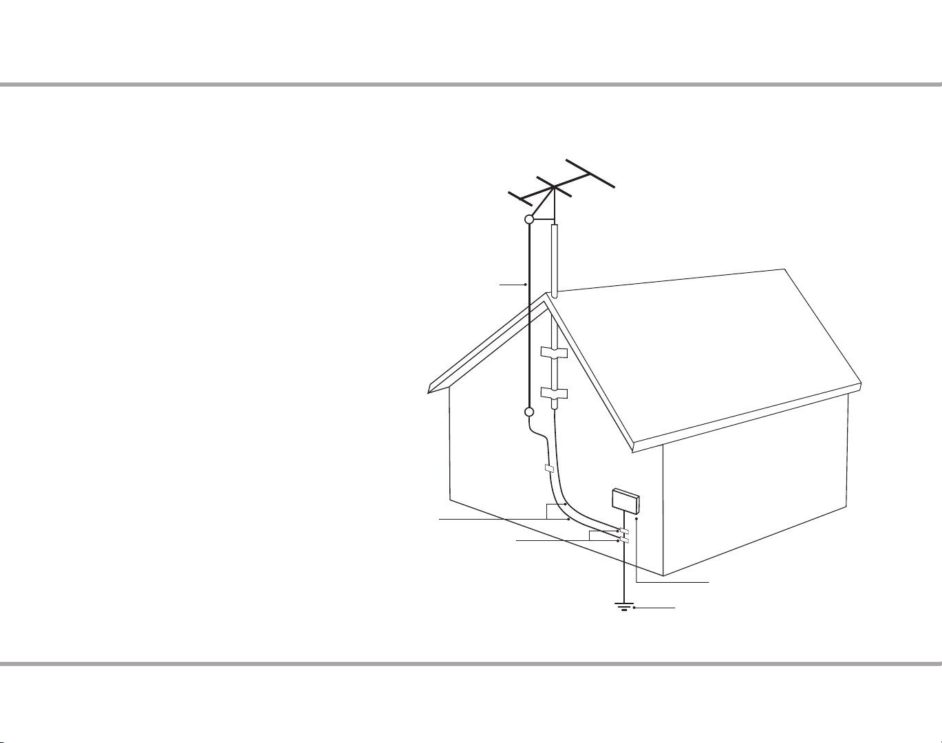
Grounding an Outdoor Antenna
If the AM/FM tuner is used with an outdoor antenna, the antenna must be
grounded against static charges and voltage surges. Consult the instructions
that came with the antenna or contact the antenna manufacturer for proper
installation instructions. The diagram gives a general depiction of how an
outdoor antenna should be grounded. For complete guidelines on antenna
grounding procedures, please consult the National Electrical Code, Section
810, ANSI/NFPA No. 70-1984.
Antenna Lead-In Wire
SAFETY OUTDOOR ANTENNA CONNECTION
Grounding Conductors
Ground Clamps
Electric Service Equipment
Power Service
Grounding Electrode System
Page 4

4 Russound MCA-C5 User and Installation Manual
TABLE OF CONTENTS
Safety Instructions ..................................................................................................................2
Product Overview ...................................................................................................................5
Controller Illustrations ........................................................................................................... 6
Keypad Features ......................................................................................................................8
Keypad Usage ...........................................................................................................................9
Remote Control Illustration ...............................................................................................11
Installation Overview ..........................................................................................................12
Installation Guide ..................................................................................................................13
Keypad Rear Illustration ......................................................................................................14
Keypad IR Connection .........................................................................................................15
Color Plate Conversion ........................................................................................................16
Controller / Keypad Connections ....................................................................................17
Speaker Connections ...........................................................................................................18
Source Connections .............................................................................................................19
IR Connections .......................................................................................................................20
Multiple Controller Installation ........................................................................................21
Trigger Connections .............................................................................................................22
Additional Ports and Antenna Connections ................................................................26
SCS-C5 Conguration Software .......................................................................................27
System Start Up......................................................................................................................28
Remote Control Programming .........................................................................................29
Remote Control Device Codes ..........................................................................................31
Technical specications ......................................................................................................37
Warranty ...................................................................................................................................38
Page 5

5
Russound MCA-C5 User and Installation Manual
Thank you for choosing the Russound MCA-C5 multizone controller amplier
to enhance your home with multiroom audio.
The MCA-C5 caters to homeowners who want control over their multiroom
audio systems with such capabilities as infrared (IR) tools to manage the system
from anywhere in the house. Eight source inputs, simplied programming, and
user adjustable sound controls make listening to music throughout the home
easier than ever.
Key features include:
8 sources delivered to up to 8 zones for sharing music throughout the •
home
Scalable to 48 zones by connecting up to six controllers•
A remote control with simplied programming and control via intelligent •
IR learning capabilities for quick setup
A built-in AM/FM tuner with RDS support•
Line level outputs for each zone•
Eight zone specic 12VDC trigger outputs •
Twelve channels of digital amplication rated at 40 watts per channel for •
zones 1-6
Incorporates RNET smart sources, transmitting metadata (song, artist and •
other information) for display on the keypads
Routed IR source control outputs for each source (1/7 and 2/8 share a •
output), and one common IR output
Party mode, Do Not Disturb, and source / zone linking options•
Alarm clock and sleep timer•
Audio paging with adjustable audio signal sensing and a DC voltage trigger •
input
Source power management with line level auto-sensing•
Front panel USB port for programming ease•
Rear panel RS232 port for integration with other systems•
Conguration software for PC programming •
Supported keypads are the MDK-C5 and the UNO-TS2•
PRODUCT OVERVIEW
Important Note: SCS-C5 software is necessary to program the MCA-C5 system.
It can be downloaded from the Document Center at www.russound.com.
Page 6
6 Russound MCA-C5 User and Installation Manual
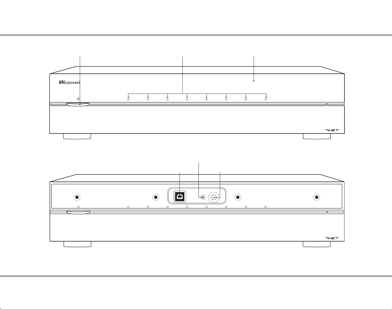
MCA-C5 M ULTIZONE C ONTROLLER
Programming Center
IR In
IR LED
USB
2.0/1.1
MCA-C5 M
ULTIZONE CONTROLLER
CONTROLLER FRONT PANEL
Power Switch
Red LED behind power indicator
USB Port for Programming
Zone LED indicators visible
behind cover
Front Panel
Red IR LED (talk-back)
IR Receiver Window
Removable cover to access IR
window and USB port
Front Panel with cover removed
Page 7
7
Russound MCA-C5 User and Installation Manual
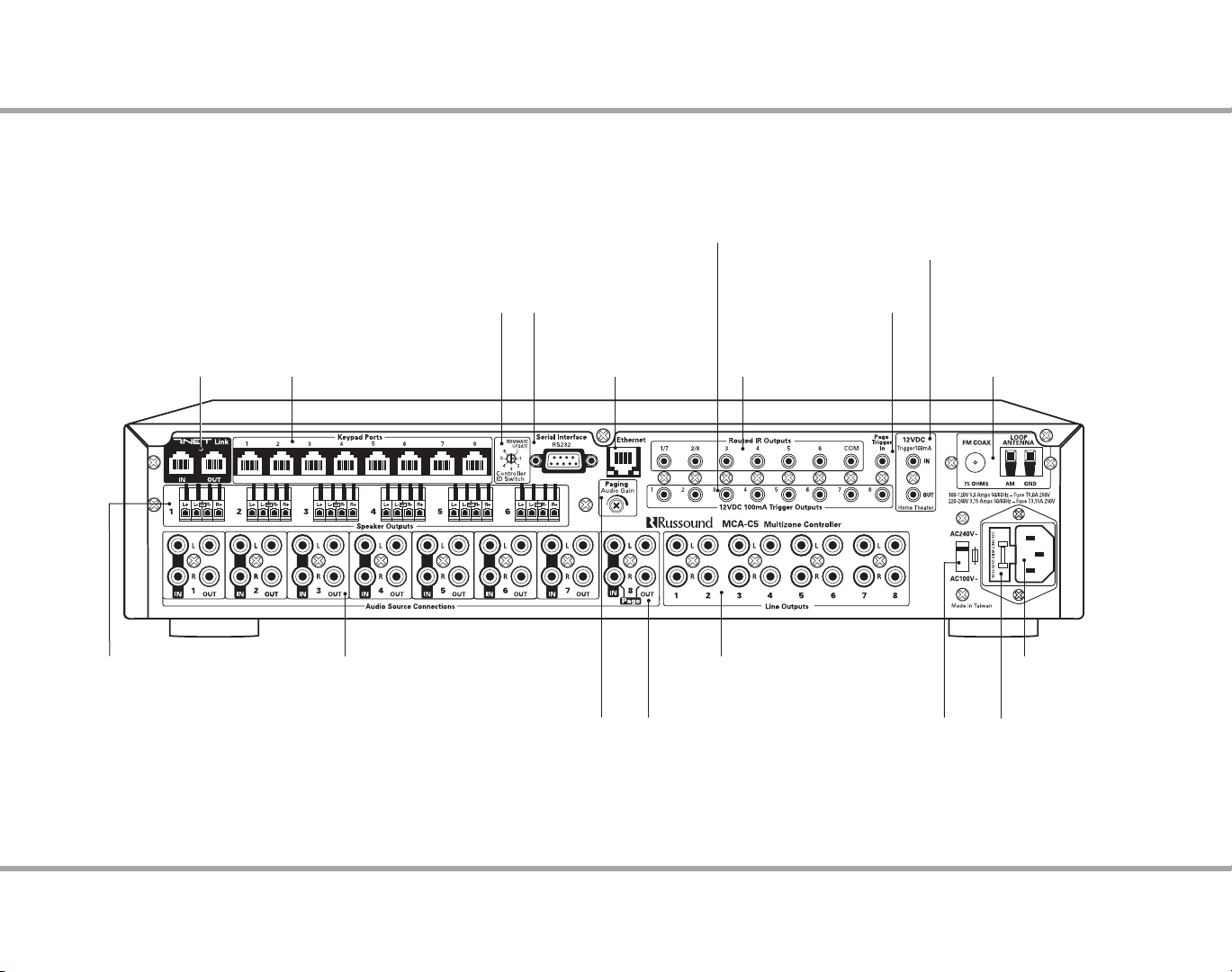
CONTROLLER REAR PANEL
RNET Link - Links
multiple controllers
and RNET sources
Speaker Outputs - Connect
4-8 Ohm speakers for each
of the rst six zones
Controller ID Switch
Set ID for multiple controller
congurations or rmware updates
Keypad Ports - RJ-45
Connections for zone keypads
Audio Source Connections
Signal sensing stereo line level
inputs and loop outputs
12VDC 100ma outputs ready when
corresponding zone is active
Serial Interface
RS232 ports for rmware
updates and communication
Paging Audio Gain
Adjusts sensitivity
Zone 12V Triggers
Ethernet Port
For future use
Page Audio In/Loop Out
(optional Source 8)
Page 12VDC Trigger
Accepts paging device input
IR Outputs
6 routed, 1 common
Line Level Outputs
Can be set xed or variable
(with software) for each zone
AC Voltage Switch
Select appropriate voltage
Home Theater 12 VDC Trigger
Activates source power management
when sharing sources with home
theater
AM/FM Antenna
Antenna connections for
internal tuner
AC 120/240V Input
Detachable grounded
power cord connection
Fuse Holder
Holds replaceable fuse for
AC input connection
Rear Panel
Page 8
8 Russound MCA-C5 User and Installation Manual
KEYPAD FEATURES
OK
VOL
VOL
HOME
MENU
AM/FM
4:30 PM
Now Playing
Home
Shared
Favo rites
Sleep Timer
Alarm
Sources
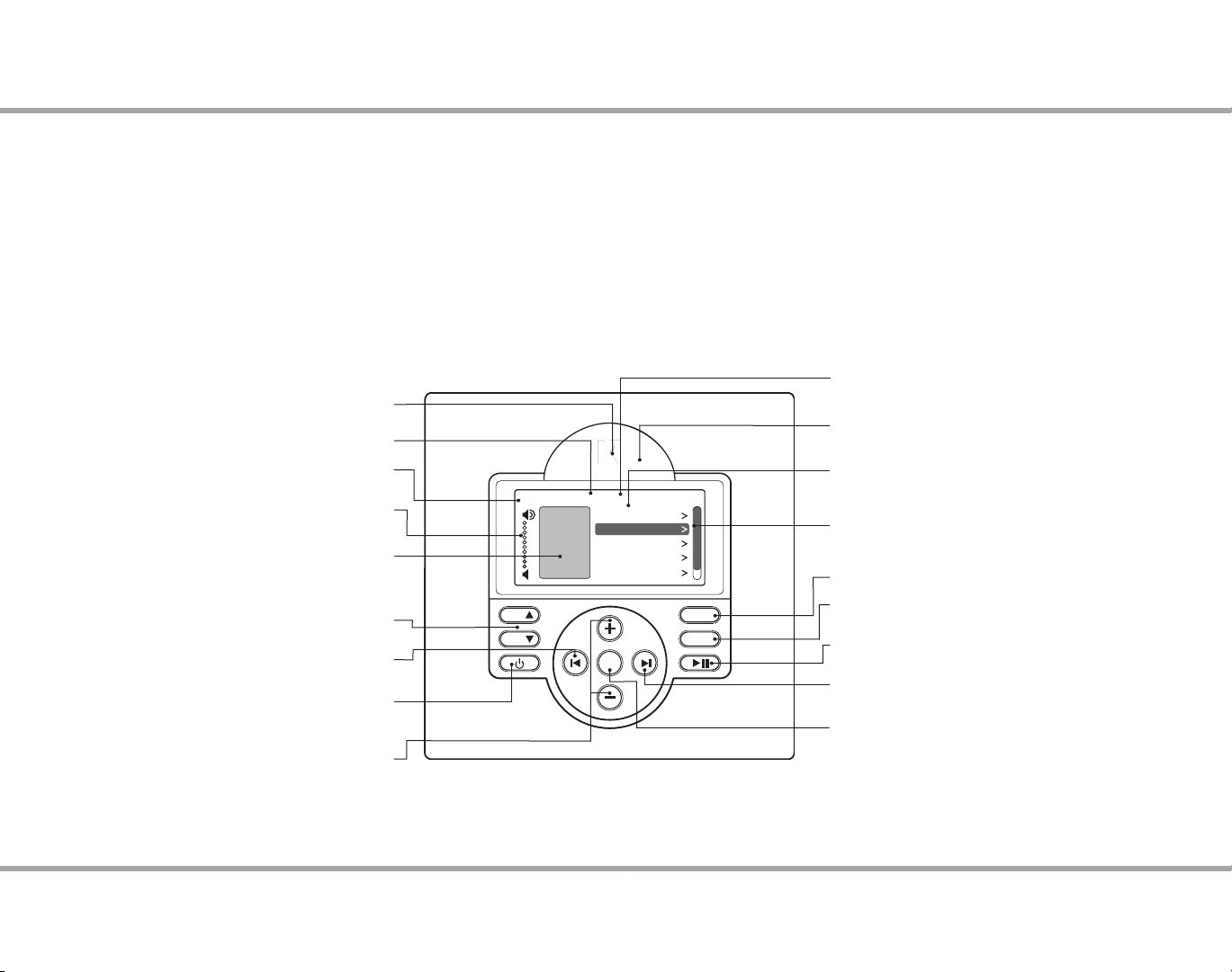
MDK-C5 Keypad
The MDK-C5's buttons and menus allow the user to easily nd and control
music sources and to make changes to system settings and room audio levels.
Six backlit oblong buttons access power on/o, music play/pause, volume
up/down, and menu shortcuts. The OK button in the center activates a menu
choice and the navigation buttons allow you to move through menus and
lists. All music sources, audio adjustments and system settings are arranged
in menus and lists. The navigation buttons also act as source controls to
select next / previous song etc. depending upon the type of source being
controlled.
The keypad’s home screen, buttons and navigation buttons are described
below.
IR Receiver - Receives IR signals from
Title bar - Current menu name
Source name - Shows you what
Volume Indicator - Shows volume
level for the room or if Mute is on
Status box - Shows system status
messages Party, Master, Shared
(source), Do Not Disturb, etc.
Volume - Adjust the volume
Previous - Navigate backwards through
menus or play previous selection
Power - Turn keypad and zone o or on.
Press and hold for system all on/o
Menu Navigation - Navigate through
menus, press (slow) or press and hold
(fast) to move up/down a menu list
the remote control
source you are listening to
up or down
MDK-C5 Keypad Functions
The main menu (Home) options include: Now Playing, Sources, Alarm, Sleep
Timer, Party Mode, Do Not Disturb, and Settings. The Settings menu includes
the audio, clock, display, and installer options. The audio settings include bass,
treble, balance, loudness, and turn on volume.
LCD Screen - Gray scale graphic screen shows
source and system navigation screens
IR Talk-back LED - Lights red to indicate IR
signal receipt
Menu - List of options
to choose from, with
highlighted item selected
Scroll bar - Shows that more menu
choices are available through scrolling
Home - Returns view to the home screen
Menu - Returns view to main menu
(for current source)
Play / Pause - Press for Pause,
or press and hold for Play
Forward - Press to forward through
menu or play next selection
OK - Press to select highlighted item
from the menu, or access source list
from Now Playing
Page 9
9
Russound MCA-C5 User and Installation Manual
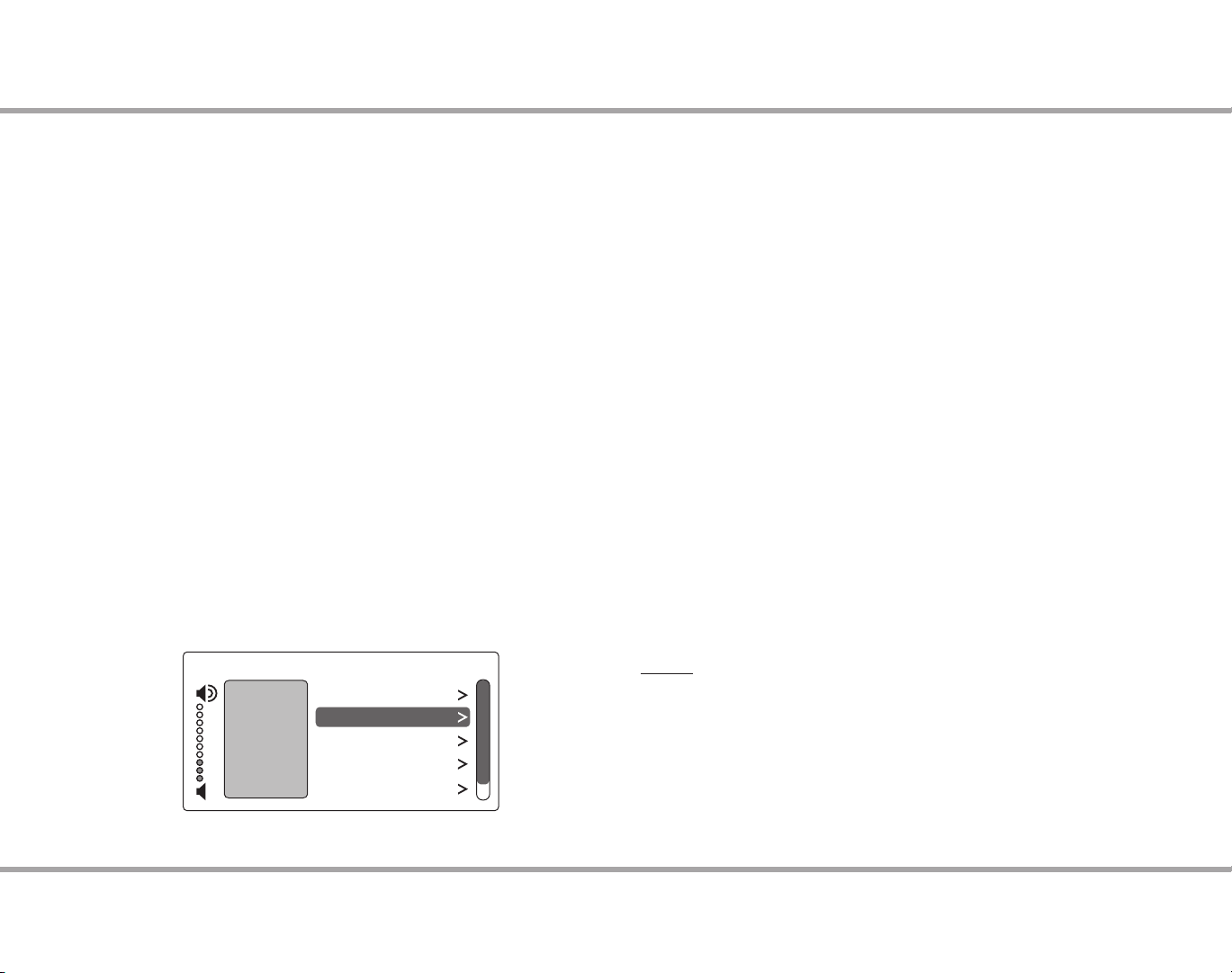
KEYPAD USAGE
AM/FM 4:30 PM
Now Playing
Home
Shared
Favorites
Sleep Timer
Alarm
Sources
Basic Operation
Turn on the zone - Press the power button on the keypad or press power on
the SRC-C5 remote control to turn on the zone and hear music. The zone will
default to the last playing source before being turned o. Press and hold the
power button (when ON) to turn on all the keypads.
Turn o the zone - Press the power button on the keypad or press the power
button on the SRC-C5 remote control to turn o the keypad and music. Press
and hold the power button (when OFF) to turn o all other keypads.
Volume adjustments - Press the Volume up/down buttons on the side of the
keypad, or press the VOL +/- button on the SRC-C5 remote control.
Mute Audio - Press the Mute button on the SRC-C5.
Main Menu - Sources
From the home screen, select "Sources." A list of available audio sources
appears. Select a source, or press a numbered "Source" button on the SRC-C5
remote control.
Once selected, choose music from that source. Each source has its own menu
and screens. Main menus list what is available: channels, genres, playlists,
songs, or artists.
Shared - When you see "Shared" on the screen, what you are listening to is also
playing in another room. If you change the selection (song, channel, playlist)
on that source, the change will also happen in the other "Shared" room.
Main Menu - Favorites
Favorites - Save a source or a radio station/channel as a favorite.
Add new - Tune to the music source you want to save as a favorite. From the
Favorites menu, select "Add New." Name the favorite using the +/- buttons
to move through the alphabet and the forward button to move to the next
character. Press the OK button to save.
Edit name - Choose the favorite to rename and use the +/- buttons to scroll
through the alphabet and the forward button to move to the next character.
Delete favorite - Choose the favorite to be deleted, press the OK button to
delete.
Main Menu - Alarm
Set the keypad as an alarm clock and wake up to music. From the home
screen menu, scroll to and select "Alarm" for the following options:
Alarm on/o - Activates alarm on or o. If an alarm is set a clock icon will
appear on the keypad display.
Wake time - Set the time for the alarm to go o.
Wake to - Choose the music source to wake to.
Choose days - Set the alarm to go o on weekdays, all days or just once.
Set snooze - Choose the interval (5 to 30 minutes) before the alarm goes o
again.
Alarm level - Set the volume of the alarm.
How to:
Turn o active alarm - Press the power button on the keypad or SRC-C5
remote control.
Snooze - Press the pause button on the keypad or the SRC-C5 remote
control.
Page 10
10 Russound MCA-C5 User and Installation Manual
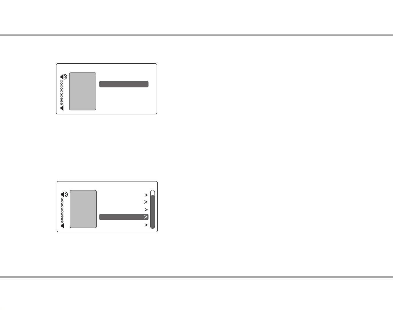
KEYPAD USAGE
AM/FM 7:30 PM
Alarm
Home
Shared
Party Mode
Settings
Sleep Timer
Do Not Disturb
DND
AM/FM
9:30 PM
Sleep Timer
After 15 minutes
Cancel
After 30 minutes
After 45 minutes
After 60 minutes
Main Menu - Sleep Timer
You can set the timer so the zone turns o in one of the following increments:
15, 30, 45, or 60 minutes.
Main Menu - Set Party Mode or Do Not Disturb
Party and Master - The keypad that shows Master has started a "party" and
keypads that show Party are "attending." All rooms are listening to the same
music, and only the Master can change the music. Volume control remains
independent.
Do Not Disturb - Someone in another room has chosen a source and locked
out anyone else from changing it. That room also won’t be disturbed by paging
or a doorbell chime.
Main Menu - Settings
Audio - From the home screen, scroll to and select "settings," and choose
"audio settings." You’ll see items to adjust, such as bass, treble and balance.
Each selection has its own screen and shows levels for real-time adjustments.
Clock
Set Time - From the Clock menu, select "Set Time." Press the +/- buttons to
move through numbers. Press the |< or >| buttons to move the cursor and
press OK to save.
Set Date - From the Clock menu, select "Set Date." The date format is
month/day/year. Press the +/- buttons to move through numbers. Press
the |< or >| buttons to move the cursor, and press OK to save.
Clock Format - From the home menu, select "Settings," then "Clock." Choose
"Clock Format," and select 12 hour (AM/PM) or 24 hour (1200) format.
Display - Set the contrast and brightness for the keypad display. Use the
buttons to move the cursor to the desired level.
Installer Options
IR Enable/Disable - The default is Enabled. If an external IR receiver is used,
the keypad IR receiver should be disabled. From the main menu, select
"Settings," then "Installation," then IR Enable/Disable. Select "disable" and
exit back to the menu.
Diagnostics - The MDK-C5 provides the portal to a support tunnel when an
installer needs Russound’s help troubleshooting an MCA-C5 system. From
the main menu, select "Settings," then "Installation." Choose "Authorize
Support." On the Authorize support screen, select "On." A session number
will be provided in the Session Number box. During the support tunnel
process, the system is unavailable for use.
Page 11
11
Russound MCA-C5 User and Installation Manual
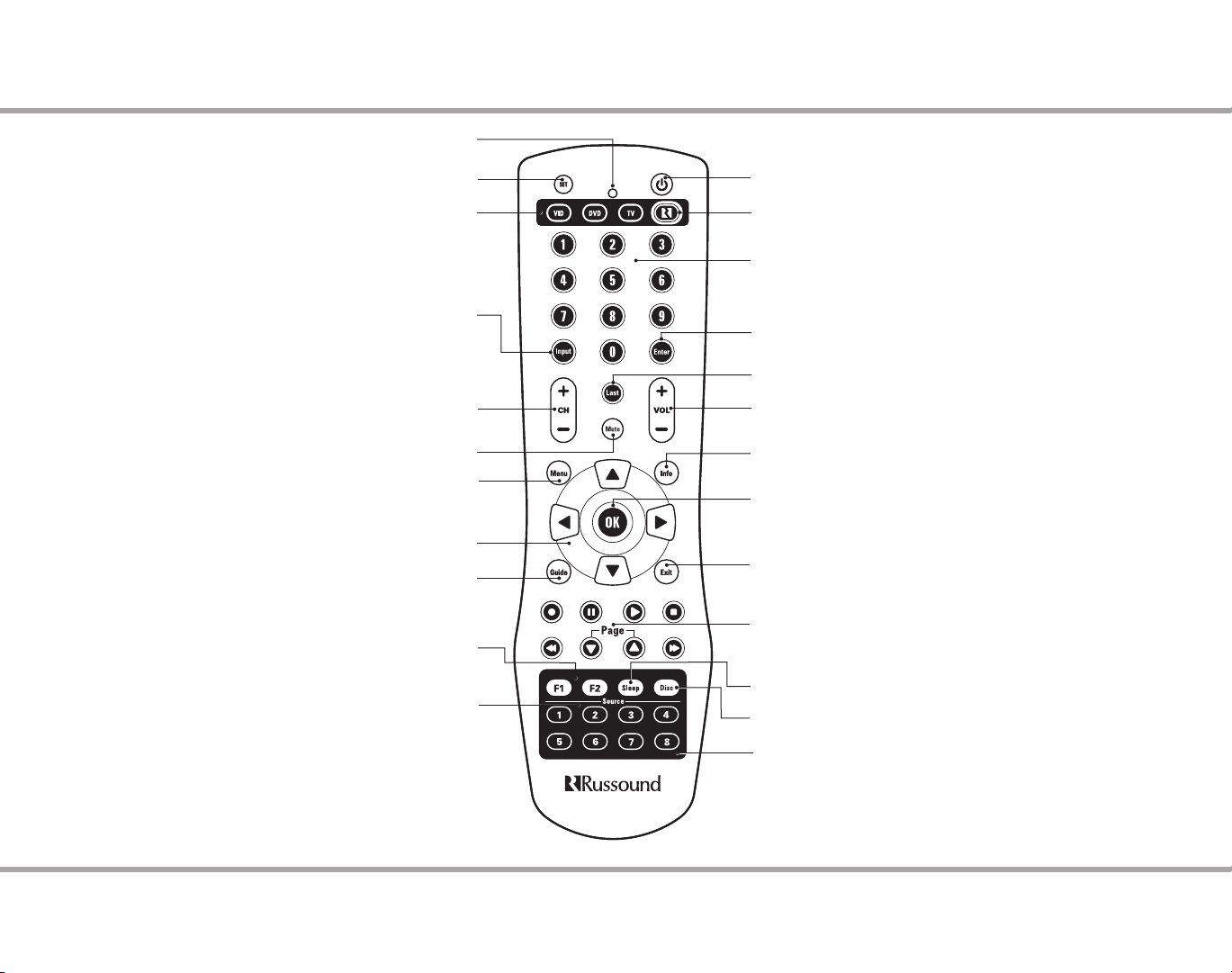
LED - IR Indicator.
SRCC5 REMOTE CONTROL
Set - Program sequences
VID / DVD / TV - Use these keys to select a local device.
Input - Switch the TV’s, VCR’s, SAT’s or DVD’s input
to view TV or video programs.
Without a local device selected, toggles through
sources on keypad.
Channel - Change channels sequentially - up or down.
Mute - Press to turn the sound o or on in the zone.
Menu - Display the menu for the selected device.
Cursor Keys - Move the cursor in the menu screens.
Guide - Display the program guide for the selected device.
Programmable Favorites - Select and save
favorite source or music.
Source Keys - Use these keys to select specic sources on the
keypad and to set which source the remote will control.
Power - Turn the selected source on or o.
Russound Zone Control - Activates control of Russound
system controller and keypads, and its connected sources.
Numeric Keys - Directly enter channels (e.g. 09 or 31).
Enter - Press to choose the highlighted menu option.
May perform “OK" function for devices.
Last - Press to recall the last-viewed channel.
Volume - Raise or lower the sound level of the zone
being controlled.
Info - View the current channel and program information.
OK - Press to choose the highlighted menu
option. May perform “Enter" function for devices.
Exit - Exit the selected device’s menu, guide, or program
without making a menu selection.
Control Keys - Skip backward, rewind, fast
forward, skip forward, record, stop, pause, or play
tracks on source device.
Sleep Timer - Access the sleep timer function on the keypad.
Disc - Direct disc selection on the appropriate device.
Overlays - There are several optional source button overlays
included. Review the source conguration and match the system
programing and source placement to the chosen overlay (if used).
Peel the backing from the rear of the overlay and t it over the
source button block on the SRC-C5 remote.
Page 12
12 Russound MCA-C5 User and Installation Manual
INSTALLATION OVERVIEW
Ventilation Requirements
Important: The MCA-C5 should be situated so that its location or position
does not interfere with its proper ventilation. Do not block vents above or to
the sides of the unit, as it requires ventilation for proper operation. Do not
expose to excessive dust, and do not allow dust to build up on the unit and
block vent holes. Do not place the MCA-C5 above or below a heat-generating
component such as an audio amplier.
Be sure to leave at least 2 inches of space to the sides of the unit with open air
ow above. A single-space rack mount vent or about 1.75 inches must be kept
clear above and below the unit.
Installation
The MCA-C5 controller can be rack mounted or placed on a shelf in an
equipment rack. The controller will occupy two rack spaces with the feet
removed.
The controller can be installed in an equipment rack using the included rackmount ears and hardware to attach the ears to the controller chassis.
Up to six controllers may be connected and allow up to 48 zones on the
system.
Electrical Power
The MCA-C5 operates at 100-120VAC ~60 Hz or 220-240VAC ~50 Hz. Voltage
is selected by the voltage switch on the rear panel and incorporates the
appropriate detachable power cord. It is recommended that the MCA-C5 and
the source equipment be plugged into a dedicated 20-amp circuit. A power
line conditioner can reduce interference problems caused by noise found in
some electrical systems.
The power switch for the unit is on the front panel.
Important Considerations
Disconnect the power cord before making any connections to the •
controller.
Verify that all connections and polarity are correct.•
Keep all power cords away from all signal cables to prevent humming from •
induced noise.
Choose reliable signal cables and patch cords.•
Label all wires with the room location at both ends of the wire.•
Avoid running speaker wires or signal cables close to house electrical •
wiring for any distance. If you have to run them parallel, make sure to space
the wires at least two feet from the AC line. If you need to cross an AC line it
should be at a 90° angle.
For multiple controllers, the controller ID must be set with the rotary switch •
on the rear panel. Each controller must be set to a unique number before
powering connected controllers.
Important: The necessary software (SCS-C5) to program and congure the
system is available via download from the doc center at www.russound.com.
With your laptop, you can congure the system and name all of the zones prior
to connecting with the MCA-C5 controller. See Section on page 27 for items to
be programmed with the software.
Do not connect the controller’s main power feed until all other
connections have been made and veried. Live connection or
removal of the keypad wiring or other wiring when the system
is powered can cause communication problems in the network.
Double-check terminations during each phase of the installation
to prevent accidental damage. Incorrect wiring is the number one
cause for non-warranty product damage.
Page 13

13
Russound MCA-C5 User and Installation Manual
INSTALLATION GUIDE
+
+
Side View
Rack Ear
Front View
Rack Ear
Side View
Rack Ear
Screw Holes
///
/
Wiring
Route CAT-5e cable between the keypad locations and the controller.
Terminate all CAT-5e cables with an RJ-45 connector using the T568A wiring
standard conguration. Utilize a UL/CSA approved electrical box at the keypad
(double-gang at least 32 cu. in.) and controller locations. Using connector
specic wall plates at the controller location will better organize all of the
incoming cables. Route CAT-5e wire from the electrical box to each keypad
location. Label the wires at both ends with the zone and location.
Route standard 4 conductor speaker wire to each speaker location. Each
speaker connection requires a 4-8 ohm load and will provide 40 watts per
channel. Standard 16-gauge 4-conductor stranded speaker wire can be run up
to 125 feet; 14-gauge wire can be run up to 250 feet.
Rack Mount Installation
To attach the rack ears, locate the ve rack mount holes on each side of the
controller’s chassis. Align the holes in the rack ears with the holes in the chassis.
Insert and tighten the screws.
Page 14

14 Russound MCA-C5 User and Installation Manual
KEYPAD REAR
Remove spacers for better t in
Foam Spacer
retrot box or P-ring installations
Cover
Remove to expose
Update port and jumper
External IR Connection
Four pole detachable
screw down connection for
optional external IR receiver
Mounting screws must be hand-
CAUTION
tightened. Over-tightening the
mounting screws can cause the
buttons to jam and malfunction.
Controller
RJ-45 CAT-5e connection to
controller keypad input
OS Update Jumper
Selects "Run" or
"Program" mode
Programming Port
Insert cable here for rmware updates. Requires
Advanced Programming Cable P/N 2500-521065.
MDK-C5 Keypad (rear)
Page 15

15
Russound MCA-C5 User and Installation Manual
External IR Connection to MDK-C5 Keypad
Russound 858
IR Receiver (back)
Shield wired to GND
on keypad only
Do NOT
Connect
Shield
2 Twisted
Pair Cable
AM/FM
11:30 AM
Front IR
On
Off
The MDK-C5 keypad has an External IR Receiver In terminal for connecting an
external IR Receiver such as the Russound 858, SaphIR 862 Eye, or SaphIR 860
Phantom.
Use 2 twisted pair wire with one pair connecting GND (GROUND) and IR
(SIGNAL) and the other pair connecting ST (STATUS) and V+ (+12VDC). Do not
connect the shield to the IR receiver terminals.
If utilizing an external IR receiver, then you must disable the IR receiver in
the keypad. This is disabled in the installer options menu on the keypad. See
screen at right.
KEYPAD IR CONNECTIONS
Disable Keypad IR
Connection of External IR to Keypad
Page 16

16 Russound MCA-C5 User and Installation Manual
VOL
VOL
HOME
MENU
KEYPAD COLOR PLATE CONVERSION
MDK-C5 Color Plate Conversion
You will need both small straight and Phillips head screwdrivers to change
the color plates on the keypad. The Bezel Molding and the Trim Plate will be
switched for the new color plates.
If installed, remove the MDK-C5 keypad from the wall. Gently pull the Trim 1.
Plate o the mounting plate. Unscrew the unit from the electrical box,
and disconnect the cable.
Unscrew the plastic Frame Plate. Keep the Frame Plate and screws for 2.
reattachment later.
Remove the Display Lens from the Bezel Molding by providing inward 3.
pressure to the two locking tabs while simultaneously pushing it away
from the Bezel Molding.
Once the Display Lens is removed, put aside for reattachment later. Be 4.
careful to not damage the display.
Remove the Bezel Molding by gently pressing in each of the 4 locking tabs 5.
(2 per side) while pushing it away from the metal frame.
Reverse the order for installation, taking the following precautions.6.
a. Make sure the button key mat is positioned properly on the front circuit
board and without dust or debris on the button contact points prior to
attaching the Bezel Molding.
b. Make sure that there isn’t any debris or ngerprints on either the display
or back of the Display Lens prior to reattachment.
c. Use a clean, dry, lint-free soft cloth to gently wipe the display or back
of the Display Lens to clean if necessary. Never use cleaning agents as this
can cause streaking or permanent damage to either part.
Screws
Metal Frame
Bezel Molding
Display Lens
Frame Plate
Keypad Disassembly / Assembly
Screws
Trim Plate
Page 17

17
Russound MCA-C5 User and Installation Manual
Controller / Keypad Connection
MDK-C5
MCA-C5 Controller
CAT-5e Cables
MDK-C5
The MDK-C5 keypad is designed for use with the C-Series controllers, and
connects to a keypad port near the top left on the rear of the controller. These
RJ-45 ports support MDK-C5 keypads (and up to two UNO-TS2 touchscreens
per controller).
The eight keypad ports correspond to the eight zones supported by the
MCA-C5. When a connected keypad is powered on, the zone becomes
active and the corresponding zone LED lights up on the front of the MCA-C5
controller.
Connections are made using CAT-5e with RJ-45 connectors using T568A wire
conguration. For a clean installation when wiring from a keypad port use
a CAT-5e patch cable to connect from the keypad port to a RJ-45 wall plate
(optional). Using the same T568A RJ-45 wiring conguration, use CAT-5e cable
from the wall plate to the keypad. Maximum CAT-5e cable length is 250 feet
between the controller and the keypad. The OS Update jumper should be in
the RUN position on the lower two pins.
If more keypads are desired for a zone, use an optional SA-ZX3 keypad
splitter with a Russound 1201A (12VDC 1A) power supply at the controller end.
All keypads on an SA-ZX3 control the same zone. More detailed information
regarding SA-ZX3 installation and operation can be found in its installation
manual.
CONTROLLER / KEYPAD CONNECTION
Keypad connection to the MCA-C5
Page 18

18 Russound MCA-C5 User and Installation Manual
MCA-C5 Controller
Speakers
Speaker Cable
SPEAKER CONNECTIONS
Speaker Output Connections
CAUTION: Do not connect L- and R- together. Use four-conductor cable
and wire each ground individually. Do not use a common ground. Shorting
between terminals will cause damage to the digital amplier.
The MCA-C5 supports speaker outputs for zones 1 through 6. These 40 watt
per channel stereo speaker level outputs have high-current two-channel digital
ampliers. Each speaker connection requires a 4 to 8-ohm load.
The speakers are connected to the MCA-C5 using the supplied modular snap
speaker connectors. Each of these color coded connectors is designated for
the speaker set of a particular amplied zone. To avoid confusion, connect one
zone speaker set at a time starting with Zone 1, taking care to keep zone and
speaker wire identities straight.
Snap Speaker Connector
(detachable)
Strip 1 to 2 inches (2.5 to 5 cm) o the end of each speaker cable jacket. Then
strip ¼ inch (0.7 cm) of insulation o each wire. Twist the speaker wire strands
together so there are no strands separated from the bundle.
Lift the black lever for each connection until it locks open and insert the
proper speaker wire, matching channel and polarity for all four wires. Snap
the lever down. Check to make sure there are no stray strands of wire outside
the terminals. If there are, remove the wire, twist the strands together, and
reconnect the wire to the terminal. Insert the modular connector into its
designated output on the back of the MCA-C5.
All 8 zones have RCA line outs. For audio output to zones 7 and 8, use that
option. These are set as xed or variable output through SCS-C5 software.
Speaker Output Connections
Page 19

19
Russound MCA-C5 User and Installation Manual
SOURCE CONNECTIONS
ST2 Tuner
RS-232
INTERFACE
12VDC 1.25A
I
N OUT
NEWMARKET, NH U.S.A.
ST2
Smart Tuner
LINK KEYPAD PORTS
Serial#
MADE IN KOREA
TUNER 1
FM COAX
LOOP
ANTENNA
IR
LR
A
UDIO OUTPUT
IR
LR
A
UDIO OUTPUT
TUNER 2
FM COAX
LOOP
ANTENNA
MCA-C5 Controller
CAT-5e Cable
RCA cable
CD Changer
MCA-C5 Controller
RNET Source Data Connections
The RNET Link In and Link Out can be used to connect the MCA-C5 to other
specied Russound RNET-enabled source equipment. The connection is made
using a CAT-5e patch cable from the Link Out of the controller and into the Link
In of the RNET-enabled source. Another CAT-5e patch cable can be used to link
out of that source and link into another RNET-enabled source in the system.
Use a standard CAT-5e patch cable with an RJ-45 connector on each end.
Along with RNET data signals, the RNET Link In and Link Out port passes
source IR signals. To avoid potential cross-talk between the source-specic IR
repeating signal lines, the cable can not exceed 18 inches in length.
Source Audio Connections
On the MCA-C5, sources 1 through 8 have standard stereo audio inputs and
loop outputs. All source inputs have audio signal sensing. These sources can
be programmed during zone setup to be global sources, or zones can be
individually programmed to restrict access to sources.
There is an internal AM/FM tuner that, if enabled, will occupy source 1. The
tuner is enabled with the SCS-C5 software. If utilizing the internal tuner, do not
connect/congure another source on source 1.
Connect each source output using quality RCA signal cables. Connect the Left
and Right Audio outputs from each source to the corresponding inputs on the
MCA-C5 controller.
The buered loop-through outputs are used to loop to additional controllers
or other AV switching systems (e.g., home theater receiver).
RNET Source Connection to MCA-C5
Audio Source Connection to MCA-C5
Page 20

20 Russound MCA-C5 User and Installation Manual
IR CONNECTIONS
Media Server
CD Changer
Source 1
IR dual emitter
Russound 1584.1
IR emitter
Russound
845.1
Source 3
Source 7
MCA-C5 Controller
IR Connections
Routed IR Outputs
These six routed IR emitter outputs are supported by the MCA-C5 IR engine
and support IR pass-through. They are also carried by the RNET Link cable to
additional controllers.
Attach the end of the IR emitter with the 3.5mm plug to the IR emitter port.
Remove the adhesive back at the other end of the emitter and attach the
emitter over the source component’s IR window. When using the IR routed
outputs, in order to control this source component with IR, the source must be
selected at the keypad receiving the command.
The six IR routed outputs are designated to the sources as follows: 1/7, 2/8, 3,
4, 5, 6. Two outputs share sources; if you are using routed IR for more than six
sources, use a dual emitter for the two sources that share an IR output.
Note: Since routed outputs 1 and 2 are used for two sources, do not use the
same source type for both sources sharing an IR output.
Common IR
This output is supported by the MCA-C5 IR engine and supports IR passthrough from any of the IR sources or zones. These allow control of any source
equipment without that source being selected on the keypad. The connection
for the common IR output is made using an IR emitter with a 3.5mm plug. The
Russound 845.1 single IR emitter is recommended, or use an IR connecting
block such as the Russound 857 which allows multiple units to be controlled
through a common IR output.
IR Connections to MCA-C5
Page 21

21
Russound MCA-C5 User and Installation Manual
MULTIPLE CONTROLLER INSTALLATION
MCA-C5 Controller (ID#2)
MCA-C5 Controller (ID#1)
CAT-5e Cable
Linking Multiple Controllers
The RNET Link In and Link Out can be used to connect two or more (up to 6)
MCA-C5 controllers (does not support CAV6.6, CAM6.6 or CAA66 controllers).
The connection is made using a CAT-5e patch cable from the Link Out of the
rst controller and into the Link In of the next controller. Along with RNET data
signals, the RNET Link In and Link Out port passes source IR signals.
The CAT-5e patch cable must have an RJ-45 connector on each end with
T568A wiring conguration. It can not exceed 18 inches (45.7 cm) in length
to avoid potential cross-talk between the source-specic IR repeating signal
lines.
Controller ID Switch Settings
The Controller ID switch is a rotary switch with seven positions. It is used to set
the controller ID number for multi-controller systems, and to put the MCA-C5
into Firmware Update mode.
If two or more MCA-C5 controllers are connected using the RNET Link In and
Link Out ports, each controller must have a unique controller ID prior to being
connected through the RNET ports. Set each controller’s ID switch to a unique
number. Any multi-controller conguration requires that one controller be set
to controller ID #1. This action must be performed before the system setup
procedure is completed through SCS-C5 software and before powering up the
system. The small arrow on the dial should point at the desired setting.
Rotate switch to point arrow
to the intended position
Linked Controllers
Page 22

22 Russound MCA-C5 User and Installation Manual
TRIGGER CONNECTIONS
12V trigger cable
R235LS (two-channel amplier)
Speaker cable
Speakers
RCA cable
MCA-C5 Controller
Zone 12VDC Trigger Outputs
There are eight zone 12VDC Triggers which are located under the routed IR
outputs. The 3.5mm mini port provides 12VDC 100mA when the corresponding
zone is turned on and is disengaged when the zone is turned o. The trigger
can be used to engage any 12VDC trigger device or component that does not
exceed 100mA, such as the Russound R235LS amplier. The connections for
the trigger outputs are made using a two-conductor cable with 3.5mm male
mini-plug ports at each end. The tip is positive (+) and sleeve is negative (-).
Typical Amplier Connection
Page 23

23
Russound MCA-C5 User and Installation Manual
Page Trigger IN
Mono RCA
audio cable
Phone system
12VDC trigger cable
MCA-C5 Controller
(optional)
Tip - Pos (+)
Sleeve - Neg (-)
3.5mm Plug
The page trigger can be used to trigger a page event. The 12VDC trigger input
overrides signal sensing and selects the audio input from Source 8 (if included
in page event) and sends it to any zone that does not have page disabled or
that is not in Do Not Disturb mode. Do not use the page trigger input if there is
a regular audio source connected to Source 8.
Note: The diagram at right shows an optional cable to the 12VDC trigger in
from the phone system - this will initiate the page in the event that the volume
or signal is too low initially to activate the line level input.
Paging Audio IN/OUT
The MCA-C5 has a paging audio input and loop output on Source 8 (right
channel only) that accepts line level audio signals via RCA cables. The paging
inputs interface with the page output of a telephone system or other peripheral
device. When a page event is triggered, it interrupts audio outputs for all
enabled zones. System paging can be disabled permanently in each zone by
software programming or temporarily with Do Not Disturb. To utilize Source 8
for paging input, it must be congured as a page source in the SCS-C5 set up.
Note: If Source 8 is enabled for paging events then only seven source inputs
are available.
The audio input has signal sensing for the paging circuit which will indicate
when an audio signal is present. There is a gain control knob above this input
for setting page input sensitivity.
TRIGGER CONNECTIONS
Polarity of 3.5mm Plug
Typical Paging Conguration
(if using source 8 for paging events)
Page 24

24 Russound MCA-C5 User and Installation Manual
TRIGGER CONNECTIONS
Tip - Pos (+)
Sleeve - Neg (-)
3.5mm Plug
Home Theater Triggers
These triggers are used to integrate with home theater systems that can
provide a 12 volt trigger. The MCA-C5 can be used to power manage sources
that are being shared with the home theater system. For example, the power
management system will check to see the state of the home theater before
powering down source gear. Refer to the sample conguration diagram on the
next page for connections.
IN
This 12VDC Trigger input will have dierent functionality based on the state
of the system and the state of the trigger. The connections for the trigger are
made using a two-conductor cable with 3.5mm male mini-plug. The tip is
positive (+) and the sleeve is negative (-).
"System O’ (all zones have been o for at least 5 minutes): If 12VDC is
applied to this input, it will activate the power management ON command to
the sources. While all zones are still OFF and 12VDC is removed, the system will
wait 5 minutes and then activate the power management OFF command to
the sources.
"System On" (at least one zone is on): If 12VDC is present but all zones get
turned OFF, the power management OFF commands will not be sent until 5
minutes after the 12VDC is removed from the trigger.
Note: If the trigger is not being used, power management will operate
normally.
OUT
The 12VDC 100mA trigger out can be used to engage any 12VDC trigger
device or component such as the Russound ACT-1 triggered outlet. The
connections for the trigger out are made using a two-conductor cable with
3.5mm male mini-plug ports at each end. The tip is positive (+) and the sleeve
is negative (-).
The output will be activated when the rst zone is turned on (system on) and
is deactivated six minutes after the last zone is turned o (system o), unless
the home trigger input has 12VDC present.
Polarity of 3.5mm Plug
Page 25

25
Russound MCA-C5 User and Installation Manual
12V trigger cable
Power cord
Power strip
12V trigger cable
Loop to other 12VDC triggered device
120VAC outlet
Power cords
ACT- 1
CD Player
Tuner
DVD
MCA-C5 Controller
Home Theater Receiver
TRIGGER CONNECTIONS
Sample Conguration - Home Theater Trigger
Page 26

26 Russound MCA-C5 User and Installation Manual
ADDITIONAL CONNECTIONS
AM loop antenna
FM antenna
MCA-C5
RS232 Serial Interface
The RS232 serial port is located on the back of the MCA-C5 and use a DB-9
cable connection. The MCA-C5 supports RS232 communication with various
third-party automation systems through the RS232 port. The RS232 port
supports a standard 19.2 kHz baud rate, This port can also used for rmware
updates. Firmware update protocol is available on the Document Center at
www. russound.com.
USB Port
The MCA-C5 has a USB 2.0/1.1 port on the front panel for ease of controller
programming with SCS-C5 software.
Ethernet Port
For future use, the MCA-C5 has a RJ-45 port on the rear panel for connectivity
to the local ethernet network.
AM/FM Antenna Connections:
AM Antenna
Connect the included loop antenna for AM reception to the back panel,
attaching the GND (ground) and AM ends to the appropriate connections. It is
recommended to use an external outdoor or attic-mounted long wire antenna
for best performance for AM reception. Use a 75-ohm to 300-ohm balun at
the AM connection on the controller, and attach the 75-ohm coax cable to the
balun.
FM Antenna
Attach the included FM antenna to the FM COAX connection on the back
panel by pushing the F-type quick-connect termination of the antenna onto
the FM connection. It is recommended to use an external outdoor or atticmounted long wire antenna for best performance for FM reception. Attach
the desired length of 75-ohm coax cable directly to the FM connection on the
controller.
Page 27

27
Russound MCA-C5 User and Installation Manual
Programmable options with SCS-C5 software
The necessary software (SCS-C5) to program and congure the system is
available via download from the Doc Center at www.russound.com. With your
PC laptop, you can congure the system prior to connecting with the MCA-C5
controller. The software has a Source Setup Wizard to aid in the setup and basic
conguration of the sources. Once congured, the system information can be
saved to a le. Reports can also be generated for a hard copy back up of the
system conguration.
Items to be programmed with SCS-C5 software include:
Zone and Source Names - a list of predened names for both are available
and will be visible upon keypads and in reports. Custom naming is also
possible following the character parameters.
Source Exclusion - denes the set of sources available to each zone.
Party Mode Participation - whether the zone can participate in Party
mode.
Zone and Source Linked Groups - Two groups of each type are allowed per
controller. Groups share source selection and party mode participation.
All ON Participation - denes whether or not the zone will respond to the
All ON command.
Page Source - Source 8 can be selected as a page source.
Page Event mode - denes whether a zone will respond to a page event.
Page Volume - sets the volume of a page event in each zone.
Power Management of Sources - enabled / disabled per source. If enabled
the source will turn on when the rst zone is turned on or the home
theater trigger has 12 VDC present. The source will turn o 5 minutes after
the last zone is turned o, or 5 minutes after input is discontinued from
the home theater trigger. This feature uses IR commands and audio signal
sensing to power up sources and initiate audio to conrm source power
states.
Internal AM/FM Tuner on Source 1 - If the tuner is utilized, any input via
the Source 1 input ports on the rear of the unit needs to be disabled.
SCSC5 CONFIGURATION SOFTWARE
Sound Controls - Adjust Bass, Treble, Balance, and Loudness initial settings.
Fixed / Variable Line Output - Determines if zone preamp output gain is at
a xed level or controllable with the zone volume adjustment.
IR Keycode Learning - allows IR codes to be learned, saved, and managed.
Page 28

28 Russound MCA-C5 User and Installation Manual
SYSTEM START UP
Start up
Make connections of sources, speakers and keypads to the controller(s). 1.
In a multiple controller conguration, set the controller IDs to unique 2.
numbers. Use CAT-5e linking cables of no more than 18 in (45.7 cm) to link
the controllers.
Plug in and power the sources and controllers.3.
The left LED showing power on the front panel of each controller should 4.
be lit.
Congure the system using the SCS-C5 software. Load the program onto 5.
Controller#1 using the front USB port.
Check operation of the keypads, power on, and cycle through sources. 6.
The LED should be lit on the front of the controller if the corresponding
keypad is on. The LED will not be lit if the keypad is not turned on or is
absent.
Check operation of all keypad functions. 7.
Check for functional IR signal pass-through (if applicable). 8.
The system is now ready to use.9.
Troubleshooting
When the controller and the keypads are powered ON all the corresponding •
LEDs on the face of the controller will be green. Improper connection may
cause one or more LEDs not to be lit. Check all connections.
Cycle power by pressing the power button, waiting 10 seconds, and then •
pressing the power button again.
Check connections from the keypads and speakers to the controller(s).•
If the keypad doesn't respond to commands ensure the OS update jumper •
on the rear of the keypad is in the RUN position (on the lower pins).
Page 29

29
Russound MCA-C5 User and Installation Manual
SRCC5 REMOTE CONTROL PROGRAMMING
Programming a Device
To control Universal TV, VCR or DVD, Cable or Satellite Receivers, Amplier or
tuner, and Auxiliary devices, follow these steps. Before proceeding, nd the
codes for the devices you want to program in "Manufacturer’s Codes" in this
manual.
Turn on the device (e.g., DVD player) and if needed, load media.1.
Press a device key.2.
Press and hold SET until the red LED blinks twice, then release.3.
Enter the rst ve-digit code for your device. The LED blinks once as each digit is 4.
entered. If the code is correct, the LED blinks twice.
Note: If the LED does not blink twice, repeat step 4 and try entering the code again.
Aim the remote at the device and press POWER. The device should turn o. If it does 5.
not, repeat steps 3-5, trying each code for your brand until you nd one that works.
If you cannot nd a code that works see "Searching for Your Code" in this manual.
Repeat steps 1-5 for the other devices you want to control. For future reference, 6.
write down each working device code.
Set - Press and Hold until
LED ashes appropriately
LED - ashes indicating programming and talkback
Power - Controls Zone or
Source On/O
Source - Selects local
source or RNET controls
Numeric Keypad - Enter IR
codes and numeric input
Searching for your Code
If your device does not respond to the remote after trying all codes listed for
our brand, or if your brand is not listed, try searching for your code:
Press a device key once.1.
Press and hold SET until the red LED blinks twice, then release.2.
Enter 9-9-1, then the device group number (see below). The LED blinks twice.3.
0 Cable (Cable Converters, Video Accessories, Satellite Receivers)
1 TV (TVs)
2 VCR (VCRs, DVD players)
3 Audio (Audio Ampliers, Audio Amp/Tuners, CD players)
Aim the remote at the device and press POWER. The remote sends IR codes from its 4.
library to the selected device, starting with the most popular code rst. If the device
responds, go to step 6.
If the device does not respond, press CH+. the remote will try the next code. 5.
Continue until the device responds. Press CH- to try the previous code.
Press SET to lock in code. To search for other device codes, repeat steps 1-5. 6.
Checking the Codes
If you have set up the remote using the procedure in "Searching for Your
Code," you may need to nd out which ve-digit code is operating your
equipment. For example, to nd out which code is assigned to your TV:
Press the key to which the TV is assigned.1.
Press and hold SET until the red LED blinks twice, then release.2.
Enter 9-9-0. The LED blinks twice.3.
To view the code’s rst digit, press 1. Count the LED blinks (e.g., three blinks =3), and 4.
enter the number in the appropriate device list in step 8 of "Programming a Device."
If a code digit is 0, the LED does not blink.
Repeat step 4 for the remaining digits, using 2 for the second digit, and so on.5.
To check for other device codes, repeat steps 1-5, using the appropriate key.6.
Remote Control Programming Keys
Page 30

30 Russound MCA-C5 User and Installation Manual
REMOTE CONTROL PROGRAMMING
Using Learning
The SRC-C5 includes a Learning feature so you can add functions that are unique
to your home entertainment devices (e.g., VCR Tracking Up or Down). The following
precautions apply:
The original remote control must be in working order and available for learning to •
work properly.
Learned keys are mode specic, so each one can store a unique function for each •
mode.
Do not use the following keys for learning: Device Keys, SET, Back, or Record.•
Learning capacity is approximately 40 to 100 keys, depending on the code being •
learned.
Certain device codes are not learnable including multi-frequency types, some high •
frequency ones, and other unusual formats.
For optimum learning, avoid high levels of ambient light such as natural sunlight or •
energy-ecient uorescent lights.
Programming a learned key
Note: If more than 15 seconds pass between key presses, the remote exits programming.
Press and hold SET until LED ashes twice.1.
Press 9-7-5.2.
Press a device key once to assign a mode for learning.3.
Place the SRC-C5 head-to-head (about 2" apart) from your original remote control. 4.
Also locate the key (on original remote control) that will serve as the teaching
function.
On the SRC-C5, press a key where the learned function will be stored.5.
On the original remote, press and hold the the key to be learned. The SRC-C5 LED 6.
will turn o. Continue holding the key on the original remote until the SRC-C5 LED
blinks twice.
Note: If the LED displays one long blink, a learning error has occurred. Try repeating
this step again until a successful capture occurs. If the function is still not captured,
press and hold SET to exit programming. Review the learning precautions listed
above, or the Troubleshooting tips below, before beginning again at step 1.
Repeat steps 4-6 for another key on same device, or repeat steps 1-6 for another 7.
device.
Deleting a single learning key
Select a source.1.
Press and hold SET until the LED ashes twice.2.
Press 9-7-6.3.
Press the key (twice) containing the learned function to be deleted. The remote 4.
blinks twice.
Repeat steps 1-4 for another key on the same source, or press and hold SET to exit 5.
programming.
Deleting all learned keys in a specic mode
Press and hold SET until the LED blinks twice.1.
Press 9-7-6.2.
Press a device key twice to delete all the learned keys for that mode. The LED blinks 3.
twice.
Repeat steps 1-3 for another set of keys for a device, or press and hold SET to exit 4.
programming.
Changing Volume Lock
The SRC-C5 remote is preset to allow independent volume control of each selected
device (Global Volume Unlock). However, you may change the Volume Lock setting to
Global Volume Lock so that one device’s volume will control volume in all other modes.
After that, you can perform Individual Volume Unlock on a selected device to set its
volume control for independent operation or Global Volume Unlock to remove all
volume locking.
Locking Volume Control to One Mode (Global Volume Lock)
Press and hold SET until the red LED blinks twice, then release. 1.
Enter 9-9-3 and then press the mode key for the device you want to control volume 2.
(e.g., TV). The LED blinks twice. Now when you press VOL+, VOL-, or Mute, the
selected device will control the volume regardless of the current mode.
Unlocking All Volume Control (Restoring Global Unlock)
Press and hold SET until the red LED blinks twice, then release.1.
Enter 9-9-3 and then press VOL+. The LED blinks four times. Volume is independently 2.
controlled for all programmed devices.
Unlocking a Single Device’s Volume Control
Press a device key (VID, DVD, etc.).1.
Press and hold SET until the red LED blinks twice, then release.2.
Enter 9-9-3 and then press VOL-. The LED blinks four times. Volume is independently 3.
controlled for the selected devices.
Page 31

31
Russound MCA-C5 User and Installation Manual
MANUFACTURER’s CODES
Setup Codes for Audio Ampliers
Accuphase 30382
Acurus 30765
Adcom 30577, 31100
Aragon 30765
AudioSource 30011
Bel Canto Design 31583
Bose 30674
Carver 30892
Curtis Mathes 30300
Durabrand 31561
GE 30078
Harman/Kardon 30892
JVC 30331
Kenwood 30356
Klipsch 30765
Left Coast 30892
Lenoxx 31561
Luxman 30165
Marantz 30321, 30892
Mark Levinson 31483
Mondial 30765
Nakamichi 30321
NEC 30264
Optimus 30300, 30395
Parasound 30246
Philips 30892
Pioneer 30013, 30300
Polk Audio 30892
PS Audio 31523
RCA 30300
Realistic 30395
Sansui 30321
Shure 30264
Sony 30689, 30815
Soundesign 30078, 30211
Victor 30331
Wards 30013, 30078, 30211
Yamaha 30133, 30143, 30354, 30504
YBA 31502
Setup Codes for Audio Amp/Tuners
ADC 30531
Adcom 30616, 31616, 31617
Aiwa 30121, 30158, 30189, 30405, 31089,
Akai 30076, 30224, 31255, 31512
Alco 31390
AMC 31077
Amphion Media Works 31563, 31615
Amplifier Technologies 31584
31243, 31321, 31347, 31388, 31405,
31641
AMW 31563, 31615
Anam 31074, 31609
Apex Digital 31257, 31430
Arcam 31120, 31189
Atlantic Technology 31487
Audiophase 31387
Audiotronic 31189
Audiovox 31390, 31627
Bel Canto Design 31584
Bose 30639, 31229, 31253
Brix 31602
Cambridge Soundworks 31370, 31477
Capetronic 30531
Carver 30008, 30042, 30121, 30189, 30360,
31089, 31189, 31289
Casio 30195
Clarinette 30195
Classic 31352
Coby 31263, 31389, 31513
Compaq 31136
Criterion 31420
Curtis 30797, 31596
Curtis Mathes 30080
Daewoo 31250
Dell 31383
Denon 30004, 30121, 30273, 30771, 31104,
Emerson 30255, 30424
Fisher 30042, 30219, 30360, 31409, 31801
Fosgate 31487
Garrard 30146, 30281, 30424, 30440, 30463
Gateway 31517, 31567
GE 31379
Glory Horse 31263
Go Video 31352, 31532
GoldStar 30281
GPX 31299
Hafler 30146
Harman/Kardon 30110, 30189, 30891, 31289, 31306
Hewlett Packard 31181
Hitachi 31273, 31801
Initial 31426
Inkel 30062
Integra 30135, 31298
JBL 30110, 31306
JVC 30074, 31058, 31263, 31282, 31374,
31495
Kansai 30440
Kenwood 30027, 30042, 30077, 30186, 30239,
KLH 31390, 31412, 31428
Koss 30255, 30424, 31366, 31497
Lasonic 31510, 31798
Lenoxx 31437
31142, 31311, 31360, 30023, 30302
30313, 30314, 30569, 31027, 31051,
31052, 31313, 31569, 31570
Lexicon 31076
LG 30281, 31293
Linn 30189
Liquid Video 31497
Lloyd’s 30195
LXI 30181
Magnavox 30128, 30189, 30195, 30391, 30531,
Marantz 30039, 30128, 30189, 30200, 31089,
31189, 31269, 31289
McIntosh 31289
MCS 30039, 30346
Memorex 31596
Micromega 31189
Mitsubishi 31393
Modulaire 30195
Musicmagic 31089
Myryad 31189
NAD 30320
Nakamichi 30097, 30347, 31313, 31555
NEC 30235
Norcent 31389
Nova 31389
Onkyo 30135, 30380, 30842, 31298, 31531
Optimus 30042, 30080, 30177, 30181, 30186,
Oritron 31366, 31497
Outlaw 31487
Outlaw Audio 31487
Panasonic 30039, 30309, 30367, 30518, 31288,
Penney 30195
Philips 30189, 30391, 31089, 31120, 31189,
Pioneer 30014, 30080, 30150, 30244, 30531,
Polaroid 31508
Polk Audio 30189, 31289
Proscan 31254
Quasar 30039
RadioShack 31263
RCA 30054, 30080, 30346, 30360, 30530,
Realistic 30163, 30181, 30195
Regent 31437
Rio 31383, 31869
Rio Audio 31383
Saba 31519
Samsung 31295, 31500
Sansui 30189, 30193, 30346, 31089, 31189,
Sanyo 30219, 30801, 31251, 31469, 31801
SRCC5 REMOTE CONTROL DEVICE CODES
31089, 31189, 31269, 31514
30219, 30440, 30531, 30670, 30738,
30797, 30801, 30849, 31023, 31074
31308, 31316, 31350, 31363, 31509,
31518, 31548, 31633, 31763, 31764
31266, 31268, 31269, 31283, 31365,
31368
30630, 30801, 31023, 31084, 31184,
31343, 31384
30531, 31023, 31074, 31154, 31254,
31390, 31511, 31609
31764
Scott 30163, 30322
Sharp 3 0186, 30771, 31286, 31361, 31386
Sharper Image 30797, 31263, 31385, 31409, 31410,
Sherwood 30062, 30491, 30502, 31077, 31423,
Shinsonic 31426
Sirius 31602, 31627
Sonic 30281
Sonic Blue 31383, 31532, 31869
Sony 30158, 30168, 31042, 31058, 31131,
Soundesign 30670
Stereophonics 31023
Sunfire 30313, 30314, 31052, 31313
Sylvania 30797
Teac 30163, 30463, 31074, 31267, 31390,
Technics 30039, 30208, 30309, 30518, 31308,
Techwood 30281
Thorens 31189
Toshiba 30080, 30135
Venturer 30849, 31390
Victor 30074
Wards 30014, 30054, 30080, 30158, 30189
XM 31406
Yamaha 30081, 30176, 30186, 31176, 31276,
Yorx 30195
Zenith 30281, 30857, 31293
31411, 31416, 31545, 31546, 31549,
31556, 31723
31517, 31567, 31653
31158, 31258, 31347, 31349, 31367,
31371, 31382, 31406, 31441, 31442,
31458, 31503, 31529, 31558, 31658,
31758, 31759, 31858
31528
31309, 31384, 31518, 31633
31331, 31375
Setup Codes for Cable Converters
ABC 00001, 00003, 00007, 00008, 00011,
Allegro 00153, 00315
Americast 00899
Antronix 00022, 00207
Archer 00022, 00153, 00207, 00797
Belcor 00056
Bell & Howell 00014
Bell South 00899
Cable Star 00056
Cabletenna 00022
Cableview 00022
Century 00153
Citizen 00153, 00315
Clearmaster 00883
ClearMax 00883
Cleartron 01327
Colour Voice 00025, 00031
00013, 00014, 00017
Page 32

32 Russound MCA-C5 User and Installation Manual
SRCC5 REMOTE CONTROL DEVICE CODES
Setup Codes for Cable Converters
(continued)
Comtronics 00040
Contec 00019
Coolmax 00883
Digi 00637
Director 00476
Dumont 00637
Eastern 00002
Emerson 00797
Everquest 00015, 00040
Focus 00400
Garrard 00153
GC Electronics 00056, 00207
Gemini 00015, 00797
General Instrument 00003, 00011, 00276, 00476, 00810
Global 01327
GoldStar 00040, 00144
Goodmind 00797
Hamlin 00009, 00020, 00034, 00259, 00273
Hitachi 00011
Hytex 00007
Jasco 00015, 00153, 00315
Jerrold 00003, 00011, 00012, 00014, 00015,
00276, 00476, 00810
Linsay 00440
Magnavox 00027
Memorex 00000
Motorola 00014, 00276, 00476, 00810, 01106,
Movie Time 00063, 00156
Multitech 00883
Novaplex 00618
NSC 00063, 00156
Oak 00007, 00019
Optimus 00021
Pace 00008, 00237, 01877
Panasonic 00000, 00021, 00107
Panther 00637
Paragon 00000
Philips 00025, 00027, 00031, 00153, 00317,
Pioneer 00144, 00533, 00877, 01021, 01877
Popular Mechanics 00400
Pulsar 00000
Quasar 00000
RadioShack 00015, 00315, 00797, 00883
RCA 00021
Realistic 00207
Recoton 00400
Regal 00020, 00259, 00273, 00279
Regency 00002
Rembrandt 00011
Runco 00000
Samsung 00040, 00144
01254, 01376
01305
Scientific Atlanta 00008, 00017, 00477, 00877, 01877
Seam 00510
Signal 00015, 00040
Signature 00011
SL Marx 00040
Sony 01006
Sprucer 00021
Starcom 00003, 00015
Stargate 00015, 00040, 00797
Starquest 00015
Supercable 00276
Supermax 00883
Sylvania 00001
Tandy 00258
Teleview 00040
Texscan 00001
TFC 00310
Time Warner Cable 01877
Timeless 00040
Tocom 00012, 00013
Torx 00003
Toshiba 00000
Tristar 00883
Tusa 00015
TV86 00063
Unika 00022, 00153, 00207
United Artists 00007
Universal 00022, 00056, 00153, 00191, 00207
V2 00883
Viewmaster 00883
Viewstar 00027, 00063, 00258
Vision 00883
Vortex View 00883
Zenith 00000, 00525, 00899
Zentek 00400
Setup Codes for CD Players
ADC 30018
Adcom 30155, 30234
Aiwa 30012, 30124, 30157
Akai 30156
Arcam 30157
Audio Alchemy 30194
Audio-Technica 30170
BSR 30194, 30245
Burmester 30420
California Audio Labs 30029, 30303
Carrera 30194
Carver 30157, 30179, 30437
Classic 31297
Crown 30122
DAK 30245
DBX 30254
Denon 30003, 30626, 30873
DKK 30000
DMX Electronics 30157
Emerson 30155, 30164, 30305, 30469
Fisher 30088, 30174, 30179, 30342, 31325
Garrard 30245, 30280, 30393, 30420, 30425
GE 30009
Gemini 30625
Genexxa 30032, 30164, 30305
GoldStar 30417, 31208
GPX 31296
Harman/Kardon 30157, 30173, 30426, 31202
Hitachi 30032, 30155
Integra 30101
JVC 30072, 30655, 31294
Kenwood 3 0028, 30037, 30190, 30626, 30681, 30826
KLH 31318
Kodak 30287
Koss 31317
Krell 30157
Kyocera 30018
LG 31208
Linn 30157
Luxman 30093
LXI 30305
Magnavox 30157, 30305
Marantz 30029, 30157, 30180, 30626
Mark Levinson 31484
McIntosh 30287
MCS 30029, 30043
Miro 30000
Mission 30157
MTC 30420, 30625
Nakamichi 30147
NEC 30043, 30234
Nikko 30164, 30170, 30174, 30625
NSM 30157
Onkyo 30101, 30868
Optimus 30000, 30032, 30037, 30087, 30145,
Panasonic 30029, 30303, 30752
Parasound 30194, 30420
Philips 30157, 30287, 30626
Pioneer 30032, 30305, 30468, 31062, 31063,
Polk Audio 30157
Proceed 30420
Proton 30157
QED 30157
Quad 30157
Quasar 30029
RadioShack 31075
RCA 30009, 30032, 30053, 30155, 30179,
Realistic 30155, 30164, 30175, 30179, 30180,
30175, 30179, 30194, 30196, 30280,
30305, 30342, 30420, 30426, 30437,
30468, 31063, 31075
31087
30305, 30420, 30468, 30764, 31062
30420
Rotel 30157, 30420
SAE 30157
Sansui 30157, 30202, 30305
Sanyo 30087, 30179
Scott 30155, 30164, 30305
Sears 30305
Sharp 30037, 30180, 30861
Sherwood 30180, 30196, 30426, 31067
Shure 30043
Simaudio 30157
Sonic Frontiers 30157
Sony 30000, 30100, 30185, 30490, 30604,
Soundesign 30145, 30425
STS 30018
Sugden 30157
Symphonic 30305
TAG McLaren 30157
Tascam 30420
TDK 31208
Teac 30174, 30180, 30393, 30420
Technics 30029, 30207, 30303
Tivoli Audio 31553
Vector Research 30194, 30417
Victor 30072
Wards 30053, 30157
Yamaha 30036, 30170, 30187, 30490, 30888,
YBA 30625
Yorx 30461
30605, 31364
31292
Setup Codes for Video Accessories
ABS 01272
Alienware 01272
CyberPower 01272
Gateway 01272
Hewlett Packard 01267, 01272
Howard Computers 01272
HP 01272
Hush 01272
iBUYPOWER 01272
InterVideo 01393
Jensen 01165
JVC 01384
Keyspan 01344
KWorld 01403
LG 01415
Linksys 01272, 01365
Macro Image Technology 01383
Media Center PC 01272
Microsoft 01272
Mind 01272
Motorola 01363
MyHD 01383
Niveus Media 01272
Page 33

33
Russound MCA-C5 User and Installation Manual
Setup Codes for Video Accessories
(continued)
Northgate 01272
Panasonic 01120
Pinnacle Systems 01268
Pioneer 01010
Princeton 00113, 00295
Rabbit 00081
Ricavision 01272
Roku 01486
Samsung 01190, 01490
Sensory Science 01126
Sharp 01010
SMC 01456
Sony 01272, 01324, 01364
Stack 9 01272
Streamzap 01309
Systemax 01272
Tagar Systems 01272
TeleCaption 00171
Toshiba 01272
Touch 01272
Viewsonic 01272, 01329
Vizio 01126
Voodoo 01272
ZT Group 01272
Setup Codes for DVD Players
Adcom 21094
Advent 21016
Aiwa 20641, 21912
Akai 20695, 20770, 20899, 21089, 21975
Allegro 20869
Amphion Media Works 20872, 21176, 22001, 22016
AMW 20872, 21176, 22001, 22016
Anam 21913
Apex Digital 20672, 20717, 20755, 20794, 20796,
Aspire Digital 21168
Audiologic 20736
Audiovox 20717, 21041, 21071, 21072, 21121,
Axion 21071, 21072
B & K 20655, 20662
Bel Canto Design 21571
Blaupunkt 20717
Blue Parade 20571
Broksonic 20695, 20868
Byd:sign 20872
California Audio Labs 20490
Cambridge Soundworks 21916
CAVS 21057
CineVision 20833, 20869, 20876
Classic 21917
20797, 20830, 21004, 21020, 21056,
21061, 21100, 21915, 21937
21122
Coby 20778, 20852, 21086, 21107, 21165,
Criterion 22007
Curtis Mathes 21087
CyberHome 20816, 21023, 21024, 21117, 21129
Daewoo 20705, 20784, 20833, 20869, 21172,
Daytek 20872
Denon 20490, 20634
Disney 20675
Dual 21068, 21085
DVD2000 20521
Emerson 20591, 20675, 20821
Enterprise 20591
Fisher 20670, 21919
Funai 20675
Gateway 21073, 21077, 21158
GE 20522, 20717, 20815
General Electric 20717
Go Video 20715, 20744, 20783, 20833, 20869,
Go Vision 21071, 21072
GPX 20699, 20769
Gradiente 20490
Greenhill 20717
Grundig 20539
Harman/Kardon 20582, 20702
Hitachi 20573, 20664, 21919
Hiteker 20672
Initial 20717, 21931
Integra 20571, 20627, 21924
Jamo 22003
Jaton 21078
JBL 20702, 21926
Jensen 21016
JVC 20558, 20623, 20867, 21901, 21940
jWin 21049, 21051
Kenwood 20490, 20534, 20682, 21063
KLH 20717, 21020, 21149, 21939
KLH Digital 20717
Konka 20711, 20719, 20720, 20721
Koss 20651, 21980
Landel 20826
Lasonic 20798, 21173
Lecson 21533
Lenoxx 21938
LG 20591, 20801, 20869, 21906
Liquid Video 21980
LiteOn 21058, 21158
Loewe 20511
Magnasonic 20651, 20769
Magnavox 20503, 20539, 20646, 20675, 20821,
Malata 20782, 21159
Marantz 20539
21923
21918
21044, 21075, 21099, 21144, 21158,
21730, 21970
21914, 21976
McIntosh 21533
Memorex 20695
Microsoft 20522
Mintek 20717, 20839, 21990
Mitsubishi 20521, 21521
Momitsu 21082
NAD 20591, 20692
NEC 20785
Nesa 20717
Next Base 20826
Niro 22024
Norcent 20872, 21003, 21107, 21923
Nova 21923
Onkyo 20503, 20627, 20792, 21924, 21985
Orion 20695
Oritron 20651, 21980
Panasonic 20490, 20503, 20632, 21362, 21462,
Philco 22000
Philips 20503, 20539, 20646, 20675, 20854,
PianoDisc 21024
Pioneer 20525, 20571, 20631, 20632, 20638,
Polaroid 21020, 21061, 21086, 21200, 21998
Polk Audio 20539
Portland 20770
Presidian 20675
Prima 21016
Princeton 20674
Proceed 20672
Proscan 20522
ProVision 20778
Qwestar 20651
RCA 20522, 20571, 20717, 20822, 21022,
Regent 21938
Rio 20869, 22002
Rotel 20623
Rowa 20823
Saba 21977
Sampo 20698, 20752
Samsung 20490, 20573, 20744, 20820, 20899,
Sansui 20695
Sanyo 20670, 20695, 20873, 21919, 21967
Sensory Science 21158
Sharp 20630, 20675, 20752
Sharper Image 21117, 21995
Sherwood 20633, 20770, 21043, 21077
Shinsonic 20533, 20839, 21931
Sigma Designs 20674
Sonic Blue 20869, 21099, 21970, 22002
Sony 20533, 20772, 20864, 21033, 21533,
SRCC5 REMOTE CONTROL DEVICE CODES
21490, 21762, 21907, 21908, 21909,
21910, 21925, 21986, 21990, 22017
21914, 20885
21571, 21902, 21965
21132, 21193, 21913, 21965, 21974
21044, 21075, 21932, 21979
21903, 21904, 21934, 21981, 22020
Sova 21122
Sungale 21074
Superscan 20821
SVA 20860, 21105
Sylvania 20630, 20675, 20821
Symphonic 20675
Teac 20717, 20809, 21984
Technics 20490
Technosonic 20730
Techwood 20692
Terapin 21031
Theta Digital 20571
Tivo 21996
Toshiba 20503, 20695, 21045, 21154, 22006,
Tredex 20799, 20800, 20803, 20804
Urban Concepts 20503
US Logic 20839
V 21064
Vizio 21064, 21226
Vocopro 21027
Xbox 20522
Xwave 21001
Yamaha 20490, 20539, 20545
Yamakawa 20872
Zenith 20503, 20591, 20869, 21906
21988, 21996
Setup Codes for Satellite Receivers
AlphaStar 00772
Chaparral 00216
Crossdigital 01109
DirecTV 00099, 00247, 00392, 00566, 00639,
Dish Network 00775
Dish Network System 00775, 01005, 01170, 01505,
Dishpro 00775, 01005, 01505, 01775
Echostar 00775, 01005, 01170, 01505, 01775
Expressvu 00775, 01775
Funai 00338
GE 00392, 00566
General Instrument 00869
GOI 00775, 01775
Goodmans 01246
Hisense 01535
Hitachi 00214, 00489, 00491, 00819, 01250,
HTS 00775, 01775
Hughes 00749, 01442, 01749
Hughes Network Systems 00749, 01142, 01442,
iLo 01535
00724, 00749, 00819, 01076, 01108,
01109, 01142, 01392, 01414, 01442,
01443, 01444, 01639, 01640, 01749,
01856
01775
00023, 00201
01443, 01444, 01749
Page 34

34 Russound MCA-C5 User and Installation Manual
SRCC5 REMOTE CONTROL DEVICE CODES
Setup Codes for Satellite Receivers
(continued)
Jerrold 00869
JVC 00492, 00775, 01170, 01775
LG 01226, 01414
Magnavox 00722, 00724
Matsushita 00214, 00340, 00500
Memorex 00724
Mitsubishi 00749
Motorola 00856, 00869
NEC 00496, 01270
Next Level 00869
Panasonic 00214, 00247, 00340, 00500, 00701
Paysat 00724
Philips 00099, 00722, 00724, 00749, 00819,
Pioneer 01442
Proscan 00392, 00566
Proton 01535
RadioShack 00869
RCA 00143, 00392, 00566, 00855, 01392
Samsung 01108, 01109, 01142, 01276, 01442
Sanyo 00493, 01219
Sharp 00494
Sony 00163, 00294, 00639, 01639, 01640
Star Choice 00869
Tivo 01142, 01442, 01443, 01444
Toshiba 00486, 00749, 00790, 00819, 01285,
UltimateTV 01392, 01640
Uniden 00722, 00724
US Digital 01535
USDTV 01535
Voom 00869
Zenith 01856
01076, 01142, 01442, 01749
01749
Setup Codes for TVs
A-Mark 10003
Abex 10032
Admiral 10093, 10463
Advent 10761, 10783, 10815, 10817, 10842,
Adventura 10046
Aiko 10092
Aiwa 11910, 11911, 11914
Akai 10030, 10060, 10672, 10702, 10812,
Alaron 10179
Albatron 10700, 10843
Ambassador 10177
America Action 10180
Ampro 10751
Anam 10180
Anam National 10055, 10161
AOC 10003, 10019, 10030, 10052, 10185
11933
11903, 11935
Apex Digital 10156, 10748, 10765, 10767, 10879,
Archer 10003
Audiovox 10003, 10092, 10180, 10451, 10623,
Aventura 10171
Axion 11937
Belcor 10019
Bell & Howell 10016, 10154
BenQ 11032, 11756
Boxlight 10893
Bradford 10180
Brockwood 10019
Broksonic 10003, 10180, 10236, 10463, 11905,
Candle 10030, 10046, 10056, 10186
Carnivale 10030
Carver 10054, 10170
Celebrity 10000
Celera 10765
Changhong 10765
Citizen 10030, 10039, 10046, 10056, 10060,
Clairtone 10185
Clarion 10180
Colt 11906
Commercial Solutions 10047, 11447
Concerto 10056
Contec 10157, 10180, 10185
Craig 10161, 10180
Crosley 10054
Crown 10039, 10180
Curtis Mathes 10016, 10030, 10039, 10047, 10054,
CXC 10180
Daewoo 10019, 10039, 10092, 10451, 10623,
Daytron 10019
Dell 11080, 11178, 11454
Denon 10145, 10511
Denstar 10628
Dumont 10017, 10019
Durabrand 10003, 10171, 10178, 10180, 10463,
Dwin 10093, 10720, 10774
Electroband 10000, 10185
Electrograph 11755
Electrohome 10381
Emerson 10019, 10038, 10039, 10154, 10171,
Envision 10030, 10813
Epson 10833, 10840
11943
10802, 10875, 11937, 11951, 11952
11911, 11929, 11935, 11938
10092, 10186, 10280, 11928
10056, 10060, 10093, 10145, 10154,
10166, 10451, 10466, 10702, 11147,
11347, 11919
10661, 10672, 11661, 11909, 11928
11034, 11463
10177, 10178, 10179, 10180, 10185,
10236, 10280, 10282, 10451, 10463,
10623, 11905, 11909, 11911, 11928,
11929, 11944
ESA 10171, 10812
Fisher 10154, 10159
Fujitsu 10179, 10186, 10683, 10809, 10853
Funai 10171, 10179, 10180, 10264, 10342,
Futuretech 10180
Gateway 11755, 11756
GE 10021, 10027, 10047, 10051, 10055,
General 10186
Gibralter 10017, 10019, 10030
Go Video 10886
GoldStar 10001, 10019, 10030, 10032, 10178,
Goodmans 10360
Grundig 10683
Grunpy 10179, 10180
Haier 10768, 11034
Hallmark 10178
Harley Davidson 10179, 11904
Harman/Kardon 10054
Harvard 10180
Havermy 10093
Helios 10865
Hello Kitty 10451
Hisense 10748
Hitachi 10016, 10032, 10038, 10056, 10145,
Hyundai 10849
Infinity 10054
Inteq 10017
Janeil 10046
JBL 10054
JCB 10000
Jensen 10761, 10815, 10817, 11933
JVC 10036, 10053, 10160, 10653, 11253,
Kaypani 10052
KEC 10180
Kenwood 10019, 10030
KLH 10765, 10767
Kloss 10024, 10046
Konka 10628, 10632, 10638, 10703, 10707,
KTV 10030, 10039, 10180, 10185, 10280
LG 10178, 10442, 10700, 10856, 11178,
Lloyd’s 11904
Loewe 10136
Logik 10016
Luxman 10056
LXI 10047, 10054, 10154, 10156, 10178
Magnasonic 11913, 11928
11904, 11913
10135, 10178, 10282, 10451, 11347,
11447, 11907, 11917, 11919, 11922
11926
10151, 10178, 10179, 11145, 11150,
11245, 11904
11923
11939, 11940
10006, 10022
Magnavox 10020, 10024, 10030, 10036, 10054,
Magnin 11907
Majestic 10016
Marantz 10030, 10054, 10704, 10854, 10855,
Maruman 10391, 10627
Matsushita 10161, 10250, 10650
Maxent 11755
Megapower 10700
Megatron 10003, 10145, 10178
MEI 10185
Memorex 10016, 10150, 10154, 10178, 10179,
MGA 10019, 10030, 10150, 10178, 11907
Midland 10017, 10032, 10039, 10047, 10051,
Minutz 10021
Mitsubishi 10019, 10036, 10093, 10150, 10178,
Monivision 10700, 10843
Motorola 10055, 10093
MTC 10019, 10030, 10056, 10060, 10185
Multitech 10180
NAD 10156, 10178, 10866
NEC 10019, 10030, 10036, 10056, 10156,
NetTV 11755
Nikko 10030, 10092, 10178
Norcent 10748, 10824
Noshi 10018
NTC 10092
Onwa 10180
Optimus 10154, 10166, 10250, 10650, 11913,
Optoma 10887
Optonica 10093, 10165
Orion 10179, 10236, 10463, 11463, 11905,
Panasonic 10051, 10055, 10161, 10250, 10650,
Penney 10003, 10018, 10019, 10021, 10027,
Philco 10019, 10020, 10030, 10054, 10096
Philips 10037, 10054, 10690, 11154, 11454
Pilot 10019, 10030, 10039
Pioneer 10038, 10166, 10679, 10866, 11457
Polaroid 10765, 10865
Portland 10019, 10039, 10092
Prima 10761, 10783, 10815, 10817, 11933
10096, 10179, 10186, 10187, 10386,
10706, 10802, 11254, 11454, 11904,
11913, 11931, 11944
11154, 11454
10463, 11911, 11920, 11924, 11926,
11927
10135
10250, 10836, 10868, 11150, 11250,
11917
10170, 10474, 10497, 10882, 11704
11924, 11927
11911, 11929
11410, 11919, 11924, 11927, 11941,
11946, 11947
10030, 10032, 10039, 10047, 10051,
10060, 10135, 10156, 10178, 11347,
11907, 11919, 11926
Page 35

35
Russound MCA-C5 User and Installation Manual
Setup Codes for TVs (continued)
Princeton 10700, 10717
Prism 10051
Proscan 10047, 10466, 11347, 11447, 11922
Proton 10003, 10052, 10178, 10466
Pulsar 10017, 10019
Quasar 10051, 10055, 10165, 10250, 10650,
RadioShack 10019, 10030, 10032, 10039, 10047,
RCA 10018, 10019, 10038, 10047, 10090,
Realistic 10019, 10030, 10032, 10039,
Rhapsody 10185
Runco 10017, 10030, 10497, 10603
Sampo 10030, 10032, 10039, 10052, 11755
Samsung 10019, 10030, 10032, 10056, 10060,
Samsux 10039
Sansui 10463, 11904, 11911, 11929, 11935
Sanyo 10088, 10154, 10159, 10376, 10424,
Scimitsu 10019
Scotch 10178
Scott 10019, 10178, 10179, 10180, 10236
Sears 10047, 10054, 10056, 10154, 10156,
Sharp 10039, 10093, 10157, 10165, 10256,
Sharper Image 11950
Sheng Chia 10093
Shogun 10019
Signature 10016
Simpson 10186, 10187
Sole 10813
Sony 10000, 10080, 10111, 10834, 11100,
Soundesign 10178, 10179, 10180, 10186
Sova 11952
Spectricon 10003
Squareview 10171
SSS 10019, 10180
Starlite 10180
Studio Experience 10843
Superscan 10093, 10864
Supre-Macy 10046
Supreme 10000
SVA 10587, 10748, 10768, 10865, 10870,
11919, 11924
10056, 10154, 10165, 10178, 10180,
11904, 11920
10135, 10679, 11047, 11147, 11247,
11347, 11447, 11547, 11907, 11917,
11919, 11922, 11948, 11953, 11958
10056,10154, 10165, 10178, 10180
10178, 10587, 10702, 10766, 10812,
10814, 11060, 11903
10798, 10799, 10893, 11907
10159, 10171, 10178, 10179, 11904,
11926
10386, 10491, 10688, 10689, 10787,
10818, 10851, 11917
11300, 11904, 11925
10871, 10872
Sylvania 10020, 10030, 10054, 10096, 10171,
Symphonic 10171, 10180, 11904, 11913
Tandy 10093
Tatung 10003, 10055, 11756
Technics 10051, 10250
Technol Ace 10179
Techview 10847
Techwood 10003, 10051, 10056
Teknika 10016, 10019, 10039, 10054, 10056,
Telefunken 10056, 10702
Thomas 11904
TMK 10056, 10177, 10178
TNCi 10017
Toshiba 10036, 10060, 10154, 10156, 10509,
Tosonic 10185
Totevision 10039
Trical 10157
TVS 10463
Ultra 10391
Universal 10027
Vector Research 10030
Victor 10036, 10053, 10160, 10653
Vidikron 10054
Vidtech 10019, 10036, 10178
Viewsonic 10857, 10864, 10885, 11755
Viking 10046
Vizio 10864, 10885, 11756
Wards 10016, 10019, 10020, 10021, 10027,
Waycon 10156
Westinghouse 10000, 10451, 10885, 10889
White Westinghouse 10463, 10623, 11909
Yamaha 10019, 10030, 10769, 10833, 10838,
Zenith 10016, 10017, 10092, 10178, 10463,
Zonda 10003
10381, 11931, 11944
10060, 10092, 10150, 10179, 10180,
10186
10650, 10832, 10845, 11156, 11256,
11356, 11656, 11704, 11918, 11935,
11936, 11945
10030, 10054, 10056, 10080, 10096,
10111, 10165, 10178, 10179, 10866,
11156
10839
11145, 11904, 11909, 11911, 11929
Setup Codes for VCRs
ABS 21972
Admiral 20048, 20209, 20479
Adventura 20000
Aiko 20278
Aiwa 20000, 20037, 20124, 20307, 20348,
Akai 20041, 20061, 20106, 20175
Alienware 21972
America Action 20278
American High 20035
20406, 20468, 20479
Asha 20240
Audiovox 20037, 20278
Beaumark 20240
Bell & Howell 20104
Broksonic 20002, 20121, 20184, 20209, 20295,
Calix 20037
Canon 20035, 20167, 21174
Carver 20081
CCE 20072, 20278
Citizen 20037, 20278, 21278
Colt 20072
Craig 20037, 20047, 20072, 20240, 20271
Curtis Mathes 20035, 20041, 20060, 20162, 20760,
Cybernex 20240
CyberPower 21972
Daewoo 20045, 20278, 20561, 20637, 21278
Dell 21972
Denon 20042
DirecTV 20739, 21949, 21954, 21989
Dish Network 21944
Dish Network System 21943, 21944, 21945, 21946
Dishpro 21943, 21944
Durabrand 20038, 20039
Dynatech 20000
Echostar 21943, 21944, 21945, 21946
Electrohome 20037, 20043
Electrophonic 20037
Emerex 20032
Emerson 20000, 20002, 20036, 20037, 20043,
Euro1 21962
Expressvu 21944
Fisher 20047, 20054, 20066, 20104
Fuji 20033, 20035
Fujitsu 20045, 20052, 20366
Funai 20000, 20593, 21593
Garrard 20000
Gateway 21972
GE 20035, 20060, 20202, 20240, 20760,
General 20045, 20052, 20366
Go Video 20240, 20432, 20526, 20643
GOI 21944
GoldStar 20037, 20038, 21237
Gradiente 20000
Harley Davidson 20000
Harman/Kardon 20038, 20081
Harwood 20068, 20072
Hauppauge 21992
Headquarter 20046
Hewlett Packard 21972
SRCC5 REMOTE CONTROL DEVICE CODES
20348, 20479, 21479
21035
20061, 20068, 20121, 20184, 20208,
20209, 20212, 20278, 20295, 20348,
20479, 20561, 20593, 20637, 21278,
21479, 21593
20761, 20807, 21035, 21060
HI-Q 20047
Hitachi 20000, 20037, 20041, 20042, 20089,
Howard Computers 21972
HP 21972
HTS 21944
Hughes Network Systems 20042, 20739, 21949
Humax 20739
Hush 21972
Hyundai 21951
iBUYPOWER 21972
Jensen 20041
JVC 20008, 20041, 20067, 20384, 21162,
KEC 20037, 20278
Kenwood 20038, 20041, 20067, 20384
KLH 20072
Kodak 20035, 20037
LG 21037, 22010
Linksys 21972
Lloyd’s 20000, 20208
Logik 20072
LXI 20037
Magnasonic 20593, 21278
Magnavox 20000, 20035, 20039, 20081, 20110,
Magnin 20240
Marantz 20035, 20081, 21381
Marta 20037
Matsushita 20035, 20162, 20226, 20227, 20367,
Media Center PC 21972
MEI 20035
Memorex 20000, 20035, 20037, 20039, 20046,
MGA 20043, 20061, 20240
MGN Technology 20240
Microsoft 21972
Mind 21972
Minolta 20042, 20105
Mitsubishi 20043, 20061, 20067, 20173, 20807
Motorola 20035, 20048
MTC 20000, 20240
Multitech 20000, 20072
NAD 20058
NEC 20038, 20040, 20041, 20067, 20104,
Nikko 20037
Nikon 20034, 20253
Niveus Media 21972
Noblex 20240
Northgate 21972
Olympus 20035, 20226, 21046
Onkyo 20222
20105, 20166, 21037,
21944, 21945
20563, 20593, 21781
21162
20047, 20048, 20104, 20162, 20209,
20240, 20307, 20348, 20479, 21037,
21162, 21237, 21262
20370
Page 36

36 Russound MCA-C5 User and Installation Manual
SRCC5 REMOTE CONTROL DEVICE CODES
Setup Codes for VCRs (continued)
Optimus 20037, 20048, 20058, 20104, 20162,
20432, 20593, 21048, 21062, 21162, 21262
Optonica 20062
Orion 20002, 20184, 20209, 20295, 20479,
Panarex 21950
Panasonic 20035, 20077, 20162, 20225, 20226,
Pansat 21950
Penney 20035, 20037, 20038, 20040, 20042,
Pentax 20042, 20105
Philco 20035
Philips 20035, 20062, 20081, 20110, 20618,
Pilot 20037
Pioneer 20058, 20067
Polk Audio 20081
Presidian 21593
Profitronic 20240
Proscan 20060, 20202, 20760, 20761, 21060,
Protec 20072
Pulsar 20039
Quarter 20046
Quartz 20046
Quasar 20035, 20077, 20162, 21035, 21162
RadioShack 20000, 21037
Radix 20037
Randex 20037
RCA 20042, 20058, 20060, 20077, 20105,
Realistic 20000, 20035, 20037, 20046,
ReplayTV 20614, 20616
Ricavision 21972
Ricoh 20034, 20253
Runco 20039
Samsung 20045, 20240, 20739, 21014
Samtron 20643
Sanky 20039, 20048
Sansui 20000, 20041, 20067, 20209,
Sanyo 20046, 20047, 20104, 20159,
Scott 20043, 20045, 20121, 20184, 20210,
Sears 20000, 20035, 20037, 20042, 20046,
Sharp 20048, 20062, 20363, 20738, 20807,
21479
20227, 20367, 20614, 20616, 21035,
21062, 21162, 21262
20054, 20240, 21035, 21237
20739, 21081, 21181, 21381, 21949
21954
20106, 20202, 20240, 20453, 20760,
20761, 20807, 20880,21035, 21060,
21954,21964, 21989
20047,20048, 20062, 20066,20104
20271,20479, 21479
20240,20368, 20369
20212
20047, 20054, 20066, 20104, 20105,
21237
20848
Shintom 20072
Shogun 20240
Singer 20072
Sonic Blue 20614, 20616
Sony 20000, 20032, 20033, 20034, 20035,
Stack 9 21972
STS 20042
Sunpak 20253
Sylvania 20000, 20035, 20043, 20081, 20110,
Symphonic 20000, 20593, 21593
Systemax 21972
Tagar Systems 21972
Tatung 20041
Teac 20000, 20041
Technics 20035, 20162
Teknika 20000, 20035, 20037, 20052
Thomas 20000
Tivo 20618, 20636, 20739, 21956, 21957,
TMK 20036, 20208, 20240
Toshiba 20042, 20043, 20045, 20066, 20209,
Totevision 20037, 20240
Touch 21972
UltimateTV 21989
Unitech 20240
Vector 20045
Vector Research 20038, 20040
Victor 20041
Video Concepts 20040, 20045, 20061
Videomagic 20037
Videosonic 20240
Viewsonic 21972
Villain 20000
Voodoo 21972
Wards 20000, 20035, 20042, 20047, 20048,
White Westinghouse 20072, 20209, 20637
XR-1000 20000, 20035, 20072
Yamaha 20038
Zenith 20000, 20033, 20034, 20039, 20209,
ZT Group 21972
20253, 20586, 20636, 20639, 20640,
21032, 21232, 21956, 21957, 21972
20593, 21593, 21781
21503
20210, 20212, 20366, 20828, 20845,
21008, 21145, 21972, 21503
20060, 20062, 20072, 20081, 20212,
20240, 20760
20479, 20637, 21139, 21479
Page 37

37
Russound MCA-C5 User and Installation Manual
TECHNICAL SPECIFICATIONS
MCA-C5 Multizone Controller
Dimensions: 17"W x 3.5"H x 17.2"D (43.2 x 9 x 43.6 cm)
Weight: 28.8 lbs. (13.1 kg)
Power Supply: 110 or 240 VAC
Fuse Rating: 100-120V/T5.0A 250V US and Canada
220-240V/T3.15A 250V Europe
Power Consumption: 600 watts maximum
Frequency Response: 20Hz-20kHz +/- 1 dB at 1W output into 8 ohms
Watts per channel: 40W*
*1kHz into 8 ohms with <5% THD+N,
2 channels at full power, 10 channels at ⁄
Total Harmonic Distortion: <0.05%, 1W output into 8 ohms 20Hz-20kHz
Signal to Noise Ratio: 93 dB unweighted, 96 dB A-weighted
Audio Source Inputs: 8 (including internal tuner and page input)
Audio Zone Outputs: 6 Speaker Level (Zones 1-6)
(8 Line Level xed or variable)
Trigger Outputs: 8 12VDC 100mA, 1 common
Trigger Inputs: 1 Home Theater 12VDC max
Speaker connection: 6 detachable 4 pole connectors
Keypad ports: 8 RJ-45 T568A standard
IR Outputs: 6 routed, 1 common
Communication ports: Front- 1 USB 2.0/1.1
Rear- 1 Serial RS232, 19.2 kHz baud rate
1 Ethernet RJ-45, 10/100 Base T
2 RJ-45 RNET links In/Out
Frequency Range: AM 530 - 1710 kHz
FM 87.7 - 107.9 MHz
Antenna impedance AM: 300 Ohm balanced
Impedance FM: 75 Ohm unbalanced
Sensitivity: AM: @20 dB S/N 55 dBu
FM: @30 dB S/N 6 dB max 12 dBu
Image rejection: AM: 33 dB FM: 80dB
S/N ratio: AM: 45dB FM: 60 dB
th
MDK-C5 Keypad
Power requirements: 275mA @ 12VDC MAX
CAT-5e connection: RJ-45 (T568A standard)
Display: 70 mm W x 35 mm H
high resolution LCD
Controls: Eleven backlit hard buttons
Wall surface dimensions: 4.5"W x 4.5"H
(11.43 x 11.43 cm)
Inside box dimensions: 3.5"W x 1.5"D x 2.75"H
(8.9 x 3.8 x 6.9 cm)
Weight: 1 lbs. (0.45 kg)
Page 38

38 Russound MCA-C5 User and Installation Manual
WARRANTY
Warranty
The Russound MCA-C5 Controller Amplier and MDK-C5 Keypad are fully
guaranteed against all defects in materials and workmanship for two (2) years
from the date of purchase. During this period, Russound will replace any
defective parts and correct any defect in workmanship without charge for
either parts or labor.
For this warranty to apply, the unit must be installed and used according
to its written instructions. If service is necessary, it must be performed by
Russound. The unit must be returned to Russound at the owner’s expense and
with prior written permission. Accidental damage and shipping damage are
not considered defects, nor is damage resulting from abuse or from servicing
by an agency or person not specically authorized in writing by Russound.
This Warranty does not cover:
Damage caused by abuse, accident, misuse, negligence, or improper •
installation or operation
Power surges and lightning strikes•
Normal wear and maintenance•
Products that have been altered or modied•
Any product whose identifying number, decal, serial number, etc. has been •
altered, defaced or removed.
Russound sells products only through authorized Dealers and Distributors
to ensure that customers obtain proper support and service. Any Russound
product purchased from an unauthorized dealer or other source, including
retailers, mail order sellers and online sellers will not be honored or serviced
under existing Russound warranty policy. Any sale of products by an
unauthorized source or other manner not authorized by Russound shall void
the warranty on the applicable product.
Damage to or destruction of components due to application of excessive
power voids the warranty on those parts. In these cases, repairs will be made
on the basis of the retail value of the parts and labor. To return for repairs,
the unit must be shipped to Russound at the owner’s expense, along with a
note explaining the nature of service required. Be sure to pack the unit in a
corrugated container with at least three (3) inches of resilient material to
protect the unit from damage in transit.
Before returning a unit for repair, call Russound at (603) 659-5170 for a Return
Authorization number. Write this number on the shipping label and ship to:
Russound
ATTN: Service
5 Forbes Road
Newmarket, NH 03857
Due to continual eorts to improve product quality as new technology and
techniques become available, Russound/FMP, Inc. reserves the right to revise
system specications without notice.
Page 39

39
Russound MCA-C5 User and Installation Manual
NOTES
Page 40

MCA-C5
8 Source Multizone Controller Amplier
User and Installation Manual
©2008 Russound. All rights reserved.
All trademarks are the property of their respective owners.
Specications are subject to change without notice.
Russound is not responsible for typographical errors or omissions.
Russound, Inc.
5 Forbes Road, Newmarket, NH 03857
tel603.659.5170•fax603.659.5388
email: tech@russound.com www.russound.com
28-1333 12/01/08
 Loading...