

Page 1
LPTx Volume Control
Instruction Manual
Page 2
INTRODUCTION
8X
4X
1X-2X
2X-4X-8X
1X
8X
4X
1X-2X
2X-4X-8X
1X
8X
4X
1X-2X
2X-4X-8X
1X
8X
4X
1X-2X
2X-4X-8X
1X
8X
4X
1X-2X
2X-4X-8X
1X
8X
4X
1X-2X
2X-4X-8X
1X
8X
4X
1X-2X
2X-4X-8X
1X
8X
4X
1X-2X
2X-4X-8X
1X
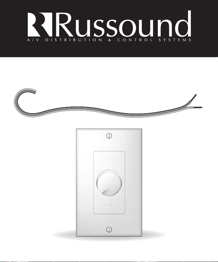
The LPTx UltraMatch™ Volume Control you have just purchased is a
wall-mounted Decora™ or Standard style, stereo speaker-level volume
control. It connects between the speaker outputs of an amplifier or
receiver and a pair of speakers.The X1 setting allows the volume control
to be used as a standard control. The X2, X4, and X8 settings allow it to
be used as an UltraMatch™ control. The UltraMatch™ volume control
provides a method of matching the minimum output impedance of the
amplifier or receiver, in addition to adjusting volume. It eliminates the
need for a speaker selector or impedance matching equipment. The
LPTx adjusts volume level by attenuating the amplifier signal output of
the LPTx to the speakers. All Russound Volume Controls are manufactured using a high-quality autoformer design which provides long life,
excellent frequency response, no heat build-up, and maximum power
transfer from the amplifier to the speakers.
INSTALLATION CONSIDERATIONS
• Near other wall controls
• Near a desk/workstation
• In entryways or exits
• At your bedside
• Close to a telephone and an intercom
• Near a jacuzzi
P-RING AND ELECTRICAL BOXES
From the wallplate/faceplate to the back of the LPTx control, the mounting depth of the LPTx. You must use a minimum of a standard light
switch plaster ring (p-ring) or a standard electrical box. Suitable P-Rings
and electrical boxes are available from your Russound dealer or a local
electrical supply company. Using the P-Ring during new construction
(some building codes require that wall devices be enclosed in electrical
boxes. Check your local building code) is best because it gives you
unobstructed access to the full depth of the wall.
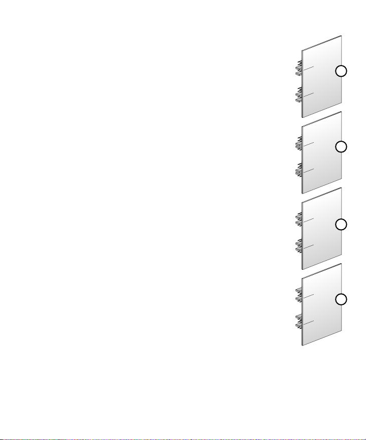
Jumper
Settings On
Circuit Boards
X1
X2
X4
X8
TYPE OF SPEAKER WIRE
For most applications, we recommend you use 16 or 18 gauge, stranded copper speaker
wire for the LPTx speaker connections. For wiring runs longer than 100 feet, 14 gauge
wire is recommended. Using speaker wire larger than 14 gauge for LPTx Volume Controls
is not recommended as the wire may not fit into the connectors. NOTE - Never use solidcore, aluminum or Romex® type wire with volume controls. When running speaker wires
inside walls, most states and municipalities in the U.S. specify that you must use a special
type of speaker wire. Usually, the requirement is that the wire has a specific “CL” fire rat-
2
Page 3

ing, such as “CL-2” or “CL-3”. Consult your Russound dealer, building contractor, or local
building and inspection department if unsure about which type of wire is best for your
application. If you need speaker wire, we recommend you order Russound AW series
wire. These speaker cables use multi-strand copper wire and high-temperature PVC jackets specially designed for snaking through the walls and for long speaker runs.
CAUTION
Do not install the LPTx into electrical boxes with 110 Volt devices. Some states or municipalities allow devices such as the LPTx to be installed into the same electrical box as 110
volt devices, provided a “low-voltage partition” is used between the devices. Russound
does not recommend this. Speaker wires can act as an “antenna” for electrical noise.
Locating speaker wires too close to a light switch or dimmer switch may cause a “humming” or “buzzing” sound to be heard through the speakers. If you must locate the volume control near electrical devices, install it in a separate metal electrical box, ground the
box to the electrical system ground, and route the speaker wires several feet away from
the electrical wiring.
OPERATION
1. Make sure the amplifier or receiver is OFF and set the volume to minimum.
2. Set the LPTx volume to maximum (fully clockwise).
3. Turn on the amplifier or receiver and select a music source, such as tuner or CD player.
4. Slowly turn up the amplifier or receiver volume and set it to a comfortable (not maximum) listening level. Be careful not to overdrive your amplifier. If the sound becomes
muddy or distorted, you have reached the limit of your amplifier’s volume capability
and should quickly reduce the volume to avoid damaging your speakers.
NOTE: 12 o’clock (50%) on most receivers is full volume. An amplifier that is being
driven beyond its potential will produce D/C voltage (clipping) resulting in improper signal transfer and possible amplifier shutdown or damage.
5. Adjust the volume of the speakers to the desired listening level using the LPTx.
6. You can turn off the speakers in each room by turning the knob on the LPTx completely
counter-clockwise.
IMPORTANT: If you are unsure of any of the installation procedures, the products
should be installed by a professional custom installer.
SPEAKER SELECTORS
If you are using a Russound speaker selector, locate the ON/OFF button which corresponds to the speaker pair you wish to play. Set it to the ON position.
3
Page 4

8X
4X
1X-2X
2X-4X-8X
1X
8X
4X
1X-2X
2X-4X-8X
1X
ULTRAMATCH™ VOLUME CONTROLS
Russound UltraMatch™ volume controls eliminate
the need for a speaker selector. By determining the
drive capability of the amplifier with a few simple
calculations, we can determine the number of
speakers the system can safely operate.
Fig 1
DETERMINING THE PROPER JUMPER SETTING FOR IMPEDANCE MATCHING
The jumper must be set in a position that correctly multiplies the impedance of the system
to a level that is equal to or greater than the impedance of the amplifier. The jumper setting can be determined using the following simple steps
1. Determine the amplifier's minimum impedance. The amplifier's minimum impedance
is usually found following Wattage and Frequency Response in the amplifier's specification page of the manual. It may also be listed on the back panel of the amplifier near
the speaker terminals. AC impedance is measured in ohms.
2. Identify the correct impedance-matching chart according to the amplifier's minimum
impedance. There are two impedance matching charts, one for 8 ohm amplifiers and
one for 4 ohm amplifiers. Choose the chart that describes your amplifier. If your amplifier is 6 ohm stable, use the 8 ohm chart.
3. Determine the impedance for each pair of speakers by referring to its manual.
4. Determine the total number of 4 ohm pairs of speakers. (rows on charts)
4
Page 5

5. Determine the total number of 8 ohm pairs of speakers. (columns on charts)
6. Follow the appropriate row and column to determine jumper settings. (ex. see fig 2)
Fig 2 Impedance Matching Charts For UltraMatch™
Impedance Matching For 4 Ohm Amplifiers
8 Ohm Pairs
012345678910111213141516
0-1X1X 2X 2X 4X 4X 4X 4X 8X 8X 8X 8X 8X 8X 8X 8X
11X2X2X4X4X4X4X8X8X8X8X8X8X8X8X
22X4X4X4X4X8X8X8X8X8X8X8X8X
34X4X4X8X8X8X8X8X8X8X8X
44X8X8X8X8X8X8X8X8X
58X8X8X8X8X8X8X
4 Ohm Pairs
68X8X8X8X8X
78X8X8X
8 8X
Impedance Matching For 8 Ohm Amplifiers
8 Ohm Pairs
Example: The table to the right shows
an 8 ohm minimum impedance
amplifier with 1 pair of 4 ohm speakers and 3 pair of 8 ohm speakers. The
chart indicates the jumper setting
should be set at 8X
012345678
0-1X2X 4X 4X 8X 8X 8X 8X
12X4X4X8X 8X 8X 8X
24X8X8X8X8X
38X8X8X
4 Ohm Pairs
48X
CONSIDERATIONS
1. Make sure that your amplifier has adequate wattage for the number of speakers. Watts
per channel divided by the number of pairs should equal or exceed the individual
speaker’s minimum wattage requirements.
2. You must use an UltraMatch™ volume control for each pair of speakers.
3. Every jumper setting must be set on the same setting throughout the system.
4. A minimum speaker load of 4 ohms can be connected to the output of each
UltraMatch™ volume control.
EZB CONNECTING BLOCKS
The EZB-1 and EZB-2 connecting blocks are Russound accessories that simplify connections
of multiple volume controls and speaker pairs. The EZB-1 is a neat, compact wiring device
capable of connecting four volume controls to an amplifier's outputs. The EZB-2 expands the
EZB-1 to another 4 volume controls. Multiple EZB-2's can be used to expand the system to
sixteen volume controls.
5
Page 6

WIRING INSTRUCTIONS
1. Connect the leads from the amplifier’s
outputs to the connector labeled input.
The wires should stay consistent, left +
of the amplifier to left + input of the volume control, observing polarity and
identification.
CAUTION: Do not reverse the input and
output connections!!
CAUTION: A majority of receivers are
designed to operate at a rating of 8Ω.
On receivers that offer A and B speaker
outputs, both A and B connections share
the same amplifier. It is important to
note, due to the way many receivers are
wired, that when using impedance
matching devices, such as UltraMatch™
volume controls, it is recommended to
wire all speakers to the A output. If you
have any questions contact Russound
directly.
2. As outlined in step #1, connect the
speaker wires to the connector labeled
output.
3. Install the completed assembly in the
junction box. Insert carefully to avoid
excessive strain on the connector. Taking
the time to feed the excess wire out the
back of the junction box will help you
with the final assembly.
AMP / Receiver
TO OTHER
VOLUME CONTROLS
INPUT
SPEAKERS SPEAKERS
SPEAKERS
TO OTHER
VOLUME
CONTROLS
L+ L- R- R+ L+
SPEAKERS
OUTPUTINPUT
L- R- R+
Speaker
Pair
6
Page 7

WARRANTY
All Russound volume controls are fully guaranteed against all defects in materials and
workmanship as long as the original purchaser and user of the volume control owns the
unit. During the warranty period, Russound, at its option, will replace or repair any defective part and correct any defect in workmanship without charge for parts or labor. For this
warranty to apply, the unit must be installed and used in accordance to its written instructions. If necessary, repairs must be performed by Russound. The unit must be returned to
Russound at the owner's expense and with prior written permission of Russound.
Accidental damage and shipping damage are not considered defects, nor is damage
resulting from abuse, or from servicing performed by an agent or person not specifically
authorized in writing by Russound. Damage to or destruction of components due to application of excessive power voids the warranty on those parts. Repairs to components damaged or destroyed due to application of excessive power will be made by charging the
owner the retail value of the parts and labor for the repair. To return items for repairs, the
unit must be shipped to Russound at the owner's expense, along with a written explanation of the nature of the service required. The unit must be packed in a corrugated container with at least 3 inches of resilient material to protect the unit from damage in transit.
Russound reserves the right to request proof of purchase. Except to the extent prohibited
by applicable law, no other warranties, whether expressed or implied, other than the
express warranties stated herein, shall apply to units sold to the purchaser. Russound shall
not be liable for any implied warranty of merchantability or fitness for a particular purpose
to any person other than the original purchaser and user. Under no circumstances shall
Russound be liable for property damage, economic loss or any consequential damages
sustained in connection with the purchase and use of its products. Some states do not
allow limitations on how long an implied warranty lasts, or do not allow the exclusion or
limitation of incidental or consequential damages, so the above limitations or exclusions
may not apply to you. Russound neither assumes nor authorizes any representative or
other person to assume for it any obligation or liability other than such as is expressly set
forth herein. This warranty gives you specific legal rights, and you may also have other
rights which vary from state to state.
7
Page 8

5 Forbes Rd. Newmarket, NH 03857
☎ 603.659.5170 • Fax 603.659.5388
e-mail: tech@russound.com
Come visit us at:
 Loading...