

Page 1
LCR7
Complement® On-Wall LCR Loudspeaker
Instruction Manual
Page 2
INTRODUCTION
Product Description
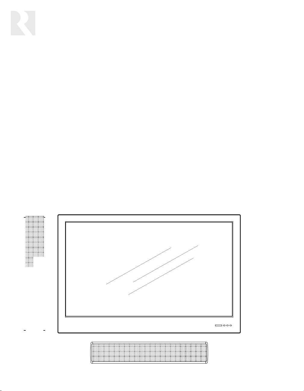
The Complement® LCR7 Loudspeaker is a wall-mounted
unit for home theater and stereo audio applications. Its
slender profi le is designed to complement the appearance of most fl at-panel video displays. The speaker
comes with two different-colored grilles to coordinate
easily with the room décor or other equipment.
In a home theater, the LCR7 is intended for use in the
front left, center, and right positions adjacent to the
video display. In stereo audio applications, a pair of LCR7
speakers can be used for the left and right channels.
Patent-pending Super Bessel Array™ technology in the
LCR7’s design improves sound dispersion. A special circuit in the speaker alters the response of certain drivers
at certain frequencies. This improves directivity at higher
frequencies, thus helping to broaden the listening area
when the speaker is mounted horizontally for use in the
center position.
The benefi t is that one speaker model can be used for
the three front channels in a home theater. This provides
identical voicing in all three positions, which improves
clarity and imaging.
Because the LCR7 is magnetically shielded, it can be
used next to CRT televisions without causing picture
distortion.
The LCR7 features an array of six mid/low-frequency
drivers coupled with a single high-frequency driver
to reproduce most of the audio spectrum. Its nominal
impedance is 6 ohms. A separate subwoofer is recommended to reproduce the lowest frequencies.
Surround speakers
Although intended primarily for use as front speakers,
the LCR7 can also be used as surround speakers in a
multichannel audio system. As an alternative, any Russound in-wall or in-ceiling speaker would work well for
the surround channels.
Subwoofer
Russound’s Complement Series subwoofers are ideal for
use with the LCR7 to extend the bass response of the
system. We recommend setting the subwoofer’s crossover frequency at 100 Hz.
2
Page 3
INSTALLATION
Speaker Placement
With either multichannel or stereo audio, careful speaker placement is important for proper imaging. Imaging is
the ability of the speaker system to reproduce sounds so
they appear to come from between the speakers.
Following are some general placement guidelines for
home theater applications. Other factors to consider for
speaker placement include:
• Suitable wall surfaces for mounting the speakers
• Proximity to room corners
• Locations where speaker cables can be run, either
hidden in the wall or attached to its surface
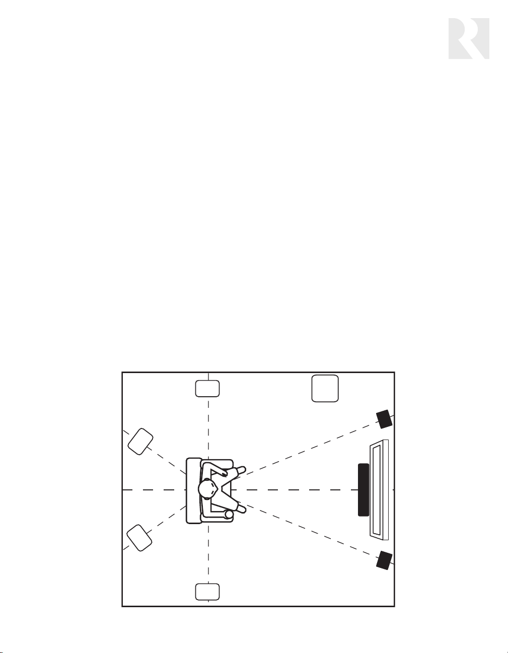
Home theater
In a multichannel audio system for a home theater, one
LCR7 should be installed horizontally above or below the
video display for the center channel, and two should be
installed vertically to the left and right of the display for
the main front channels.
The center-channel speaker should be as close to ear
level as possible; thus, if the video display is mounted
high, the speaker should be below it. If the display is
low, the speaker should be above it. The speaker should
then be angled up or down as needed so that its axis
points toward the ear level of the listeners.
The left and right speakers can be installed next to the
display or farther apart as desired. They should be angled
inward so their axes point toward the center listener.
For best results, we recommend placing the left and
right speakers so their centers are level with the listeners’ ear height. However, if the video display is centered
above or below ear height, it may be preferable to install
the left and right speakers level with the display for
aesthetic reasons.
Placement near corners
Placing a speaker near a corner of a room can cause
sonic refl ections off the side wall. This can result in a
loss of clarity and poor imaging. Accordingly, we do not
recommend placing the LCR7 near a corner unless the
side wall is covered with sound-absorptive material.
Generally, the best acoustic performance will result if
the left and right speakers are placed in similar positions
on the same type of wall surface.
Surround
Back Left
Surround
Back Right
Surround
Left
Subwoofer
Front Center
Surround
Right
Speaker placement for a home theater
LCR7
LCR7
LCR7
Front
Left
Front
Right
3
Page 4

INSTALLATION
Prewiring
Run a separate two-conductor stranded copper speaker
cable of at least 16 AWG (1.5 mm) from the amplifi er or
receiver to each speaker. Leave ample cable at the head
end to reach the amplifi er terminals. Label the cables so
you will know which cable connects to each channel.
We recommend running the cables through the walls to
the speaker locations whenever possible so as to hide
them. Be sure to use cable with the appropriate fi re
resistance rating for the application. Check the local
building code for specifi c requirements. Russound offers
a two-conductor speaker cable with a Class 3 fi re rating
for in-wall installation.
When running a speaker cable parallel to an AC power
cable, keep them at least 12 inches (30 cm) apart to
minimize electromagnetic interference. If the speaker
cables must cross AC wiring, cross them at right angles.
At each speaker location, bring the speaker cable out of
the wall in the center of the mounting bracket, leaving
about 2 feet (0.6 m) for connecting to the speaker.
Installing the Mounting Bracket
Note: The mounting bracket must be securely attached
to the wall. For a standard hollow wall, we recommend
screwing the bracket to the wall studs if possible. If the
speaker must be mounted between studs, use at least
three expandable hollow-wall anchors to secure the
bracket. For a masonry wall, use suitable anchors.
Installation on a hollow wall
1. Once you have determined roughly where the speakers will be mounted, use a stud fi nder to locate the
wall studs and mark their location.
2. Position the provided template where you want each
speaker, making sure to leave enough clearance for
rotating the speaker in the mounting bracket. Mark
the mounting screw locations.
Installation on masonry
1. Obtain masonry anchors suitable for the wall material.
2. Position the provided template where you want each
speaker, making sure to leave enough clearance for
rotating the speaker in the mounting bracket. Mark
the mounting screw locations.
3. With a masonry drill, make pilot holes for the anchors.
4. Attach the bracket to the wall with the anchors.
Connecting the Speaker
Connect the speaker cable before attaching the speaker
to the mounting bracket.
1. Strip 3 to 4 inches (7.6 to 10 cm) off the end of the
cable jacket. Then strip ½ inch (1.3 cm) of insulation
off the two wires.
2. Make sure the wire strands are twisted together so
there are no strands separated from the bundle.
3. Connect the wires to the speaker terminals, being sure
to observe proper polarity. For standard speaker cable
with red and black wires, connect the red wire to the
red positive (+) terminal and the black wire to the
black negative (–) terminal.
Note: Some speaker cables may have other ways of
designating polarity. For example, cable with a clear
jacket usually has a copper-colored wire for positive and
a silver-colored wire for negative. In a cable with white
and black wires, the white is positive and the black is
negative. Cable with both wires the same color may have
grooves, ribs, or stripes on the positive wire.
4. Check to make sure there are no stray strands of wire
outside the terminals. If there are, remove the wire,
twist the strands together, and reconnect the wire to
the terminal.
3. If you are attaching the bracket to studs, use a small
drill to make pilot holes for the mounting screws. If
you are using hollow-wall anchors, use a drill of the
size recommended by the anchor manufacturer.
4. Screw the mounting bracket to the wall studs with
appropriate screws, or secure the wall anchors in the
wall and attach the bracket to them.
4
Speaker cable connection
Page 5

INSTALLATION
Attaching the Speaker
1. Place the disc spring washers over the socket head
screws with the convex sides against the screw heads.
2. Thread the socket head screws into the mounting
bracket. Leave at least ¼ inch (6 mm) of space
between the washers and the bracket ends.
3. Align the slots on the ends of the speaker with the
screws and slide the speaker fully onto the bracket,
pushing any excess cable back into the wall. Make
sure the washers are between the screw heads and the
speaker ends. Finger tighten the screws.
4. Aim the speaker according to the guidelines given in
the previous section on speaker placement.
5. Tighten the screws with the hex key provided.
6. Press the end caps into place.
Changing the Grille
The LCR7 comes with two different grilles, one of which
is attached to the speaker. To remove the grille:
1. Starting in one corner, insert the grille removal tool
into the edge of the grille and gently pull it slightly
away from the speaker. Continue along the short dimension and then around the entire edge of the grille.
Do not pull the grille completely off the speaker until
the edge is loosened all the way around.
2. When the entire edge is loosened, grasp the grille by
the edges and gently pull it off the speaker evenly.
Avoid bending the grille.
To attach the grille:
1. Align the edge of the grille with the recess in the
speaker cabinet.
2. Gently push the grille in place evenly around the
edge. Do not push on the center of the grille.
Rotating the Logo Badge
The logo badge is permanently attached to the grille,
but can be rotated to accommodate both vertical and
horizontal speaker orientations. To rotate the badge,
simply pull it straight away from the grille and turn it.
5
Page 6

INSTALLATION
Connecting the Amplifi er or Receiver
The LCR7 is designed to be driven by an amplifi er or
receiver with a rated output of up to 150 watts RMS per
channel into 6 ohms.
1. Make sure the amplifi er or receiver is turned off.
2. Strip 1 to 2 inches (2.5 to 5 cm) off the end of each
cable’s jacket. Then strip just enough insulation
off each wire to make a secure connection to the
amplifi er’s speaker terminals.
3. Make sure the wire strands are twisted together so
there are no strands separated from the bundle.
4. Connect the wires to the speaker terminals, being
sure to observe proper polarity. (If preferred, attach
suitable connectors such as banana plugs to the wires
before connecting them.)
5. Check to make sure there are no stray strands of wire
outside the terminals. If there are, remove the wire,
twist the strands together, and reconnect the wire to
the terminal.
Confi guring Your Receiver
Your home theater receiver or surround processor
most likely has a choice of settings for different types
of speakers. If your receiver or processor has an auto
setup procedure, you will probably get the best results
using the auto setup. If you use a manual speaker setup
procedure, you will get the best results by setting the
LCR7 speakers to the Small setting if you are using a
subwoofer, or the Large setting if you are not using a
subwoofer.
Saving your speakers from signal clipping
When a source audio signal demands more power than
the amplifi er can produce, signal clipping can result.
This means the negative and positive peaks of the
amplifi er’s output signal are clipped off. This can occur
if the input signal level is too high.
Clipping generates a direct-current (DC) component
in the output signal. It also generates unwanted lowfrequency or subsonic artifacts. This energy is capable
of causing speaker distortion or driver damage.
Signal clipping may or may not be audible. When it is,
it can be heard as distortion. Whether you can hear
it or not, clipping can damage audio components,
especially speakers.
Clipping can happen with a receiver when its volume
control is turned up too high (above 40 to 50 percent),
especially when the receiver is driving more than one
speaker per channel. It can also happen when the
amplifi er doesn’t have enough power for the speaker
load. Amplifi ers with high-current designs are less
likely to clip because they’re capable of producing
more current during peaks in the audio signal.
To prevent amplifi er clipping, choose an appropriate
amplifi er for the speaker load. Use a dedicated AV receiver or multichannel amplifi er for driving the home
theater speakers and a separate multiroom controller
or amplifi er to drive the whole-house music system.
Make sure the amplifi er is rated to handle the impedance of the speakers. For example, 8-ohm speakers
can be driven by amplifi ers rated at 4 or 8 ohms, but
4-ohm speakers require an amplifi er with a 4-ohm
output rating.
Taking Care of Your Speakers
Your LCR7 speakers are made of durable materials that
need very little care. All we recommend is an occasional
dusting with a soft cloth or light vacuuming with a dust
brush attachment. If you vacuum the speakers, leave the
grilles in place to avoid damaging the drivers.
Do not use any harsh detergents, chemical solvents, or
abrasive materials on your speakers.
6
For home theater applications, we recommend at least
30 watts of amplifi er power per LCR7 speaker. We also
recommend using an amplifi er with a high-current
design. Keep in mind that it’s generally safer to have
more power available than not enough.
Page 7

Specifi cations
Loudspeaker type: Passive 2-way line array, single input, magnetically shielded
Mid/low-frequency drivers: (6) 3.5” (8.9 cm) polypropylene cones
High-frequency driver: 1” (2.5 cm) silk dome, wide surround
Frequency response: 104 Hz – 20 kHz ±3 dB
Frequency range: 88 Hz – 20 kHz +3/–6 dB
Nominal impedance: 6 ohms
Sensitivity: 85 dB SPL, 2.83 V at 1 meter
Recommended amplifi er power: 30–150 watts RMS (CEA-426-B specifi cation)
Terminals: Color-coded binding posts
Overall dimensions: 4.5” W x 25.25” H x 4.875” D (11.4 x 64.1 x 12.4 cm)
(cabinet and mounting bracket, vertical orientation)
Mounting bracket dimensions: 2.38“ W x 24.14“ H x 1.5“ D (6.0 x 61.3 x 3.8 cm)
Weight: 17.5 lb (7.94 kg)
Finish: Black or silver cabinet with black and silver grilles
Super Bessel Array™ is a Patent Pending technology.
REFERENCE
Warranty
Russound LCR7 Loudspeakers have a Limited Lifetime Warranty against defects in materials and workmanship. During the warranty
period, Russound will replace any defective part and correct any defect in workmanship without charge for either parts or labor.
Russound may replace returned speakers with a product of equal value and performance. In such cases, some modifi cations to the
mounting may be necessary and are not Russound’s responsibility.
For this warranty to apply, the speaker must be installed and used according to its written instructions. If repairs are necessary, they
must be performed by Russound. The speaker must be returned to Russound at the owner’s expense and with prior written permission.
Proof of purchase must accompany all claims. Accidental damage and shipping damage are not considered defects, nor is damage
resulting from abuse or from servicing performed by an agency or person not specifi cally authorized in writing by Russound.
This warranty does not cover:
• Damage caused by abuse, accident, misuse, negligence, or improper operation or installation.
• Products that have been altered or modifi ed.
• Any product whose identifying number or serial number has been altered, defaced, or removed.
• Normal wear and maintenance.
Damage to or destruction of components due to application of excessive power voids the warranty on those parts. In these cases,
repairs will be made on the basis of the retail value of the parts and labor. To return for repairs, the speaker must be shipped to Russound at the owner’s expense, along with a note explaining the nature of service required. Be sure to pack the speaker in a corrugated
container with at least 3 inches of resilient material to protect the speaker from damage in transit.
Before returning a speaker for repair, call Russound at 603.659.5170 for a Return Authorization number. Write the RA number on the
shipping label and ship to: Russound, ATTN: Service, 5 Forbes Road, Newmarket NH 03857.
Russound sells products only through authorized Dealers and Distributors to ensure that customers obtain proper support and service.
Any Russound product purchased from an unauthorized dealer or source, including retailers, mail order sellers and online sellers will
not be honored or serviced under existing Russound warranty policy. Any sale of products by an unauthorized source or other manner
not authorized by Russound shall void the warranty on the applicable product.
7
Page 8

LCR7
Complement® On-Wall LCR Loudspeaker
Instruction Manual
Russound
5 Forbes Road, Newmarket NH 03857 USA
Tel 603.659.5170 • Fax 603.659.5388
www.russound.com
Technical Support: tech@russound.com 28-0044 Revision 2 11/19/07
Copyright © 2007 Russound. All rights reserved. All trademarks are the property of their respective owners. Specifi cations are subject to
change without notice. Russound is not responsible for typographical errors or omissions.
 Loading...