

Page 1
IRB-6
1
EMITTERS
POWER
STATUS
2
3
4
Instruction Manual
Page 2
Product Overview
The IRB-6 provides an effective in-wall method to connect
Infrared components. The IRB-6 can conenct up to 12 infrared
receivers and allows control of up to 8 infrared controlled
devices.
IMPORTANT – Read the manuals that are included with the IR
receivers and other IR equipment you intend to install with the
IRB-6. It is important that you are familiar with the connection
and operation of these devices. If you are unsure of any of the
following installation procedures, this product should be
installed by a professional custom installer.
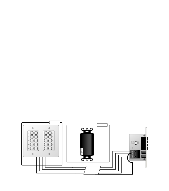
IR Receiver / Keypad Connections
1) Run 22 gauge, 4 conductor, shielded cable with drain wire,
such as Russound Pt. No. AW2260AB, from each of the IR
receivers or keypads into a standard electrical junction box
as shown in Figure 1.
ROOM A
RECEIVER
ROOM B
Figure 1
848
J-BOX
IRB-6
+12V
OUT
OUT
GND
+12V
STATUS
GND
22 AWG
4 Conductor
Sheilded
Cable w/ Drain
+V
GND
ST
SIG
drain wire
connected
to GND
terminal
CONFIRM
2
Page 3

2) Make sure that the power adapter is not connected to the
IRB-6.
3) Connect the wires to each of the installed IR receivers or
keypads as shown in Figure 1.
4) Connect the other end of all IR receivers or keypad wires to
the +V, GND, SIGNAL (SIG) and STATUS (ST) terminals of
the IRB-6 as shown in Figure 1. A maximum of 12 IR
receivers or 4 learning keypads can be connected to the IRB6 when only one Model #846C Power Supply is used. More
IR devices can be connected by using a higher-current, regulated power supply. IR receivers usually consume approximately 10mA – 15mA each, while most learning keypads
consume approximately 50mA each.
NOTE – The STATUS connection is for use with IR receivers
or keypads that have Status feedback capability (see your IR
receiver or keypad documentation).
5) Make sure that the drain wire of the cable is connected to
the GND terminal of the main input connector on the back
of the IRB-6. The drain wire does not need to be connected
to the ground connection of the IR receiver or keypad.
3
Page 4

IR Emitter Connections
1) Connect the 1/8" plug of either the Model #845 or #1584
emitter to one of the emitter outputs at the front of the IRB-6
as shown in Figure 2. Up to 4 emitters can be connected to
the IRB-6. When using the Model #1584 emitters, up to 8 IR
controlled devices can be controlled.
2) Following the instructions that came with your IR emitter,
place the other end of the IR emitter onto the IR sensor window of the equipment to be controlled.
Power Supply and Status Input Connections
1) Connect the Model #846C Power Supply to the POWER
connection at the front of the IRB-6 as shown in Figure 2.
2) Check all connections and then plug the power supply into
an unswitched AC receptacle.
3) Check for proper operation of all IR receivers or keypads.
The CONFIRM indicator located on the circuit board of the
IRB-6 gives a visual indication that the signals from the IR
receivers or keypads are being successfully transferred to the
IRB-6.
4) If the installed IR receivers or keypads have Status feedback
capability, another Model #846C Power Supply can be connected to the STATUS input at the front of the IRB-6 as
shown in Figure 2.
4
Page 5

Figure 2 – The power supply would be plugged into a switched
1
EMITTERS
POWER
STATUS
2
3
4
Model 846C
Power Supply To Unswitched
AC Outlet
To Switched
AC Outlet
of A/V Receiver
Model 846C
Power Supply
SATELLITE RECIEVER
CD PLAYER
TUNER
DVD PLAYER
AC receptacle, usually on the back of the audio receiver being
used. Please read the IR receiver or keypad documentation for
the details of this feature.
Figure 2
Installation
1) Check all connections, and proper system operation before
installing the IRB-6 into the wall.
2) Using the included hardware, install the IRB-6 into a standard electrical box.
5
Page 6

Limited Warranty
The Russound IRB-6 is fully guaranteed for Two (2) years from the date of
purchase against all defects in materials and workmanship. During this
period Russound will replace any defective parts and correct any defect in
workmanship without charge for either parts or labor. For this warranty to
apply, the unit must be installed and used according to its written instructions. If service is necessary, it must be performed by Russound. The unit
must be returned to Russound at the owner’s expense and with prior writ-
ten permission. Accidental damage and shipping damage are not considered defects under the terms of the warranty. Russound assumes no
responsibility for defects resulting from abuse or servicing performed by
an agency or person not specifically authorized in writing by Russound.
Damage to or destruction of components due to improper use voids the
warranty. In these cases the repair will be made at the owner’s expense. To
return for repairs, the unit must be shipped to Russound at the owner’s
expense, along with a note explaining the nature of the service required.
Be sure to pack in a corrugated container with at least 3 inches of resilient
material to protect the unit from damage in transit.
5 Forbes Rd. Newmarket, NH 03857, USA
☎ 603.659.5170 • Fax 603.659.5388
e-mail: tech@russound.com
Come visit us at:
6
 Loading...