

Page 1
Flexbox Back Box Installation
Introduction
Russound's speaker back box oers an innovative acoustic barrier that
will reduce background noise, furnish a moisture barrier, diuse
distortion, and improve sound quality. It is easily installed in both new
construction and retrot settings. The design incorporates a exible
construction with noise-absorbing materials. Both models are ame
retardant and meet the following standards: ASTM E119 and UL 263/
NFPA 251 (1-hour) and ASTM E84/NFPA 70. The Flexbox back box is sized
to t between the studs with depths of 3.5" (89 mm) for the in-wall
enclosures and 6" (152 mm) for the in-ceiling models. As a retrot solution
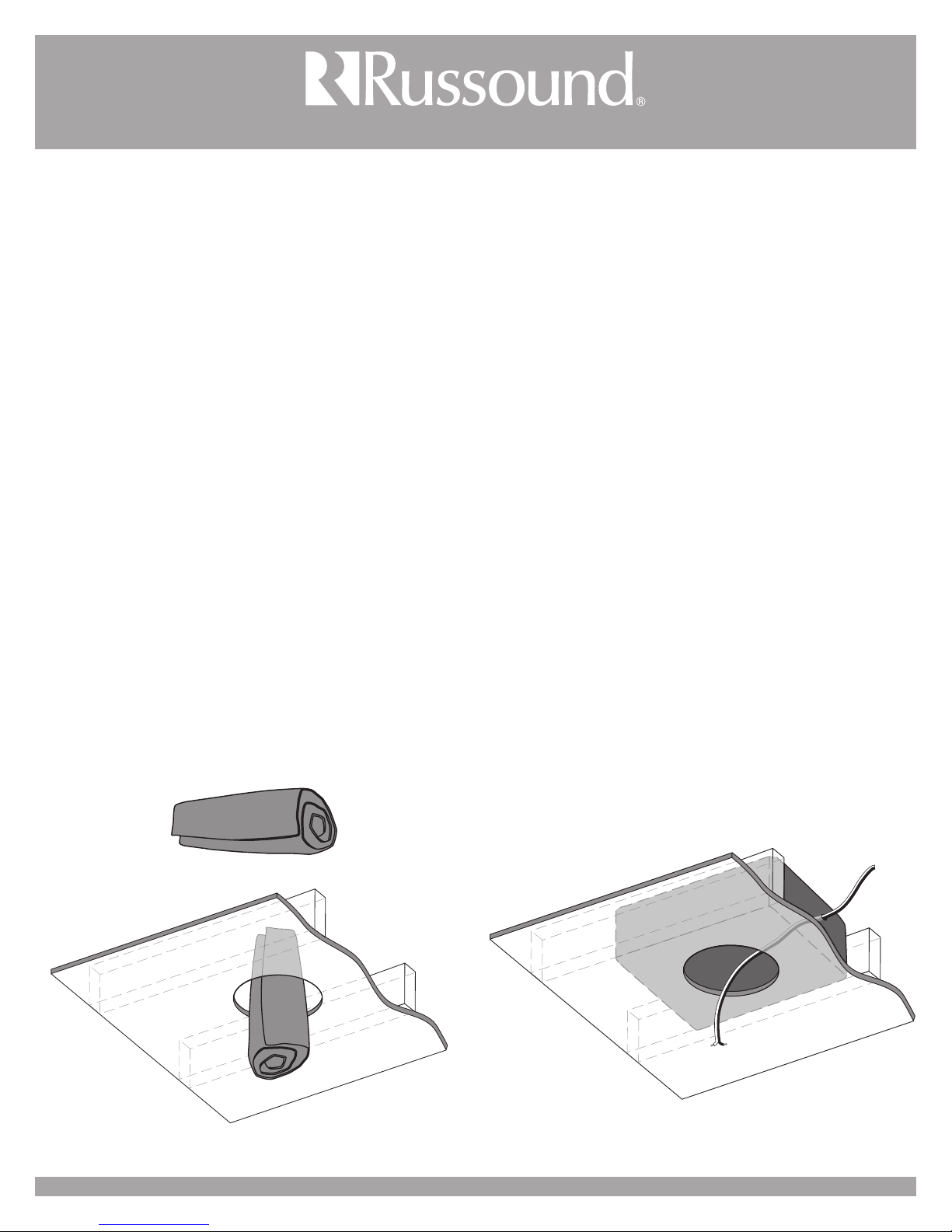
for in-ceiling speakers, it can be rolled up, inserted through the hole in
the drywall, and secured to the studs or drywall prior to installing or reinstalling the speaker.
Retrot Installation (In-ceiling only)
Poke a small hole or slit in one of the back box sidewalls for the 1.
speaker wire.
Consult with building plans to locate existing pipes, duct work, and 2.
AC wiring and to make sure location of speaker has proper depth and
space between studs.
Cut the hole in the wallboard or drywall as specied by the speaker 3.
manufacturer.
Pull the necessary wire to the nal speaker location and through the 4.
hole made in the sidewall of the back box.
Flatten and roll up the box and push through the hole. 5.
Center the box on the center of the cutout and trim excess material. 6.
(Optional) Apply caulking around the inside of the drywall opening 7.
and adhere the face of the box to the drywall. (**Apply re-rated
caulking if applicable - See Important note at right.)
Connect the speaker wire to the speaker and install the speaker 8.
according to the manufacturer’s specications.
Installation - New Construction (In-wall or In-ceiling)
Poke a small hole or slit in one of the back box sidewalls for the 1.
speaker wire.
Choose the stud opening that best suits the speaker application. 2.
The speaker location should be free of obstacles (electrical wiring,
plumbing, duct work). Refer to the speaker manual for the minimum
clearance depth for the speaker.
Place the back box between two studs with the front face ush with 3.
the front edge of the studs. Screw, nail or staple the box to the stud
from the inside of the back box.
Pull the speaker wire through the hole in the back box sidewall. 4.
Attach speaker brackets (if applicable) to the studs, centering the 5.
bracket on the back box cutout. Refer to the bracket installation
instructions. Trim any excess material from the opening of the back
box using a sharp knife and the bracket as a guide.
Provide the drywall installer with the precise location and dimensions 6.
of the speaker brackets. The speaker cutout (hole) must not extend
further than ¼" (0.6 cm) from inside of the mounting bracket.
After drywall is hung, trim any excess material if necessary. 7.
(Optional) Prior to speaker installation, apply caulking around the 8.
inside of the drywall opening and adhere the face of the box to the
drywall. (**Apply re-rated caulking if applicable - See Important note
below.)
Connect the speaker wire to the speaker and install the speaker 9.
according to the manufacturer’s specications.
**Important: For re rated installation, seal the hole where the speaker
wire comes into the back box with re rated caulk. (3M’s Fire Barrier Sealant
FD150+ or FD200+ is recommended). Coating around the edge of the
drywall side of the box is not required but could be added to create a strong
acoustic seal.
Flatten and Roll Back Box
Insert in Opening
Page 1 of 2
Secure to studs and drywall
Trim excess material around opening
Page 2

Page 2 of 2
Flexbox Back Box Information
Additional Tips / Considerations
If possible, run speaker wires after AC wiring is in place to avoid •
induced hum caused by close parallel proximity of the two types of
wire.
Avoid running speaker wires close to house electrical wiring for any •
distance. If you have to run them parallel, leave two feet between the
wiring. Speaker wires should cross AC lines at a 90° angle.
Technical Specications
Route horizontal wire runs through holes drilled in studs at roughly •
equal heights.
Secure speaker wires in place against a stud along vertical runs with •
insulated staples only. Do not pierce the wire insulation. Allow a bit of
slack for expansion of building materials.
FBC1-FR Flexbox Fire Rated In-ceiling Back Box
Dimensions: 14"W x 6"D x 17.5"H ( 355 x 152 x 445 mm)
Material Thickness: 1" (25 mm) nominal thickness
Weight: 6.7 lbs (3 kg)
Material: Proprietary Composite Material
STC Rating: 32
Flame Spread: 23
Smoke Density: 30 (ASTM E84/ NFPA 70)
Thermal Value: R 4.2
Temperature Range: -40° F to 350° F (-40°C to 177°C)
Fire Rating: CLASS 1 Fire Rated
ASTM E119 /NFPA 251 and UL 263
for 1 Hour Fire Rating
FBW1-FR Flexbox Fire Rated In-wall Back Box
Dimensions: 14.5"W x 3.5"D x 16"H ( 368 x 89 x 406 mm)
Material Thickness: 1" (25 mm) nominal thickness
Weight: 5.4 lb (2.4 kg)
Material: Proprietary Composite Material
STC Rating: 32
Flame Spread: 23
Smoke Density: 30 (ASTM E84/ NFPA 70)
Thermal Value: R 4.2
Temperature Range: -40° F to 350° F (-40°C to 177°C)
Fire Rating: CLASS 1 Fire Rated
ASTM E119 /NFPA 251 and UL 263
for 1 Hour Fire Rating
©2009 Russound. All rights reserved.
All trademarks are the property of their respective owners.
Specications are subject to change without notice.
Russound is not responsible for typographical errors or omissions.
Russound, Inc.
5 Forbes Road, Newmarket, NH 03857
tel603.659.5170•fax603.659.5388
email: tech@russound.com www.russound.com
28-1337 1/08/09
 Loading...