

Page 1
PROCEDURE FOR REPLACEMENT OF
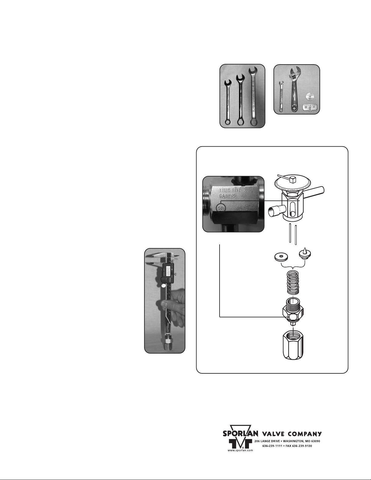
52 Date Code
Y1128 BIVE 3
GABP/5
52
KA-4 ADJUSTABLE BOTTOM CAP ASSEMBLIES
On Valves With Special Or Standard Superheat Settings
ools Required:
T
(1) – 15/16” Open End Wrench (fits valve body)
(1) – 7/8” Open End Wrench (fits bottom adjustment assembly)
(1) – 3/4” Open End W
(1) – Dial caliper, depth micrometer, steel rule, or other tool for measuring the depth.
(1) – Adjustment stem tool, 3/16” open end wrench, or small crescent wrench to
adjust bottom adjustment assembly. Must be a tool that allows the exact turns
of adjustment made on the bottom adjustment assembly to be counted.
Service Ratchet Not Recommended.
Installation Instructions:
Determine if the valve has a special OEM setting. Valves with special
OEM settings are indicated by a number stamped on the bottom
adjustment assembly or on the valve body, e.g. 52. See Figure 2.
If the valve does not have a special OEM setting (no number/setting
marked on valve) follow Steps 1 and 2, then skip to Step 3.
A special setting can be approximated using one of two possible
methods, as described below in
1. Before disassembling the TEV, be sure the refrigerant pressure in
the system has been reduced to a safe level (0 PSIG).
2. Disassemble the bottom adjustment assembly and seal cap from the
valve body.
ment assembly at this time. See Figure 2.
Method A
Use a dial caliper or other method for measuring the distance from the top of the bottom
adjustment assembly (see Figure 1) to the
spring guide surface inside the
adjustment assembly. Record this measurement
or mark this dimension on the tool used for
measuring the depth.
Remove seal cap from
bly. Adjust spring guide position to same position as measured above on
to Step 3.
rench (fits seal cap)
Method A and Method B.
DO NOT remove the seal cap from the bottom adjust-
OLD bottom
NEW bottom cap assem
-
OLD assembly. Skip
KA-4 for Valve Types BBI*, (E)BF, (E)BQ,
(E)F, (E)Q, FB, SBF, SBQ, SQ
Valve setting indicated on valve body
or bottom adjustment assembly.
SPRING GUIDE
(BBI, BQ, CBBI, (E)BF,
EBQ, RC, SBF, SBQ)
October 2004
Tool options for adjusting the stem
on bottom adjustment assembly.
VALVE BODY
PUSHRODS
PIN & CARRIER
(CBI, (E)F, EQ,
FB, Q, SQ)
SPRING
BOTTOM
ADJUSTMENT
ASSEMBLY
Method B
Remove the seal cap from the OLD bottom
adjustment assembly
stem out counterclockwise, counting the number of turns until you come in contact with the
stop on the adjustment stem. The adjustment
stem will turn freely until you come in contact
. Back the adjustment
Figure 1
Figure 2
SEAL CAP
* For straight through connections ONL
.
Y
with the stop.
Remove the seal cap from the
Make certain that the adjustment stem on the
NEW bottom adjustment assembly
NEW bottom adjustment
assembly is backed out counterclockwise all the way. Turn the adjustment stem on the
NEW bottom adjustment assembly clockwise the
same number of turns that you backed the adjustment stem out on the
OLD bottom adjustment assembly
.
.
4. Install seal cap on NEW bottom adjustment assembly and tighten
with wrenches 1/8 to 1/6 of a turn beyond hand tight. This cap is the
primary seal.
5. After system is started, check and verify proper superheat setting
as recommended by the Equipment Manufacturer
.
3. Install NEW replacement bottom adjustment assembly. It is impor-
tant
that the PIN remains seated in the valve port, otherwise flood
ing will occur. Tighten with wrenches approximately 1/4 of a turn
beyond hand tight.
PRINTED IN THE U.S. OF A. SD-24B-1004
-
© COPYRIGHT 20 04 BY SPORLAN VALVE COMPANY, WASHINGTON, MO
 Loading...