

Russell FT18-17 Installation Manual
INSTALLATION OPERATION
N
A
T
I
O
N
A
L
S
A
N
I
T
A
T
I
O
N
F
O
U
N
D
A
T
I
O
N
U
L
®
C
US
AND MAINTENANCE INSTRUCTIONS
Flex - Temp
IOM 121
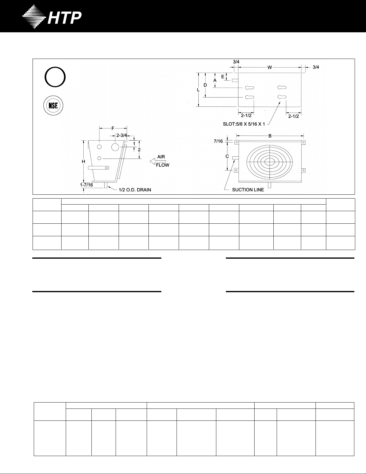
MODEL
NUMBER
FT 18-6
FT 18-8
FT 28-12
FT 18-17
FT 18-23
FT 18-31
H
6-3/4
6-3/4
7-3/4
9-5/8
11-5/8
11-5/8
L
8-15/16
8-15/16
8-15/16
10-9/16
13
13
W
12-1/2
12-1/2
18
14
16-3/4
16-3/4
DIMENSIONS (in)
A B
4-5/16
4-5/16
4-1/2
5-1/4
5-1/4
5-1/4
12-3/4
12-3/4
18-3/4
14-5/8
17-1/2
17-1/2
C
4-5/8
4-5/8
4-5/8
5-1/4
7
7
DEF
5-5/16
5-5/16
5-5/16
9
11-1/2
11-1/2
4-1/4
4-1/4
4-1/4
4-3/4
4-1/2
4-1/2
3-15/16
3-15/16
4-1/16
5-1/2
5-5/16
5-5/16
PPRX.
A
SHIP WT. (lbs)
9
9
14
15
20
23
GENERAL
RECEIPT AND EXAMINATION
Carefully check all items against bill of lading to be sure everything has been received as ordered. Carefully inspect all items for damage and, if any is
found, report it immediately to the carrier and file damage claim with same.
INSTALLATION
LOCATION AND MOUNTING
The FT is designed to mount on a wall or ceiling. The unit should be installed so that there are no restrictions on the air inlet or outlet as this will cause
the refrigeration system to operate less efficiently.
Remove the unit from the carton. Using the fastener holes in the unit as a guide, locate the mounting fasteners on the wall or ceiling in the reach-in
cooler. Use #10 screws or 1/4” diameter bolts to secure the unit to the wall or ceiling. This unit must be installed so as to allow drainage of condensate
coming off the coil.
The National Sanitation Foundation (NSF) requires that any flush mounted unit be properly and completely sealed, with an approved NSF
between the unit and the mounting surface.
ELECTRICAL
System electrical installation should conform to all applicable codes and practices.
according to the nameplate motor circuit electrical ratings.
All models will require the connection of power to the fan motor
sealant,
REPLACEMENT PARTS
To order replacement parts, contact your local representative or contact the factory (800) 288-9488 for the location of the nearest HTP wholesaler.
Always provide the evaporator model number
MOTOR
AN
HP
9 Watt
F
MOTOR
RPM
3000
3000
3000
1550
1550
1550
Model
Number
FT 18-6
FT 18-8
FT 28-12
FT 18-17
FT 18-23
FT 18-31
MOTOR
43 Watt
43 Watt
43 Watt
1/20 HP
1/20 HP
, serial number
PAR T
NUMBER
102249005
102249005
102249005
103104004
102540003
102540003
, unit voltage and a complete description of the part required.
FAN BLADE
BORE DESCRIPTION
1/4”
1/4”
1/4”
1/4”
5/16”
5/16”
621 CW
621 CW
621 CW
831 CCW
1025 CCW
1025 CCW
PAR T
NUMBER
105849001
105849001
105849001
204395010
214022000
214022000
FAN GUARD
DIA.
6”
6”
6”
8”
10”
10”
PAR T
NUMBER
205932000
205932000
205932000
206569000
201006002
201006002
DRAIN PAN
PAR T
NUMBER
20985600
20985600
20985500
20985400
20985300
20985300
Part No. #08499047
 Loading...