

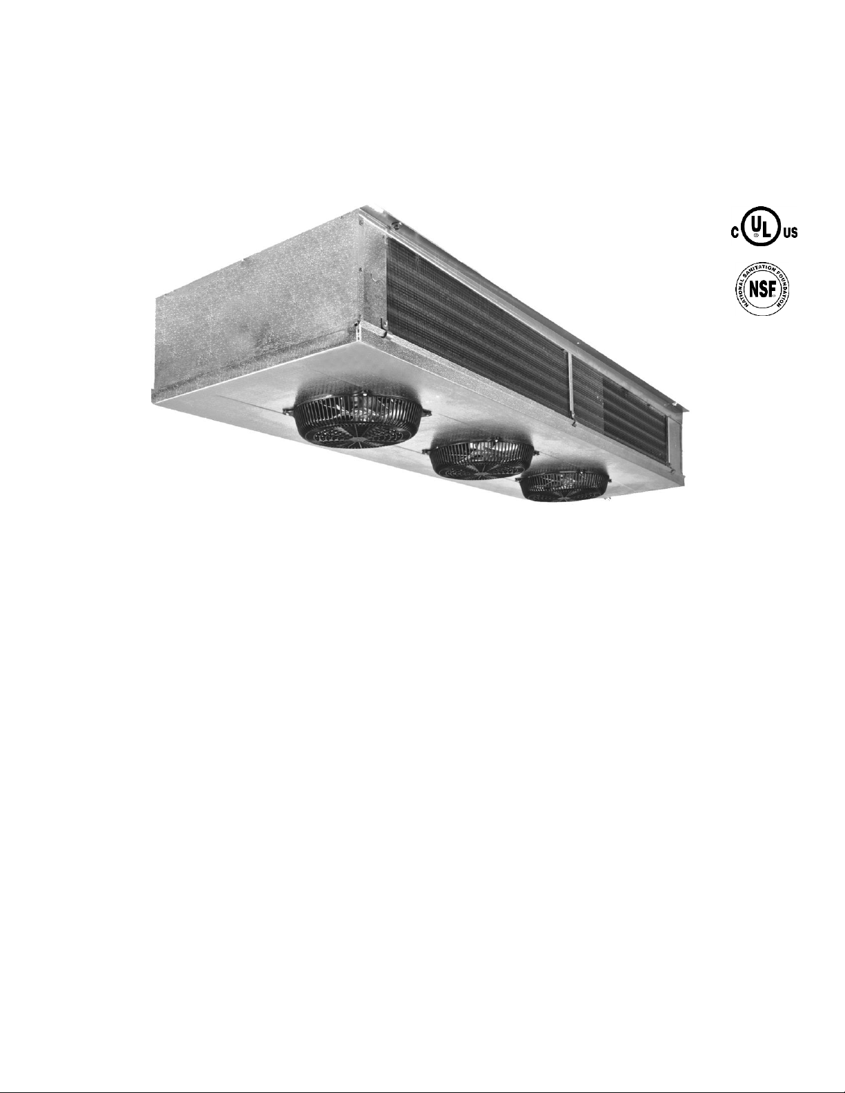
Russell FL26-67, WF-050 Installation Manual
Installation, Operation, and
Part # 08499173
Maintenance Information
Low Velocity Unit Coolers
Bulletin No. IOM 110.3
Table of Contents
Inspection ................................................................................................................................................................................ 2
Installation ....................................................................................................................................................................... 2 – 4
General .................................................................................................................................................................................... 2
Location ............................................................................................................................................................................... 2
Drain Line ............................................................................................................................................................................ 3
Refrigerant Piping ................................................................................................................................................................ 3
Expansion Valve .................................................................................................................................................................. 3
Evacuation ........................................................................................................................................................................... 3
Wiring ............................................................................................................................................................................. 3 - 4
Typical Wiring Diagrams ................................................................................................................................................. 4
Start-up Procedure .......................................................................................................................................................... 5 – 6
System Check ......................................................................................................................................................................... 5
Initial Start-up ...................................................................................................................................................................... 5
Superheat Adjustment ................................................................................................................................................... 5 – 6
Maintenance..................................................................................................................................................................... 6 – 7
General ................................................................................................................................................................................ 6
Cleaning ............................................................................................................................................................................... 6
Check-up .............................................................................................................................................................................. 6
Fan Blade and Motor Replacement ..................................................................................................................................... 6
Defrost Heater Replacement ............................................................................................................................................... 7
Troubleshooting Chart ......................................................................................................................................................... 7
Replacement Parts ................................................................................................................................................................ 8
Service Record ...................................................................................................................................................................... 8
HTPG ● www.htpgusa.com
INSPECTION
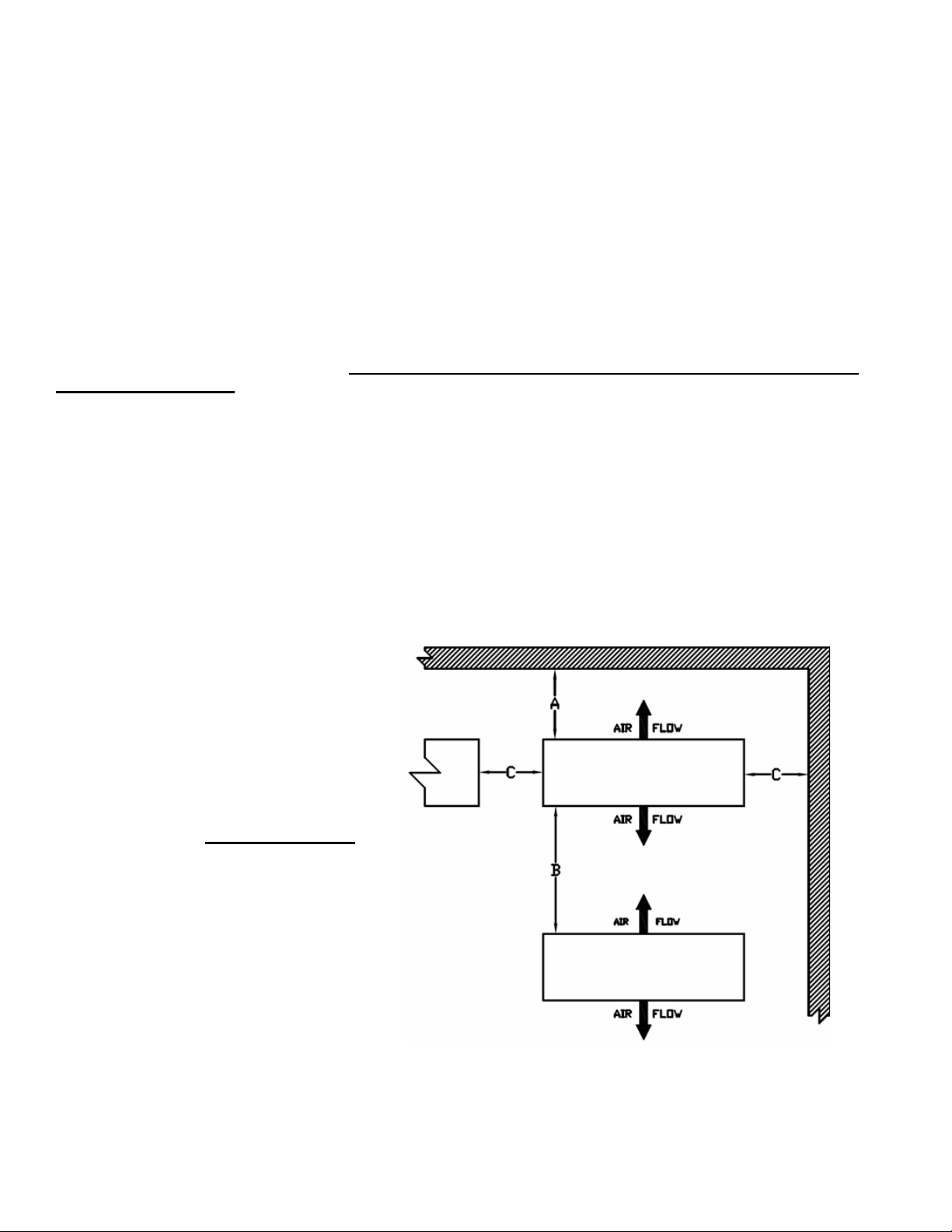
A B C
Min. 5 10 2
Max. 15 30 10
Dimension (Ft.)
Part # 08499173
When the equipment is received, the number of crates and cartons should be checked against the bill of lading. Any
damage or shortages should be noted immediately and a report given to the freight carrier and the manufacturer. It is the
customer’s responsibility to file all freight claims with the carrier. Verify that the voltage listed on the unit nameplate
matches the power supply available.
INSTALLATION
General
Installation and maintenance must be performed by qualified personnel who are familiar with the local codes and
regulations and who are experienced with this type of equipment. When mounting the units, lift and handle them by the
cabinet or hanger flanges only. Lifting by the tubing or fan guards may result in damage to the unit. The unit should be
mounted level to ensure proper drainage. Caution: Avoid contact with sharp edges and coil surface as they are
potential injury hazards.
Location
Determine the best location for the unit cooler in the room to be refrigerated. Placement of the unit should be centered in
the room and away from doors to keep warm, outside air from being drawn into the unit. This dual discharge unit draws air
up through the fan blades and discharges it through the coil surface. Figure 1 shows the proper clearances that should be
maintained for proper air flow and service access to the unit. Allow at least 36 inches space below the drain pan for air
flow and service access. Before unit is raised into position all packaging should be removed while taking care not to
damage the drain fitting or refrigerant connections. The unit should be supported on 5/16” minimum rod hangers, or 5/16”
minimum lag bolts, at all mounting slots. To meet NSF requirements, the unit must be positioned flush with the ceiling and
all gaps properly caulked. If hung below the ceiling, adequate space for cleaning must be provided per NSF requirements.
Drain Line
Figure 1: Unit Location (Top View)
2

The drain line should be pitched at a minimum of 1/2” per foot to allow proper drainage and should exit the refrigerated
Part # 08499173
space as soon as possible. The drain line should be insulated and sealed to protect from freezing where it passes
through the wall and a trap provided outside the refrigerated area. In rooms with temperatures below 34° F, the drain line
should be heated and insulated.
Refrigerant Piping
Refrigerant piping should be installed in accordance with all applicable codes and using good refrigeration practices. For
liquid and suction line sizing, refer to the ASHRAE Refrigeration Handbook. A trap must be installed prior to any risers in
the suction line. Horizontal suction lines should be sloped at a minimum of 1/8” per foot to provide proper oil return to the
compressor. Suction lines should be properly insulated to prevent sweating and higher return gas temperatures.
Expansion Valve
Expansion valves are to be sized and installed in accordance with the valve manufacturer’s recommendations. Valves
should include an external equalizer line, which must be connected. Proper location of the sensing bulb is extremely
important to the performance of the coil. Good thermal contact to the suction line is essential. On solder type valves, a
wet cloth wrapped around the valve during installation will help protect it from overheating and damage during the
installation process.
Evacuation
Proper evacuation is essential prior to charging the system. This avoids many problems that may arise due to lack of
detail in this step. After charging, the system should be checked through all cycles to ensure proper operation. See Startup Procedure section in this bulletin.
Wiring
Wiring should be done in accordance with all national and local codes. Electric defrost units are supplied with a
temperature sensing defrost termination switch which will terminate the defrost at a preset temperature. A fan delay
switch is also provided to allow the coil to cool down prior to the fans restarting after the defrost cycle. The time clock
should be adjusted to have a maximum 30 minute override to prevent overheating and steaming of the coils. Typically
one to two defrosts per day are recommended however the number of defrosts are ultimately dictated by the usage of the
box and the actual amount of frost buildup on the coils.
3
 Loading...