

Page 1
FORM NO. H11-527 REV. 5
Supersedes Form No. H11-527 Rev. 4
AIR HANDLERS
AIR HANDLERS
RBHP-
• Models featuring R-22 Refrigerant
• Models featuring Earth-Friendly
R-410A Refrigerant
• Models featuring Electric Heat
without Indoor Cooling Coil
Features
■
Quiet and efficient X-13 (ECM) motor technology
■
Only 35" tall and 4-way convertible for all those tight spaces
■
Available from factory in upflow and horizontal configurations
■
Nominal airflow up to 0.5" external static pressure with
reduced airflow up to 1.0" external static pressure
■
Factory installed MultiFlex®coils
■
Sturdy double wall construction with .5 inch [12.7 mm] of
foil faced insulation for excellent sound and insulating
characteristics
■
Permanent, easily accessible and washable filter furnished standard
■
Circuit breaker (standard on units with more than 11 kW)
meets U.L. and cUL requirements for service disconnect
■
Factory installed auxiliary electric heat provides exact
heat for indoor comfort over a variety of applications
■
Watt restrictors, standard on RBHP-17 models above
6 kW and on RBHP-21, RBHP-24 & RBHP-25 models
above 11 kW, stage supplemental heat so that only the
necessary amount is engaged to maintain comfort in the
conditioned space
■
Fan settings for selectable, customized cooling airflow
over a wide variety of applications
(Model with Coil)
earth friendly refrigerant
Page 2
2 Rheem Heating, Cooling and Water Heating
RBHP- Series
■ Quiet, efficient X-13 (ECM) motor technology providing nominal
airflow to 0.5 inch [12 kPa] of external static pressure.
■ Field selectable airflow to meet the requirements of particular
applications.
■ Low continuous fan speed.
■ The most compact unit design available.
■ Attractive pre-painted cabinet exterior.
■ Rugged double wall steel cabinet construction, designed for
added strength and versatility.
■ .5" foil faced insulation mechanically retained in blower
compartment.
■ Four leg rubber insulated wire motor mount.
■ Circuit breakers standard on models above 11 kW and optional
on models with 11 kW or less.
■ Models supplied with circuit breakers meet UL and cUL require-
ments as a service disconnect switch.
■ Provisions for field electrical connections from either side of air
handler cabinet.
■ Tab lock blower housing with integrated electric heaters, con-
trols, motor and blower. Slide out design for service and maintenance convenience.
■ Exclusive dependable Incoloy sheath type electric heating
elements located in the blower housing provide mixed warm air.
■ Field convertible for vertical upflow, vertical downflow, horizon-
tal left hand or right hand air supply.
■ Common combustible floor base accessory fits all model sizes
when required for downflow installations on combustible floors.
■ Durable framed cleanable air filter provided as standard in unit
filter rack.
■ MultiFlex
®
indoor coil design provides low air side pressure
drop, high performance and extremely compact size. All coils
come with PVC condensate elbow standard.
■ All indoor coils have copper tubing and aluminum fins.
■ Molded polymer corrosion resistant condensate drain pan is
provided on all indoor coils.
■ Both supply and return duct flanges provided as standard on air
handler cabinet.
■ Connection points for both high voltage and low voltage control
wiring inside air handler cabinet.
■ Concentric knockouts are provided for power connection to
cabinet. Installer may pull desired hole size up to 2 inches
[51 mm] for 1
1
/2
inch [38 mm] conduit.
■ Patented watt restrictor on heat pump models to control electric
heat during heating operation.
■ Internal checked TX valves are used on the RCHJ & RCHL
Heat Pump indoor coil for more quiet refrigerant metering.
■ Front refrigerant and drain connections.
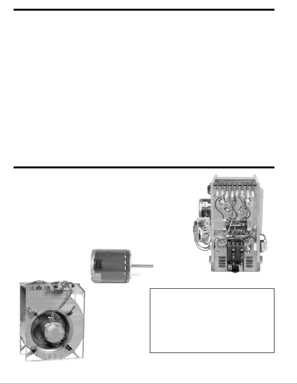
Engineering Features
Watt-restrictor
BLOWER
SECTION
X-13 (ECM)
MOTOR
GENERAL TERMS OF
LIMITED WARRANTY
Rheem®will furnish a replacement for any part of this product
which fails in normal use and service within the applicable
periods stated, in accordance with the terms of the limited
warranty.
Conditional Parts (Registration Required) ..Ten (10) Years
For Complete Details of the Limited Warranty, Including
Applicable Terms and Conditions, See Your Local Installer or
Contact the Manufacturer for a Copy.
Supplemental heat, provided by electric heating elements may be necessary in some areas
when heating requirements for indoor comfort exceed the capacity of the heat pump system.
When supplemental heat is required, units with the Watt Restrictor will restrict the amount of
supplemental electric heat that can be energized dependent on the heat output of the heat
pump (temperature of the air leaving the indoor heat pump coil).
The Watt-restrictor utilizes sensing devices in the unit to sense the air temperature leaving
the indoor coil and disengage unnecessary heating elements when that temperature is at
least 85°F [29°C]. (In this mode your system is controlled by the first stage of the wall thermostat.) This occurs only when the second stage of the wall thermostat calls for heat.
Since the heat output of the heat pump is dependent upon the outdoor air temperature, this
control performs the same function as a field installed outdoor thermostat.
An additional benefit of the Watt Restrictor is that it can sense a degradation in heat pump
performance due to causes other than outdoor temperature and react accordingly to bring
on more supplemental electric heat.
[ ] Designates Metric Conversions
Page 3
Rheem Heating, Cooling and Water Heating 3
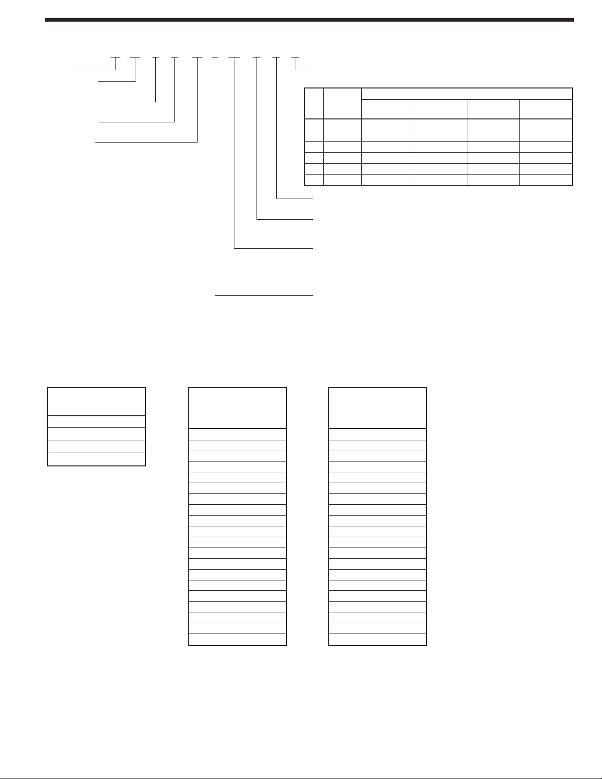
J00 N H D
Coil Code
A = No Coil
Airflow
Horizontal Multi-Position
Control
N = No Circuit Protection (Single Circuit)
S = Circuit Breaker (Single Circuit)
Electric Heat
00 = No Heat 14 = 14.0 kW
06 = 4.9 kW 18 = 17.5 kW
07 = 7.0 kW 21 = 21.0 kW
11 = 10.0 kW
Voltage
A = 115V-1-60
J = 208/240V-1-60
Model Identification
RBHP17
Rheem
Classification
B = Blower Unit
Application
H = Heat Pump Air Handler
Design Series
P = X-13 (ECM) Motor
Cabinet Size
17 = 17.5" [431.8 mm]
21 = 21.0" [533.4 mm]
24 = 24.5" [609.6 mm]
25 = 24.5" [635 mm]
Available Models
featuring R-22
Refrigerant
RBHP-17A00NHD
RBHP-17J06SHD
RBHP-17J07SHD
RBHP-17J11SHD
RBHP-21A00NHD
RBHP-21J06SHD
RBHP-21J07SHD
RBHP-21J11SHD
RBHP-21J14SHD
RBHP-24A00NHD
RBHP-24J06SHD
RBHP-24J07SHD
RBHP-24J11SHD
RBHP-24J14SHD
RBHP-24J18SHD
RBHP-25A00NHE
RBHP-25J11SHE
RBHP-25J14SHE
RBHP-25J18SHE
RBHP-25J21SHE
Available Models
(Without Coil)
RBHP-17J11SHA
RBHP-21J14SHA
RBHP-24J18SHA
RBHP-25J21SHA
Available Models
featuring R-410A
Refrigerant
RBHP-17A00NH1
RBHP-17J06SH1
RBHP-17J07SH1
RBHP-17J11SH1
RBHP-21A00NH2
RBHP-21J06SH2
RBHP-21J07SH2
RBHP-21J11SH2
RBHP-21J14SH2
RBHP-24A00NH4
RBHP-24J06SH4
RBHP-24J07SH4
RBHP-24J11SH4
RBHP-24J14SH4
RBHP-24J18SH4
RBHP-25A00NH7
RBHP-25J11SH7
RBHP-25J14SH7
RBHP-25J18SH7
RBHP-25J21SH7
—
Coil
Refrigerant
Code
Type
D R-22 RCHJ-24A1GH17
E R-22
1 R-410A RCHL-24A2GH17
2
R-410A
4 R-410A RCHL-48A1GH24
7 R-410A RCHL-60A1GH24
17
RCHJ-36A1GH2121RCHJ-48A1GH24
RCHL-36A1GH21
Cabinet Width
24
25
RCHJ-60A1GH24
Page 4
4 Rheem Heating, Cooling and Water Heating
[ ] Designates Metric Conversions
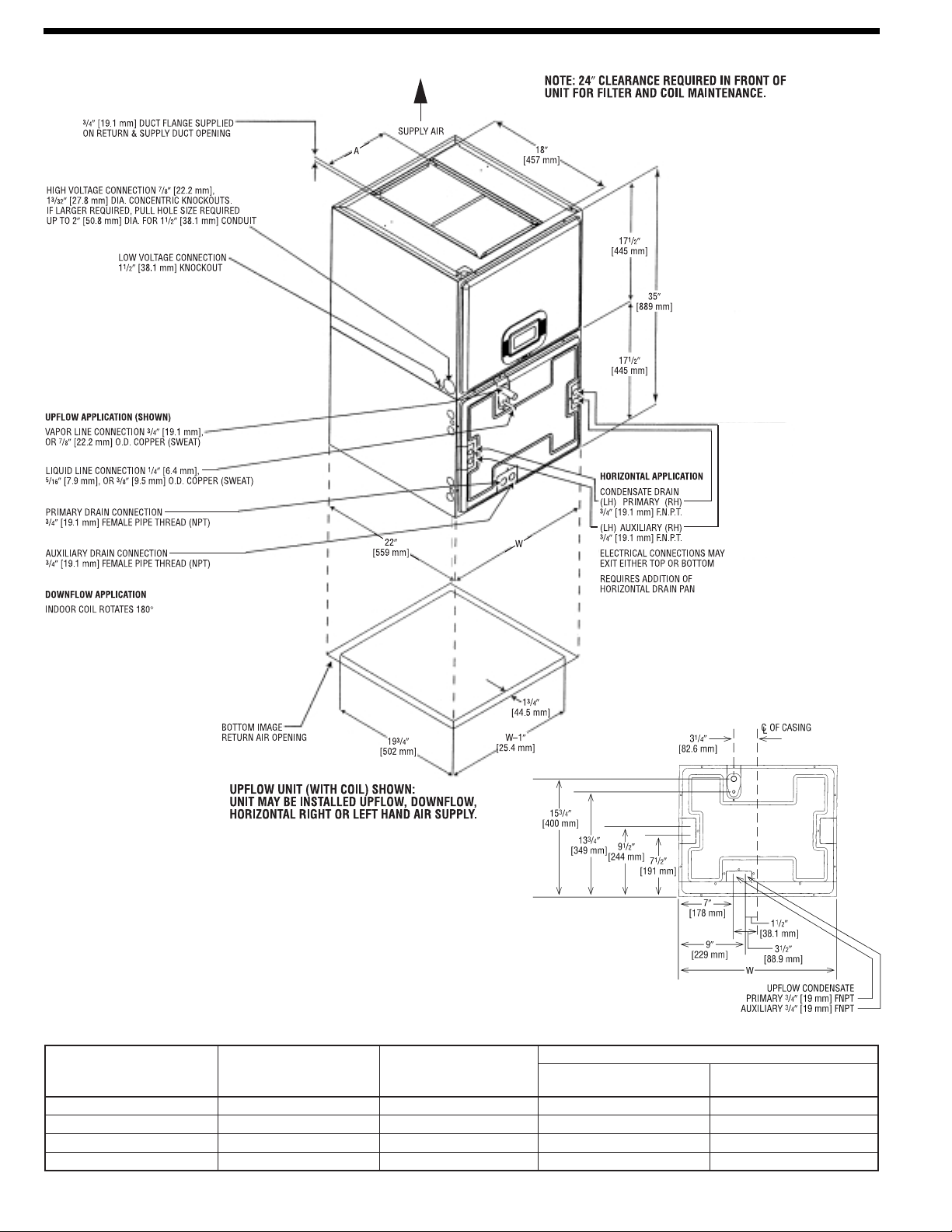
Unit Dimensions
Unit Dimensions & Weights
Model Number
Cabinet Size
17 171/2 [445] 79/16 [192] 92/99 [42/45]
21 21 [533] 97/16 [240] 109/117 [49/53]
24 241/2 [622] 113/4 [298] 125/134 [57/61]
25 241/2 [622] 113/4 [298] 125/134 [57/61] 88/97 [40/44]
Unit
Width
“W” In. [mm]
Supply
Duct
“A” In. [mm]
Unit Weight/Shipping Weight (Lbs.) [kg]
Unit With
Coil (Max. kW)
Unit Without
Coil (Max. kW)
66/75 [30/31]
79/87 [36/39]
88/97 [40/44]
Page 5

Rheem Heating, Cooling and Water Heating 5
UPFLOW DOWNFLOW
Airflow Directions
HORIZONTAL LEFT
HAND AIRFLOW
HORIZONTAL RIGHT
HAND AIRFLOW
NOTE: Coil and blower section are always in a draw through configuration.
Page 6

6 Rheem Heating, Cooling and Water Heating
Airflow Performance
Airflow performance data is based on cooling performance
with a coil and filter in place. Select performance table for
appropriate unit size, voltage and number of electric heaters to
be used. Make sure external static applied to unit allows operation within the minimum and maximum limits shown in table
below for both cooling and electric heat operation. For optimum
blower performance, operate the unit in the .2" to .5" in. W.C.
external static range. In general, the indoor motor speed tap
should be as shown in table for the appropriate cooling capacity
shown. Always check to make sure proper motor speed tap is
connected as units are shipped from the factory connected for
high speed operation (Speed Tap 5).
Airflow Operating Limits
NOTE: See Airflow Performance Data for Recommended Blower Motor Speed.
[ ] Designates Metric Conversions
Model Cabinet Size 17 21 24 25
Cooling BTUH
Cooling Tons Nominal
Heat Pump or Air Conditioning
Maximum Heat/Cool CFM [L/s]
(37.5 CFM [18 L/s]/1,000 BTUH)
(450 CFM [212 L/s]/Ton Nominal)
Heat Pump or Air Conditioning
Nominal Heat/Cool CFM [L/s]
(33.3 CFM [16 L/s]/1,000 BTUH)
(400 CFM [189 L/s]/Ton Nominal)
Heat Pump or Air Conditioning
Minimum Heat/Cool CFM [L/s]
(30.0 CFM [14 L/s]/1,255 BTUH)
(360 CFM [170 L/s]/Ton Nominal)
Maximum KW Electric Heating
& Minimum Electric Heat CFM [L/s]11560 [264]11560 [264]14900 [425]14900 [425]181220 [576]181220 [576]211460 [689]211460 [689]
Maximum Electric Heat Rise °F [°C] 85 [29] 85 [29] 70 [21] 70 [21] 65 [18] 65 [18] 65 [18] 65 [18]
18,000
1.5
675
[319]
600
[283]
540
[255]
24,000
2
900
[425]
800
[378]
720
[330]
30,000
2.5
1125
[531]
1000
[472]
900
[425]
36,000
3
1350
[637]
1200
[566]
1080
[510]
42,000
3.5
1575
[743]
1400
[661]
1260
[595]
48,000
4
1800
[850]
1600
[755]
1440
[680]
60,000
5
2025
[956]
1800
[850]
1620
[765]
60,000
[1062]
5
2250
2000
[944]
1800
[850]
Page 7

Rheem Heating, Cooling and Water Heating 7
Airflow Performance Data
NOTES:
X-13 (ECM) NOTES (X-13 (ECM) Motor Speed Changes)
X-13 (ECM) Motors require no voltage change between 208 and 240 volts.
If application exceeds 0.5" of static, adjust the motor speed to the high static speed as described below:
All X-13 (ECM) motors have 5 speed tabs. Speed tab 1 is for continuous fan. Speed 2 (Low Static) and speed tab 3 (High Static) are lower tonnage. Speed tab 4 (Low Static)
and Speed tab 5 (High Static) are for higher tonnage.
The lower static speed 2 (lower tonnage) and speed tab 4 (Higher tonnage) are used for external static below 0.5".
For external static exceeding 0.5", move the blue wire from the X-13 (ECM) motor to appropriate high static speed tab 3 (Lower tonnage) or speed tab 5 (Higher tonnage)
[ ] Designates Metric Conversions
Model
Cabinet
Size
Tonnage
1.5 Ton
Air Flow
Electric
Heaters
none
none
3 (max.)
3 (max.)
none
none
-17
none
none
3 (max.)
2.0 Ton
Air Flow
3 (max.)
none
none
none
none
4 (max.)
2.5 Ton
Air Flow
4 (max.)
none
none
-21
none
none
4 (max.)
3.0 Ton
Air Flow
4 (max.)
none
none
Blower Motor CFM [L/s] (Watts)/External Static Pressure—Inches W.C. [kPa] with filter and Indoor Coil
Nominal
Speed
Volts .10 [.02] .20 [.05] .30 [.07] .40 [.10] .50 [.12] .60 [.15] .70 [.17] .80 [.20] .90 [.23] 1.0 [.25]
Tap
2 208/240
3 208/240
2 208/240
3 208/240
2 115
3 115
4 208/240
5 208/240
4 208/240
5 208/240
4 115
5 115
2 208/240
3 208/240
2 208/240
3 208/240
2 115
3 115
4 208/240
5 208/240
4 208/240
5 208/240
4 115
5 115
659 [311]
(74)
790 [372]
(98)
649 [306]
(79)
773 [365]
(110)
651 [307]
(76)
776 [366]
(105)
844 [398]
(141)
958 [452]
(162)
834 [393]
(146)
946 [446]
(179)
846 [399]
(143)
964 [455]
(167)
1068 [504]
(138)
1187 [560]
(180)
1035 [488]
(143)
1157 [546]
(182)
1070 [504]
(138)
1138 [537]
(175)
1269 [598]
(207)
1397 [659]
(287)
1241 [585]
(222)
1366 [645]
(302)
1269 [598]
(207)
1370 [646]
(292)
625 [294]
(80)
759 [358]
(105)
615 [290]
(84)
736 [347]
(113)
627 [295]
(82)
743 [351]
(109)
819 [386]
(146
934 [440]
(172)
809 [831]
(150)
922 [435]
(189)
821 [387]
(148)
945 [446]
(178)
1041 [491]
(147)
1162 [548]
(188)
1007 [475]
(152)
1132 [534]
(192)
1043 [492]
(147)
1113 [525]
(186)
1236 [583]
(219)
1377 [649]
(307)
1208 [570]
(234)
1346 [635]
(313)
1236 [583]
(219)
1343 [634]
(302)
581 [274]
(84)
722 [340]
(113)
571 [269]
(88)
699 [330]
(118)
583 [275]
(86)
724 [342]
(118)
799 [377]
(155)
914 [431]
(176)
789 [372]
(159)
902 [426]
(193)
801 [378]
(157)
914 [431]
(181)
1001 [472]
(153)
1125 [530]
(192)
966 [455]
(158)
1095 [517]
(198)
1004 [473]
(153)
1075 [507]
(191)
1174 [554]
(226)
1346 [635]
(317)
1174 [554]
(241)
1315 [621]
(323)
1174 [554]
(226)
1309 [618]
(309)
539 [254]
(88)
687 [324]
(119)
529 [249]
(92)
677 [320]
(126)
541 [255]
(90)
687 [324]
(122)
764 [360]
(160)
888 [419]
(186)
754 [355]
(164)
876 [413]
(203)
766 [361]
(162)
888 [419]
(191)
972 [458]
(161)
1099 [518]
(200)
936 [441]
(169)
1069 [505]
(209)
974 [459]
(161)
1053 [497]
(203)
1149 [542]
(236)
1318 [622]
(320)
1149 [542]
(251)
1287 [608]
(331)
1149 [542]
(236)
1285 [607]
(319)
— — — — — —
650 [306]
(126)
640 [302]
(132)
658 [311]
(131)
855 [403]
(189)
843 [398]
(206)
861 [406]
(196)
1058 [499]
(208)
1028 [485]
(218)
1004 [474]
(210)
1291 [609]
(322)
1260 [595]
(341)
1258 [594]
(330)
615 [290]
(131)
— — — — — —
605 [286]
(141)
— — — — — —
617 [291]
(136)
— — — — — —
816 [380]
(210)
— — — — — —
804 [380]
(216)
— — — —
821 [387]
(205)
— — — — — —
1013 [478]
(215)
— — — — — —
983 [464]
(228)
— — — — — —
957 [451]
(216)
— — — — — —
1264 [596]
(319)
— — — — — —
1233 [582]
(346)
— — — — — —
1221 [576]
(336)
573 [270]
(139)
563 [266]
(146)
595 [281]
(144)
785 [370]
(204)
773 [365]
(221)
787 [372]
(210)
982 [463]
(223)
952 [449]
(239)
932 [440]
(226)
1234 [582]
(312)
1203 [568]
(358)
1182 [558]
(348)
552 [260]
(145)
542 [256]
(154)
555 [262]
(148)
760 [358]
(214)
748 [353]
(231)
761 [359]
(218)
951 [448]
(232)
921 [435]
(250)
901 [425]
(231)
1190 [561]
(326)
1159 [547]
(371)
1147 [542]
(357)
1155 [545]
1124 [530]
1117 [527]
507 [239]
(150)
497 [235]
(157)
517 [244]
(152)
708 [334]
(223)
696 [328]
(240)
— —
726 [342]
(220)
899 [424]
(234)
869 [410]
(255)
855 [404]
(242)
(351)
(381)
(366)
460 [217]
(155)
450 [212]
(162)
460 [217]
(162)
672 [317]
(226)
660 [311]
(243)
690 [326]
(230)
855 [403]
(237)
825 [389]
(262)
800 [378]
(252)
1126 [531]
(368)
1095 [517]
(387)
1080 [510]
(375)
Page 8

8 Rheem Heating, Cooling and Water Heating
Airflow Performance Data (cont.)
NOTES:
X-13 (ECM) NOTES (X-13 (ECM) Motor Speed Changes)
X-13 (ECM) Motors require no voltage change between 208 and 240 volts.
If application exceeds 0.5" of static, adjust the motor speed to the high static speed as described below:
All X-13 (ECM) motors have 5 speed tabs. Speed tab 1 is for continuous fan. Speed 2 (Low Static) and speed tab 3 (High Static) are lower tonnage. Speed tab 4 (Low Static)
and Speed tab 5 (High Static) are for higher tonnage.
The lower static speed 2 (lower tonnage) and speed tab 4 (Higher tonnage) are used for external static below 0.5".
For external static exceeding 0.5", move the blue wire from the X-13 (ECM) motor to appropriate high static speed tab 3 (Lower tonnage) or speed tab 5 (Higher tonnage)
[ ] Designates Metric Conversions
Model
Cabinet
Size
Tonnage
3.5 Ton
Air Flow
Electric
Heaters
none
none
5 (max.)
5 (max.)
none
none
-24
none
none
5 (max.)
4.0 Ton
Air Flow
5 (max.)
none
none
none
none
5 (max.)
5 (max.)
-25
5.0 Ton
Air Flow
none
none
none
5 (max.)
none
Blower Motor CFM [L/s] (Watts)/External Static Pressure—Inches W.C. [kPa] with filter and Indoor Coil
Nominal
Speed
Volts .10 [.02] .20 [.05] .30 [.07] .40 [.10] .50 [.12] .60 [.15] .70 [.17] .80 [.20] .90 [.23] 1.0 [.25]
Tap
2 208/240
3 208/240
2 208/240
3 208/240
2 115
3 115
4 208/240
5 208/240
4 208/240
5 208/240
4 115
5 115
2 208/240
3 208/240
2 208/240
3 208/240
2 115
3 115
4 or 5 208/240
4 or 5 208/240
4 or 5 115
1438 [678]
(205)
1568 [740]
(279)
1414 [667]
(230)
1548 [730]
(304)
1448 [683]
(205)
1559 [735]
(294)
1640 [773]
(311)
1789 [844]
(413)
1613 [761]
(331)
1759 [830]
(433)
1642 [774]
(311)
1811 [854]
(423)
1872 [883]
(373)
2075 [979]
(497)
1831 [854]
(393)
2043 [964]
(517)
1872 [883]
(373)
2075 [979]
(497)
2102 [992]
(550)
2070 [976]
(560)
2102 [992]
(550)
1409 [664]
(217)
1538 [725]
(290)
1384 [653]
(242)
1518 [716]
(316)
1419 [669]
(217)
1527 [720]
(308)
1604 [757]
(326)
1762 [831]
(427)
1574 [742]
(346)
1732 [817]
(447)
1606 [757]
(326)
1791 [845]
(436)
1837 [866]
(393)
2036 [960]
(511)
1795 [847]
(413)
2004 [945]
(531)
1837 [866]
(393)
2036 [960]
(511)
2072
[977](568)
2040
[962](578)
2072
[977](568)
1375 [648]
(229)
1507 [711]
(303)
1350 [637]
(254)
1487 [701]
(328)
1385 [653]
(229)
1497 [706]
(322)
1587 [748]
(335)
1731 [816]
(433)
1557 [734]
(355)
1701 [802]
(453)
1589 [749]
(335)
1760 [830]
(451)
1798 [848]
(407)
2017 [951]
(533)
1756 [828]
(427)
1985 [936]
(553)
1798 [848]
(407)
2017 [951]
(533)
2042 [963]
(584)
2010 [948]
(594)
2042 [963]
(584)
1341 [632]
(252)
1471 [694]
(313)
1315 [620]
(277)
1451 [684]
(338)
1351 [637]
(252)
1466 [691]
(335)
1559 [735]
(376)
1699 [801]
(449)
1529 [721]
(396)
1669 [787]
(469)
1561 [736]
(376)
1730 [816]
(464)
1763 [832]
(419)
1984 [936]
(553)
1720 [811]
(439)
1951 [920]
(573)
1763 [832]
(419)
1984 [936]
(553)
2011 [949]
(593)
1979 [933]
(613)
2011 [949]
(593)
— — — — — —
1435 [677]
1415 [667]
1431 [675]
1667 [786]
1637 [772]
1700 [802]
1944 [917]
1912 [901]
1944 [917]
1974 [931]
1942 [916]
1974 [931]
1403 [662]
(333)
— — — — — —
1383 [653]
(358)
— — — — — —
1378 [650]
(349)
— — — — — —
1635 [771]
(462)
— — — — — —
1605 [757]
(482)
— — — —
1669 [787]
(479)
— — — — — —
1910 [901]
(563)
— — — — — —
1878[886]
(583)
— — — — — —
1910 [901]
(563)
1949 [919]
(610)
1917 [904]
(620)
1949 [919]
(610)
(338)
(368)
(367)
(482)
(502)
(492)
(582)
(602)
(582)
(631)
(641)
(631)
1362 [642]
(358)
1342 [633]
(388)
1349 [636]
(379)
1602 [756]
(498)
1572 [741]
(518)
1606 [757]
(516)
1889 [891]
(599)
1857 [876]
(619)
1889 [891]
(599)
1916 [904]
(644)
1884 [889]
(654)
1916 [904]
(644)
1318 [622]
(365)
1298 [612]
(395)
1306 [606]
(393)
1546 [729]
(516)
1516 [715]
(536)
1573 [742]
(529)
1846 [871]
(617)
1814 [856]
(637)
1846 [871]
(617)
1884 [889]
(662)
1852 [874]
(672)
1884 [889]
(662)
1287 [607]
1267 [597]
1271 [599]
1515 [715]
1485 [700]
1538 [725]
1805 [851]
1805 [851]
1851 [873]
1819 [858]
1851 [873]
(374)
(409)
(406)
(529)
(549)
— —
(542)
(626)
1773 836]
(646)
(626)
(669)
(679)
(669)
1250 [589]
(405)
1230 [580]
(455)
1250 [589]
(417)
1465 [691]
(542)
1435 [677]
(562)
1462 [689]
(555)
1783 [841]
(638)
1751[826]
(658)
1783 [841]
(638)
1810 [854]
(692)
1778 [839]
(702)
1810 [854]
(692)
Page 9

Rheem Heating, Cooling and Water Heating 9
Blower Motor Electrical Data: A Voltage (115V)
Electric Heat Electrical Data
Blower Motor Electrical Data: J Voltage (208/240V)
Supply circuit protective devices may be fuses or “HACR” type circuit breakers. Largest motor load is included in single circuit and circuit 1 multiple circuit. If non-standard fuse size is
specified, use next size larger standard fuse size.
[ ] Designates Metric Conversions
Model
Size/Elec.
Designation
RBHP-17A00NH* 115 1 60 1/3 [249] 300-1100 5 3.3 5.0 15
RBHP-21A00NH* 115 1 60 1/2 [373] 300-1100 5 5.0 7.0 15
RBHP-24A00NH* 115 1 60 3/4 [559] 300-1100 5 5.8 8.0 15
RBHP-25A00NH* 115 1 60 3/4 [559] 300-1100 5 7.7 10.0 15
Voltage Phase Hertz HP [W] RPM Speeds
Circuit
Amps.
Minimum
Circuit
Ampacity
Model
Size/Elec.
Designation
RBHP-17J00NH* 208/240 1 60 1/3 [249] 300-1100 5 2.0 3.0 15
RBHP-21J00NH* 208/240 1 60 1/2 [373] 300-1100 5 3.1 4.0 15
RBHP-24J00NH* 208/240 1 60 3/4 [559] 300-1100 5 4.2 6.0 15
RBHP-25J00NH* 208/240 1 60 3/4 [559] 300-1100 5 5.7 8.0 15
Voltage Phase Hertz HP [W] RPM Speeds
Circuit
Amps.
Minimum
Circuit
Ampacity
Maximum
Circuit
Protector
Maximum
Circuit
Protector
Model
Elec./KW
Designation
RBHP-17J06SH*
RBHP-17J07SH*
RBHP-17J11SH*
RBHP-21J06SH*
RBHP-21J07SH*
RBHP-21J11SH*
RBHP-21J14SH*
RBHP-24J06SH*
RBHP-24J07SH*
RBHP-24J11SH*
RBHP-21J14SH*
RBHP-21J18SH*
RBHP-25J11SH*
RBHP-25J14SH*
RBHP-25J18SH*
RBHP-25J21SH*
Heater
KW
Volts
208/240
3.7/4.9
5.3/7.0 2/3.5
13.2/17.5 5/3.5
5.3/7.0
13.2/17.5 5/3.5
15.0/20.0 6/3.3
PH/HZ
1/60 Single Circuit 25/29
1/60 Single Circuit 35/395.3/7.0 2/3.5 27.5/31.2 40/40
1/60 Single Circuit 48/557.5/10.0 3/3.3 38.1/43.7 50/60
1/60 Single Circuit 27/303.7/4.9 2/2.5 20.9/23.5 30/30
1/60 Single Circuit 36/415.3/7.0 2/3.5 28.6/32.3 40/45
1/60 Single Circuit 49/567.5/10.0 3/3.3 39.2/44.8 50/60
1/60
1/60 Single Circuit 28/313.7/4.9 2/2.5 22.0/24.6 30/35
1/60 Single Circuit 38/425.3/7.0 2/3.5 29.7/33.4 40/45
1/60 Single Circuit 51/587.5/10.0 3/3.3 40.3/45.9 60/60
1/60
1/60
1/60 Single Circuit 53/607.5/10.0 3/3.3 41.8/47.4 60/60
1/60
1/60
1/60
Heater
No./KW & 240V
2/2.5
2/3.5
3/3.5
Type Supply Circuit
Single Circuit
Multiple Circuit
Single Circuit 68/7710.5/14.0 4/3.5 54.1/61.4 70/80
Multiple Ckt. 1 36/415.3/7.0 2/3.5 28.6/32.3 40/45
Multiple Ckt. 2 32/375.3/7.0 2/3.5 25.5/29.2 35/40
Single Circuit 69/7910.5/14.0 4/3.5 55.2/62.5 70/90
Multiple Ckt. 1 38/425.3/7.0 2/3.5 29.7/33.4 40/45
Multiple Ckt. 2 32/37
Single Circuit 85/97
Multiple Ckt. 1 38/425.3/7.0 2/3.5 29.7/33.4 40/45
Multiple Ckt. 2 48/557.9/10.5 3/3.5 38.0/43.8 50/60
Single Circuit 71/8110.5/14.0 4/3.5 56.7/64.0 80/90
Multiple Ckt. 1 39/445.3/7.0 2/3.5 31.2/34.9 40/50
Multiple Ckt. 2 32/37
Single Circuit 87/99
Multiple Ckt. 1 39/445.3/7.0 2/3.5 31.2/34.9 40/45
Multiple Ckt. 2 48/557.9/10.5
Single Circuit 98/112
Multiple Ckt. 1 53/607.5/10.0 3/3.3 41.8/47.4 60/70
Multiple Ckt. 2 46/537.5/10.0 3/3.3 36.1/41.7 50/60
Circuit
Amps.
19.8/22.4
25.5/29.2 35/40
67.7/77.1 90/100
25.5/29.2 35/40
69.2/78.6 90/100
38.0/43.8 50/60
77.8/89.0 100/125
Minimum
Circuit
Ampacity
Maximum
Circuit
Protector
25/30
Page 10

10 Rheem Heating, Cooling and Water Heating
Combustible Floor Base for Downflow Installations
ACCESSORIES—KITS—PARTS
• Combustible Floor Base RXBB-AA for downflow applications.
• Jumper Bar Kit 3 Ckt. to 1 Ckt. RXBJ-A31 is used to convert
single phase multiple three circuit units to a single supply
circuit. Kit includes cover and screw for line side terminals.
• Jumper Bar Kit 2 Ckt. to 1 Ckt. RXBJ-A21 is used to convert
single phase multiple two circuit units to a single supply circuit.
Kit includes cover and screw for line side terminals.
• Note: No jumper bar kit is available to convert three phase
multiple two circuit units to a single supply circuit.
••FInger Safe Circuit Breaker Cover—Part Number
45-23203-01. One is required for each circuit breaker pole,
if jumper bar is removed to provide multiple supply circuits.
• Evaporator Horizontal Drain Pan Model RXBD-CB: all
unit sizes.
• External Auxiliary Horizontal Drain Pan. RXBM-AA06—Fits
all models.
• Replacement Filters
Model Cabinet Size Filter Size In. [mm] Part Number
17 16.25 x 21 [413 x 533] 54-23217-02
21 19.75 x 21 [502 x 533] 54-23217-03
24 23.25 x 21 [591 x 533] 54-23217-04
25 23.25 x 21 [591 x 533] 54-23217-04
[ ] Designates Metric Conversions
• Thermostats
Electrical Wiring
Power Wiring
• Field wiring must comply with the National Electrical Code
(C.E.C. in Canada) and any applicable local ordinance.
• Supply wiring must be 75°C minimum copper conductors only.
• See electrical data for product Ampacity rating and Circuit
Protector requirement.
Grounding
• This product must be sufficiently grounded in accordance with
National Electrical Code (C.E.C. in Canada) and any applicable
local ordinance.
• A grounding lug is provided.
Model Cabinet Size
All Models RXBB-AA 143/8" [365] 205/8" [524]
Combustible Floor
Base Model Number
Opening Front of Unit
“W” Width-Inches [mm]
Opening Side of Unit
“D” Depth-Inches [mm]
Page 11

Rheem Heating, Cooling and Water Heating 11
NOTES
Page 12

Before proceeding with installation, refer
to installation instructions packaged
with each model, as well as complying
with all Federal, State, Provincial, and
Local codes, regulations, and practices.
Rheem Heating,
Cooling and
Water Heating
P.O. Box 17010, Fort Smith, AR 72917
“In keeping with its policy of continuous progress and product improvement, Rheem reserves the right to make changes without notice.”
PRINTED IN U.S.A. 7-09 DC FORM NO. H11-527 REV. 5
Supersedes Form No. H11-527 Rev. 4
 Loading...