

Page 1
FORM NO. H11-521 REV. 5
Supersedes Form No. H11-521 Rev. 4
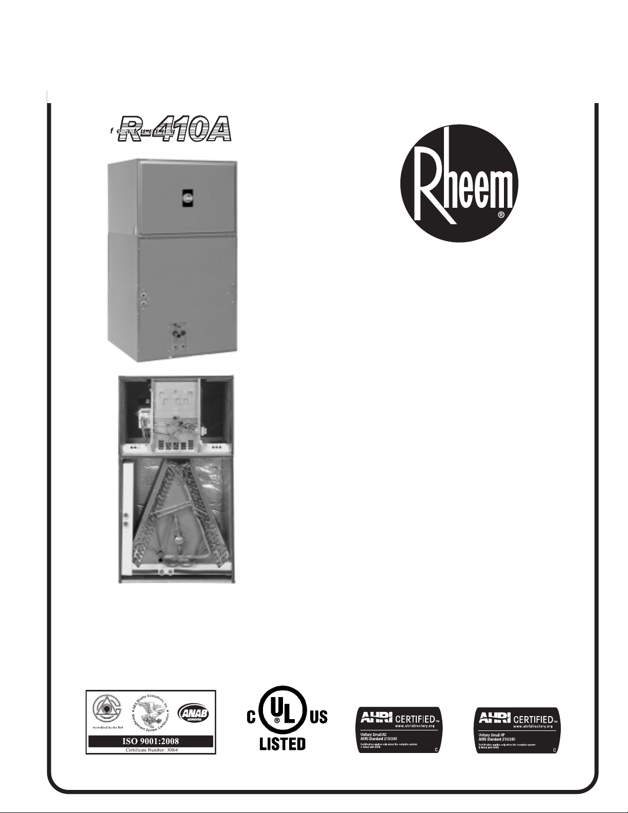
AIR HANDLERS
RBHM- SERIES
AIR HANDLERS
AND FAN COIL UNIT
Features
■ Versatile 3-way convertible design for upflow, horizontal
left and horizontal right.
■ Available from the factory in upflow and horizontal left
configurations.
■ Nominal airflow up to 1.0" external static pressure.
■ Standard factory installed high-efficiency coils.
■ The blower box is made of sturdy double wall construc-
tion with .5 inch [12.7 mm] of foil faced insulation for
excellent sound and insulating characteristics.
■ Designed for use with exterior high-static filters.
■ Circuit breaker (standard on units with more than 11 kW)
meets U.L. and cUL requirements for service disconnect.
■ Factory installed electric heat provides exact heat for
indoor comfort over a variety of applications.
■ Dip switch settings for selectable, customized cooling air-
flow over a wide variety of applications.
■ On-demand dehumidification-terminal that adjusts airflow to
help control humidity for unsurpassed comfort in cooling mode.
Page 2
2 Rheem Heating, Cooling and Water Heating
RBHM- Series
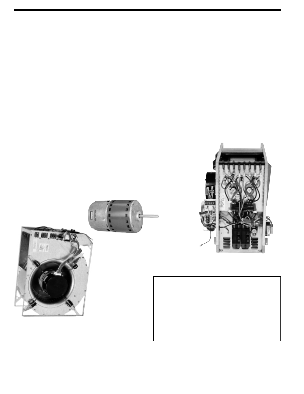
■ Quiet, energy efficient ECM motor technology providing nomi-
nal airflow to 1.0 inch [25 kPa] of external static pressure.
■ Interface board with dip switches conveniently located in the
blower compartment allows for precise, field selectable airflow
to meet the requirements of particular applications.
■ Selectable continuous fan “on” options.
■ Attractive pre-painted cabinet exterior.
■ The blower box has rugged double wall steel cabinet construc-
tion, designed for added strength and versatility.
■ .5" foil faced insulation mechanically retained in blower
compartment.
■ Four leg, rubber insulated wire motor mount.
■ Circuit breakers standard on 1-phase models above 11 kW
and optional on models with 11 kW or less.
■ Models supplied with circuit breakers meet UL and CUL
requirements as a service disconnect switch.
■ Provisions for field electrical connections from either side of air
handler cabinet.
■ Tab lock blower housing with integrated electric heaters, con-
trols, motor and blower. Slide out design for service and maintenance convenience.
[ ] Designates Metric Conversions
■ Exclusive dependable Incoloy sheath type electric heating
elements located in the blower housing provide mixed warm
air.
■ Field convertible for vertical upflow, horizontal left hand or right
hand air supply.
■ Indoor coil design provides low air side pressure drop and
high performance. All coils come with PVC condensate elbow
standard.
■ All indoor coils have copper tubing and aluminum fins.
■ Molded polymer corrosion resistant condensate drain pan is
provided on all indoor coils.
■ Both supply and return duct flanges provided as standard on
air handler cabinet.
■ Connection points for both high voltage and low voltage control
wiring inside air handler cabinet.
■ Concentric knockouts are provided for power connection to
cabinet. Installer may pull desired hole size up to 2 inches
[51 mm] for 1
1
/2 inch [38 mm] conduit.
■ Front refrigerant and drain connections.
Engineering Features
BLOWER
SECTION
ECM
MOTOR
GENERAL TERMS OF
LIMITED WARRANTY
Rheem will furnish a replacement for any part of this
product which fails in normal use and service within the
applicable periods stated, in accordance with the terms of
the limited warranty.
Limited Parts Warranty ........................................10 years.*
For Complete Details of the Limited Warranty, Including
Applicable Terms and Conditions, See Your Local Installer or
Contact the Manufacturer for a Copy.
Page 3
Rheem Heating, Cooling and Water Heating 3
Model Identification
NOTES: 1) RBHM Air Handler cannot be ordered without coil.
2) Electrical heat designation: set electric heat data for actual heater kW represented by number above.
3) Electric heater BTUH = (heater watts + motor watts) x 3.412 (See airflow table for motor watts).
4)
†
Air Handlers with A-Coils do not come with a factory installed air filter. External filter rack or other means of filtration is required.
[ ] Designates Metric Conversions
R B H M 17 J 11 S M Q
Rheem Blower
Unit
Type
Unit
H = Air
Handler
Design
Series
Cab.
Width
17
24
25
26
Electrical
Designations
J = 208/240V,
1PH, 60HZ
Electrical Heat (KW) Designation
See Electrical Heat Data for
Actual KW at 208 Volts.
00 = No Heat
06 = 4.9 kW
07 = 7.0 kW
11 = 10.0 kW
14 = 14.0 kW
Control
Designation
N = No Circuit
Breakers Single
Supply Circuit
S = Circuit Breaker(s)
Single Supply
Circuit
Airflow
Direction
M = Multiposition
Coil
Code
Additional
Inform.
1) Motor H.P. [W]
2) Blower CFM [L/s]
1st/2nd Stage
3) Blower Wheel
Dia./Width [mm]
4) Filter Size
Width/Length [mm]
5) Outdoor
Unit Size
17 =
17.5"
24 =
24.5"
25 =
24.5"
00, 06, 07, 11
J
N
Q = RCQD-2417AS
06, 07, 11 S
00, 07, 11 N
J
R = RCQD-3624AS
07, 11, 14 S
1) 1/3 H.P. [249]
2) 600/800 CFM
[283/378]
29
13
32 x 3
/
3) 11
[302 x 96]
†
4) N/A
5) -024
1) 1/2 H.P. [373]
2) 900/1200 CFM
[425/566]
29
3) 11
/32 x 71/8
[302 x 181]
†
4) N/A
5) -036
16
/
M = Multiposition
00, 11 N
J
S= RCQD-4824AS
11, 14, 18 S
1) 3/4 H.P. [559]
2) 1200/1600 CFM
[566/755]
29
3) 11
/32 x 91/2
[302 x 241]
†
4) N/A
5) -048
11 N
26 =
24.5"
J
11, 14, 18, 21 S
1) 1 H.P.
2) 1275/1700 CFM
[602/802]
T= RCQD-6024AS
29
3) 11
[302 x 241]
4) N/A
/32 x 91/2
†
5) -060
Page 4

4 Rheem Heating, Cooling and Water Heating
Unit Dimensions
Unit Dimensions & Weights
[ ] Designates Metric Conversions
( ) Designates Unit with Double Coil Cabinet
AIRFLOW
FRONT VIEW
SIDE VIEW
3
/4 [19 mm] DUCT FLANGE
SUPPLIED ON RETURN AND
SUPPLY DUCT OPENING
HIGH VOLTAGE CONNECTION
7
/8 [22 mm], 13/32 [28 mm] DIA.
CONCENTRIC KNOCK OUTS. IF
LARGER REQUIRED, PULL HOLE
SIZE REQ'D UP TO 2 [51 mm] DIA.
FOR 11/2 [38 mm] CONDUIT
LOW VOLTAGE CONNECTION
1
/2 [12.5 mm] KNOCK OUT
UPFLOW UNIT SHOWN:
UNIT MAY BE INSTALLED UPFLOW,
HORIZONTAL RIGHT OR LEFT HAND
AIR SUPPLY.
A
18
[457 mm]
171/2
[445 mm]
28
[711 mm]
AIRFLOW
DIRECTION
1
/2
45
[1156 mm]
HORIZONTAL DRAIN
KNOCKOUT RIGHT AIRFLOW
PRIMARY HORIZONTAL
DRAIN LEFT AIRFLOW
AUXILIARY HORIZONTAL
DRAIN LEFT AIRFLOW
BOTTOM IMAGE
RETURN AIR OPENING
22
[559 mm]
20
[508 mm]
W
W-1
[25 mm]
AUXILIARY VERTICAL DRAIN
PRIMARY VERTICAL DRAIN
3
1
/4
[44 mm]
Model Number
RBHM-
(with RCQD coil)
17
24 241/2 [622] 113/4 [298] 720 190/199 [86/90]
25
Unit
Width
“W” In. [mm]
171/2 [445] 79/16 [192]
241/2 [622] 113/4 [298]
241/2 [622] 113/4 [298]
Supply
Duct
“A” In. [mm]
Nominal Coil Airflow Stage
1st 2nd
ODD ODD
450 136/143 [62/65]
960 1280 196/205 [89/93]
1050 1350 197/206 [89/93]
Normal
600
900
1200
1275 170026
600
960
Normal
800
1200
1600
Unit Weight/Shipping
Weight (Lbs.) [kg]
Unit With
Coil (Max. KW)
Page 5

Rheem Heating, Cooling and Water Heating 5
Airflow Performance
Airflow performance data is based on cooling performance
with dry coil and filter in place. Select performance table for
appropriate unit size, voltage and number of electric heaters to
be used. Make sure external static applied to unit allows operation within the minimum and maximum limits shown in table
below for both cooling and electric heat operation. For optimum
blower performance, operate the unit in the .2" to .5" in. W.C.
external static range. In general, the indoor motor speed tap
should be as shown in table for the appropriate cooling capacity shown. Always check to make sure proper motor speed tap
is connected as units are shipped from the factory connected
for high speed operation.
Airflow Performance Data
IMPORTANT: Observe airflow operating limits. Do not operate above 1.0 in. W.C. system external static.
[ ] Designates Metric Conversions
Model
Cabinet
RBHM17
RBHM24
Size
2 ton
-17
3 ton
-24
Electric
Heaters
3 (Max.)
None
3 (Max.)
None
Blower Motor
Thermostat
Volts
208
230
208
230
208
230
208
230
Input
Y1
Y2
Y1
Y2
Y1
Y2
Y1
Y2
Y1
Y2
Y1
Y2
Y1
Y2
Y1
Y2
0.1 [.02] 0.2 [.05] 0.3 [.07] 0.4 [.10] 0.5 [.12] 0.6 [.15] 0.7 [.17] 0.8 [.20] 0.9 [.23] 1.0 [.25]
585 [276] 588 [278] 589 [278] 590 [278] 589 [278] 588 [278] 585 [276] 582 [275] 577 [272] 572 [270]
CFM
RPM 552 610 667 725 782 840 898 955 1013 1070
WATTS 59 76 93 110 127 144 161 179 197 214
CFM
792 [374] 795 [375] 797 [376] 798 [377] 797 [376] 795 [375] 791 [373] 786 [371] 779 [368] 771 [364]
RPM 684 731 777 824 870 917 963 1009 1056
WATTS 135 156 177 197 218 238 259 279 299 319
CFM
585 [276] 590 [278] 593 [280] 595 [281] 595 [281] 594 [280] 592 [279] 589 [278] 585 [276] 579 [273]
RPM 557 615 673 731 788 846 904 961 1019
WATTS 67 82 98 114 131 148 166 184 203 222
CFM
786 [371] 790 [373] 793 [374] 795 [375] 795 [375] 794 [375] 792 [374] 788 [372] 783 [370] 777 [367]
RPM 664 713 762 811 861 910 959 1009 1058
WATTS
CFM
RPM 549 605 660 716 772 828
WATTS
CFM
RPM 681 724 768 812 855 899 943 986 1030
WATTS 136 156 175 194 213 232 251 270 288 307
CFM
RPM 545 601 657 712 768 824 879 935 991
WATTS 55 74 93 111 129 146 163 179 195 210
CFM
RPM 677
WATTS
CFM
RPM 496 551 607 663 718 774
WATTS
CFM
RPM 544 598 653 707 762 816 871 925 980
WATTS 115 154 192 229 264 298
CFM
RPM 489 547 604 661 719 776 833 890 948
WATTS 74 98 122 147 172 198 223 249 275 301
CFM
RPM 550
WATTS 124 162 198 234
CFM
RPM
WATTS
CFM
RPM 514 564 614 664 714 764 813 863 913
WATTS 126 153 180 207 235 263 292 321 351 381
CFM
RPM 448 503 559 614 670 725 780 836 891
WATTS 63 83 104 126 149 172 196 222 247 274
CFM
RPM
WATTS 124 151 177 205
131 151 172 193 214 236 258 281 304 328
606 [286] 609 [287] 611 [288] 611 [288] 609 [287] 606 [286] 602 [284] 596 [281] 589 [278] 580 [274]
60 77 95 112 129 146 163 179 196 212
819 [387] 821 [387] 822 [388] 821 [387] 819 [387]
613 [289] 614 [290] 614 [290] 613 [289] 611 [288] 608 [287] 605 [286] 600 [283] 595 [281] 589 [278]
819 [387] 821 [387] 823 [388] 822 [388]
139 156 173 191
870 [411] 876 [413] 881 [416] 883 [417] 883 [417] 881 [416] 877 [414] 871 [411] 863 [407] 852 [402]
71 95 119 143 167 191 215 239 264 288
1147 [541] 1163 [549] 1175 [555] 1183 [558] 1187 [560]
867 [409] 874 [412] 880 [415] 884 [417] 886 [418] 885 [418] 883 [417] 879 [415] 872 [412] 864 [408]
1139 [538] 1158 [547] 1172 [553] 1182 [558]
880 [415] 888 [419] 895 [422] 900 [425] 903 [426] 906 [428] 906 [428] 905 [427] 903 [426] 899 [424]
451 506
65 87 108 129 151 172 194 215 236 258
1127 [532] 1151 [543] 1171 [553] 1186 [560] 1196 [564]
881 [416] 891 [421] 899 [424] 906 [428] 911 [430] 914 [431] 916 [432] 916 [432] 914 [431] 910 [429]
1134 [535] 1158 [547] 1178 [556] 1194 [564]
509
721
604
559
CFM [L/s] (Watts)/External Static Pressure—Inches W.C. [kPa]
765
657
560
610
809 853 897 941 985 1029
710 764 817 870 924 977
615 670 725
660 711 761 812 862 913
1102
1077
1107
884
815 [385] 809 [382] 802 [379] 793 [374] 782 [369]
821 [387] 817 [386] 812 [383] 806 [380] 798 [377] 789 [372]
210
1189 [561] 1191 [562] 1189 [561] 1184 [559] 1174 [554] 1160 [547]
269
1205 [569] 1212 [572] 1214 [573] 1213 [572] 1206 [569] 1196 [564]
233
230 249 270 291 313
829
1187 [560] 1183 [558] 1175 [555] 1163 [549] 1148 [542]
331 362 391 419
302 334 365 395 424
779
1202 [567] 1204 [568] 1201 [567] 1194 [564] 1183 [558]
262 292 323 354 386
940 996
885 941
834 889
1052
1074
1046
1073
996
1034
1005
1030
944
963
947
964
Page 6

6 Rheem Heating, Cooling and Water Heating
Airflow Performance Data
IMPORTANT: Observe airflow operating limits. Do not operate above 1.0 in. W.C. system external static.
[ ] Designates Metric Conversions
Model
Size
4 ton
-25
5 ton
-26
Electric
Heaters
6 (Max.)
None
6 (Max.)
None
Cabinet
RBHM25
RBHM26
Blower Motor
Thermostat
Volts
208
230
208
230
208
230
208
230
Input
Y1
WATTS
Y2
WATTS 235 286 333 378 420 460
Y1
WATTS 126 162 196 230 264 296 328 359 389 419
Y2
WATTS 241 287 332 376
Y1
WATTS
Y2
WATTS 220 252 284 318 352 386 421 457 494 531
Y1
WATTS 117 140 165 191 217 245 274 303 334 365
Y2
WATTS 216 250 285 321
Y1
WATTS
Y2
WATTS 303 339 376 414 451 488
Y1
WATTS 161 186 212 241 271 303 337 372 409 448
Y2
WATTS 311 350 389 426
Y1
WATTS
Y2
WATTS 288 316 346 375 406 437 469 502 536 570
Y1
WATTS 133 158 184 211 239 267 296 325 356 387
Y2
WATTS 287 318 349 380
0.1 [.02] 0.2 [.05] 0.3 [.07] 0.4 [.10] 0.5 [.12] 0.6 [.15] 0.7 [.17] 0.8 [.20] 0.9 [.23] 1.0 [.25]
CFM
1182 [558] 1184 [559] 1184 [559] 1181 [557] 1177 [555] 1170 [552] 1160 [547] 1149 [542] 1134 [535] 1118 [528]
RPM 545 599 653 708 762 816
CFM
RPM 634 680 726 772 818 864 910 956 1002
CFM
RPM 546 600 654 709 763 818 872 926 981
CFM
RPM 630
CFM
RPM
CFM
RPM 578 621 664 707 750 792 835 878 921
CFM
RPM 480 532 584 636 688 740 792 844 896
CFM
RPM
CFM
RPM 543 598 652 706 761 815
CFM
RPM 659 701 744 786 829 871 914 957 999
CFM
RPM 540 595 649 704 758 813 867 922 976
CFM
RPM 669
CFM
RPM
CFM
RPM 630 668 705 742 780 817 854 892 929
CFM
RPM 505 555 605 654 704 754 804 854 903
CFM
RPM
133 162 193 223 255 286 319 352 385 419
1554 [733] 1567 [740] 1576 [744] 1583 [747] 1586 [749]
1186 [560] 1190 [562] 1191 [562] 1190 [562] 1185 [559] 1179 [556] 1169 [552] 1157 [546] 1143 [539] 1125 [531]
1566 [739] 1579 [745] 1588 [749] 1595 [753]
1200 [566] 1202 [567] 1204 [568] 1204 [568] 1204 [568] 1203 [568] 1201 [567] 1198 [565] 1195 [564] 1191 [562]
478
117 139 162 186 212 240 269 299 331 364
1558 [735] 1571 [741] 1581 [746] 1590 [750] 1597 [754]
1202 [567] 1205 [569] 1207 [570] 1207 [570] 1207 [570] 1206 [569] 1204 [568] 1201 [567] 1197 [565] 1192 [563]
1566 [739] 1575 [743] 1583 [747] 1590 [750]
583
1276 [602] 1278 [603] 1276 [602] 1272 [600] 1264 [597] 1252 [591] 1238 [584] 1220 [576] 1198 [565] 1174 [554]
144 173 203 233 265 298 331 366 402 439
1707 [806] 1706 [805] 1704 [804] 1699 [802] 1693 [799]
1289 [608] 1288 [608] 1284 [606] 1277 [603] 1268 [598] 1255 [592] 1240 [585] 1223 [577] 1202 [567] 1179 [556]
1707 [806] 1706 [805] 1704 [804] 1700 [802]
1287 [607] 1285 [606] 1282 [605] 1279 [604] 1276 [602] 1273 [601] 1269 [599] 1266 [597] 1262 [596] 1258 [594]
496 547
130 152 176 202 229 258 289 321 356 391
1692 [800] 1695 [800] 1697 [801] 1699 [802] 1699 [802]
1294 [611] 1291 [609] 1288 [608] 1285 [606] 1281 [605] 1278 [603] 1274 [601] 1270 [599] 1266 [597] 1261 [595]
1699 [802] 1703 [804] 1705 [805] 1706 [805]
615
676
530
625
710
655
CFM [L/s] (Watts)/External Static Pressure—Inches W.C. [kPa]
722
582
668
751
597
695
769 815 861 907 954 1000
633 685 737
711 753 796 839 881 924
793 834 876 917 959 1000
648 699 750
735 775 815 855 895 935
871
1586 [749] 1583 [747] 1577 [744] 1568 [740] 1556 [734]
496 530 562 591
1598 [754] 1598 [754] 1595 [753] 1589 [750] 1579 [745] 1567 [740]
418
1596 [753] 1602 [756] 1607 [758] 1611 [760] 1614 [762] 1616 [763]
356
1695 [800] 1689 [797] 1682 [794] 1674 [790] 1664 [785] 1653 [780]
464
1706 [805] 1705 [805] 1703 [804] 1700 [802] 1696 [800] 1691 [798]
412
458 497 534 571 605
789
1602 [756] 1604 [757] 1605 [757] 1604 [757] 1601 [756]
393 429 467 504 543
869
1685 [795] 1674 [790] 1662 [784] 1648 [778] 1632 [770]
526 564 602 640
501 537 573 608 643
801
1698 [801] 1696 [800] 1693 [799] 1689 [797] 1683 [794]
443 474 505 536 567
925 979
841 893
924 978
851 902
1033
1048
1035
1046
945
964
948
967
1032
1042
1031
1042
953
966
953
976
Page 7

Rheem Heating, Cooling and Water Heating 7
Blower Motor Electrical Data
Electric Heat Electrical Data
*Unit shipped from factory wired for single supply circuit. Unit may be field converted to multiple supply circuit.
[ ] Designates Metric Conversions
Model
Size/Elec.
Designation
17J 208/230 1 601/3 [249] 300-1100 3.0/2.8 4/4 15
24J 208/230 1 601/2 [373] 300-1100 5.0/4.3 7/6 15
25J 208/230 1 603/4 [559] 300-1100 6.6/5.9 9/8 15
26J 208/230 1 601 [746] 300-1100 9.4/9.1 12/12 15
Voltage Phase HertzHP [W] RPM
Circuit
Amps.
Minimum
Circuit
Ampacity
Model
Elec./KW
Designation
17J06 1/60 Single Circuit 2/2.5 3.7/4.9 20.6/23.2 26/29 30/30
17J07 1/60 Single Circuit 2/3.5 5.3/7.0 28.2/32.0 36/40 40/40
17J11 1/60 Single Circuit 3/3.5 7.9/10.5 40.8/46.6 51/59 60/60
24J07 1/60 Single Circuit 2/3.5 5.3/7.0 30.2/33.5 38/42 40/45
24J11 1/60 Single Circuit 3/3.5 7.9/10.5 42.8/48.1 54/61 60/70
24J14 1/60
25J11 1/60 Single Circuit 3/3.5 7.9/10.5 44.4/49.7 56/63 60/70
25J14 1/60
25J18 1/60
26J11 1/60 Single Circuit 3/3.5 7.9/10.5 47.2/52.9 59/67 60/70
26J14 1/60
26J18 1/60
26J21 1/60
PH/HZ
Type Supply Circuit
Single Circuit
Multiple Circuit*
Single Circuit 4/3.5 10.5/14.0 55.4/62.7 70/79 70/80
Multiple Ckt. 1
Multiple Ckt. 2
Single Circuit 4/3.5 10.5/14.0 57.0/64.3 72/81 80/90
Multiple Ckt. 1
Multiple Ckt. 2
Single Circuit 5/3.5 13.1/17.5 69.6/78.9 87/99 90/100
Multiple Ckt. 1
Multiple Ckt. 2
Single Circuit 4/3.5 10.5/14.0 59.8/67.5 75/85 80/90
Multiple Ckt. 1
Multiple Ckt. 2
Single Circuit 5/3.5 13.1/17.5 72.4/82.1 91/103 100/110
Multiple Ckt. 1
Multiple Ckt. 2
Single Circuit 6/3.5 15.8/21.0 85.0/96.7 107/121 110/125
Multiple Ckt. 1
Multiple Ckt. 2
Heater
No./KW
@ 240V
2/3.5 5.3/7.0 30.2/33.5 38/42 40/45
2/3.5 5.3/7.0 25.2/29.2 32/37 35/40
2/3.5
2/3.5
2/3.5 5.3/7.0 31.8/35.1 40/44 40/45
3/3.5 7.9/10.5 37.8/43.8 48/55 50/60
2/3.5
2/3.5
2/3.5 5.3/7.0 34.6/38.3 44/48 45/50
3/3.5 7.9/10.5 37.8/43.8 48/55 50/60
3/3.5 7.9/10.5 47.2/52.9 59/67 60/70
3/3.5 7.9/10.5 37.8/43.8 48/55 50/60
Heater KW
208/240V
5.3/7.0 31.8/35.1 40/44 40/45
5.3/7.0 25.2/29.2 32/37 35/40
5.3/7.0 34.6/38.3 44/48 45/50
5.3/7.0 25.2/29.2 32/37 35/40
Circuit
Amps.
Minimum
Circuit
Ampacity
Maximum
Circuit
Protector
Maximum
Circuit
Protector
Model PH Maximum KW HP CFM
RBHM-17 1/60 11 1/3 500
RBHM-24 1/60 14 1/2 1000
RBHM-25 1/60 18 3/4 1400
RBHM-26 1/60 21 1 1600
Electric Heat Backup CFM Tube 1
Page 8

Copper Wire Size—AWG. (3% Voltage Drop)
ACCESSORIES—KITS—PARTS
• Filter Bases
Model Filter
Cabinet Size Filter Size In. [mm] Width Part Number
-17 16 x 20 [406 x 508] 1" or 2" 54-1620-E3
-24 25 x 20 [635 x 508] 1" or 2" 54-2025-E3
-25 25 x 20 [635 x 508] 1" or 2" 54-2025-E3
-26 25 x 20 [635 x 508] 1" or 2" 54-2025-E3
[ ] Designates Metric Conversions
Combustible Floor Base for Downflow Installations
Before proceeding with installation, refer
to installation instructions packaged
with each model, as well as complying
with all Federal, State, Provincial, and
Local codes, regulations, and practices.
Rheem Heating,
Cooling and
Water Heating
P.O. Box 17010, Fort Smith, AR 72917
“In keeping with its policy of continuous progress and product improvement, Rheem reserves the right to make changes without notice.”
PRINTED IN U.S.A. 11-09 DC FORM NO. H11-521 REV. 5
Supersedes Form No. H11-521 Rev. 4
S
U
P
P
L
Y
W
I
R
E
200 [61] 12 10 8 8 8 6 6 6 4 4 3 3 2 2 1 0 00
L
E
150 [46] 12 10 10 10 8 8 6 6 6 4 4 3 3 2 1 0 00
N
100 [30] 14 12 10 10 8 8 8 6 6 4 4 3 3 2 1 0 00
G
50 [15] 14 12 10 10 8 8 8 6 6 4 4 3 3 2 1 0 00
T
H
F
E
E
T
[m]
15 20 25 30 35 40 45 50 60 70 80 90 100 110 125 150 175
SUPPLY CIRCUIT AMPACITY
NOTE: Wire based on copper conductors 75°C minimum rating.
For more than 3 conductors in a raceway or cable,
see N.E.C. for derating the ampacity of each conductor.
 Loading...