

Page 1
RECOVERY CAPACITIES
ODEL NUMBER STYLE
M
wo/Pump w/Pump Indoor Outdoor
GBB136 GBBP136 ** 136,000 334 268 223 191 167 149 134 122 112 103 96
GBC186 GBCP186 ** 181,000 445 356 297 255 223 198 178 162 149 137 127
BC264 GBCP264 ** 264,000 650 520 433 371 325 289 260 236 217 200 186
G
GBC331 GBCP331 ** 334,000 822 658 548 470 411 365 329 299 274 253 235
GBC399 GBCP399 ** 399,000 982 786 655 561 491 436 393 357 327 302 281
GBC512 GBCP512 ** 511,500 1259 1,007 839 719 629 559 504 458 420 387 360
GBC627 GBCP627 ** 627,000 1543 1,234 1,029 882 772 686 617 561 514 475 441
GBC726 GBCP726 ** 726,000 1787 1429 1191 1021 893 794 715 650 596 550 510
GBC825 GBCP825 ** 825,000 2030 1624 1354 1160 1015 902 812 738 677 625 580
GBC926 GBCP926 * 926,000 2279 1823 1519 1302 1139 1013 912 829 760 701 651
GBC962 GBCP962 * 961,700 2367 1893 1578 1352 1183 1052 947 861 789 728 676
GBC1083 GBCP1083 * 1,083,000 2665 2132 1777 1523 1333 1185 1066 969 888 820 762
GBC1125 GBCP1125 * 1,124,700 2768 2214 1845 1582 1384 1230 1107 1007 923 852 791
GBC1178 GBCP1178 * 1,178,000 2899 2319 1933 1657 1450 1288 1160 1054 966 892 828
GBC1223 GBCP1223 * 1,222,500 3009 2407 2006 1719 1504 1337 1203 1094 1003 926 860
GBC1287 GBCP1287 * 1,287,000 3167 2534 2112 1810 1584 1408 1267 1152 1056 975 905
GBC1337 GBCP1337 * 1,336,600 3289 2631 2193 1880 1645 1462 1316 1196 1096 1012 940
GBC1413 GBCP1413 * 1,413,000 3477 2782 2318 1987 1739 1546 1391 1265 1159 1070 994
GBC1467 GBCP1467 * 1,467,000 3610 2888 2407 2063 1805 1605 1444 1313 1203 1111 1032
GBC1570 GBCP1570 * 1,570,000 3864 3091 2576 2208 1932 1717 1546 1405 1288 1189 1104
GBC1630 GBCP1630 * 1,630,000 4011 3209 2674 2292 2006 1783 1605 1459 1337 1234 1146
GBC1758 GBCP1758 * 1,758,000 4326 3461 2884 2472 2163 1923 1731 1573 1442 1331 1236
GBC1826 GBCP1826 * 1,825,600 4493 3594 2995 2567 2246 1997 1797 1634 1498 1382 1284
INPUT BTU/Hr.
NATURAL
40° 50° 60° 70° 80° 90° 100° 110° 120° 130° 140°
EMPERATURE RISE – DEGREES F – GALLONS PER HOUR
T
GENERAL FLOW AND PIPING SPECIFICATIONS
Water Hardness
MODELS SOFT MEDIUM HARD
0-4 Grains Per Gallon 5-15 Grains Per Gallon 16 & Over Grains Per Gallon
Indoor Outdoor
136 136 22 10 3.4 1-1/4 5.09 17 13 5.5 1-1/4 8.2 10 22 14.7 1-1/4 22
186 186 15 20 1.82 1-1/2 4.48 11 26 3 1-1/2 7.5 7 40 6.8 1-1/2 17
264 264 21 20 1.85 1-1/2 4.51 16 26 3.1 1-1/2 7.6 10 42 8.3 1-1/2 18.8
331 331 27 20 1.9 1-1/2 4.56 20 26 3.2 1-1/2 7.7 13 42 8.5 1-1/2 19
399 399 30 22 2.1 1-1/2 5.08 25 26 3.3 1-1/2 7.8 15 43 9 1-1/2 19.5
512 512 20 42 1.8 2 4.4 16 52 2.9 2710 84 6.8 2 16.6
627 627 25 41 1.9 2 4.5 19 54 3.1 2 7.2 11 90 8.5 2 20.4
726 726 29 41 224.6 20 60 429.3 13 90 9220.8
825 825 30 45 2.5 2 5.7 20 68 5.2 2 11.7 15 90 9.3 2 21.1
962 926 30 53 3.5 2-1/2 4.9 20 79 7.5 2-1/2 10.5 17 90 10.1 2-1/2 14.3
1125 1083 30 61 5.5 2-1/2 7.5 20 90 11.8 2-1/2 16 20 90 11.8 2-1/2 16
1223 1178 30 67 6.5 2-1/2 8.8 22 90 12 2-1/2 16.2 22 90 12 2-1/2 16.2
1337 1287 30 73 8.4 2-1/2 11 24 90 13.3 2-1/2 17.5 24 90 13.3 2-1/2 17.5
1467 1413 30 80 10.8 2-1/2 14.1 26 90 13.8 2-1/2 18 26 90 13.8 2-1/2 18
1630 1570 30 89 13.7 2-1/2 17.6 29 90 14.8 2-1/2 19 29 90 14.8 2-1/2 19
1826 1758 32 90 15.5 2-1/2 19.7 32 90 15.5 2-1/2 19.7 32 90 15.5 2-1/2 19.7
NOTE: Additional pipe fittings will increase the system head loss. Select a pump based on the water hardness, flow and system head loss. If water heater is
more than two stories above the tank, consult the pump manufacturer.
T–Temperature Rise, Degree F @ GPM Flow
GPM – Gallons per Minute Flow
P–Pressure Drop, Ft. thru Heat Exchanger
MPS – Minimum Pipe Size, NPT
SHL – System Head Loss
T GPMP MPS SHL
T GPMP MPS SHL
Sizing based on water heater and tank being placed 5 feet apart. The
equivalent length of pipe valves and fittings in the system is as follows.
1-1/4" NPT = 65 Ft (136)
1-1/2" NPT = 70 Ft (186-399)
2" NPT = 75 Ft (512-825)
2-1/2" NPT = 80 Ft (926-1826)
T GPMP MPS SHL
Gas Hot Water Supply Heaters
Standard Equipment:
Heat Exchanger
• Finned Copper Tubes
• ASME Steel Tubesheet
• Silicon O-Rings
• 125 PSIG ASME Pressure Relief Valve
• Glasslined Cast Iron Headers
Controls
• Energy Saving Pump Control
• Flow Switch
• Spark-to-Pilot Ignition System
• High Limit Control
• On/Off Switch
• Flame Roll-Out Sensor
Recommended Specifications:
Hot Water Supply Heater(s) shall be model ________________, manufactured by RHEEM-RUUD,
having gas input of __________ Btu/hr. and recovery rate of _____________ GPH at a 100°F temperature rise when tested and certified at ____________ thermal efficiency. Water heaters(s) shall have the
CSA seal of certification and supplied with a factory installed 125 PSIG ASME pressure relief valve.
Water heater(s) shall meet or exceed the thermal efficiency requirements of ASHRAE. Water heater(s)
shall be ASME inspected and stamped for 160 PSI working pressure complete with manufacturer’s data
report. Water tube heat exchanger shall be constructed of straight integral copper fin tubes with fins
spaced at seven fins per inch. Tube sheets shall be ASME fire box steel. Headers shall be of glasslined
cast iron and joined to the copper tubes and tube sheets by means of silicone “O” rings to form a
positive seal between the copper tubes and the headers to 1200 PSI hydrostatic pressure. Headers
shall be secured to the tube sheets by properly spaced bolts and flange nuts. Heat exchanger shall be
readily cleanable from either the right or left sides (or rear) of the water heater by removing header(s),
and on the right side, cleanable without removing external piping. Heat exchanger to be explosion proof
on the water side. Waterways to be 100% copper and glasslined cast iron to prevent galvanic action
within the water heater by positively sealing off water contact between ferrous and non-ferrous metals.
Pump, flow switch, and energy saving pump control are to be factory supplied and units over 400,000
Btu/Hr. must have electronic intermittent pilot ignition.
Water heater to be equipped with remote bulb electric high limit control adjustable to 200°F. Main
electric gas valve to be 24 volt with 110/24 volt transformer. Gas pressure regulator to be factory set
at 4" W.C. Flame supervision shall be either 60 second thermopilot or 1-4 second electronic shut down.
Burners to be raised port and die formed from stainless steel alloy, mounted on a removable drawer,
capable of quiet ignition and extinction, and equipped with fixed primary air ports.
Models shall be CSA design certified for a minimum efficiency of 82% on indoor and outdoor models.
Limited Warranty
All GB models feature a five year limited warranty on the
copper heat exchanger and glasslined cast iron header.
Please refer to Commercial Warranty Information brochure
for complete limited warranty information.
In keeping with its policy of continuous progress and product improvement, Rheem-Ruud reserves the right to make changes without notice.
Rheem Water Heating • 101 Bell Road, Montgomery, Alabama 36117-4305 • www.rheem.com
P R I NTE D IN U . S.A 0 1 / 10 W P F O R M N O . R R 1 0 2C- 6 Rev . 12
Gas Control Train
• Manual Gas Shut-Off Cock
• Main Gas Pressure Regulator
• Safety Shut-Off Valve, Redundant
• Control Valve
Construction
• Vent Terminal
• Front Controls Enclosed
• Stainless Steel Burners
• Polytuf Powder Coat Finish
When ordering specify:
wo/Pump (GBC) or
■■
Natural Gas or
■■
Indoor or
■■
w/Pump (GBCP)
■■
L.P.
■■
Outdoor
■■
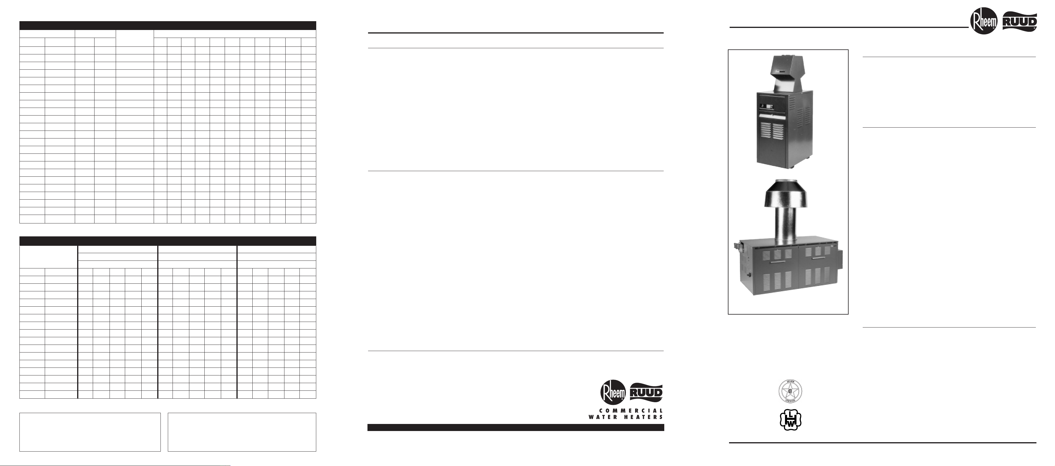
Gas Hot Water Supply Heaters
Available in Indoor and Outdoor Models
136,000 thru 1,826,000 BTU/Hr.
Rheem-Ruud hot water supply heaters are designed to provide hot water service to a variety of commercial applications
when used in conjunction with an appropriately sized storage
tank. These models are particularly suited for applications that
require high inputs and large volumes of stored hot water.
Construction Features:
• Reliable heat exchanger
Design – The all copper
heat exchanger is a single bank, straight-through
design with a floating
return header immune to
thermal shock.
• Energy saving pump
control – The energy
saving pump control is an
electric device that allows
the operator to set the
desired time for the pump
to run after the water
heater shuts off. With the
energy saving pump
control the water heater
pump is programmed to
continue running for an
optimum period of time
in order to absorb the
residual heat from the
combustion chamber and
Indoor Models
Indoor and Outdoor
Models
Pump Mounted Models
Available
5 Year Limited Warranty
use it in the system.
Certifications and Ratings:
•
Efficiency – These models have been tested according to ANSI
test procedures, and meet or exceed the 82% thermal efficiency
requirement of current ASHRAE standards (Part of the Federally
mandated Energy Policy Act (EPact)). Also exceeds energy
efficiency codes of all states.
•
Safety and Construction – These products are design certified
by the CSA: a) As a Hot Water Supply Water Heater equipped
with on/off controls for use in conjunction with a storage tank.
b) For operation at 180°F. c) To meet all safety and construction
requirements of ANSI Z21.10.3.c) For installation on combustible
flooring when used with a combustible floor base, and, or e) for
alcove installation. ASME construction is standard on all models.
Certified for a 160 PSI Maximum Working Pressure.
• Compact design –
The low water heater
mass design offers
substantial savings in
weight and cube over
most cast iron, steel tube
and storage-type water
heaters making it ideal
for rooftop installations
and in tight quarters.
• Minimal heat loss design
– Spark-to-pilot (IID)
system is standard on
all models.
• Glasslined cast iron
headers –
To handle aggressive
water conditions. (Models
GBBP/GBB136 feature
bronze headers.)
Continued next page.
Page 2

OUTLET
INLET
REAR VIEW
B
L
14
1
/
2
10
1
/2
3
1
/4
15
3
/8
7
1
/4
1
1
/4
38
1
/
2
24
1
/4
FRONT VIEW
4
7
/8
4
3
/4
C
K
A
G
GAS
E
LEC.
CONN.
INDOOR OUTDOOR
UP FRONT
CONTROLS
2
2
OPTIONAL
ON INDOOR
COMBUSTIBLE
FLOOR SHIELD
OUTLET INLET
OUTDOORINDOOR
B
C
28
1
/4
44
1
/8
29
1
/2
11
1
/8
2
1
/4
6
14
3
/4
17
G
GAS
2
K
A
18
14
1
/2
2
1
/4
5
L
A
2
COMBUSTIBLE
FLOOR SHIELD
ELEC
CONN
OPTIONAL
ON INDOOR
K
68-3/4
INDOOR
DRAFT
(B)
STACKLESS
OUTDOOR TOP
PUMP COVER
(OPTIONAL
OUTDOOR
MODELS ONLY)
21-1/4
ELECTRIC
CONNECTION
13-1/4
GAS
CONNECTION
3/4 NPT
GAS
CONNECTION
1-1/2 NPT
WATER
CONNECTION
J
(C)
26-1/2
26-1/2
8-1/2
3-7/8
A
10-1/4
9-7/8
PUMP
(OPTIONAL)
OUTLET
INLET
A
K
B
A
2
18
14
1
/2
11/8
51/8
21/2
273/4
21/2
463/4
321/2
111/4
113/4
111/8
C
J
14
6
G
GAS
5
/8
5
18
OUTDOOR
OPTIONAL
ON INDOOR
OUTLET INLET
COMBUSTIBLE
FLOOR SHIELD
ELEC
CONN
INDOOR
Three Important Reasons to Choose Hot Water Supply Heaters
from Rheem-Ruud Commercial Water Heaters
Reliability
Like all of our water heating products,
•
Rheem-Ruud hot water supply
heaters are crafted to exacting
standards. Each detail of design,
engineering and construction must
meet our criteria for performance
and durability.
• The heat exchanger (1), for example,
is constructed of 100% copper. High
Velocity hydraulics (2) virtually eliminates problems of scaling and corrosion within its waterways. The cast
iron headers (3) are glass-lined to
assure that the entire heat exchanger
assembly is resistant to corrosion.
• Every Rheem-Ruud hot water supply
heater features titanium stainless
steel burners (4). They operate
quietly, will not clog or corrode, and
have far greater temperature
resistance than cast iron. The
controls (5) are factory adjusted
and completely enclosed for reliable,
automatic operation.
• The outer jacket (6) is galvanized
and powder coated for lasting
aesthetics.
Efficiency
• Today’s demands for volume hot
water must be met economically, so
we’ve attempted to use every fuel
saving technique conceivable. The
resulting 82% efficiency will save you
money in fuel costs for years to come.
• The integral finned copper tubing
(7) in the heat exchanger provides
nine times more heat transfer area
than smooth tubing. Efficiency is
boosted even further by V-baffles (8),
which redirect the heat across the
finned tubing. The insulated
combustion chamber (9) features
corner sealed and interlocking
refractory panels to minimize
chamber radiation losses.
• Economy is further enhanced with a
special energy saving pump control.
This automatic control continues
pump operation until all usable heat
has been absorbed from the combustion chamber and stored in the tank.
• Access to water heater for inspection
is simple. All Rheem-Ruud hot water
supply heaters feature a heat
exchanger inspection panel (10)
and a removable door to access the
slide out burner drawer (11).
cast-iron glass-
3
lined headers,
easily removable
corner sealed
9
and interlocked
combustion
chamber
Flexibility
• You’ll find that Rheem-Ruud hot
water supply heaters are perfectly
suited for many commercial, industrial and special application needs
requiring economical, reliable supplies of hot water. The optional factory supplied pump is designed to
handle nearly all water conditions
• Our standard sized water heaters –
nine models ranging from 136,000 to
825,000 BTU – are designed for hot
water supply in commercial applications. Each model is available for
indoor and outdoor installation. The
outdoor models feature a special
draft system which is wind, rain and
debris-proof.
galvanized and powder
6
coated jacket
8
4
high velocity
2
hydraulics
1
high efficiency
“V” baffles
precision titanium
stainless steel
burners
• Our large sized water heaters –
seven indoor and seven outdoor
models ranging from 926,000 to
1,825,600 BTU – meet the heavier
demand of larger multi-family housing and commercial applications.
They are ideal for use as summer
replacement water heaters, eliminating the need to fire large central
heating water heaters merely to
supply domestic hot water.
• All of these Rheem-Ruud hot water
supply heaters are compact and
convenient; they save space, fuel
and installation cost.
100% copper
heat exchanger
heat
10
exchanger
inspection
panel
totally
enclosed
5
automatic
controls
removable door
11
for access to
slide out
burner drawer
7
integral
finned
copper
tubing
Example System
INDOOR
MODELS
OUTDOOR
MODELS
••OPTIONAL
I
NTEGRAL PUMP
HOT WATER SUPPLY
RECIRCULATION
ON MODELS 512 - 1826
THERMOMETER
COLD WATER
RECIRCULATION
PUMP
(BY OTHERS)
TANKSTAT
LOCATION
A
DRAIN
OPENING
PUMP AND BALL VALVE LOCATION ON
MODELS 136 THRU 399
•• OPTIONAL ON MODELS
512 THRU 1826 WITHOUT INTEGRAL PUMP
NOTES:
1. PLUMB SWING CHECK VALVE IN GRAVITY CLOSED
POSITION.
2. MINIMUM PIPE EQUAL TO WATER HEATER INLET/OUTLET
CONNECTION SIZE BETWEEN WATER HEATER AND TANK(S)
3. PIPE ALL RELIEF VALVES TO DRAIN, OR AS LOCAL CODES
REQUIRE
MINIMUM PIPE SIZE
Model Dimension
Size A
136 1-1/4"
186-399 1-1/2"
512-825 2"
926-1826 2-1/2"
WATER HEATER
SHOWN REPRESENTS
VARIOUS MODELS.
BECAUSE MODELS
WILL VARY IN DRAFT
HOOD DESIGN AND
SIZE, SEE SPECIFIC
WATER HEATER
INFORMATION FOR
DETAILS.
KEY
PRESSURE
RELIEF VALVE
UNION
AL L VALV E
B
GA T E VA LV E
CHE CK VA LVE
PUM P
Guaranteed 80% draw without temperature drop,
using Rheem-Ruud water heaters, tanks, sizing tables and hook-up data.
JACKET INSULATED STORAGE TANKS BY RHEEM-RUUD (All dimensions shown in inches)
Model Gallons Height Diameter Hot Outlet Line Connection Standard ASME
Capacity Overall Connection Circulating Relief Valve Weight (Lbs.)
ST80(A) 80 58-5/16 24-7/16
221
ST120(A) 115 59-1/4 28-1/4 221260 340
ST175(A) 175 67-1/4 32-1/4 2-1/2 2-1/2 1 600 600
ST200A 200 77-1/4 32 2 2-1/2 1 N/A 500
ST260A 257 95-1/2 34 231-1/4 N/A 1108
ST320A 318 84-1/2 40 231-1/4 N/A 1290
ST430A 432 84-1/2 46 231-1/4 N/A 1626
ST500A 504 94-1/2 46 231-1/4 N/A 1765
ST750A 752 107-1/2 54 231-1/4 N/A 2330
ST950A 940 131-1/2 54 231-1/4 N/A 3010
These storage tanks meet standby loss requirements of ASHRAE 90.1b-1992.
(A) ASME code constructed tanks available as an option.
Consult specification sheets RR102C-3 and RR102C-3LT for complete details.
Connections Approx. Shipping
220 260
SPECIFICATIONS AND DIMENSIONS
MODEL NUMBER STYLE MBTUH NATURAL GAS (X 1000) DIMENSIONS (INCHES) SHIPPING WEIGHT††
Ref. With- Height Jacket Gas Flue
o out With In- Out- (indoor) (outdoor) Width Overall Height Conn. Dia.
t
wg. Pump Pump door door Input Output Input Output AB CGJKLMN(Indoor) (Outdoor)
D
GBB136* GBBP136* ••136.0 112.0 136.0 112.0 14
1
GBC186** GBCP186** ••181.0 148.0 181.0 148.0 18
GBC264** GBCP264** ••264.0 216.0 264.0 216.0 22
2
BC331** GBCP331** ••334.0 274.0 334.0 274.0 25
G
BC399** GBCP399** ••399.0 327.0 399.0 327.0 29
G
GBC512 GBCP512 ••511.5 419.4 511.5 419.4 32
BC627 GBCP627 ••627.0 514.1 627.0 514.1 37
G
3
BC726 GBCP726 ••726.0 595.4 726.0 595.4 41
G
GBC825 GBCP825 ••825.0 676.5 825.0 676.5 45
GBC926 GBCP926 –• – –926.0 759.3 52
BC962 GBCP962 •–961.7 788.6 ––52
G
GBC1083 GBCP1083 –• – –1083.0 888.1 59
GBC1125 GBCP1125 •–1124.7 922.2 ––59
BC1178 GBCP1178 –• – –1178.0 966.0 63
G
BC1223 GBCP1223 •–1222.5 1002.4 ––63
G
GBC1287 GBCP1287 –• – –1287.0 1055.3 68
4
GBC1337 GBCP1337 •–1336.6 1096.0 ––68
BC1413 GBCP1413 –• – –1413.0 1158.7 74
G
GBC1467 GBCP1467 •–1467.0 1202.9 ––74
GBC1570 GBCP1570 –• – –1570.0 1287.4 81
BC1630 GBCP1630 •–1630.0 1336.5 ––81
G
BC1758 GBCP1758 –• – –1758.0 1441.6 89
G
GBC1826 GBCP1826 •–1825.6 1496.9 ––89
* Equipped with bronze headers, all other models have glasslined cast iron headers. GBC – cast iron headers. GBB – bronze headers.
†† Subtract 55 lbs. when ordering GBC models.
** Low NOx models add “N” after model number. Outdoor models add “-O” after model number.
Indicate Natural or LP when ordering.
MBTUH PROPANE GAS†
Model
Size Multiplier
136-399 Same as natural gas
512-825 .94
926-1826 .92 Indoor
.955 Outdoor (input)
.92 Outdoor (output)
† Multiplier x Nat. MBTUH = Pro. MBTUH
DRAWING 1 DRAWING 2
DRAWING 3 DRAWING 4
MIN. CLEARANCES TO COMBUSTIBLE SURF.
Model Left Right
Size Rear Side Side Indoor Outdoor
136 12" 12" 6" 42" Unobstr.
186-399 12" 12" 12" 39" Unobstr.
512-825 12" 18" 6" 36" Unobstr.
926-1826 24" 24" 24" 24" Unobstr.
For servicing provide 24" minimum unobstructed clearance
in front of unit.
1
5.0 30
⁄4 4
1
⁄4 40.0 38
3
⁄8 40.0 38
3
0.0 38
⁄4 4
1
0.0 38
⁄4 4
3
⁄4 57.0 33 1–10 253⁄8 –– 510 535
1
7.0 33 1–12 29
⁄2 5
5
7.0 33 1–12 34
⁄8 5
3
⁄4 57.0 33 1–14 381⁄2 –– 660 720
3
⁄8 ––1–––––– 790
3
8
⁄8 6
1
⁄4 ––1–––––– 850
1
⁄4 741⁄2 331⁄2 1 255⁄8 16 32 –– 800 –
5
⁄8 –
5
4
⁄8 7
5
⁄8 ––1
5
⁄8 761⁄2 331⁄2 11⁄4 235⁄8 18 36 –– 930 –
7
⁄8 –
7
⁄8 761⁄2 331⁄2 11⁄4 235⁄8 18 36 –– 1000 –
1
⁄8 ––1
1
9
⁄8 7
3
⁄8 –
3
⁄8 811⁄2 361⁄2 11⁄4 235⁄8 20 40 –– 1090 –
1⁄81
⁄2 –
3
⁄4 121⁄16 6– –– 191 200
3
⁄4 111⁄8 7––– 214 220
3
3
0
⁄4 1
⁄4 8
3
1
2
⁄4 1
⁄2 9
3
1
3
⁄4 3
⁄2 1
–1––––– – 910
1
1
3
⁄2 3
⁄2 1
–1
1
1
6
⁄2 3
⁄2 11⁄4 2
–1
Top
18 14 28 –– 760 –
5
23
⁄8 1
1
⁄4 ––––– – 975
1
⁄4 –
1
⁄4 ––––– – 1120
5
3
⁄8 1
1
⁄4 –
1
69
6 32 –– 860 –
–– –– – 1065
8 36 –– 1040 –
–– –– – 1150
Model
Size With Pump
136-399 3.7 amps @ 120V (1/8 hp pump)
331-399 3.6 amps @ 120V (1/6 hp pump)
512-1826 7.2 amps @ 120V (1/2 hp pump)
1
0
⁄4 1
⁄4 31⁄2 1
––– 234 240
––– 253 260
1
– 520 545
⁄2 –
1
– 630 685
⁄4 –
ELECTRICAL RATINGS
95 195
 Loading...