

Page 1
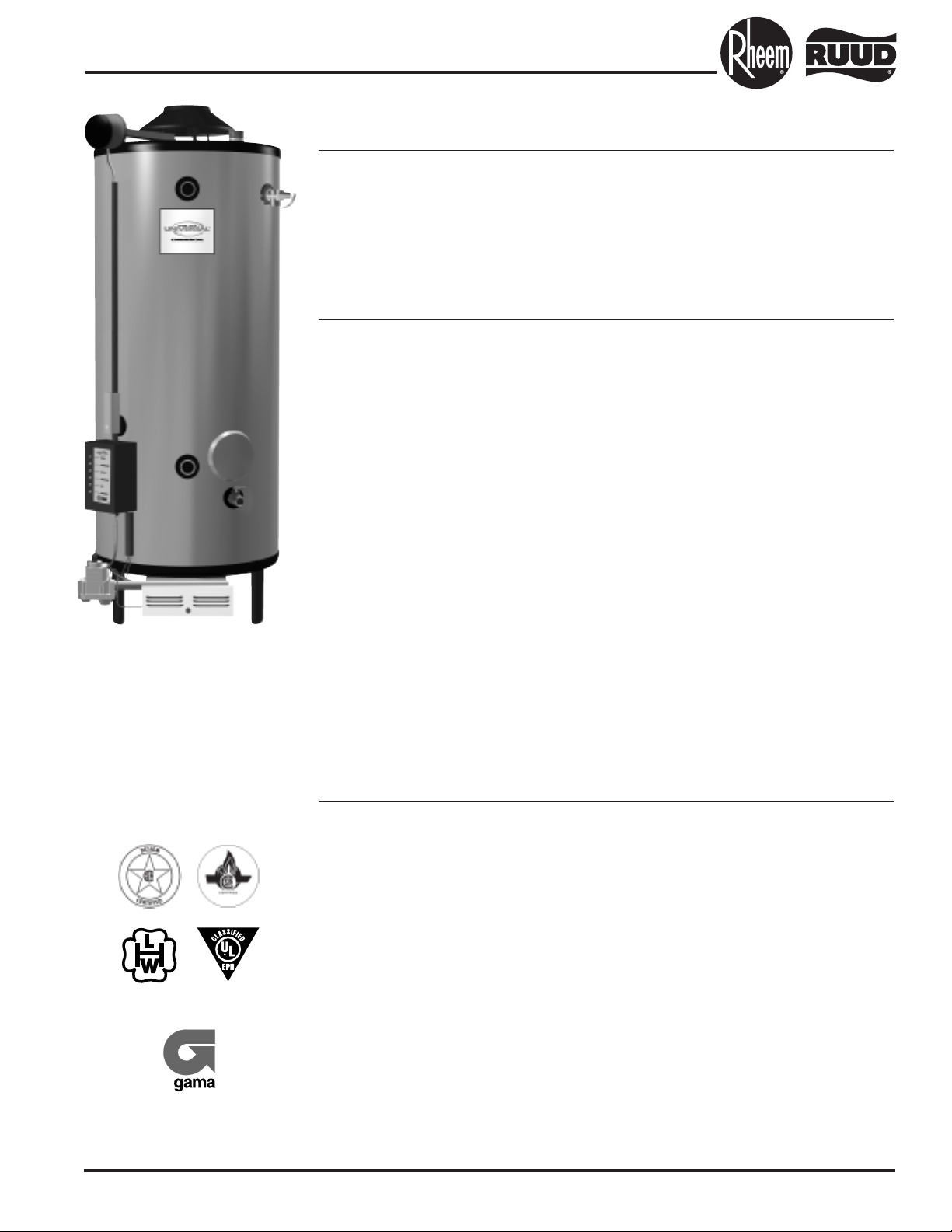
Universal Gas Commercial Water Heaters
Available in Sizes Ranging From 35 - 100 Gallon Tank-Type Models
98,000 BTU/Hr. thru 400,000 BTU/Hr.
Universal Gas Commercial Water Heaters are specifically designed to
minimize the difficulty of replacing failed water heaters and are versatile for
new installations. These products are designed for applications requiring
large quantities of hot water.
Construction Features:
Small Jacket
Diameters
Short
Floor-to-Vent
Heights
Multiple
Water Connection
Options
• Universal tank design –
maximizes installation adaptability
by offering models with Top, Front
Side and Rear Side Inlet/Outlet
water connections.
• Universal space saver design –
short heights and small jacket
diameters result in greater
installation flexibility.
• Patented multi-flue tank design –
proprietary steel formulation,
patented multi-flue design, and
two coats of high temperature
porcelain enamel to maximize
corrosion resistance result in a
superior heat exchanger design.
• Low profile automatic flue
damper –
low profile design minimizes overall product height. New heavy duty
vent hood supports are designed
to withstand rigors of installation.
• Spark-To-Pilot ignition system –
standard on all models. Provides
reliable and energy saving ignition
sequencing by igniting the pilot
only when the thermostat calls for
heat.
™
• System Sentinel
LED
diagnostic system –
our exclusive diagnostic system,
with glowing LED lights, verifies
system operation sequence by
sequence.
• Full port, full flow brass drain
valve
Certifications and Ratings:
• Efficiency – these models have been tested according to ANSI test
procedures, and meet or exceed the thermal efficiency and standby loss
requirements of current ASHRAE standard (Part of the Federally
mandated Energy Policy Act (EPact)). Also exceeds energy efficiency
codes of all states including California Energy Commission (CEC).
(On Selected
Models)
(With Optional
Leg Kit)
• Safety and construction – these products are design certified by the
CSA: a) For operation at 180°F. b) To meet all safety and construction
requirements of ANSI Z21.10.3. c) As an automatic storage or instantaneous water heater. d) As an automatic circulating tank water heater.
e) For operation on combustible floors and in alcove installations.
All models are North Carolina Code compliant.
CERTIFIED FOR A 150 PSI MAXIMUM WORKING PRESSURE
(160 PSI FOR ASME MODELS).
• Optional constructions – ASME construction is available on designated
models. UL Sanitation (NSF5) compliant models are available when
equipped with optional leg kit. (Part No. AE35450)
Continued next page.
Page 2
Universal Gas continued.
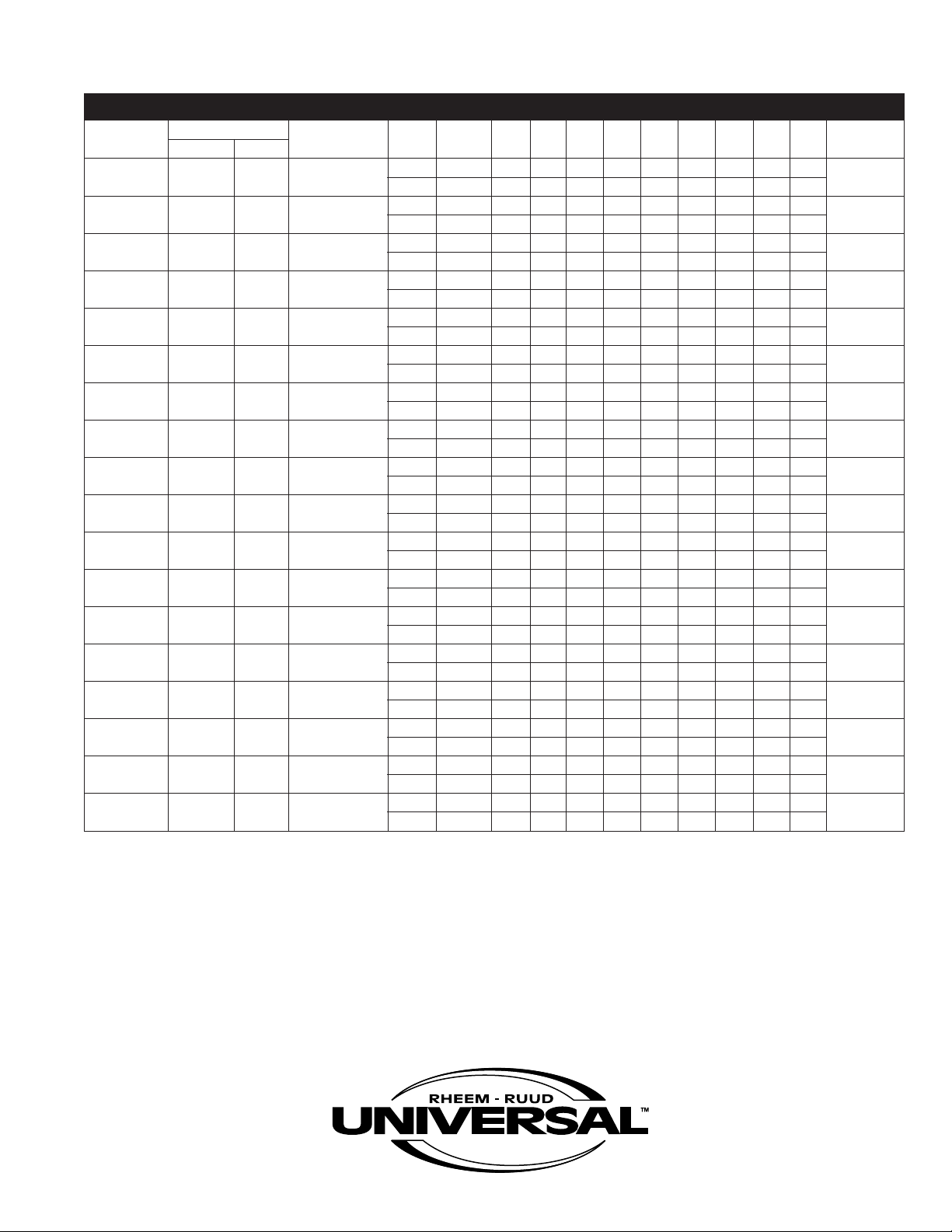
MAXIMUM DELIVERY In U.S. Gallons and Liters. (Includes useable storage and recovery for indicated times.)
MODEL TANK CAPACITY INPUT BTU/HR. TEMP. 5 10 15 20 30 45 60 120 180 Min. to Rec.
NUMBER GALLONS LITERS NAT. & L.P. RISE UNITS Min. Min. Min. Min. Min. Min. Min. Min. Min. Contents
G50-98 50 189 98,000 100°F GAL 43 51 59 67 83 106 130 225 320 32
37.7°C LTR. 162 192 222 252 312 402 492 852 1212
G75-125 75 284 125,000 100°F GAL. 63 73 83 93 113 143 174 295 416 37
7.7°C LTR. 237 275 313 352 428 543 658 1116 1575
3
G82-156 82 310 156,000 100°F GAL. 70 83 95 108 133 171 209 360 511 33
7.7°C LTR. 265 313 360 408 504 647 790 1363 1935
3
G76-180 76 288 180,000 100°F GAL. 68 82 97 111 140 184 228 402 577 26
37.7°C LTR. 256 311 367 422 532 697 862 1523 2183
G37-200 35 132 199,900 100°F GAL. 41 56 72 88 119 167 214 403 562 11
37.7°C LTR. 155 212 273 333 451 633 811 1527 2130
G76-200 76 288 199,900 100°F GAL. 69 86 102 118 150 199 247 441 635 24
7.7°C LTR. 263 324 385 446 568 752 935 1669 2403
3
G91-200 91 344 199,900 100°F GAL. 80 96 112 128 161 209 258 451 645 28
7.7°C LTR. 302 363 425 486 608 791 975 1709 2442
3
G100-200(A) 100 379 199,900 100°F GAL. 86 102 118 135 167 215 264 458 652 31
7.7°C LTR. 326 387 448 510 632 815 999 1732 2466
3
G72-250(A) 72 273 250,000 100°F GAL. 71 91 111 131 172 232 293 535 778 18
37.7°C LTR. 267 344 420 497 650 879 1108 2026 2944
G100-250(A) 100 379 250,000 100°F GAL. 90 110 131 151 191 252 312 555 797 25
37.7°C LTR. 341 418 494 571 724 953 1183 2100 3018
G100-270(A) 100 379 270,000 100°F GAL. 92 114 135 157 201 266 332 594 855 23
37.7°C LTR. 348 430 513 595 761 1008 1256 2247 3238
G72-300(A) 72 273 300,000 100°F GAL. 75 99 123 147 196 269 341 632 923 15
37.7°C LTR. 283 374 466 558 741 1017 1292 2393 3494
G85-300(A) 85 344 300,000 100°F GAL. 83 108 132 157 205 278 350 641 932 17
37.7°C LTR. 317 409 501 593 777 1052 1328 2430 3533
G100-310(A) 100 379 310,000 100°F GAL. 95 120 145 170 220 295 371 671 972 20
37.7°C LTR. 360 455 549 644 834 1118 1403 2541 3679
G65-360(A) 65 246 360,000 100°F GAL. 75 104 133 162 220 307 395 744 1093 11
37.7°C LTR. 282 392 503 613 833 1163 1494 2815 4136
G65-400(A) 65 246 399,900 100°F GAL. 78 110 142 175 239 336 433 821 1209 10
37.7°C LTR. 295 417 539 662 906 1273 1640 3108 4576
G85-400(A) 85 322 399,900 100°F GAL. 92 124 156 189 253 350 447 835 1223 13
37.7°C LTR. 348 470 592 715 959 1326 1693 3161 4629
G100-400(A) 100 379 399,900 100°F GAL. 102 135 167 199 264 361 458 846 1233 15
37.7°C LTR. 387 510 632 754 999 1366 1733 3201 4669
Page 3

Universal Gas continued.
RECOVERY CAPACITIES Recovery in U.S. Gallons/Hr. (GPH) and Liters/Hr. (LPH) at Various Temperature Rises.
MODEL INPUT BTU/HR. THERMAL 40°F 50°F 60°F 70°F 80°F 90°F 100°F 110°F 120°F 130°F 140°F
NUMBER NATURAL & L.P. EFFICIENCY UNITS
G50-98 98,000 80% GPH 238 190 158 136 119 106 95 86 79 73 68
LPH 899 719 600 514 450 400 360 327 300 277 257
G75-125 125,000 80% GPH 303 242 202 173 152 135 121 110 101 93 87
PH 1147 918 765 655 574 510 459 417 382 353 328
L
G82-156 156,000 80% GPH 378 303 252 216 189 168 151 138 126 116 108
PH 1432 1145 954 818 716 636 573 521 477 440 409
L
G76-180 180,000 80% GPH 436 349 291 249 218 194 175 159 145 134 125
PH 1652 1321 1101 944 826 734 661 601 551 508 472
L
G37-200 199,900 80% GPH 485 388 323 277 242 215 194 176 162 149 138
LPH 1834 1468 1223 1048 917 815 734 667 611 564 524
G76-200 199,900 80% GPH 485 388 323 277 242 215 194 176 162 149 138
LPH 1834 1468 1223 1048 917 815 734 667 611 564 524
G91-200 199,900 80% GPH 485 388 323 277 242 215 194 176 162 149 138
LPH 1834 1468 1223 1048 917 815 734 667 611 564 524
G100-200(A) 199,900 80% GPH 485 388 323 277 242 215 194 176 162 149 138
LPH 1834 1468 1223 1048 917 815 734 667 611 564 524
G72-250(A) 250,000 80% GPH 606 485 404 346 303 269 242 220 202 186 173
LPH 2294 1835 1529 1311 1147 1020 918 834 765 706 655
G100-250(A) 250,000 80% GPH 606 485 404 346 303 269 242 220 202 186 173
LPH 2294 1835 1529 1311 1147 1020 918 834 765 706 655
G100-270(A) 270,000 80% GPH 655 524 436 374 327 291 262 238 218 201 187
LPH 2478 1982 1652 1416 1239 1101 991 901 826 762 708
G72-300(A) 300,000 80% GPH 727 582 485 416 364 323 291 264 242 224 208
LPH 2753 2202 1835 1573 1376 1224 1101 1001 918 847 787
G85-300(A) 300,000 80% GPH 727 582 485 416 364 323 291 264 242 224 208
LPH 2753 2202 1835 1573 1376 1224 1101 1001 918 847 787
G100-310(A) 310,000 80% GPH 752 601 501 429 376 334 301 273 251 231 215
LPH 2845 2276 1896 1626 1422 1264 1138 1034 948 875 813
G65-360(A) 360,000 80% GPH 873 698 582 499 436 388 349 317 291 269 249
LPH 3304 2643 2202 1888 1652 1468 1321 1201 1101 1016 944
G65-400(A) 399,900 80% GPH 969 776 646 554 485 431 388 353 323 298 277
LPH 3670 2936 2446 2097 1835 1631 1468 1334 1223 1129 1048
G85-400(A) 399,900 80% GPH 969 776 646 554 485 431 388 353 323 298 277
LPH 3670 2936 2446 2097 1835 1631 1468 1334 1223 1129 1048
G100-400(A) 399,900 80% GPH 969 776 646 554 485 431 388 353 323 298 277
LPH 3670 2936 2446 2097 1835 1631 1468 1334 1223 1129 1048
Recovery ratings are based on thermal efficiencies obtained in a CSA certified laboratory.
(A) indicates available ASME model.
22°C 28°C 33°C 39°C 45°C 50°C 56°C 61°C 67°C 72°C 78°C
Page 4

Universal Gas continued.
DIMENSIONAL INFORMATION All Dimensions Shown in English and Metric.
WATER CONNECTIONS APPROXIMATE
ODEL TOP FRONT REAR
M
UMBER UNITS
N
ABCDEFGHI
N/OUT SIDE SIDE STD. ASME
G50-98 inches 62-3/4 57-1/8 22-1/2 22-5/8 5 50-1/2 1/2 15 1 1-1/2 1-1/2 270 lbs. N/A
mm 1594 1451 667 575 127 1283 13 381 25 38 38 122 kgs. N/A
G75-125 inches 65-1/2 61 26-1/4 25 5 56 3/4 20 1-1/2 1-1/2 1-1/2 480 lbs. N/A
m 1664 1549 667 635 127 1422 19 508 38 38 38 217 kgs. N/A
m
G82-156 inches 68-13/16 64 26-1/4 25 6 58-5/8 3/4 20 1-1/2 1-1/2 1-1/2 490 lbs. N/A
m 1748 1626 667 635 152 1489 19 508 38 38 38 222 kgs. N/A
m
G76-180 inches 68-13/16 64 26-1/4 25 6 58-5/8 3/4 20 1-1/2 1-1/2 1-1/2 540 lbs. N/A
m 1748 1626 667 635 152 1489 19 508 38 38 38 245 kgs. N/A
m
37-200 inches 49-1/4 43-3/8 26-1/4 25 6 37-5/8 3/4 20 1-1/2 1-1/2 1-1/2 405 lbs. N/A
G
m 1251 1102 667 635 152 956 19 508 38 38 38 184 kgs. N/A
m
G76-200 inches 68-13/16 64 26-1/4 25 6 58-5/8 3/4 20 1-1/2 1-1/2 1-1/2 540 lbs. N/A
m 1748 1626 667 635 152 1489 19 508 38 38 38 245 kgs. N/A
m
G91-200 inches 76-5/16 71-13/16 26-1/4 30-5/8 6 66-3/8 3/4 20 1-1/2 1-1/2 1-1/2 600 lbs. N/A
mm 1938 1824 667 778 152 1686 19 508 38 38 38 272 kgs. N/A
G100-200(A) inches 73-1/16 66-1/8 30-1/4 23-1/4 6 57-1/2 3/4 23 1-1/2 22780 lbs. 835 lbs.
mm 1856 1680 768 591 152 1460 19 584 38 51 51 353 kgs. 378 kgs.
G72-250(A) inches 71-1/16 64-1/2 26-1/4 25 6 58-5/8 3/4 20 1-1/2 1-1/2 1-1/2 590 lbs. 630 lbs.
mm 1805 1638 667 635 152 1489 19 508 38 38 38 267 kgs. 285 kgs.
G100-250(A) inches 73-1/4 66-1/8 30-1/4 23-1/4 8 57-1/2 3/4 23 1-1/2 22795 lbs. 835 lbs.
mm 1861 1680 768 591 203 1460 19 584 38 51 51 360 kgs. 378 kgs.
G100-270(A) inches 73-7/8 66-1/8 30-1/4 23-1/4 8 57-1/2 3/4 23 1-1/2 22805 lbs. 845 lbs.
mm 1876 1680 768 591 203 1460 19 584 38 51 51 365 kgs. 383 kgs.
G72-300(A) inches 71 64-1/8 26-1/4 25 8 58-5/8 3/4 20 1-1/2 1-1/2 1-1/2 590 lbs. 630 lbs.
mm 1803 1629 667 635 203 1489 19 508 38 38 38 267 kgs. 285 kgs.
G85-300(A) inches 78-7/16 72-5/16 26-1/4 30-5/8 8 66-3/8 3/4 20 1-1/2 1-1/2 1-1/2 640 lbs. 680 lbs.
mm 1992 1837 667 778 203 1686 19 508 38 38 38 290 kgs. 308 kgs.
G100-310(A) inches 75 68-1/2 30-1/4 32-1/4 7 61-3/4 3/4 23 1-1/2 22770 lbs. 810 lbs.
mm 1905 1740 768 819 178 1568 19 584 38 51 51 349 kgs. 367 kgs.
G65-360(A) inches 70-11/16 64-1/2 26-1/4 25 8 58-5/8 3/4 N/A N/A 1-1/2 1-1/2 640 lbs. 680 lbs.
mm 1795 1638 667 635 203 1489 19 N/A N/A 38 38 290 kgs. 308 kgs.
G65-400(A) inches 70-11/16 64-1/2 26-1/4 25 8 58-5/8 3/4 N/A N/A 1-1/2 1-1/2 640 lbs. 680 lbs.
mm 1795 1638 667 635 203 1489 19 N/A N/A 38 38 290 kgs. 308 kgs.
G85-400(A) inches 78-13/16 72-5/16 26-1/4 30-5/8 10 66-3/8 3/4 20 1-1/2 1-1/2 1-1/2 640 lbs. 680 lbs.
mm 2002 1837 667 778 254 1686 19 508 38 38 38 290 kgs. 308 kgs.
G100-400(A) inches 76 68-1/2 30-1/4 32-1/4 8 61-3/4 1* 23 1-1/2 22770 lbs. 810 lbs.
mm 1930 1740 768 819 203 1568 25* 584 38 51 51 349 kgs. 367 kgs.
*3/4" (19mm) for L.P. Models. Increase Height 3-5/8" (92mm) for NSF Models.
All Models Require a 120V Power Source/0.3 amps. (A) Suffix Indicates ASME Tank Construction Available.
SHIPPING WEIGHT
Page 5

C
H
E
ABF
D
OUTLET
TOP
INLET
TOP
OUTLET
FRONT SIDE
OUTLET
REAR SIDE
SYSTEM
SENTINEL
T&P
INLET
FRONT SIDE
INLET
REAR SIDE
G
7"
(178mm)
Universal Gas continued.
DIMENSIONAL DIAGRAM
CLEARANCES TO COMBUSTIBLES
MODEL
UMBER UNITS SIDE REAR TOP
N
G50-98 inches
mm
G75-125 inches
m
m
82-156 inches
G
m
m
G76-180 inches
mm
G37-200 inches
mm
G76-200 inches
m
m
G91-200 inches
m
m
G100-200(A) inches
m
m
G72-250(A) inches
mm
G100-250(A) inches
mm
G100-270(A) inches
mm
G72-300(A) inches
mm
G85-300(A) inches
mm
G100-310(A) inches
mm
G65-360(A) inches
mm
G65-400(A) inches
mm
G85-400(A) inches
mm
G100-400(A) inches
mm
Allow a minimum of 18" (457mm)
front clearance for servicing.
2212
51 51 305
2212
1 51 305
5
2
1 51 305
5
2 12
2212
51 51 305
2212
51 51 305
2212
1 51 305
5
2212
1 51 305
5
2412
1 102 305
5
6612
152 152 305
2412
51 102 305
2412
51 102 305
6612
152 152 305
6612
152 152 305
6612
152 152 305
6612
152 152 305
6612
152 152 305
6612
152 152 305
6612
152 152 305
Page 6

Universal Gas continued.
Other Features:
• Insulation – sag and moisture proof fiberglass
insulation surrounds the storage tank to minimize heat loss. In addition, heavy mineral wool
insulation surrounds the combustion chamber.
• Anode rods – patented design utilizes multiple
magnesium rods to ensure long life and corrosion resistance.
• Temperature and pressure relief valve –
AGA/ASME rated and factory installed.
• Hand-hole cleanout – for removal of lime/sedi-
ment deposits.
• Gas control system – Fully adjustable
thermostat from 100°F to 180°F, 24 volt
combination gas valve includes main gas
pressure regulation, On-Off manual valve,
120/24 volt transformer, and high limit
temperature cut-out.
• Stainless steel burners – Precision burners
of raised port design are formed from high
chromium stainless steel. Entire burner
assembly is built like a drawer which slides
out easily for quick inspection and simple
maintenance.
• Manual reset high limit – all ASME models are
factory equipped with a manual reset high limit
to meet the code requirements of many states.
Recommended Specifications (for trade reference only)
Water heater(s) shall be UNIVERSAL model ________________, manufactured by RHEEM-RUUD,
having gas input of __________ Btu/hr. and a recovery rate of _____________ GPH at a 100°F temperature rise when tested and certified at ____________ thermal efficiency. Water heater(s) shall have
a storage capacity of _________ gallons. Water heater(s) shall have the CSA seal of certification and
supplied with a factory installed AGA/ASME rated temperature and pressure relief valve. Tank(s) shall
be furnished with a tube bundle having a double coating of high temperature porcelain enamel and furnished with magnesium anode rods rigidly supported. Water heater(s) shall meet or exceed the thermal
efficiency and standby loss requirements of ASHRAE. Tanks shall have a working pressure rating of
150 psi, and shall be completely factory assembled, including a pressure regulator properly adjusted for
operation on ___________ gas with stainless steel burners. Controls will be arranged for safety shutoff
in event of pilot failure. Water heater(s) with inputs less than 360,000 Btu/hr. shall have top, front and
rear side inlet/outlet water connections. Water heater(s) shall be covered by a three year limited
warranty against tank leaks.
• Add for ASME construction –
Water heater(s) shall be constructed in accordance with the requirements of the ASME Boiler and
Pressure Vessel Code, Section IV Part HLW.
Limited Warranty
This product features a three year limited warranty against tank leaks. Please refer to Commercial
Warranty Information brochure for complete warranty information.
In keeping with its policy of continuous progress and product improvement, Rheem-Ruud reserves the right to make changes without notice.
Rheem Water Heating • 101 Bell Road, Montgomery, Alabama 36117-4305 • www.rheem.com
Rheem Canada Ltd./Ltée,128 Barton Street West, Hamilton, Ontario L8N 3P3
P R I N T E D I N U . S . A 0 5 / 0 7 W P F O R M N O . R R 1 0 2 C -1 R e v . 1 7
 Loading...