

Page 1
C110 Dual Band 802.11ac Wall
Plate Cable Modem Access
Point
Quick Setup Guide
This Quick Setup Guide provides step-by-step instructions
on how to set up your Ruckus Wireless C110 Dual Band
802.11ac Wall Plate Cable Modem Access Point. After
completing the steps described in this Guide, you will be
able to access the C110 and begin providing wired and
wireless network access to users.
The C110 has many options:
• Includes DOCSIS (or EuroDOCSIS) 3.0 cable modem
• It can be mounted on a standard USA- or EU-style
single-gang wall outlet box.
• It has bottom cutouts for one or two bypass cables. The
mounting bracket has locating hooks to keep the
bypass cables aligned with the cutouts when attaching
the C110 to the mounting base.
• It can have a low-power (0.5W or less) customersupplied USB device plugged in.
NOTE: The C110 requires a minimum firmware revision
of SmartZone 3.4 or later to operate.
THIS GUIDE IN OTHER LANGUAGES
• 请从以下网站获得该指南的简体中文版
https://support.ruckuswireless.com
• Vous trouverez la version française de ce guide à
l'adresse suivante
• ガ イ ド ⽇本語版 https://support.ruckuswireless.com
で覧く だい
• 이 가이드의 한국어 버전은 웹 사이트
https://support.ruckuswireless.com) 에서 확인하시기 바랍니다
(
• Veja a versão em português (Brasil) deste guia em
https://support.ruckuswireless.com
• Puede ver la versión en español (América Latina) de
esta guía en
https://support.ruckuswireless.com
https://support.ruckuswireless.com
BEFORE YOU BEGIN
Before deploying Ruckus Wireless products, please check
for the latest software and the release documentation.
• User Guides and Release Notes are available at
http://support.ruckuswireless.com/documents
• Software Upgrades are available at
http://support.ruckuswireless.com/software
• Open Source information is available at
http://opensource.ruckuswireless.com
• Software License and Limited Warranty are available at
http://support.ruckuswireless.com/warranty
About Peripheral Devices
The C110 can supply power to USB devices through its
USB port on the bottom of the unit.
• The USB port is intended for low-power devices such
as BLE (Bluetooth low energy) beacons. The maximum
power that the USB port can supply is 0.5W.
PACKAGE CONTENTS
• C110 Cable Modem Access Point
• AC/DC power supply
• Mounting bracket
• Two 10mm M3x0.5 thread Torx flat head machine
screws
• Two 1” 6-32 thread Phillips pan head machine screws
• Two 4” long cable ties
• Product warranty statement
• Regulatory flyer
• Declaration of Conformity, if required
•This
Quick Setup Guide
CONFIGURING THE C110 (OPTIONAL)
Note: The C110 normally receives its latest AP and CM
firmware and initial configuration settings from the cable
modem termination system (CMTS) high speed data
services equipment when it powers up; if this is the case,
then skip the following steps and continue with
the Mounting Bracket to an Outlet Box.
If the C110 does not receive its latest firmware and initial
configuration settings from the CMTS equipment when the
AP powers up, then continue with these procedures:
•
Step 1: Collecting Tools and Setup Requirements
• Step 2: Connecting the Computer to the C110
• Step 3: Preparing Your Computer for C110 Setup
• Step 4: Logging Into the C110 Access Point
• Step 5: Customizing the Wireless Settings
Step 6: Attaching
STEP 1: COLLECTING TOOLS AND SETUP
REQUIREMENTS
• No. 2 Phillips screwdriver and T10 Torx driver for the
mounting bracket screws
• A standard USA- or EU-style single-gang wall outlet
box
• Coaxial cable for backhaul
• A computer with an Ethernet port, wireless card and a
web browser
• Cat 5e or better Ethernet cable (for initial software
configuration)
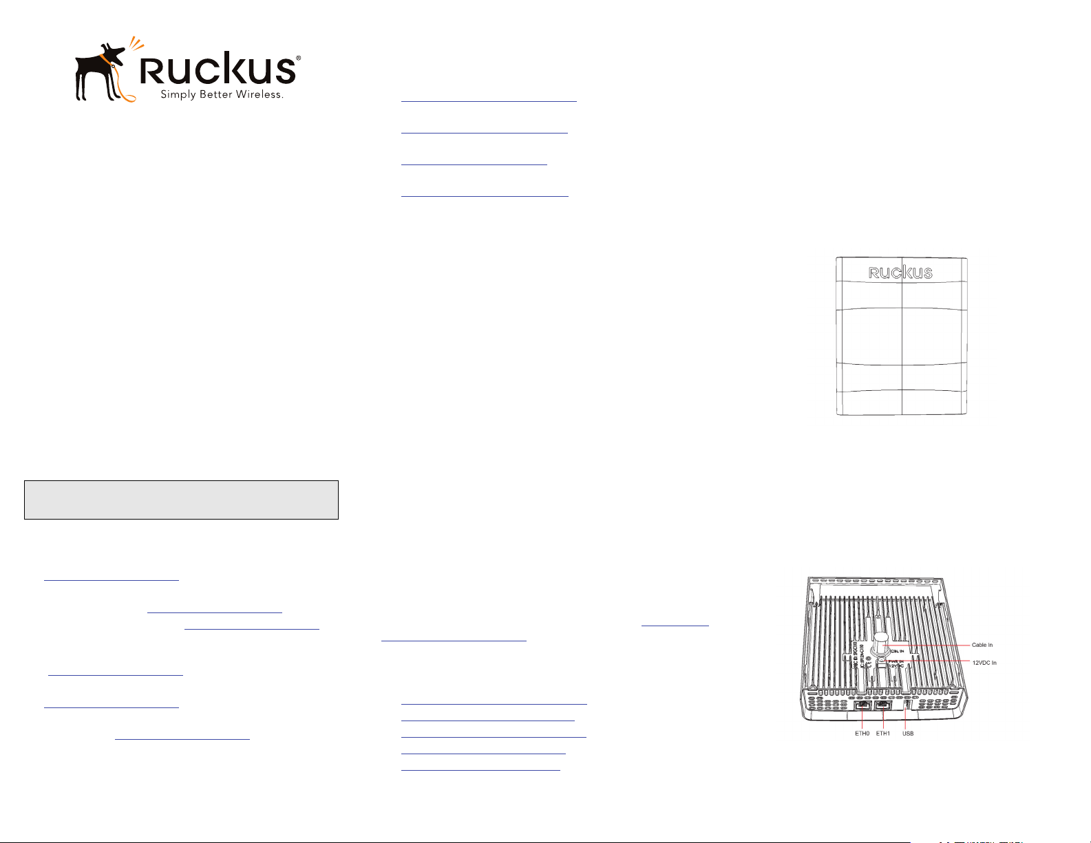
STEP 2: CONNECTING THE COMPUTER TO THE C110
Figure 1: Front view
1 After removing your C110 from its package, place it
next to your computer.
2 Using an Ethernet cable, connect your computer’s net-
work port to either of the Ethernet ports on the bottom
of the C110.
3 Using an AC adapter (included), connect the C110
12VDC port to a protected power source.
Figure 2: Rear and bottom view
Copyright © 2016 Ruckus Wireless, Inc. Page 1 of 4
Published June 2016, Part Number 800-71062-001 Rev A
Page 2

STEP 3: PREPARING YOUR COMPUTER FOR C110
SETUP
NOTE: The following procedures assume Windows 7
as the operating system. Procedures for other OS’s are
similar.
1 On your Windows 7 computer, configure your network
adapter from the Local Area Connection settings as follows:
• Start > Control Panel > Network and Sharing
Center > Change Adapter Settings
2 Edit the TCP/IPv4 address settings as follows:
• Local Area Connection > Properties > Internet
Protocol Version 4 (TCP/IPv4) > Properties
The Internet Protocol Version 4 (TCP/IPv4) Properties
dialog box appears.
IMPORTANT! Write down all of the currently active
settings so you can restore your computer to its
current configuration later, when this process is
complete.
3 Select Use the following IP address (if it is not already
selected) and then make the following entries:
• IP address: 192.168.0.22 (or any available address in
the 192.168.0.x network, except 192.168.0.1)
• Subnet mask: 255.255.255.0
• Default gateway: 192.168.0.1
Leave the DNS server fields empty.
4 Click OK to save your changes.
Your changes are put into effect immediately.
STEP 4: LOGGING INTO THE C110 ACCESS POINT
As specified in Step 3: Preparing Your Computer for C110 Setup, the C110 should be directly connected to your computer (through the Ethernet port on the bottom of the C110) and powered on, ready for setup.
1
On your computer, open a web browser window.
2 In the browser, type this URL to connect to the C110:
• https://192.168.0.1
3 Press <Enter> to initiate the connection. When a security
alert dialog box appears, click OK/Yes to proceed.
4 When the Ruckus Wireless Admin login page appears,
enter the following:
• Username: super
STEP 4A: OPERATING THE CABLE MODEM
Note: If the C110 CM is going to be managed by a CMTS, then skip this
section and continue with
Note: The CM and AP each have their own independent firmware load
that are each updated independently.
Continue with
Into the CM Web Interface via a Dynamic IP Address.
Logging Into the CM Web Interface via the Ethernet Port or Logging
Logging Into the CM Web Interface via the Ethernet Port
1 Complete
Step 3: Preparing Your Computer for C110 Setup.
2 On the administrative computer, open a web browser
window.
3 In the address or location bar, type the CM IP address,
for instance:
192.168.100.1
--OR-<DHCP-assigned CM IP address>
4 The CM web interface displays a login prompt.
5 Leave User Name blank.
6 In Password, type ADMIN.
7 Click Log In. The Connection Status page appears, indicat-
ing that you have successfully logged on to the CM web
interface.
Logging Into the CM Web Interface via a Dynamic IP Address
1 Connect the administrative computer to the same sub-
net as the C110.
2 On the administrative computer, start a web browser.
3 In the address bar, enter the IP address that is assigned
to the CM by the CMTS. The CM web interface displays
a login prompt.
4 Leave User Name blank.
5 In Password, type ADMIN.
6 Click Log In. The Connection Status page appears, indicat-
ing that you have successfully logged on to the CM web
interface.
Step 6: Attaching the Mounting Bracket to an Outlet Box.
Step 1: Collecting Tools and Setup Requirements through
STEP 5: CUSTOMIZING THE WIRELESS SETTINGS
Default C110 Access Point Settings (for your reference)
Network Names (SSIDs) Wireless1-Wireless8
(2.4GHz radio)
Wireless9-Wireless16
(5GHz radio)
Security (Encryption
method)
Default Management IP
Address
1 On the web interface menu, click Configuration > Radio
2.4G or Configuration > Radio 5G. The Configure > Wireless
> Common page appears.
2 Verify that the following options are active:
• Channel: SmartSelect.
• Country Code: If you are not located in the United
States of America, select your current country.
3 Click Update Settings if you made any changes.
4 Click any of the “Wireless #” (Wireless LAN Number)
tabs at the top of the page.
5 In Wireless Availability, click Enabled.
6 Delete the text in the SSID field, then type a name for
your network that will help your users identify the C110
access point in their wireless network connection applications.
7 Click Update Settings to save your changes.
8 Repeat Steps 4-7 for each Wireless # (Wireless LAN
Number) interface that you want to enable.
9 Click Logout to exit the Web interface.
Optional: In a default C110 configuration, the C110 uses
a DHCP-assigned IP address.
If you anticipate logging into the C110 regularly to
perform monitoring or maintenance once it is in place,
then you may want to consider switching from DHCP
and instead assigning a static IP address to the C110.
A On the menu, click Configuration > Internet.
B Click the Static IP option.
C Fill in the IP Address and Mask fields.
D Click Update Settings to save your changes.
10 When the Ruckus Wireless Admin login page reappears,
you can exit your browser.
Disabled for each wireless
interface
192.168.0.1
• Password: sp-admin
5 Click Login.
Copyright © 2016 Ruckus Wireless, Inc. Page 2 of 4
Published June 2016, Part Number 800-71062-001 Rev A
Page 3
11 Disconnect the C110 from the computer and from the
power source, and then restore your computer to its
original network connection configuration.
Continue with
Step 6: Attaching the Mounting Bracket to an Outlet Box.
STEP 6: ATTACHING THE MOUNTING BRACKET TO
AN OUTLET BOX
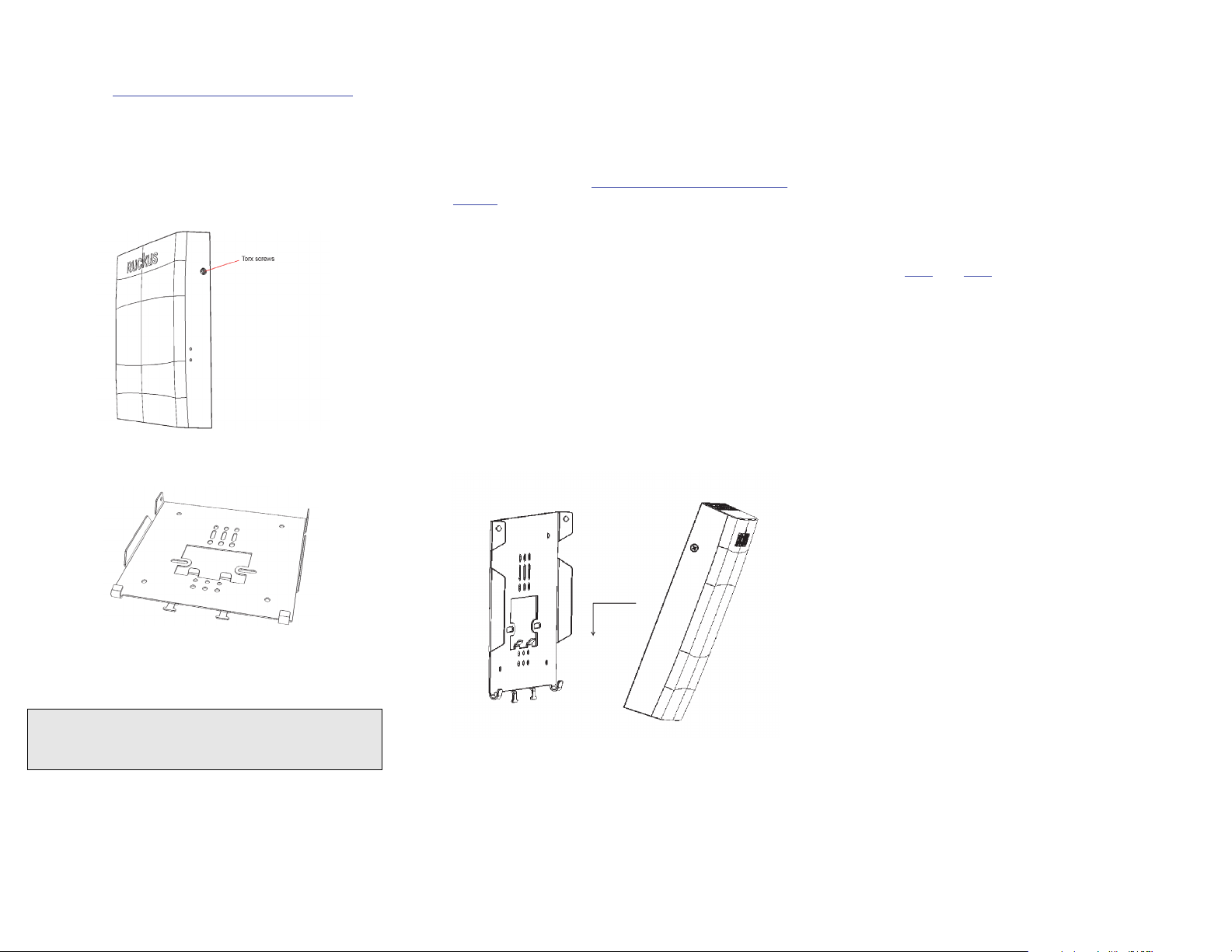
1 Using a T10 torx screwdriver, remove the two torx lock-
ing screws from the sides of the AP.
Figure 3: Remove the torx screws to detach the bracket from the AP
2 Remove the mounting bracket from the rear of the AP.
Figure 4: Mounting bracket
6 When you have extra bypass cables (up to two) that are
to bypass the C110, pull them through the wall outlet
box. Note: The bypass cables can be Ethernet, coax, or
any other type of cable, as required.
STEP 7: ATTACHING THE C110 TO THE MOUNTING BRACKET
1 Make sure that the mounting bracket is securely fas-
tened as described in
Outlet Box.
2 If you are installing a customer-supplied USB device
(such as a BLE beacon), then plug it securely into the
USB jack on the bottom of the C110.
3 Pull the uplink coaxial cable from your network through
the outlet box, and plug it into the back of the C110.
4 Connect the power adapter cable to the 12VDC in port
on the back of the C110.
5 The mounting bracket has two lower hooks that fit into
slots on the bottom of the C110. Rest the bottom of the
C110 on those hooks, and then tilt the C110 toward the
wall until it is up against the mounting bracket.
Note that any optional bypass cable(s) should slide
smoothly into the slots on the bottom of the C110.
Figure 5: Attaching the C110 to the Mounting Bracket
Step 6: Attaching the Mounting Bracket to an
STEP 8: TESTING THE C110 OPERATION
After a short pause to re-establish the Internet connection,
you can test the C110.
1 Using any wireless-enabled computer or mobile device,
search for and select the wireless network you previously configured.
2 If you can connect, open a browser and navigate to any
public Web site.
3 Using any wired computer or other device and an Ether-
net cable, plug into an Ethernet port on the bottom of
the C110.
4 Open a browser and navigate to any public Web site.
5 Repeat
on the bottom of the C110.
6 Verify that any connected USB devices are working cor-
rectly, if applicable.
Congratulations! Your C110 is active and ready for use.
Step 3 and Step 4 for the rest of the Ethernet ports
3 Use either the original wall outlet box screws or the fac-
tory-supplied 1” Phillips pan head machine screws to
attach the C110 mounting bracket to a single-gang wall
outlet box.
NOTE: The C110 mounting bracket has two hooks that
face UP. Make sure that the hooks are facing up when
attaching the mounting bracket to the wall outlet box.
4 Pull the coaxial cable for the C110 through the wall out-
let box.
5 Pull the power cable from the adapter through the wall
6 Use a T10 Torx driver to screw the factory-supplied Torx
flat head machine screws through the C110 screw holes
into the threaded inserts on the sides of the mounting
bracket.
outlet box.
Copyright © 2016 Ruckus Wireless, Inc. Page 3 of 4
Published June 2016, Part Number 800-71062-001 Rev A
Page 4

Copyright © 2016 Ruckus Wireless, Inc. Page 4 of 4
Published June 2016, Part Number 800-71062-001 Rev A
Page 5

Access Point
Getting Started Guide
This Getting Started Guide provides getting started
information for version 104.x and later Ruckus Wireless
base image access points (APs).
This document assumes familiarity with the Ruckus
ZoneFlex (ZF), ZoneDirector (ZD), SmartZone (SZ), and
FlexMaster (FM) product lines and the features of earlier
releases.
: This document covers Ruckus Wireless APs. For
NOTE
information about ZD and SZ controllers, as well as FM
managers, please refer to their respective user
documents.
: For Ruckus Wireless APs running version 104.x
NOTE
and later, please be advised that:
• The Ruckus Wireless AP may send a query to Ruckus
containing the AP’s serial number. The purpose is to
enable your AP to autonomously connect with a
wireless LAN controller operated by your choice of
cloud service provider. Ruckus may transmit back to
the AP the Fully Qualified Domain Name (FQDN) or IP
address of the controller that the AP will
subsequently attempt to join.
• Please be advised that this information may be
transferred and stored outside of your country of
residence where data protection standards may be
different.
CERTIFICATE CHANGES
Beginning in November 2016, the existing default SSL
device certificate on Ruckus APs will expire. Ruckus has
been rolling out replacement certificates on APs since
2015. Build 104 makes the new replacement certificate
the default SSL device certificate.
All APs shipped from Ruckus with release 104 and later
will have the new replacement certificates for SSL
authentication with SmartZone controllers.
Due to this change, APs with release 104 may not be
able to join some older versions of SZ software. To
address this limitation, the SZ has to be upgraded to
3.1.2 or later.
The certificate expiry will require all APs to have the new
replacement certificates loaded and made default to be
able to join SZ with certificate check beyond November
2016. If, after November 2016, the AP is not able to join
SZ, please contact Ruckus Support for assistance.
STANDALONE OR FLEXMASTER-MANAGED
OPERATION
Ruckus Wireless APs are shipped from the factory with a
single firmware image, referred to as the "base image."
APs with the base image can only operate in standalone
mode with or without a FlexMaster manager.
Controller-specific features (such as Smart Mesh
networking) are unavailable when the AP is running a
standalone AP base image.
Refer to the Ruckus Wireless Indoor Access Point User
Guide or the Ruckus Wireless Outdoor Access Point User
Guide for instruction on how to configure the AP for
standalone and/or FlexMaster-managed operation.
CONTROLLER MANAGEMENT
In addition to standalone and FlexMaster management,
ZoneFlex APs can also be managed by Ruckus Wireless
ZoneDirector or SmartZone controller platforms. When
the AP discovers one of these controllers on the network,
the AP downloads the associated controller-specific
image and replaces the base image with the
controller-compatible AP firmware.
"Island" SSID
Beginning with AP base image release 104.0, the
"island-xxxxxx" SSID that is broadcast when an AP
starts up in factory default state can be accessed using
the AP’s serial number as the PSK passphrase. This
change makes it easier to configure an AP that has
already been installed.
Ruckus Cloud Discovery
Ruckus Cloud Wi-Fi is WLAN Management-as-a-Service
that enables enterprises with limited IT resources to
easily set-up, monitor, and manage a high-performance
multi-site WLAN of any size, without compromising on
Wi-Fi performance.
Beginning with Release 104.0, all Ruckus 802.11ac APs
have the ability to discover and register with a Ruckus
Cloud controller (note that 802.11n APs do not have this
capability). 11ac APs with 104 image will use secure
HTTPS to query the AP Registrar to discover the
remote/cloud controller. If found, the AP will utilize
secure mechanisms (e.g., SSH port 22 and HTTPS port
11443) to communicate with the remote vSZ/Cloud
controller to connect, and download firmware.
The AP will probe the AP Registrar more often in the first
14 days after initial power-up, and after that, less
frequently. Once the AP finds a controller (ZD, SZ, or
Cloud), it will no longer look for the AP Registrar.
: If APs are intended for management by Ruckus
NOTE
Cloud controller, and you have any other Ruckus
controller on your local network, you must disable the
option to "Automatically approve all AP join requests"
from the controller UI before connecting the AP to the
network. If not, the AP will register with the local
controller first and will be unable to discover Ruckus
Cloud.
SmartZone AP Discovery Process
SmartZone controllers running version 2.5 and later
include an LWAPP2SCG utility for migrating Ruckus APs
to SmartZone control.
Ruckus APs running version 104.x and later can discover
SmartZone controllers without the need to enable the
LWAPP2SCG service on the controller and open ports
12223 and 21 on any firewalls or NAT devices between
the controller and the APs.
: Some older APs may not be able to discover an
NOTE
SZ controller using this discovery process. If you
encounter this issue, you have two options:
• First upgrade the AP to base image 104 or later.
• Enable LWAPP2SCG service on the SZ, and open
ports 12223 and 21(if needed).
Copyright © 2016 Ruckus Wireless, Inc.
Published August 2016, Part Number 800-70776-002 Rev C
Page 1 of 2
Page 6

CONTROLLER DISCOVERY METHODS
There are four methods by which an AP can discover a
(ZD or SZ) controller:
• Method 1: Controller Discovery Using L2 Subnet
• Method 2: Controller Discovery Using DHCP
• Method 3: Controller Discovery Using DNS
• Method 4: Manually Setting the Controller IP Address in the AP Web Interface
Method 1: Controller Discovery Using L2 Subnet
When the AP is powered on and connected to the same
Layer 2 IP subnet as a controller, the AP looks for any SZ
or ZD controller. It continues searching for a controller
until it finds one, until the Ruckus Wireless AP Registrar
service assigns it a controller, or until the installer logs
into the AP web interface and configures the controller IP
address manually, or until the discovery agents are
disabled on the AP.
• SZ: When the AP finds an SZ controller on the same
subnet and the controller is configured to
automatically approve APs, the AP automatically
updates the base image with the
controller-compatible firmware image.
• ZD: When the AP finds a ZD controller on the same
subnet and the ZD controller is configured to add
APs with the base image, the AP automatically
downloads the ZD-compatible firmware image.
: Ensure that "Automatically approve all join
NOTE
requests" is enabled on the Configure > Access
Points > Access Point Policies page.
: If multiple SZ and ZD controllers exist on the
NOTE
network, the AP will attempt to associate with an SZ
controller first before associating with a ZD controller. If it
does not discover an SZ controller, it will begin searching
for a ZD controller after a pause of about 30 seconds.
Method 2: Controller Discovery Using DHCP
If your APs will be deployed on different subnets from the
controller, you can use DHCP (Option 43) or DHCPv6
(Option 17 or 52) to allow the AP to discover the
controller when it boots up, upon requesting an IP
address from the DHCP server.
• SZ: Enter DHCP Option 43 Code 6, DHCPv6 Option
17 Code 6, or DHCPv6 Option 52.
• ZD: Enter DHCP Option 43 Code 3, DHCPv6 Option
17 Code 3, or DHCPv6 Option 52.
Refer to the SZ or ZD user documents for instructions on
how to configure your DHCP server to automatically
provide the controller address to the AP using DHCP.
: For SmartZone, IPv6 discovery takes priority if
NOTE
both options are configured.
Method 3: Controller Discovery Using DNS
If your APs will be deployed on different subnets from the
controller, you can also use DNS to allow the AP to
discover the controller when it boots up.
Refer to the SZ or ZD user documents for instructions on
how to configure your DNS server to automatically
provide the controller address using DNS.
• SZ: ruckuscontroller.<domain>
• ZD: zonedirector.<domain>
Method 4: Manually Setting the Controller IP Address
in the AP Web Interface
1 Go to Administration > Management page in the AP
web interface.
2 Click Set Controller Address Enabled, then enter a
primary controller IP address and optionally, a
secondary controller IP address, and then click
Update Settings.
Figure 1: Sample Administration > Management Page
RETURNING THE AP TO THE BASE IMAGE
After an AP has been upgraded to a controller-specific
image as described above, you can return it to
standalone/FlexMaster operation by upgrading the
firmware back to a standalone AP base image.
UPGRADE INFORMATION
To manually upgrade/downgrade the AP firmware, go to
Maintenance > Upgrade in the AP web interface. Refer to
the Ruckus Wireless Outdoor Access Point User Guide or
the Ruckus Wireless Indoor Access Point User Guide for
instructions on how to upgrade the AP firmware.
Figure 2: Sample Maintenance > Upgrade Page
: Once the upgrade (or downgrade) is complete,
NOTE
you must reset the AP to factory defaults, and log in
again using the factory default user name and password
(un: super; pw: sp-admin, IP address: 192.168.0.1) to
configure the AP for standalone operation.
Copyright © 2016 Ruckus Wireless, Inc.
Published August 2016, Part Number 800-70776-002 Rev C
Page 2 of 2
Page 7

Page 1
Federal Communications Commission Notices
This product complies with Part 15 of the FCC Rules. Operation is subject to the following two conditions: (1) this device may not cause harmful
interference, and (2) this device must accept any interference received, including interference that may cause undesired operation.
Caution: Changes or modifications to this equipment that have not been approved by Ruckus Wireless may void the user's authority to operate this
equipment.
This device is restricted for indoor use.
IMPORTANT NOTE:
FCC Radiation Exposure Statement:
This equipment complies with FCC radiation exposure limits set forth for an uncontrolled environment. This equipment should be installed and
operated with minimum distance 20cm between the radiator & your body.
Note: This equipment has been tested and found to comply with the limits for a Class B digital device, pursuant to part 15 of the FCC Rules. These
limits are designed to provide reasonable protection against harmful interference in a residential installation. This equipment generates, uses and can
radiate radio frequency energy and, if not installed and used in accordance with the instructions, may cause harmful interference to radio
communications. However, there is no guarantee that interference will not occur in a particular installation. If this equipment does cause harmful
interference to radio or television reception, which can be determined by turning the equipment off and on, the user is encouraged to try to correct the
interference by one or more of the following measures:
—Reorient or relocate the receiving antenna.
—Increase the separation between the equipment and receiver.
—Connect the equipment into an outlet on a circuit different from that to which the receiver is connected.
—Consult the dealer or an experienced radio/TV technician for help.
Industry Canada Statement
Under Industry Canada regulations, this radio transmitter may only operate using an antenna of a type and maximum (or lesser) gain approved for the
transmitter by Industry Canada. To reduce potential radio interference to other users, the antenna type and its gain should be so chosen that the
equivalent isotropically radiated power (e.i.r.p.) is not more than that necessary for successful communication.
Conformément à la réglementation d'Industrie Canada, le présent émetteur radio peut fonctionner avec une antenne d'un type et d'un gain maximal
(ou inférieur) approuvé pour l'émetteur par Industrie Canada. Dans le but de réduire les risques de brouillage radioélectrique à l'intention des autres
utilisateurs, il faut choisir le type d'antenne et son gain de sorte que la puissance isotrope rayonnée équivalente (p.i.r.e.) ne dépasse pas l'intensité
nécessaire à l'établissement d'une communication satisfaisante.
This device complies with Industry Canada licence-exempt RSS standard(s). Operation is subject to the following two conditions: (1) this device may
not cause interference, and (2) this device must accept any interference, including interference that may cause undesired operation of the device.
Le présent appareil est conforme aux CNR d'Industrie Canada applicables aux appareils radio exempts de licence. L'exploitation est autorisée aux
deux conditions suivantes : (1) l'appareil ne doit pas produire de brouillage, et (2) l'utilisateur de l'appareil doit accepter tout brouillage radioélectrique
subi, même si le brouillage est susceptible d'en compromettre le fonctionnement.
The device for operation in the band 5150-5250 MHz is only for indoor use to reduce the potential for harmful interference to co-channel mobile
satellite systems; the maximum antenna gain permitted for devices in the bands 5250-5350 MHz and 5470-5725 MHz shall comply with the e.i.r.p.
limit; and the maximum antenna gain permitted for devices in the band 5725-5825 MHz shall comply with the e.i.r.p. limits specified for point-to-point
and non point-to-point operation as appropriate.
Le dispositif de fonctionnement dans la bande 5150-5250 MHz est réservé à une utilisation en intérieur pour réduire le risque d'interférences nuisibles
à la co-canal systèmes mobiles par satellite, le gain d'antenne maximal autorisé pour les appareils dans les bandes 5250-5350 MHz et 5470-5725
MHz doit se conformer à la pire limite, et le gain d'antenne maximal autorisé pour les appareils dans la bande 5725-5825 MHz doivent être conformes
avec le pire limites spécifiées à point-à-ponctuelles et non point-à-point de fonctionnement selon qu'il convient.
Operation in the 5600-5650 MHz band is not allowed in Canada. High-power radars are allocated as primary users (i.e. priority users) of the bands
5250-5350 MHz and 5650-5850 MHz and that these radars could cause interference and/or damage to LE-LAN devices.
Opération dans la bande 5600-5650 MHz n'est pas autorisée au Canada. Haute puissance radars sont désignés comme utilisateurs principaux (c.-àutilisateurs prioritaires) des bandes 5250-5350 MHz et 5650-5850 MHz et que ces radars pourraient causer des interférences et / ou des dommages à
dispositifs LAN-EL.
Radiation Exposure Statement
The device has been found to be compliant to the requirements set forth in CFR 47 Sections 2.1091 and Industry Canada RSS-102 for an
uncontrolled environment. The antenna(s) used for this transmitter must be installed to provide a separation distance of at least 20 cm from all
persons and must not be co-located or operating in conjunction with any other antenna or transmitter.
Le dispositif a été jugé conforme aux exigences énoncées dans les articles 47 CFR 2.1091 et Industrie Canada RSS-102 pour un environnement non
contrôlé. L'antenne (s) utilisée pour ce transmetteur doit être installé pour fournir une distance de séparation d'au moins 20 cm de toutes les
personnes et ne doit pas être co-localisés ou fonctionner en conjonction avec une autre antenne ou transmetteur.
For indoor use only.
Pour une utilisation en intérieur uniquement.
Mexico Statement
“La operación de este equipo está sujeta a las siguientes dos condiciones: (1) es posible que este equipo o dispositivo no cause interferencia
perjudicial y (2) este equipo o dispositivo debe aceptar cualquier interferencia, incluyendo la que pueda causar su operación no deseada.”
Page 8

Page 2
Professionally Installed Products
The product is to be installed according to the installation instructions. The Use/Operator does not have access to the device once the device is
installed and in use. Provisions for permanent grounding are provided.
1. Installation personal: This product is designed for specific application and needs to be installed by a qualified personal who has RF and related rule
knowledge. The general user shall not attempt to install or change the setting.
2. Installation location: The product shall be installed at a location where the radiating antenna can be kept 20 cm from nearby person in normal
operation condition to meet regulatory RF exposure requirement. Additionally, installation locations with 35km of Terminal Doppler Weather Radar
locations shall follow instructions below.
a. Any installation of either a master or a client device within 35 km of a TDWR location shall be separated by at least 30 MHz center-to-
center) from the TDWR operating frequency.
b. A voluntary WISPA sponsored database has been developed that allows operators and installers to register the location information of the
UNII devices operating outdoors in the 5470 – 5725 MHz band within 35 km of any TDWR location (see
http://www.spectrumbridge.com/udia/home.aspx ). This database may be used by government agencies in order to expedite resolution of
any interference to TDWRs.
c. Addition information can be obtained from the FCC Knowledge Database, Publication Number 443999.
3. External antenna: Use only the antennas which have been approved by Ruckus Wireless. The non-approved antenna(s) may produce unwanted
spurious or excessive RF transmitting power which may lead to the violation of FCC limit and is prohibited.
4. Installation procedure: Please refer to user’s manual for the detail.
5. Warning: Please carefully select the installation position and make sure that the final output power does not exceed the limit set force in US Rule
CFR 47 part 15 section 15.247 & 15.407. The violation of the rule could lead to serious federal penalty.
https://apps.fcc.gov/oetcf/kdb/index.cfm
External Antenna Notice
This radio transmitter has been approved by the FCC and Industry Canada to operate with the antenna types listed below with the maximum
permissible gain and required antenna impedance for each antenna type indicated. Antenna types not included in this list, having a gain greater than
the maximum gain indicated for that type, are strictly prohibited for use with this device.
Le présent émetteur radio (identifier le dispositif par son numéro de certification ou son numéro de modèle s'il fait partie du matériel de catégorie I) a
été approuvé par Industrie Canada pour fonctionner avec les types d'antenne énumérés ci-dessous et ayant un gain admissible maximal et
l'impédance requise pour chaque type d'antenne. Les types d'antenne non inclus dans cette liste, ou dont le gain est supérieur au gain maximal
indiqué, sont strictement interdits pour l'exploitation de l'émetteur.
Model: ZoneFlex 7441 [ZF7441]: This device has been designed to operate with an antenna having maximum gain of 2dBi. Other antenna types or
having greater gain are strictly prohibited for use with this device. The required antenna impedance is 50 ohms.
Model: ZoneFlex 7372E [ZF7372E]: This device has been designed to operate with an antenna having maximum gain of 7dBi. Other antenna types
or having greater gain are strictly prohibited for use with this device. The required antenna impedance is 50 ohms.
Products intended to be powered by an external power supply:
Caution –This product is intended to be supplied by a Listed Direct Plug-In Power Unit marked Class 2 or LPS (sub-clause 2.5 of standard EN 60950-
1). Available Ruckus power supplies intended for product operation are identified in the product datasheet. The last two digits of the power supply
part number represent the country code. For additional applicable power supplies/options, see user instructions and product datasheet.
Medical Statement
Ruckus Wireless Access Points shall only be used in ME systems where the intended EM ENVIRONMENT does NOT does not rely on the WLAN
radio link for BASIC SAFETY or ESSENTIAL PERFORMANCE of the ME SYSTEM.
Australia Statement
This device complies with the ACMA requirements for a Wi-Fi device namely Radio Communications (Low Impact Potential Devices) Class Licence
2000 Amd. 1:2007 and Radiocommunications (Compliance Labelling – Electromagnetic Radiation) Notice 2003. The equipment complies with the
ACMA requirements for radiation exposure for a "general user/non-aware user". This equipment should be installed and operated with a minimum
distance of 20 cm between the radiator and your body. This equipment complies with the Australian safety requirements and should only used with
the specified power adapter according to the product datasheet.
Brazil Statement
For Brazil, those products are designed for specific application and needs to be installed by a qualified personal who has RF and related rule
knowledge. Regarding the operation on range of 5150 MHz to 5350 MHz , the average output power of the equipments must be adjusted to the
maximum limit of - 0,48 dBm and for 5470 MHz to 5725 MHz, the average output power of the equipments must be adjusted to the maximum limit of
6,44 dBm.
Para o Brasil, esses produtos são projetados para aplicações específicas e necessidades a serem instalados por um pessoal qualificado que tenha
conhecimento regra RF e afins.Em relação à operação em série de 5150 MHz a 5350 MHz, a potência média de saída dos equipamentos deve ser
ajustado para o limite máximo de - 0,48 dBm e para 5470 MHz a 5725 MHz, a potência média de saída dos equipamentos deve ser ajustada ao limite
máximo de 6,44 dBm.
Taiwan Statement
本產品為5.25-5.35 GHz頻帶內操作之UNII設備, 僅限於室內使用 The frequency band 5250 – 5350 MHz is restricted to indoor use.
經型式認證合格之低率射頻電機,非經許可,公司商號或使用者均不得擅自變更頻率大率或變更原設計之特性及能
低率射頻電機之使用不得影響飛航安全及干擾合法通信;經發現有干擾現象時,應立即停用,並改善至無干擾時方得繼續使用前項合法通信,指依
電信法規定作業之無線電通信低率射頻電機須忍受合法通信或工業科學及醫療用電波輻射性電機設備之干擾.
Page 9

Page 3
The control, adjustment and on/off operation of this device does not violate the “Administrative regulations on low power radio waves radiated
devices”. Any adjustments to the device should be carried out or be monitored by a specialist who has expertise on radio frequency devices.
Replacement of components which may lead to the violation to the regulations is not allowed. Without permission granted by the NCC, any company,
enterprise, or user is not allowed to change frequency, enhance transmitting power or alter original characteristic as well as performance to an
approved low power radio-frequency devices. The low power radio-frequency device shall not influence aircraft security and interfere with legal
communications; if found, the user shall cease operating immediately until no interference is achieved. The said legal communications means radio
communications is operated in compliance with the Telecommunications Act. The low power radio-frequency devices must not be susceptible with the
interference from legal communications or ISM radio wave radiated devices.
European Union Notices and National Restrictions
The frequency band 5150 – 5350 MHz is restricted to indoor use
Italy
This product meets the National Radio Interface and the requirements specified in the National Frequency
Allocation Table for Italy. Unless operating within the boundaries of the owner’s property, the use of this 2.4 GHz Wireless LAN product requires a
‘general authorization’. Please check with http://www.comunicazioni.it/ for more details.
Questo prodotto è conforme alla specifiche di Interfaccia Radio Nazionali e rispetta il Piano Nazionale di ripartizione delle frequenze in Italia. Se non
viene installato all’interno del proprio fondo, l’utilizzo di prodotti Wireless LAN a 2.4 GHz richiede una "Autorizzazione Generale". Consultare
http://www.comunicazioni.it/ per maggiori dettagli.
AT FI IT PL GB RO
BE FR LV PT IS TR
CY DE LT SK LI
CZ GR LU SI NO
DK HU MT ES CH
EE IE NL SE BG
Belgium
The Belgian Institute for Postal Services and Telecommunications (BIPT) must be notified of any outdoor wireless link having a range exceeding 300
meters. Please check http://www.bipt.be for more details. / Draadloze verbindingen voor buitengebruik en met een reikwijdte van meer dan 300 meter
dienen aangemeld te worden bij het Belgisch Instituut voor postdiensten en telecommunicatie (BIPT). Zie http://www.bipt.be voor meer gegevens. /
Les liaisons sans fil pour une utilisation en extérieur d’une distance supérieure à 300 mètres doivent être notifiées à l’Institut Belge des services
Postaux et des Télécommunications (IBPT). Visitez http://www.ibpt.be pour de plus amples détails.
Česky
[Czech]
Dansk
[Danish]
Deutsch
[German]
Eesti
[Estonian]
English Hereby, Ruckus Wireless declares that this Radio LAN is in compliance with the essential requirements and other
Español
[Spanish]
Εζζηνδεή
[Greek]
Français
[French]
Italiano
[Italian]
Latviski
[Latvian]
Lietuvių
[Lithuanian]
Nederlands
[Dutch]
Malti
[Maltese]
Magyar
[Hungarian]
Polski
[Polish]
Português
[Portuguese]
Ruckus Wireless tímto prohlašuje, že tento Radio LAN je ve shodě se základními požadavky a dalšími příslušnými
ustanoveními směrnice 1999/5/ES.
Undertegnede Ruckus Wireless erklærer herved, at følgende udstyr Radio LAN overholder de væsentlige krav og øvrige
relevante krav i direktiv 1999/5/EF.
Hiermit erklärt Ruckus Wireless, dass sich das Gerät Radio LAN in Übereinstimmung mit den grundlegenden
Anforderungen und den übrigen einschlägigen Bestimmungen der Richtlinie 1999/5/EG befindet.
Käesolevaga kinnitab Ruckus Wireless seadme Radio LAN vastavust direktiivi 1999/5/EÜ põhinõuetele ja nimetatud
direktiivist tulenevatele teistele asjakohastele sätetele.
relevant provisions of Directive 1999/5/EC.
Por medio de la presente Ruckus Wireless declara que el Radio LAN cumple con los requisitos esenciales y cualesquiera
otras disposiciones aplicables o exigibles de la Directiva 1999/5/CE.
ΜΕ ΣΗΝ ΠΑΡΟΤΑ Ruckus Wireless ∆ΗΛΩΝΕΙ ΟΣΙ Radio LAN ΤΜΜΟΡΦΩΝΕΣΑΙ ΠΡΟ ΣΙ ΟΤΙΩ∆ΕΙ
ΑΠΑΙΣΗΕΙ ΚΑΙ ΣΙ ΛΟΙΠΕ ΧΕΣΙΚΕ ∆ΙΑΣΑΞΕΙ ΣΗ Ο∆ΗΓΙΑ 1999/5/ΕΚ.
Par la présente Ruckus Wireless déclare que l'appareil Radio LAN est conforme aux exigences essentielles et aux autres
dispositions pertinentes de la directive 1999/5/CE.
Con la presente Ruckus Wireless dichiara che questo Radio LAN è conforme ai requisiti essenziali ed alle altre
disposizioni pertinenti stabilite dalla direttiva 1999/5/CE.
Ar šo Ruckus Wireless deklarē, ka Radio LAN atbilst Direktīvas 1999/5/EK būtiskajām prasībām un citiem ar to
saistītajiem noteikumiem.
Šiuo Ruckus Wireless deklaruoja, kad šis Radio LAN atitinka esminius reikalavimus ir kitas 1999/5/EB Direktyvos
nuostatas.
Hierbij verklaart Ruckus Wireless dat het toestel Radio LAN in overeenstemming is met de essentiële eisen en de andere
relevante bepalingen van richtlijn 1999/5/EG.
Hawnhekk, Ruckus Wireless, jiddikjara li dan Radio LAN jikkonforma mal-ħtiġijiet essenzjali u ma provvedimenti oħrajn
relevanti li hemm fid-Dirrettiva 1999/5/EC.
Alulírott, Ruckus Wireless nyilatkozom, hogy a Radio LAN megfelel a vonatkozó alapvetõ követelményeknek és az
1999/5/EC irányelv egyéb elõírásainak.
Niniejszym Ruckus Wireless oświadcza, że Radio LAN jest zgodny z zasadniczymi wymogami oraz pozostałymi
stosownymi postanowieniami Dyrektywy 1999/5/EC.
Ruckus Wireless declara que este Radio LAN está conforme com os requisitos essenciais e outras disposições da
Directiva 1999/5/CE.
Page 10

Page 4
Slovensko
[Slovenian]
Slovensky
[Slovak]
Suomi
[Finnish]
Svenska
[Swedish]
Íslenska
[Icelandic]
Norsk
[Norwegian]
Ruckus Wireless izjavlja, da je ta Radio LAN v skladu z bistvenimi zahtevami in ostalimi relevantnimi določili direktive
1999/5/ES.
Ruckus Wireless týmto vyhlasuje, že Radio LAN spĺňa základné požiadavky a všetky príslušné ustanovenia Smernice
1999/5/ES.
Ruckus Wireless vakuuttaa täten että Radio LAN tyyppinen laite on direktiivin 1999/5/EY oleellisten vaatimusten ja sitä
koskevien direktiivin muiden ehtojen mukainen.
Härmed intygar Ruckus Wireless att denna Radio LAN står I överensstämmelse med de väsentliga egenskapskrav och
övriga relevanta bestämmelser som framgår av direktiv 1999/5/EG.
Hér með lýsir Ruckus Wireless yfir því að Radio LAN er í samræmi við grunnkröfur og aðrar kröfur, sem gerðar eru í
tilskipun 1999/5/EC.
Ruckus Wireless erklærer herved at utstyret Radio LAN er i samsvar med de grunnleggende krav og øvrige relevante
krav i direktiv 1999/5/EF.
800-70402-002-H
 Loading...