

Page 1

Ruckus Q910 LTE
Access Point
Quick Setup Guide
– Mounting br
– U-joint bracket
– Long (175mm) linkage bracket
– Short (100mm) linkage bracket
– AP bracket
– Four (4) hose clamps
– Packet of screws, washers, and other hardware
• Safety cable kit (D)
• One ground wire with lug (E)
• Service Level Agreement/Limited Warranty Statement
• Regulatory Statement
• This Quick Setup Guide
acket
FIGURE 2 LEDs, PoE IN and Ethernet OUT Ports
oduction
Intr
This Quick Setup Guide provides step-by-step instructions on
how to set up your Ruckus Q910 LTE Access Point (AP). After
completing the steps described in this guide, you will be able to
place the Q910 at your site and provide LTE wireless network
access to users.
Before You Begin
Before deploying the Ruckus Q910, verify that all items listed in
Package Contents are included in the package. If any item is
damaged or missing, notify your authorized Ruckus Wireless
sales representative. Also, make sure that you have the all the
hardware and tools mentioned in the Required Hardware and
Tools on page 1.
You can check for the latest information and release
documentation at
http://support.ruckuswireless.com/documents
Software License and Limited Warranty are available at
http://support.ruckuswireless.com/warranty
Required Hardware and Tools
• 1/2” (13mm) at-blade screwdriver or equivalent
• No. 2 Phillips screw driver
• Small at-blade screwdriver
• Torque wrench or torque screwdriver with sockets
• Long-nose pliers
• Electrical wire stripping and terminal crimping pliers
• Pipe or pole--OR--a sturdy at surface
• Electric drill with drill bits and customer-supplied wall anchors,
at washers, and hex nuts for at-surface mount
• Four factory-supplied 1/2” (12.7mm) wide stainless steel
adjustable clamps, 2.5” (63.5mm) diameter, for mounting
bracket on smaller poles
• Ruler
Package Contents
A complete Q910 eld installation package includes all of the
items listed below (see Figure 1 for illustrations):
• Q910 LTE Access Point (A)
• Two M25 data cable glands (B)
• Outdoor AP Mounting Bracket Kit (C), consists of:
FIGURE 1 Package Contents
Mounting Instructions
The follo
attaching, and mounting the LTE Access Point.
Step 1: Connecting and Sealing the RJ45 Cables
The Q910 may use one or two RJ-45 cables, one for Ethernet and
Power (PoE IN), and another when the Q910 is optionally
supplying Ethernet out to a peripheral device, such as a small
camera or backhaul radio. Connect and seal the RJ-45 cables
using the M25 data cable glands as shown in Figure 3.
wing section provides instructions for connecting,
WARNING! Do not use any PoE Injector that is not tested and
appr
oved by Ruckus Wireless to power the Q910 Access Point.
WARNING! Do not plug PoE IN po
port. See Figure 2.
WARNING! If using a PoE switch to supply po
30W MUST be reserved for the Q910 on the switch. Failure to
ensure a 30W supply may result in unpredictable operation of
the access point.
wer into the Ethernet OUT
wer to the Q910,
1. Feed the end of the cable through the sealing nut, rubber Oring, clamping ring assembly and cable gland base as sho
in Figure 3.
FIGURE 3 RJ-45 Cable and Cable Gland Assembly
2. Connect the cable to the Ethernet port in the Q910.
3.
Tighten the cable gland base into the Q910 chassis to 7 N.m
or 62 in-lbs.
4. Wrap the clamping ring assembly around the rubber O-ring.
Make sure that the clamping ring assembly fully encloses the
rubber O-ring.
5. Seat the clamping ring assembly and rubber O-ring in the
cable gland base.
6. Hand-tighten the sealing nut.
wn
Copyright ©
Published 09 July 2018, Part Number 800-71412-001 Rev A2
2018 ARRIS Enterprises LLC. All rights reserved. Page 1 of 4
Page 2

Step 2: Attaching the U-Joint bracket to the
Mounting Br
1. Position the U-joint bracket on the mounting bracket.
NOTE: Mount the U-joint br
mounting bracket, preferably to allow AP azimuth
adjustments. Then the AP bracket allows AP elevation
adjustments.
FIGURE 4 U-joint br
mounting bracket
acket
acket in any direction on the
acket attached horizontally to the
2. Remove the mounting bracket from the at surface.
3.
Drill holes required for the mounting hardware.
NOTE: The har
not included in the mounting kit.
4. Attach the mounting bracket to the at surface using the
mounting har
5. Using the mounting hardware instructions, tighten the
hardware to secure the mounting bracket.
6. Continue with Step 4: Mounting the Linkage Bracket to the U-
Joint Bracket on page 2.
dware required for mounting to a wall are
dware.
Step 3B: Attaching the Mounting Bracket to a Metal Pole
1. Insert the open end of one steel clamp into the upper two
slots on Insert the open end of one steel clamp into the
upper two slots on the mounting bracket.
2. Take the other steel clamp and insert it into the lower two
slots on the mounting bracket.
NOTE: The clamps can be daisy-chained together to
accommodate lar
ger poles.
Step 4: Mounting the Linkage Bracket to the
U-Joint Br
The linkage bracket attaches to the U-joint bracket using an M8
bolt and washer set. The linkage bracket is symmetrical, and
either end can be attached to the U-joint bracket.
NOTE: If you ar
(175 mm) linkage bracket. If you are mounting Q910 vertically,
use the shorter (100 mm) linkage bracket.
FIGURE 7 V
acket
e mounting Q910 horizontally, use the longer
ertical mounting with Short Linkage Arm
2. Use four 1/4-28 bolt and washer sets (A) to mount the U-joint
br
acket (B) to the mounting bracket (C). Tighten the bolts to
9.5 N.m (7 ft-lbs.)
3. Continue with Step 3A: Attaching the Mounting Bracket to a
Flat Surface on page 2 or Step 3B: Attaching the Mounting
Bracket to a Metal Pole on page 2.
Step 3A: Attaching the Mounting Bracket to a Flat Surface
1. Place the mounting bracket at the location on the at surface
where you want to mount the AP. Use the holes on the
mounting bracket as a template to mark the locations of the
mounting holes.
FIGURE 5 Mounting bracket at surface holes
3. Use the clamps to attach the mounting bracket to the pole.
Tighten the clamps to 3 N.m or 27 in-lbs., or per
manufactur
er’s specications.
FIGURE 6 Attaching the mounting bracket to a vertical
pole
Copyright © 2018 ARRIS Enterprises LL
Published 09 July 2018, Part Number 800-71412-001 Rev A2
C. All rights reserved. Page 2 of 4
4. Continue with Step 4: Mounting the Linkage Br
Joint Bracket on page 2.
acket to the U-
Page 3
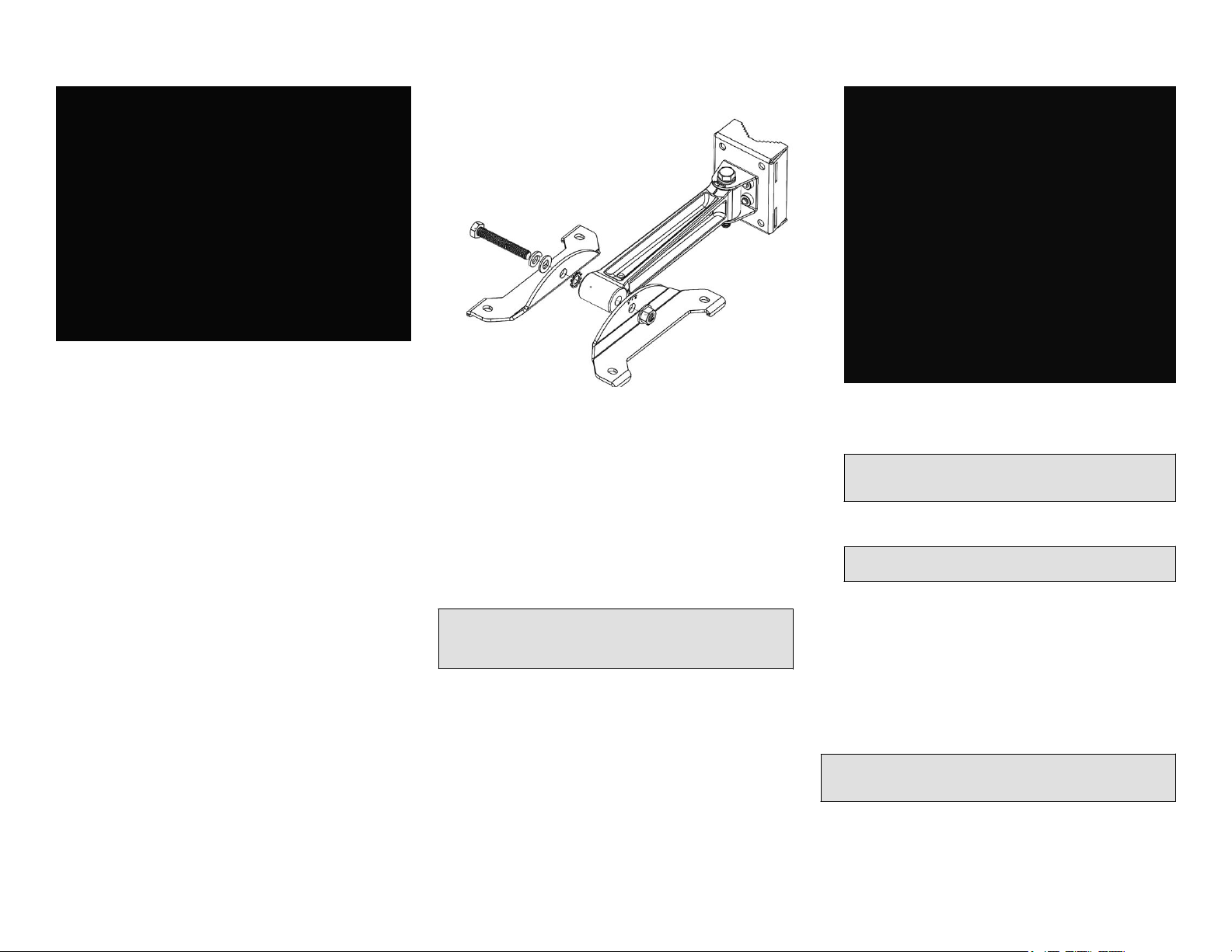
FIGURE 8 Horizontal mounting with Long Linkage Arm
FIGURE 10 Additional orientation vie
w of the
attachment of Linkage Bracket and U-joint Bracket to AP
bracket
FIGURE 11 Attaching the AP br
acket to the AP
1. Loosely assemble the linkage bracket (A), the U-joint bracket
(C), one serr
bolt and washer set (D).
ated external-tooth lock washer (B), and one M8
FIGURE 9 Attaching the Linkage Bracket to the U-joint
Bracket
2. Set the azimuth required by the AP.
Tighten the M8 bolt to 13.6 N.m (10 ft-lbs.)
3.
4. Continue with Step 5: Attaching the AP Bracket to the
Linkage Bracket on page 3.
Step 5: Attaching the AP Bracket to the Linkage Bracket
Attach the AP bracket to the linkage bracket using the included
bolt, nut, lock washer, at washer, serrated external-tooth
washer shown in Figure 10.
The AP bracket attaches to the linkage bracket using an M8 bolt
and washer set. The linkage bracket is symmetrical, and either
end can be attached to the AP bracket.
NOTE: Mak
serrated external-tooth lock washer on the inside of the AP
bracket anges. This ensures that the elevation adjustment
does not change.
e sure that linkage bracket is installed with its
As described in Step 4: Mounting the Linkage Br
U-Joint Bracket on page 2, loosely assemble the AP bracket
(shown in Figure 10), the linkage bracket (A in Figure 9), the
second serrated external-tooth lock washer (B in Figure 9),
and the second M8 bolt and washer set (D in Figure 9).
acket to the
Step 6: Attaching the AP Bracket to the Access Point
1. Place the AP bracket on to the back side of the AP so that the
four larger screw holes on the bracket align with the four
screw holes on the AP. Make sure that the end of the AP
bracket with the hoisting loop is on the same side as the AP
PoE IN port.
2. Use four 0.5-inch x 0.250-28 hex bolts with split lock and at
washer sets to mount the AP br
bolts to 2.5-3.0 N.m or 22-27 in-lbs.
CAUTION! Mak
0.5 inch. If a screw is longer than 0.5 inch, it can damage
the AP chassis.
3. If required, suspend the AP by attaching a carabiner to the
hoisting loop on the AP br
NOTE: This kit may include e
washers. You may use the extras wherever required.
4. Continue with Step 7: Setting the Ele
the Elevation Bolt on page 3.
e sure that the screws are no longer than
acket to the AP. Tighten the
acket.
xtra screws, nuts, and
vation and Tightening
Step 7: Setting the Elevation and Tightening the Elevation Bolt
1. Set the elevation required by the AP.
2. Tighten the M8 bolt to13.6 N.m (10 ft-lbs.)
3. Continue with Step 8: Earth Grounding the AP on page 3.
Step 8: Earth Grounding the AP
CAUTION! Using the factory-supplied gr
screw/washer set, connect a good earth ground to the AP
chassis ground point (Figure 12).
ound wire and ground
Copyright © 2018 ARRIS Enterprises LL
Published 09 July 2018, Part Number 800-71412-001 Rev A2
C. All rights reserved. Page 3 of 4
Page 4
NOTE: The color coding of gr
Before completing this step, check your local wiring standards
for guidance.
Using the factory-supplied ground wire and ground screw/
washer set, connect a good earth gr
ground point (Figure 12).
CAUTION! The Q910 AP includes one 12 mm stainless
steel M6x1 earth gr
washers. Make sure that any replacement screw is no
longer than 12 mm. If a screw is longer than 12 mm, it can
damage the AP chassis.
ound wires varies by region.
ound to the AP chassis
ound screw with split lock and at
Congratulations! You have mounted your Q910 access point.
Step 10: Checking the LED Lights
The LED lights verify the installation of AP
Once connected, AP will power on and automatically connect to
Ruckus Cloud over the Internet to congure itself. You will see
some activity and after 5-10 minutes all lights should turn solid
Green or solid Amber (LTE LED).
If any light is o or ashing, see the following table to help you
troubleshoot the issue.
Light Troubleshooting Action
.
FIGURE 12 Connect good earth gr
ound to AP here
Step 9: Installing the Security Cable
1.
Thread the security cable through the mounting bracket (A)
and through the eye on the cable itself (B), as shown in
Figure 13.
2. Attach the safety cable to the AP (C) in Figure 13.
FIGURE 13 Attaching the Security Cable
PWR Check Power, Ethernet connections and PoE
(802.3at T
ype-2 (PoE+) Certied) switch.
EMS Check Internet connection and network/
rewall settings.
EPC Check Internet connection and network/
rewall settings.
SYNC Ensure at least one AP in the network is near
an unobstructed window for a good GPS
signal.
LTE For additional guidance, use the Ruckus Cloud
or contact Customer Support.
For more Information
The AP is now operational and can be further managed by the
Ruckus Cloud service. For more information, refer to the
appropriate Ruckus Wireless Cloud documentation or visit
http://support.ruckuswireless.com
Copyright Notice and Proprietary
Information
Copyright © 2018 Ruckus Networks, an ARRIS
company. All rights reserved.
The Ruckus, Ruckus Wireless, Ruckus logo, and Big
Dog design trademarks are registered in the U.S. and
other countries. Other names and brands mentioned
in this document or website may be claimed as the
property of Ruckus or others.
Copyright © 2018 ARRIS Enterprises LL
Published 09 July 2018, Part Number 800-71412-001 Rev A2
C. All rights reserved. Page 4 of 4
 Loading...