

Page 1
®
R&S
SMW200A
Vector Signal Generator
Getting Started
(><êD2)
1412922002
Version 21
Getting Started
Page 2

This document describes the R&S®SMW200A, stock no. 1412.0000.02 and its
options.
© 2019 Rohde & Schwarz GmbH & Co. KG
Mühldorfstr. 15, 81671 München, Germany
Phone: +49 89 41 29 - 0
Fax: +49 89 41 29 12 164
Email: [email protected]
Internet: www.rohde-schwarz.com
Subject to change – Data without tolerance limits is not binding.
R&S® is a registered trademark of Rohde & Schwarz GmbH & Co. KG.
Trade names are trademarks of the owners.
1412.9220.02 | Version 21 | R&S®SMW200A
The following abbreviations are used throughout this manual: R&S®SMW200A is abbreviated as
R&S SMW, R&S®SMU200A is abbreviated as R&S SMU, R&S®WinIQSIM2TM is abbreviated as
R&S WinIQSIM2, R&S®VISA is abbreviated as R&S VISA.
Page 3
R&S®SMW200A
Contents
1 Safety Information................................................................. 7
2 Key Features.......................................................................... 9
3 Documentation Overview....................................................11
3.1 Getting Started Manual.......................................................................11
3.2 User Manuals and Help.......................................................................11
3.3 Tutorials............................................................................................... 12
3.4 Service Manual....................................................................................12
3.5 Instrument Security Procedures....................................................... 12
Contents
3.6 Basic Safety Instructions................................................................... 12
3.7 Data Sheets and Brochures............................................................... 12
3.8 Release Notes and Open Source Acknowledgment (OSA).............13
3.9 Application Notes, Application Cards, White Papers, etc...............13
4 Preparing for Use.................................................................15
4.1 Putting into Operation........................................................................ 15
4.1.1 EMI Suppression...................................................................................16
4.1.2 Unpacking and Checking the Instrument.............................................. 17
4.1.3 Accessory List.......................................................................................17
4.1.4 Placing or Mounting the Instrument...................................................... 18
4.1.5 Connecting AC Power...........................................................................20
4.1.6 Turning the Instrument On and Off....................................................... 20
4.1.7 Functional Check.................................................................................. 22
4.1.8 Default Settings.....................................................................................23
4.1.9 Checking the Supplied Options and Licenses...................................... 24
4.2 Connecting USB Devices................................................................... 24
3Getting Started 1412.9220.02 ─ 21
Page 4
R&S®SMW200A
4.3 Setting Up a Network (LAN) Connection.......................................... 25
4.3.1 Connecting the Instrument to the Network............................................26
Contents
5 Instrument Tour................................................................... 29
5.1 Front Panel Tour..................................................................................29
5.1.1 Touchscreen..........................................................................................30
5.1.2 Keys...................................................................................................... 32
5.1.2.1 Utility Keys............................................................................................ 32
5.1.2.2 On/Standby........................................................................................... 33
5.1.2.3 Function Keys....................................................................................... 33
5.1.2.4 Keypad..................................................................................................34
5.1.2.5 Navigation Controls...............................................................................34
Rotary Knob.......................................................................................... 35
Navigation Keys.................................................................................... 35
Display Keys......................................................................................... 35
5.1.3 Connectors............................................................................................36
5.2 Rear Panel Tour...................................................................................38
5.2.1 Connectors............................................................................................40
6 Trying Out the Instrument...................................................47
6.1 Generating an Unmodulated Carrier................................................. 48
6.2 Generating a Digitally Modulated Signal.......................................... 51
6.3 Triggering the Instrument with an External Signal.......................... 53
6.4 Enabling and Configuring a Marker Signal...................................... 60
6.5 Routing the Signal through the Instrument and Defining the Output
Connectors.......................................................................................... 61
6.6 Verifying the Generated Signal with the Graphics Display.............66
6.7 Saving and Recalling Settings...........................................................70
6.8 Generating an EUTRA/LTE Signal..................................................... 73
4Getting Started 1412.9220.02 ─ 21
Page 5
R&S®SMW200A
6.9 Using the System Configuration Capabilities for MIMO Setups.... 77
Contents
7 System Overview................................................................. 83
7.1 Brief Introduction to the Instrument's Concept............................... 83
7.1.1 The Signal Flow at a Glance.................................................................83
7.1.2 Internal Baseband Source ("Baseband" Blocks)...................................86
7.1.3 Digital Baseband Input and Output ("BB Input" and "I/Q Digital" Blocks)
.............................................................................................................. 87
7.1.4 Fading Simulator ("Fading" Blocks)...................................................... 88
7.1.5 Additional White Gaussian Noise ("AWGN" Blocks).............................88
7.1.6 "I/Q Stream Mapper" Block................................................................... 88
7.1.7 I/Q Modulator ("I/Q Mod" Blocks)..........................................................89
7.1.8 Analog I/Q Output ("I/Q Analog" Blocks)...............................................89
7.1.9 RF and Analog Modulations ("RF" Blocks)........................................... 89
7.2 Applications Examples of the R&S SMW......................................... 90
7.2.1 Transmit Diversity Test (MISO Scenario).............................................. 91
7.2.2 Receive Diversity Test (SIMO Scenario)...............................................92
7.2.3 Generation of Signals for Testing of WCDMA Handover (Two Cells)... 93
7.2.4 Generation of an EUTRA/LTE 8x2 MIMO Signal for UE Tests..............94
7.2.5 Generation of an LTE Test Signal with Carrier Aggregation and 2x2
MIMO each Component Carrier............................................................95
7.2.6 Generation of a WLAN 802.11ad Signal with 1.76 GHz Bandwidth......96
8 Instrument Control.............................................................. 97
8.1 Possible Ways to Operate the Instrument........................................97
8.2 Means of Manual Interaction..............................................................98
8.3 Understanding the Display Information............................................99
8.3.1 Status Bar........................................................................................... 100
8.3.2 Block Diagram.....................................................................................100
5Getting Started 1412.9220.02 ─ 21
Page 6
R&S®SMW200A
8.3.3 Taskbar............................................................................................... 102
8.3.4 Additional Display Characteristics.......................................................103
8.4 Accessing the Functionality............................................................ 105
8.5 Entering Data.....................................................................................106
8.5.1 Entering Numeric Parameters.............................................................107
8.5.2 Entering Alphanumeric Parameters.................................................... 107
8.5.3 Undo and Redo Actions...................................................................... 108
8.6 Getting Information and Help.......................................................... 108
8.6.1 Using the Tutorials.............................................................................. 110
8.7 Remote Control................................................................................. 113
8.8 Remote Operation over VNC............................................................114
Contents
Index....................................................................................115
6Getting Started 1412.9220.02 ─ 21
Page 7
R&S®SMW200A
Safety Information
1 Safety Information
The product documentation helps you to use the R&S SMW safely and efficiently.
Follow the instructions provided here and in the printed "Basic Safety Instructions". Keep the product documentation nearby and offer it to other users.
Intended use
The R&S SMW is designated for the development, production and verification of
electronic components and devices in industrial, administrative, and laboratory
environments. Use the R&S SMW only for its designated purpose. Observe the
operating conditions and performance limits stated in the data sheet.
Where do I find safety information?
Safety information is part of the product documentation. It warns you about the
potential dangers and gives instructions how to prevent personal injuries or damage caused by dangerous situations. Safety information is provided as follows:
●
The printed "Basic Safety Instructions" provide safety information in many languages and are delivered with the R&S SMW.
●
Throughout the documentation, safety instructions are provided when you
need to take care during setup or operation.
7Getting Started 1412.9220.02 ─ 21
Page 8
R&S®SMW200A
Safety Information
8Getting Started 1412.9220.02 ─ 21
Page 9
R&S®SMW200A
Key Features
2 Key Features
The R&S SMW is a new high-performance signal generator developed to meet
demanding customer requirements. Offering excellent signal characteristic and
straightforward and intuitive operation, the signal generator makes signal generation fast and easy.
Outstanding key features of the R&S SMW are:
●
Frequency range from 100 kHz to 3/6/7.5/12.75/20/31.8/40/44 GHz
●
Optional second RF path with 100 kHz up to 3/6/12.75/20 GHz
●
Up to 2 GHz I/Q modulation bandwidth (in RF) with internal baseband
●
Wideband baseband and vector signal generator in one box
●
Support of all important digital standards such as 5G NR, LTE incl eMTC/NBIoT, 3GPP FDD/HSPA/HSPA+, GSM/EDGE/EDGE evolution, CDMA2000® /
1xEV-DO, WLAN IEEE 802.11a/b/g/n/j/p/ac/ad/ax
●
Generating signals for radar module and receiver tests
●
Versatile configuration: from single-path vector signal generator to multichannel MIMO receiver tester
●
Optional integrated fading simulator with up to 160 MHz bandwidth
●
Ideal for MIMO, MSR, or LTE-Advanced applications thanks to up to eight signal sources and up to 32 fading channels
●
Implementation of all key MIMO fading scenarios such as 2x2, 3x3, 4x4, 8x4,
4x8 and 2x4x4 using a single instrument
●
Internal digital adding of baseband signals, with frequency and level offset
●
Excellent signal quality for high accuracy in spectral and modulation measurements
●
Intuitive operation via touchscreen with block diagram as key element
●
Graphical signal monitoring at practically every point in the signal flow
●
SCPI macro recorder and code generator for generating executable remote
control code from manual operating steps (for MATLAB®, CVI, etc.)
For a detailed specification, refer to the data sheet.
9Getting Started 1412.9220.02 ─ 21
Page 10
R&S®SMW200A
Key Features
10Getting Started 1412.9220.02 ─ 21
Page 11
R&S®SMW200A
Documentation Overview
User Manuals and Help
3 Documentation Overview
This section provides an overview of the R&S SMW user documentation. Unless
specified otherwise, you find the documents on the R&S SMW product page at:
www.rohde-schwarz.com/manual/smw200a
3.1 Getting Started Manual
Introduces the R&S SMW and describes how to set up and start working with the
product. Includes basic operations, typical measurement examples, and general
information, e.g. safety instructions, etc. A printed version is delivered with the
instrument.
3.2 User Manuals and Help
Separate manuals for the base unit and the software options are provided for
download:
●
Base unit manual
Contains the description of all instrument modes and functions. It also provides an introduction to remote control, a complete description of the remote
control commands with programming examples, and information on maintenance, instrument interfaces and error messages. Includes the contents of the
getting started manual.
●
Software option manual
Contains the description of the specific functions of an option. Basic information on operating the R&S SMW is not included.
The contents of the user manuals are available as help in the R&S SMW. The
help offers quick, context-sensitive access to the complete information for the
base unit and the software options.
All user manuals are also available for download or for immediate display on the
Internet.
11Getting Started 1412.9220.02 ─ 21
Page 12
R&S®SMW200A
Documentation Overview
Data Sheets and Brochures
3.3 Tutorials
The R&S SMW provides interactive examples and demonstrations on operating
the instrument in form of tutorials. A set of tutorials is available directly on the
instrument.
3.4 Service Manual
Describes the performance test for checking the rated specifications, module
replacement and repair, firmware update, troubleshooting and fault elimination,
and contains mechanical drawings and spare part lists.
The service manual is available for registered users on the global
Rohde & Schwarz information system (GLORIS, https://gloris.rohde-
schwarz.com).
3.5 Instrument Security Procedures
Deals with security issues when working with the R&S SMW in secure areas. It is
available for download on the Internet.
3.6 Basic Safety Instructions
Contains safety instructions, operating conditions and further important information. The printed document is delivered with the instrument.
3.7 Data Sheets and Brochures
The data sheet contains the technical specifications of the R&S SMW. It also lists
the options and their order numbers and optional accessories.
The brochure provides an overview of the instrument and deals with the specific
characteristics.
12Getting Started 1412.9220.02 ─ 21
Page 13
R&S®SMW200A
Application Notes, Application Cards, White Papers, etc.
See www.rohde-schwarz.com/brochure-datasheet/smw200a
Documentation Overview
3.8 Release Notes and Open Source Acknowledgment (OSA)
The release notes list new features, improvements and known issues of the current firmware version, and describe the firmware installation.
The open source acknowledgment document provides verbatim license texts of
the used open source software.
See www.rohde-schwarz.com/firmware/smw200a
3.9 Application Notes, Application Cards, White Papers, etc.
These documents deal with special applications or background information on
particular topics.
See www.rohde-schwarz.com/application/smw200a and www.rohde-
schwarz.com/manual/smw200a
13Getting Started 1412.9220.02 ─ 21
Page 14
R&S®SMW200A
Documentation Overview
Application Notes, Application Cards, White Papers, etc.
14Getting Started 1412.9220.02 ─ 21
Page 15
R&S®SMW200A
Preparing for Use
Putting into Operation
4 Preparing for Use
● Putting into Operation..................................................................................... 15
● Connecting USB Devices................................................................................24
● Setting Up a Network (LAN) Connection.........................................................25
4.1 Putting into Operation
This section describes the basic steps to be taken when setting up the R&S SMW
for the first time.
Risk of injury due to disregarding safety information
Observe the information on appropriate operating conditions provided in the
data sheet to prevent personal injury or damage to the instrument. Read
and observe the basic safety instructions provided with the instrument, in
addition to the safety instructions in the following sections. In particular:
●
Do not open the instrument casing.
Risk of instrument damage due to inappropriate operating conditions
Specific operating conditions are required to ensure accurate measurements and to avoid damage to the instrument. Observe the information on
appropriate operating conditions provided in the basic safety instructions
and the instrument's data sheet.
15Getting Started 1412.9220.02 ─ 21
Page 16
R&S®SMW200A
Instrument damage caused by electrostatic discharge
Electrostatic discharge (ESD) can damage the electronic components of the
instrument and the device under test (DUT). Electrostatic discharge is most
likely to occur when you connect or disconnect a DUT or test fixture to the
instrument's test ports. To prevent electrostatic discharge, use a wrist strap
and cord and connect yourself to the ground, or use a conductive floor mat
and heel strap combination.
Risk of instrument damage due to inappropriate operating conditions
An unsuitable operating site or test setup can damage the instrument and
connected devices. Before switching on the instrument, observe the information on appropriate operating conditions provided in the data sheet. In
particular, ensure the following:
Preparing for Use
Putting into Operation
●
All fan openings are unobstructed and the airflow perforations are unimpeded. A minimum distance of 10 cm to other objects is recommended.
●
The instrument is dry and shows no sign of condensation.
●
The instrument is positioned as described in the following sections.
●
The ambient temperature does not exceed the range specified in the
data sheet.
●
Signal levels at the input connectors are all within the specified ranges.
●
Signal outputs are connected correctly and are not overloaded.
4.1.1 EMI Suppression
Electromagnetic interference (EMI) may affect the measurement results.
To suppress generated Electromagnetic Interference (EMI),
●
Use suitable shielded cables of high quality. For example use double-shielded
RF, BNC and LAN cables (CAT6 STP).
Note: USB cables are of varying and often poor quality. Therefore, check the
quality of each individual USB cable as described in the service manual.
●
Always terminate open cable ends.
16Getting Started 1412.9220.02 ─ 21
Page 17
R&S®SMW200A
●
Use the cable R&S SMU-Z6 for connection to the DIG I/Q interfaces of the
instrument. The required cable is available under part number 1415.0201.02.
●
For connection to the HS DIG I/Q interfaces of the instrument, use:
– QSFP+ passive copper cable with max. length of 3 m
– Active optical cable with max. power class 2 module (2.0 W max. power
consumption)
Note the EMC classification in the data sheet.
Preparing for Use
Putting into Operation
4.1.2 Unpacking and Checking the Instrument
Unpack the R&S SMW carefully and check the contents of the package.
●
Check if all items listed on the delivery note, including this getting started
manual, are included in the delivery.
●
Check the R&S SMW for any damage.
If the contents are damaged, immediately contact the carrier who delivered
the package.
Packing material
Retain the original packing material. If the instrument needs to be transported or shipped later, you can use the material to protect the control elements and connectors.
Risk of injury during transportation
The carrying handles at the front and side of the casing are designed to lift
or carry the instrument. Do not apply excessive force to the handles. If a
handle is ripped off, the falling instrument can cause injury.
Be aware of the weight of the instrument when lifting it. Observe the information on transporting heavy instruments in the basic safety instructions
provided with the instrument.
4.1.3 Accessory List
The instrument comes with the following accessories:
17Getting Started 1412.9220.02 ─ 21
Page 18
R&S®SMW200A
●
Power cable
●
Getting Started printed manual
Preparing for Use
Putting into Operation
4.1.4 Placing or Mounting the Instrument
The R&S SMW is designed for use under laboratory conditions, either on a bench
top or in a rack using the standard rackmount kit.
Bench top operation
If the R&S SMW is operated on a bench top, the surface must be flat. The instrument can be used in horizontal position, standing on its feet, or with the support
feet on the bottom extended.
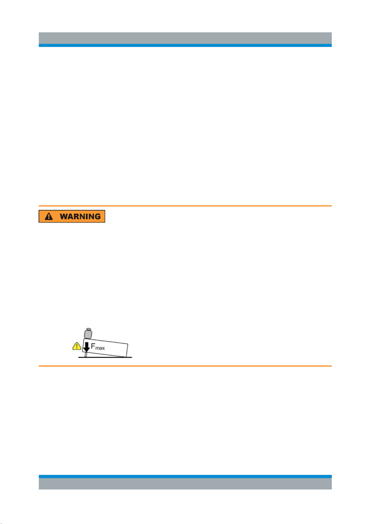
Risk of injury if feet are folded out
The feet can fold in if they are not folded out completely or if the instrument
is shifted. Collapsing feet can cause injury or damage the instrument.
●
Fold the feet completely in or out to ensure stability of the instrument.
Never shift the instrument when the feet are folded out.
●
When the feet are folded out, do not work under the instrument or place
anything underneath.
●
The feet can break if they are overloaded. The overall load on the folded-out feet must not exceed 500 N.
18Getting Started 1412.9220.02 ─ 21
Page 19
R&S®SMW200A
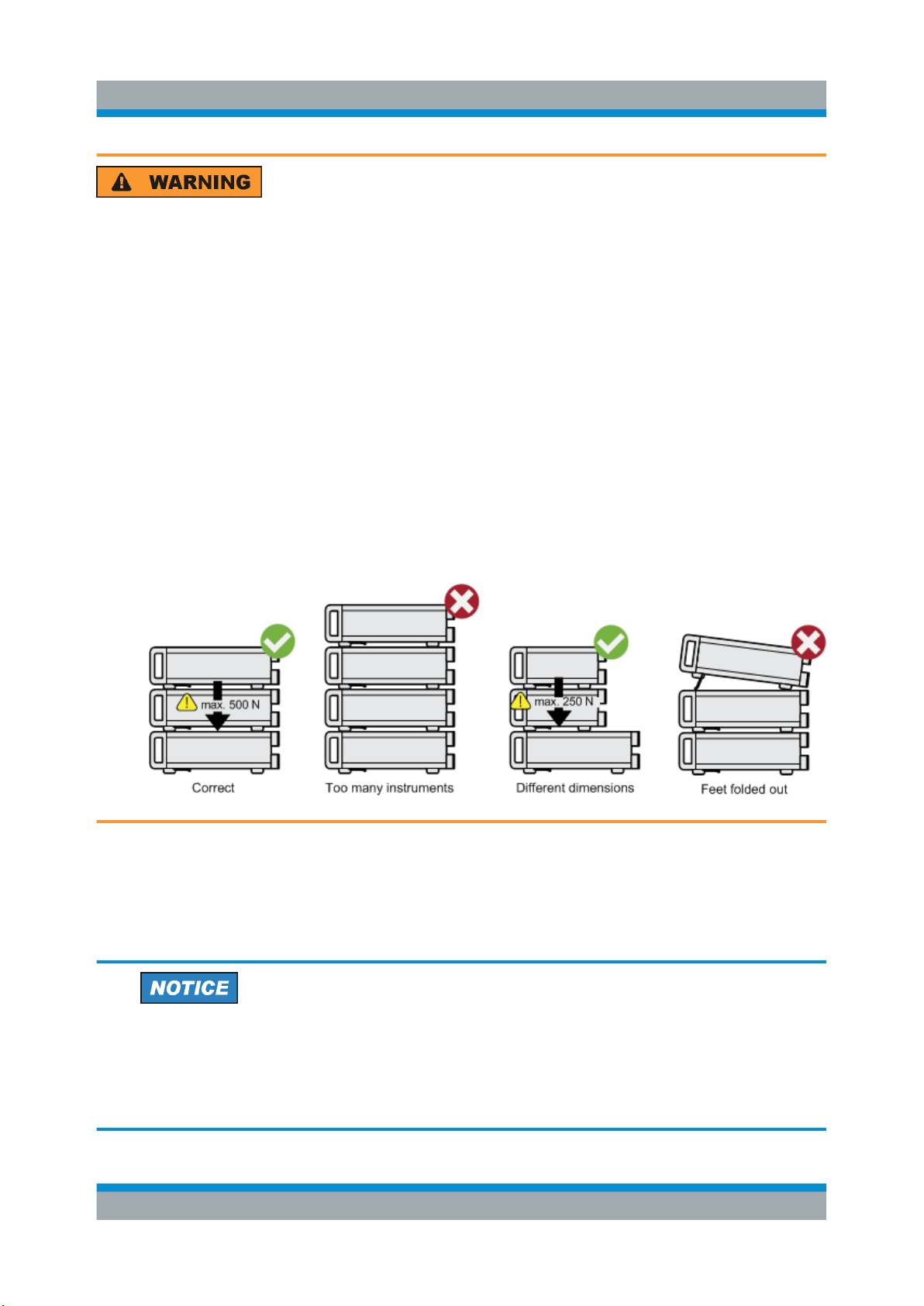
Risk of injury when stacking instruments
A stack of instruments can tilt over and cause injury if not stacked correctly.
Furthermore, the instruments at the bottom of the stack can be damaged
due to the load imposed by the instruments on top.
Observe the following instructions when stacking instruments:
●
Never stack more than three instruments. If you need to stack more
than three instruments, install them in a rack.
●
The overall load imposed on the lowest instrument must not exceed
500 N.
●
It is best if all instruments have the same dimensions (width and length).
If you need to stack smaller instruments on the top, the overall load
imposed on the lowest instrument must not exceed 250 N.
Preparing for Use
Putting into Operation
●
If the instruments have foldable feet, fold them in completely.
Mounting in a rack
The R&S SMW can be installed in a rack using a rack adapter kit (Order No. see
data sheet). The installation instructions are part of the adapter kit.
Risk of instrument damage due to insufficient airflow in a rack
If you mount several instruments in a rack, you need an efficient ventilation
concept to ensure that the instruments do not overheat. Insufficient airflow
for a longer period can disturb the operation and even cause damage.
19Getting Started 1412.9220.02 ─ 21
Page 20
R&S®SMW200A
Preparing for Use
Putting into Operation
4.1.5 Connecting AC Power
The R&S SMW is equipped with an AC power supply connector, that can be operated with different AC power voltages. Once it is connected, the instrument automatically adjusts to the given voltage. Refer to the data sheet for the requirements of voltage and frequency. There is no need to set the voltage manually or
change fuses.
The AC supply and power switch is at the rear of the unit.
To connect the AC supply
► Connect the R&S SMW to the AC power source using the supplied power
cable.
Note: Since the instrument is designed in compliance with standard EN
61010-1 safety class I, it must only be connected to an outlet that has a
ground contact.
Characteristics of the AC power supply:
●
100 V to 240 V AC
●
50 Hz to 60 Hz; 400 Hz
●
7.3 A to 4.6 A
4.1.6 Turning the Instrument On and Off
To turn on the R&S SMW
1. Connect the instrument to the AC supply.
2. Turn on the main AC power switch at the rear panel of the R&S SMW (posi-
tion "I" (on)).
The instrument is supplied with AC power.
Warm-up time for OCXO
When the instrument is switched on, the OCXO requires an extended
warm-up time (see data sheet).
20Getting Started 1412.9220.02 ─ 21
Page 21
R&S®SMW200A
To start the R&S SMW
Starting the R&S SMW requires that it is connected and turned on.
► At the front panel, press the [On/Standby] key briefly.
The instrument boots the operating system and starts the instrument firmware.
After booting, the instrument is in the state before the last power off (standby
or ready), indicated by the color of the [On/Standby] key's LEDs:
● Green: the R&S SMW is running and ready for operation.
All modules are power-supplied.
● Orange: the R&S SMW is in standby mode (main AC power switch is in
position "I").
The standby power mode keeps the power switch circuits and the ovencontrolled crystal oscillator OCXO active. In this state, it is safe to switch
off the AC power and disconnect the instrument from the power supply.
To switch between standby and ready state, briefly press the [On/Standby]
key.
Preparing for Use
Putting into Operation
If a previous session was terminated regularly, the instrument uses the last setup
with the relevant instrument settings.
► To set up a new configuration, press the [PRESET] key to return the instru-
ment to its defined reset/preset state.
To customize the start settings, e.g. to recall previously saved settings:
●
Use the [SAVE/RCL] function or
●
Define the [USER] key.
21Getting Started 1412.9220.02 ─ 21
Page 22
R&S®SMW200A
To shut down and turn off the R&S SMW
Risk of losing data
If you switch off the running instrument using the rear panel switch or by
disconnecting the power cord, the instrument loses its current settings. Furthermore, program data can be lost.
Press the On/Standby key first to shut down the application properly.
1. Press the [On/Standby] key.
The current setup is saved, the operating system shuts down and sets the
instrument to standby state.
The [On/Standby] LED must be orange.
Preparing for Use
Putting into Operation
2. Turn off the main AC power switch at the rear panel of the R&S SMW (posi-
tion "0" (off)).
The instrument is no longer supplied with AC power.
Turning off the AC power
You can leave the AC power on permanently. Switching off is required only
if the instrument must be disconnected from all power supplies.
4.1.7 Functional Check
When the instrument is switched on, it automatically monitors the main functions.
A detected fault is indicated by an "Error" message displayed in the "Info" line of
the instrument together with a brief error description. For an in-depth identification
of the error, tap on the "Info" indication. In response, a description of the errors is
displayed. For more information, refer to the "Troubleshooting and Error Messages" section in the user manual.
In addition to the automatic monitoring, the R&S SMW offers the following capabilities to assure correct functioning:
●
Internal adjustments
Select the "System Config > Setup > General > Internal Adjustments" to
access the dialog for performing and configuring the adjustments settings.
22Getting Started 1412.9220.02 ─ 21
Page 23
R&S®SMW200A
●
Self-test
A self-test is provided for service purposes ("System Config > Setup > Maintenance > Selftest").
●
Test points
If necessary for service purposes, internal test points can be queried. These
tests are protected test procedures, which can be accessed if protection level
2 is disabled. The corresponding procedure is described in the Service Manual.
Preparing for Use
Putting into Operation
4.1.8 Default Settings
When the instrument is switched on, it is not the preset state that is active, but the
state that was set before the instrument was switched off. Use the [PRESET]
function to return the instrument to its defined preset state every time a new configuration is required or the current setup is no longer relevant.
The R&S SMW offers a four-stage preset concept:
●
Preset of one individual parameter
The selective preset on a parameter basis is triggered over the "Preset this
parameter" function in the context menu
●
Preset of the settings belonging to a digital standard or associated with one
dialog
Most of the dialog boxes provide a special "Set to Default" function that resets
the settings associated to the corresponding dialog. This function is available
for all digital modulation settings and the ARB generator.
These settings are identical to the settings called up using the [PRESET] key.
●
Preset of the instrument to a predefined state
The [PRESET] key calls up a defined instrument setup. All parameters and
switching states are preset (also the states of inactive operating modes). The
default instrument settings provide a reproducible initial basis for all other settings. However, functions that concern the integration of the instrument into a
measurement setup are not changed, for example reference oscillator source
settings.
●
Preset of the instrument to its factory settings
The instrument can also be forced to load its default factory settings, except
that the security settings are not affected. To access the corresponding dialog
box, select the "Taskbar > System Config > Setup > Settings > Factory Preset" function.
23Getting Started 1412.9220.02 ─ 21
Page 24
R&S®SMW200A
Connecting USB Devices
For more information and an overview of the settings affected by the preset
and factory preset function, see section "Restoring the (Default) Instrument
Configuration" in the user manual.
User-defined instrument states can be stored and called up using the
"Setup > Save/Recall" function or the [SAVE/RCL] key.
Preparing for Use
4.1.9 Checking the Supplied Options and Licenses
The instrument can be equipped with both, hardware and firmware options. To
check whether the installed options correspond to the options indicated on the
delivery note, proceed as follows:
1. Press the [SETUP] key.
2. Select "Instrument Assembly > Hardware Config" and "Software / Options".
A list with hardware and firmware information is displayed.
3. Check the availability of the hardware options as indicated in the delivery
note.
For an overview of the available options, refer to the data sheet.
4.2 Connecting USB Devices
The USB interfaces of the R&S SMW allow you to connect USB devices, including USB hubs directly to the instrument. Due to the large number of available
USB devices, there is almost no limit to the expansions that are possible with the
R&S SMW.
The following list shows various USB devices that can be useful:
●
Memory stick for easy transfer of data to/from a computer (for example firmware updates)
●
Keyboard or mouse to simplify the entry of data, comments, filenames, etc.
●
Power sensors of the R&S NRP families
All USB devices can be connected to or disconnected from the instrument during
operation.
24Getting Started 1412.9220.02 ─ 21
Page 25
R&S®SMW200A
Setting Up a Network (LAN) Connection
Connecting a USB storage device
When a USB storage device like a memory stick, a CD-ROM drive, or a hard disk
is connected, it is detected automatically. The device is made available as a new
drive (/usb). The name of the drive is manufacturer-dependent.
Connecting a keyboard
A keyboard is detected automatically when it is connected. The default keyboard
layout is English – US.
Connecting a mouse
A mouse is detected automatically when it is connected.
Preparing for Use
4.3 Setting Up a Network (LAN) Connection
The R&S SMW is equipped with a network interface and can be connected to an
Ethernet LAN (local area network). Provided the appropriate rights have been
assigned by the network administrator, the interface can be used, for example:
●
To transfer data between a controller and the instrument, for example to run a
remote control program.
●
To access or operate the instrument from a remote computer using the
Ultr@VNC program (or a similar tool, like another VNC client or any Web
browser supporting Java).
●
To transfer data from a remote computer and back, for example using network
folders.
●
To use power sensors with netwok capability, e.g. the R&S NRP LAN power
sensors.
This section describes how to configure the LAN interface.
Accessing operating system
No access to the operating system is required for normal operation.
All necessary system settings can be made in the "Setup" dialog.
25Getting Started 1412.9220.02 ─ 21
Page 26
R&S®SMW200A
Setting Up a Network (LAN) Connection
Preparing for Use
4.3.1 Connecting the Instrument to the Network
There are two methods to establish a LAN connection to the instrument:
●
A non-dedicated network (Ethernet) connection from the instrument to an
existing network
●
A dedicated network connection (Point-to-point connection) between the
instrument and a single computer
For addressing, both the instrument and the computer reqiure an IP address. The
address information is usually assigned to the devices automatically, depending
on the network capabilities.
If the IP address is not assigned automatically, see "Assigning the IP Address" in
the R&S SMW user manual, for information on how to assign the address manually.
To set up a network (LAN) connection
Risk of network failure
Consult your network administrator before performing the following tasks:
●
Connecting the instrument to the network
●
Configuring the network
●
Changing IP addresses
Errors can affect the entire network.
► Connect the instrument to the network or to a single PC.
If the instrument is connected to the LAN, the operating system automatically
detects the network connection and activates the required drivers.
By default, the instrument is configured to use DHCP (dynamic host configuration protocol) configuration and to obtain the whole address information automatically.
When connected, the R&S SMW displays the address information on the
screen.
26Getting Started 1412.9220.02 ─ 21
Page 27
R&S®SMW200A
Setting Up a Network (LAN) Connection
Risk of network connection failure
Network cables and cable connectors of poor quality, or failures in the autonegotiation process, can cause network connection failures.
If the network connection to the instrument fails, check the network infrastructure and contact your network administrator.
For details, see section "Troubleshooting and Error Messages" in the
R&S SMW user manual.
Preparing for Use
27Getting Started 1412.9220.02 ─ 21
Page 28
R&S®SMW200A
Preparing for Use
Setting Up a Network (LAN) Connection
28Getting Started 1412.9220.02 ─ 21
Page 29
R&S®SMW200A
Instrument Tour
Front Panel Tour
5 Instrument Tour
The following topics help you get familiar with the instrument and perform the first
steps:
●
Front Panel Tour
●
Rear Panel Tour
This section explains the control elements and the connectors of the R&S SMW
with the aid of the front and rear views. For specifications of the interfaces, refer
to the data sheet.
5.1 Front Panel Tour
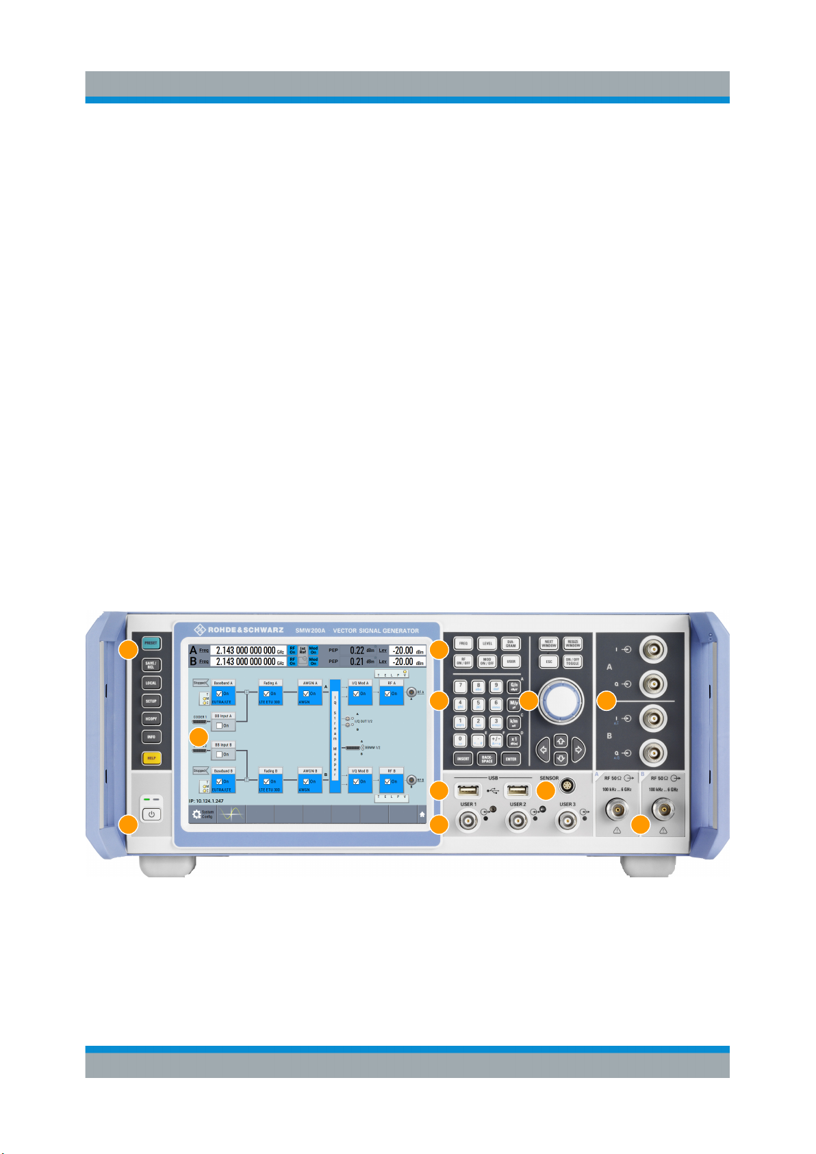
This section provides an overview of the control elements and connectors on the
front panel of the R&S SMW. On the rear panel, you find all further connectors of
the unit, see Chapter 5.2, "Rear Panel Tour", on page 38. The user interface
can be displayed on a remote PC station used to manually remote control the
instrument.
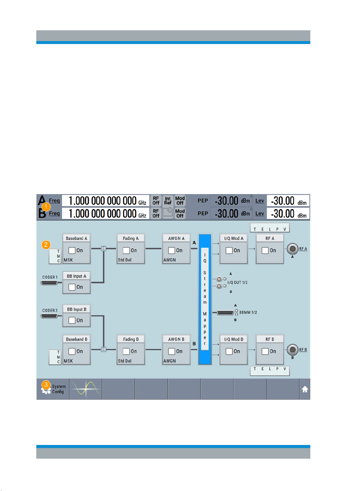
2
1
3
4
5 6 7
8 9
10
11
Figure 5-1: Front panel view
1 = Touchscreen
2 = Utility keys
3 = [On/Standby]
4 = Function keys
5 = Keypad
29Getting Started 1412.9220.02 ─ 21
Page 30
R&S®SMW200A
Instrument Tour
Front Panel Tour
6 = Navigation controls
7 = I/Q input connectors
8 = USB connectors
9 = SENSOR connector
10 = USER x input/output connectors
11 = RF A/RF B output connectors
5.1.1 Touchscreen
The block diagram and the most important settings are displayed on the screen
on the front panel. Additionally, the screen display provides status and setting
information and allows you to quickly reconfigure the signal flow. The screen is
touch-sensitive, offering an alternative means of user interaction for quick and
easy handling of the instrument.
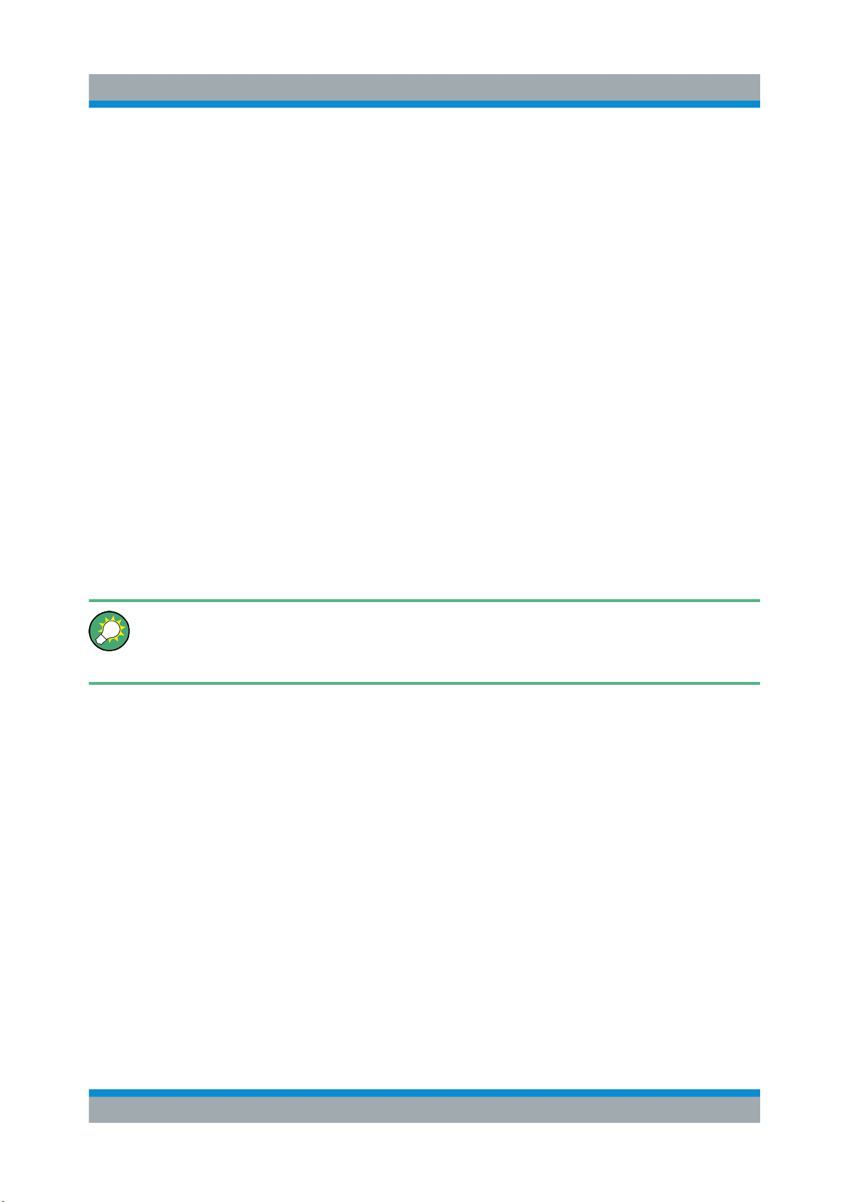
Figure 5-2: Touchscreen elements
30Getting Started 1412.9220.02 ─ 21
Page 31
R&S®SMW200A
Instrument Tour
Front Panel Tour
1 = Status bar (frequency and level display)
2 = Block diagram
3 = Taskbar/softkey bar
A touchscreen is a screen that is touch-sensitive. It reacts in a specified way
when a particular element on the screen is tapped by a finger. Any user interface
element that can be clicked by a mouse pointer can also be tapped on the screen
to trigger the same behavior.
Using the touchscreen, the following tasks (among others) can be performed by
the tap of your finger:
●
Changing a setting
●
Selecting new settings
●
Scrolling through the list of parameters
●
Saving or recalling settings
●
Routing the signal flow
●
Opening and closing dialogs
See also Chapter 6, "Trying Out the Instrument", on page 47.
To imitate a right-click by mouse using the touchscreen, for example to
open a context-sensitive menu for a specific item, touch and hold the
screen for about 1 second.
31Getting Started 1412.9220.02 ─ 21
Page 32
R&S®SMW200A
Risk of touchscreen damage
Inappropriate tools or excessive force can damage the touchscreen.
Observe the following instructions when operating the touchscreen:
●
Never touch the screen with ball point pens or other sharp objects, use
your fingers instead.
As an alternative, you can use a stylus pen with a smooth soft tip.
●
Never apply excessive force to the screen. Touch it gently.
●
Never scratch the screen surface, for example with a finger nail.
●
Never rub the screen surface strongly, for example with a dust cloth.
For instructions on cleaning the screen, see the Maintenance chapter in
the R&S SMW user manual.
Instrument Tour
Front Panel Tour
5.1.2 Keys
5.1.2.1 Utility Keys
The utility keys cause the R&S SMW to return to a defined instrument state and
provide information on the instrument and assistance.
For more information, refer to chapter "General Instrument Functions" in the user
manual.
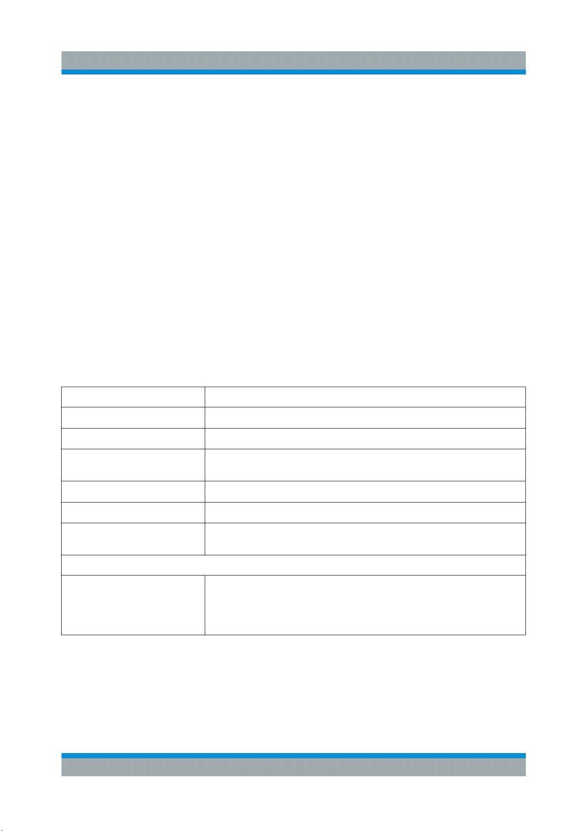
Table 5-1: Utility keys
Utility Key Assigned functions
[PRESET] Sets the instrument to a defined state
[SAVE/RCL] Saves and loads instrument setting
Accesses the file manager
[LOCAL] Switches from remote control to local (manual) control
[SETUP] Accesses the general instrument settings
[HCOPY] Opens the "Hardcopy" dialog for storing the current display in a file
[INFO] Displays status messages, error messages, and warnings
[HELP] Displays context-sensitive help text
32Getting Started 1412.9220.02 ─ 21
Page 33
R&S®SMW200A
Instrument Tour
Front Panel Tour
5.1.2.2 On/Standby
The [On/Standby] key switches the instrument from the standby to the ready state
or vice versa.
●
In the ready state, the LED is green. The instrument is ready for operation.
●
In the standby state, the LED is orange. The standby power mode keeps the
power switch circuits and the oven-controlled crystal oscillator OCXO active.
In this state, it is safe to switch off the AC power and disconnect the instrument from the power supply.
5.1.2.3 Function Keys
Function keys provide access to most common generator settings and functions.
A detailed description of the corresponding functions is provided in the user manual.
Table 5-2: Function keys
Function key Assigned functions
[FREQ]
[LEVEL]
[Diagram] Brings the block diagram to the foreground. Active dialogs are
[RF ON/OFF]
[MOD ON/OFF]
[USER] Key with a customizable function. You can define the action to be
Function execution (in navigation controls area)
[ON/OFF TOGGLE]
1)
The entry field that was active last is activated. Press the key again to activate
Activates frequency entry.
Activates level entry.
minimized.
Switches the RF output on and off.
Switches the modulations on and off.
executed.
●
Switches highlighted elements or a function block on and off.
●
Switches between two or more settings, e.g. items of selection lists. At the end of a list, the cursor is set on the first
entry again.
1)
1)
2)
2)
the entry field of the other path.
2)
Status is displayed in the "Status bar". The key switches off all RF signals/
modulations; press the key again to restore the last active status.
33Getting Started 1412.9220.02 ─ 21
Page 34
R&S®SMW200A
Instrument Tour
Front Panel Tour
5.1.2.4 Keypad
The keypad is used to enter alphanumeric parameters, including the corresponding units. It contains the following keys:
Table 5-3: Keys on the keypad
Type of key Description
Alphanumeric keys Enter numbers and (special) characters in edit dialog boxes.
Decimal point Inserts a decimal point "." at the cursor position.
Sign key Changes the sign of a numeric parameter. In the case of an
alphanumeric parameter, inserts a "-" at the cursor position.
Unit keys
(G/n dBμV, M/μ μV, k/m mV
and x1 dB(m))
[INSERT] key Toggles between insert and overwrite mode
[ESC] key Closes all kinds of dialog boxes, if the edit mode is not active.
[Backspace] key If an alphanumeric entry has already been started, this key dele-
[Enter] key
These keys add the selected unit to the entered numeric value
and complete the entry.
In the case of level entries (e.g. in dB) or dimensionless values,
all units have the value "1" as multiplying factor. Thus, they have
the same function as an [Enter] key.
Quits the edit mode, if the edit mode is active. In dialog boxes
that contain a "Cancel" button it activates that button.
For "Edit" dialog boxes the following mechanism is used:
●
If data entry has been started, it retains the original value
and closes the dialog box.
●
If data entry has not been started or has been completed, it
closes the dialog box.
tes the character to the left of the cursor.
Has the same effect as pressing the rotary knob
●
Concludes the entry of dimensionless entries. The new value
is accepted.
●
With other entries, this key can be used instead of the
default unit key.
●
In a dialog box, selects the default or focused element.
●
Calls the next dialog level.
●
Confirms and closes open input windows.
5.1.2.5 Navigation Controls
The navigation controls include a rotary knob, navigation keys, and the display
keys. They allow you to navigate within the display or within dialog boxes.
34Getting Started 1412.9220.02 ─ 21
Page 35
R&S®SMW200A
Instrument Tour
Front Panel Tour
Rotary Knob
The rotary knob has several functions:
●
Increments (clockwise direction) or decrements (counterclockwise direction)
the instrument parameter at a defined step width in the case of a numeric
entry.
●
Moves the selection, e.g. to a function block in the block diagram
●
Shifts the selection bar within focused areas (e.g. lists).
●
Acts like the [Enter] key, when it is pressed.
Navigation Keys
The navigation keys can be used alternatively to the rotary knob to navigate
through dialog boxes, diagrams, or tables.
Table 5-4: Navigation keys
Type of key Description
[Up/Down] Key The [Up] and the [Down] key does the following:
●
In a numeric edit dialog box, increase or decrease the instrument parameter.
●
In a list, scroll forward and backward through the list entries.
●
In a table, move the selection bar vertically.
●
In windows or dialog boxes with vertical scrollbar, move the
scrollbar.
[Left/Right] Key The [Left] and the [Right] key does the following:
●
In an alphanumeric edit dialog box, move the cursor.
●
In a list, scroll forward and backward through the list entries.
●
In a table, move the selection bar horizontally.
●
In windows or dialog boxes with horizontal scrollbar, move
the scrollbar.
Display Keys
The display keys arrange different windows on the display.
35Getting Started 1412.9220.02 ─ 21
Page 36
R&S®SMW200A
Instrument Tour
Front Panel Tour
Table 5-5: Display keys
Display key Assigned functions
[NEXT WINDOW] Toggles between the active dialogs
[RESIZE WINDOW] Adjusts the size of the active dialog to use the whole height of
the display.
[ESC] Closes all kinds of dialog boxes, if the edit mode is not active.
Quits the edit mode, if the edit mode is active. In dialog boxes
that contain a "Cancel" button it activates that button.
For "Edit" dialog boxes the following mechanism is used:
●
If data entry has been started, it retains the original value
and closes the dialog box.
●
If data entry has not been started or has been completed, it
closes the dialog box.
5.1.3 Connectors
The RF and I/Q connectors and various others interface connectors are on the
front panel.
I/Q, I/Q Bar
I and Q inputs for external analog modulation signal directly fed into the I/Q modulator.
One pair of I and Q inputs are available per installed RF path.
The I/Q connectors are used to input single-ended signals or the positive signal
input for differential signals. The I/Q Bar connectors are used to input the negative signal for differential signals.
For more information, see chapter "Overview of the Input and Output Signals and
Connectors" in the user manual.
USB
USB (universal serial bus) interfaces of type A (host USB).
●
Connection of peripherals such as mouse or keyboard
●
Connection of memory stick for file transfer
●
Firmware update
Note: Further USB interface type A (host USB) and a USB interface type B (USB
Device) are available on the rear panel.
See also Chapter 4.2, "Connecting USB Devices", on page 24.
36Getting Started 1412.9220.02 ─ 21
Page 37
R&S®SMW200A
Instrument Tour
Front Panel Tour
SENSOR
Connector for R&S NRP sensors.
A power sensor is connected to the R&S SMW by inserting the male connector.
To disconnect, pull the connector by its sleeve. You cannot disconnect the sensor
simply by pulling at the cable or the rear part of the connector.
The R&S SMW supports the use of R&S NRP power sensors in various ways
including the use as a power viewer.
USER x
Multipurpose connectors. The input/output signal has to be defined.
The Table 5-6 lists the signals assigned to the USER x connectors in the default
instrument state.
Table 5-6: Default configuration of the USER x connectors
USER connector Direction Default assigned signal
1 Output Baseband A Marker 1
2 Output Baseband A Marker 2
3 Input Global Trigger 1
A dedicated LED indicates the connector status:
●
Green: an input connector
●
Yellow: an output connector
●
No light: the connector is not active
See also chapter "Local and Global Connector Settings" in the user manual.
RF A/RF B
Outputs for RF signal of path A and path B.
NOTICE! Maximum input levels. Do not overload the RF output. The maximum
permissible back-feed is specified in the data sheet.
The connector type depends on the installed frequency option, see Table 5-7.
Table 5-7: Overview of RF connector types depending on the frequency range
Required option Connector type
RF A: R&S SMW-B103/-B106
RF B: R&S SMW-B203/-B206
RF A: R&S SMW-B112
RF B: R&S SMW-B212
N female
Test port adapter, PC 3.5 mm female
37Getting Started 1412.9220.02 ─ 21
Page 38
R&S®SMW200A
Required option Connector type
Instrument Tour
Rear Panel Tour
RF A: R&S SMW-B120
RF B: R&S SMW-B220
RF: R&S SMW-B131/-B140/-B140N Test port adapter, PC 2.92 mm female
RF: R&S SMW-B144/-B144N PC 1.85 mm female, including protective
Test port adapter, PC 3.5 mm female
adapter
NOTICE! Risk of RF connector and cable damage. If you tighten the connectors
too strongly, you can damage the cables and connectors. If you do not tighten the
connectors enough, the measurement results can be inaccurate.
Always use an appropriate torque wrench suitable for this type of connector and
apply the torque specified in the application note 1MA99.
If your instrument is equipped with a test port adapter, refer also to 1MA100.
The application notes are available on the Internet and provide additional information on care and handling of RF connectors.
Rohde & Schwarz offers appropriate torque wrenches for various connectors. For
ordering information, see the R&S SMW data sheet or product brochure.
Note: The R&S SMW-B144/-B144N connectors come with a protective adapter to
prevent the sensitive connector from damage.
It is available as a spare part, and can be replaced if damaged. Contact your
Rohde & Schwarz support center or www.customersupport.rohdeschwarz.com for
information.
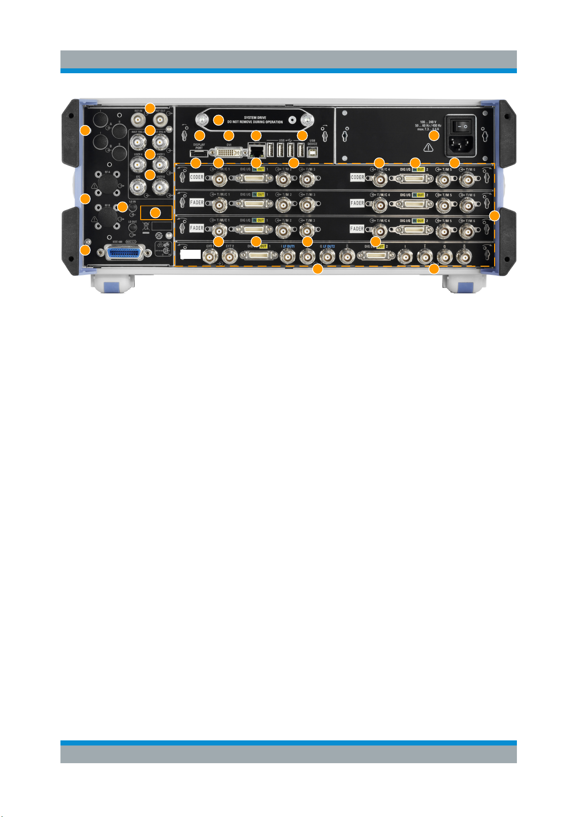
5.2 Rear Panel Tour
This section provides an overview of the connectors on the rear panel of the
instrument. For technical data of the connectors, refer to the data sheet.
38Getting Started 1412.9220.02 ─ 21
Page 39
R&S®SMW200A
4
1
5
Instrument Tour
Rear Panel Tour
9
10 11 12 13 14
6
7
2
3
8
21
BBMM
16
15
18 19
17a
17b
16 16 16
17b
20a
17a
20b
22
Figure 5-3: Rear panel view of instrument equipped with R&S SMW-B10 and R&S SMW-
B13T (standard baseband)
1, 2 = Connectors for use in a rack
3 = IEC 625/IEEE 488 connector
4 = REF IN/REF OUT connectors
5 = INST TRIG x connectors
6 = USER x connectors
7 = EFC connectors
8 = LO IN/LO OUT connectors
9 = HDD/SSD system drive
10, 11 = Display Port, DVI connectors
12 = LAN connectors
13 = USB/USB Device connectors
14 = AC power supply connection and main power switch
15 = Board designation (CODER, FADER, BBMM)
16 = T/M/C and T/M connectors
17a, 17b = DIG I/Q connectors
18 = EXT x connectors
19 = LF OUT x connectors
20a, b = I/Q, I/Q Bar connectors
21 = Serial number (six digits in the string 1412.0000.02-<serial number>-<checksum>)
22 = R&S SMW-B10, R&S SMW-B13T and R&S SMW-B14 boards location
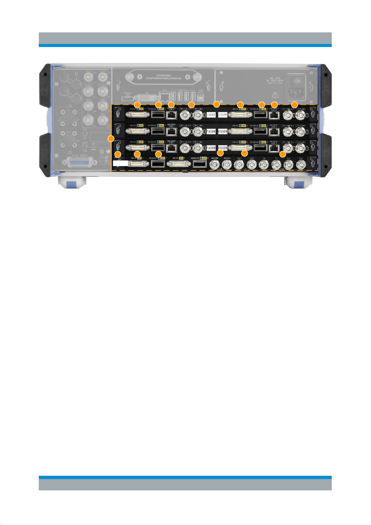
The rear panel view differs in particular if the standard or wideband baseband
options are installed. The Figure 5-4 shows a detail view of the rear panel. Shown
are only the different boards.
39Getting Started 1412.9220.02 ─ 21
Page 40
R&S®SMW200A
Instrument Tour
Rear Panel Tour
2
7
3a
8
654a
1
2
BBMM
3a
3b 9
5
4a
4b
6
Figure 5-4: Detail view: Rear panel of instrument equipped with R&S SMW-B9 and
R&S SMW-B13XT (wideband baseband)
1 = R&S SMW-B9, R&S SMW-B13XT and R&S SMW-B15 boards location
2 = Board designation (CODER, BBMM, FADER)
3a, 3b = DIG I/Q connectors (connectors on the FADER board are provided for future use)
4a, 4b = HS DIG I/Q connectors (connectors on the FADER board are provided for future use)
5 = ADV DATA/CTRL connectors
6 = T/M/C and T/M connectors
7 = ADV TRIG and ADV CLK connectors
8 = EXT x connectors
9 = I/Q, I/Q Bar connectors
5.2.1 Connectors
I/Q
Rear panel connectors, recommended for use of the instrument in a 19" rack.
See also "Mounting in a rack" on page 19.
RF A/RF B
Rear panel connectors for the first RF path (option R&S SMW-B81/-B83) and the
second RF path (option R&S SMW-B82/-B84). These options are recommended
for use of the instrument in a 19" rack.
See also "Mounting in a rack" on page 19.
IEC 625/IEEE 488
GPIB-bus interface for remote control of the instrument.
40Getting Started 1412.9220.02 ─ 21
Page 41
R&S®SMW200A
Instrument Tour
Rear Panel Tour
The IEC 625 interface is in compliance with IEEE488 and SCPI. A computer for
remote control can be connected via this interface. To set up the connection, we
recommend that you use a shielded cable.
Note: To avoid electromagnetic interference (EMI) caused by open lines, always
terminate any connected IEC-bus cable with an instrument or a controller.
See also "Annex: Hardware Interfaces" and chapter "Network and Remote Control" in the user manual.
REF IN/REF OUT
Input/output for external reference signal.
The external reference is used for both paths.
INST TRIG x
Input for external trigger of sweeps and list mode.
USER x
Multipurpose connectors. The input/output signal has to be defined.
The Table 5-8 lists the signals assigned to the USER x connectors in the default
instrument state.
Table 5-8: Default configuration of the USER x connectors
USER connector Direction Default assigned signal
4 Input Global Trigger 2
5 Output Signal Valid A
6 Not used None
A dedicated LED indicates the connector status:
●
Green: an input connector
●
Yellow: an output connector
●
No light: the connector is not active
See also chapter "Local and Global Connector Settings" in the user manual.
EFC
Input connector for an EFC (external frequency control) signal for electronic tuning of the internal reference frequency.
LO IN/LO OUT
Option: R&S SMW-B90
41Getting Started 1412.9220.02 ─ 21
Page 42
R&S®SMW200A
Local oscillator input and output for phase-coherent RF signal:
●
LO IN: Input of phase coherence signal
●
LO OUT: Output of phase coherence signal
NOTICE! Risk of damaging components. Always use an appropriate 8 mm torque
wrench to tighten SMA connectors. Limit the tightening torque to 60 Ncm. Never
use an open-end wrench.
System drive (HDD/SSD)
Hard disk drive (HDD) or solid-state drive (SSD); the SSD requires option
R&S SMW-B93.
Concerning security concerns the hard disk can be removed from the instrument,
but it is bound to the specific R&S SMW. Therefore, it cannot be exchanged
between different instruments.
NOTICE! Risk of instrument damage and data loss. Removing the hard disk while
the instrument is in operation leads to data loss or even instrument damage.
Do not remove the hard disk during operation.
Instrument Tour
Rear Panel Tour
Display Port, DVI
Provided for future use.
LAN
The LAN interface can be used to connect the R&S SMW to a local network for
remote control, remote operation, and data transfer.
USB/USB Device
●
Four female USB type A connectors, to connect devices like a keyboard, a
mouse, a memory stick, or the R&S NRP-Z3/Z4 cable for the R&S NRP power
sensors
●
Female USB Device connector (USB type B), for example for remote control.
See also Chapter 4.2, "Connecting USB Devices", on page 24.
AC supply and power switch
The AC power supply connector and the main power switch are located in a unit
on the rear panel of the instrument.
Main power switch function:
●
Position 1: The instrument is in operation.
●
Position 0: The entire instrument is disconnected from the AC power supply.
For details, refer to Chapter 4.1.6, "Turning the Instrument On and Off",
on page 20.
42Getting Started 1412.9220.02 ─ 21
Page 43
R&S®SMW200A
Instrument Tour
Rear Panel Tour
T/M/C
Multipurpose input/output trigger/marker/clock connectors.
The number of connectors depend on the installed baseband options:
●
Standard baseband generator (R&S SMW-B10):
One T/M/C and two T/M connectors per board.
●
Wideband baseband generator (R&S SMW-B9):
One T/M/C and one T/M connectors per board
The input/output signal has to be defined. The Table 5-9 lists the configuration of
the local connectors in the default instrument state.
Table 5-9: Default configuration of the T/M/C connectors (standard baseband)
T/M/C connector
(Standard baseband)
1, 4 Output Clock Local clock signal for the par-
2, 5 Input Trigger Local trigger signal for the
3, 6 Output Marker 3 Marker output signal from the
Table 5-10: Default configuration of the T/M/C connectors (wideband baseband)
T/M/C connector Direction Default assigned signal
1 Output Symbol clock
2 Input External serial data
Direction Default assigned
signal
Remark
ticular baseband
particular baseband
particular baseband
A dedicated LED indicates the connector status:
●
Green: an input connector
●
Yellow: an output connector
●
No light: the connector is not active
See also chapters "Data, Clock and Control Signals and Sources in the Baseband" and "Local and Global Connectors" in the user manual.
DIG I/Q
Connectors for the input/output of a digital I/Q signal from and to a
Rohde & Schwarz instrument, like a signal generator, signal analyzer, the R&S
EX-IQ-BOX, or the R&S®CMW500.
The interfaces require the options listed in Table 5-11 (for details see the data
sheet).
43Getting Started 1412.9220.02 ─ 21
Page 44
R&S®SMW200A
Instrument Tour
Rear Panel Tour
Table 5-11: Overview of the DIG I/Q interfaces and the required options
Location Designation Required option
CODER boards CODER 1/2 In R&S SMW-B10, standard baseband generator
R&S SMW-B9, wideband baseband generator,
if "System Config > Mode = Advanced"
FADER boards FADER 1/2/3/4
In/Out
BBMM board BBMM 1/2 Out R&S SMW-B13/-B13T and
R&S SMW-B14, fading simulator
R&S SMW-K18, digital baseband output
R&S SMW-B13XT, if "System Config > Mode =
Advanced"
A dedicated LED indicates the connector status:
●
Green: an input connector
●
Yellow: an output connector
●
No light: the connector is not active
EXT x 1/2
Input for external analog modulation signals.
Any of the two inputs can be used for path A and path B.
LF OUT x
Option: R&S SMW-B13/-B13T
Output for internal LF generator signal.
Note: The output of the internal LF signal and the analog I/Q signal use the same
physical connectors.
These signals cannot be output at the same time.
See also data sheet and user manual, section "Analog Modulation".
I/Q, I/Q Bar
Direct (single-ended) or differential output for the analog I/Q signal.
The number of connectors depends on the installed baseband options:
●
Standard baseband (R&S SMW-B10 and R&S SMW-B13T)
Two single-ended analog and two differential outputs.
Output of differential signal requires option R&S SMW-K16.
●
Wideband baseband (R&S SMW-B9 and R&S SMW-B13XT)
Two single-ended analog or one differential output. Differential and singleended signals cannot be output at the same time.
Output of differential signal requires option R&S SMW-K17.
44Getting Started 1412.9220.02 ─ 21
Page 45
R&S®SMW200A
Instrument Tour
Rear Panel Tour
See also "Analog I/Q Output Settings" in the user manual.
ADV DATA/CTRL
Option: R&S SMW-B9/-B13XT and R&S SMW-K503/-K504
Interface for exchanging of external data and control signals.
See user manual R&S SMW-K501/-K502/-K503/-K504 Extended and Real-Time
Sequencing, Real-Time Control Interface.
ADV TRIG, ADV CLK
Option: R&S SMW-B9/-B13XT
Input and output for synchronization signal in multi-instrument setups.
See also "Multi-Instrument Setups" in the user manual.
HS DIG I/Q
Option: R&S SMW-B9/-B13XT
Connectors for the input/output of high-speed digital I/Q signals, for example,
from and to Rohde & Schwarz instruments.
The interfaces require the options listed in Table 5-12.
For more information, see data sheet.
Table 5-12: Overview of the HS DIG I/Q interfaces and the required options
Location of the interface Designation Required option
CODER board CODER 1/2 In R&S SMW-B9, wideband baseband
generator
BBMM board BBMM 1/2 Out R&S SMW-B13XT, wideband base-
band main module
R&S SMW-K19 for the output of digi-
tal signals
The interface is a QSFP+ (Quad Small Form-factor Pluggable) module. It supports max. bandwidth of up to 50 Gsample/s with optical active cables.
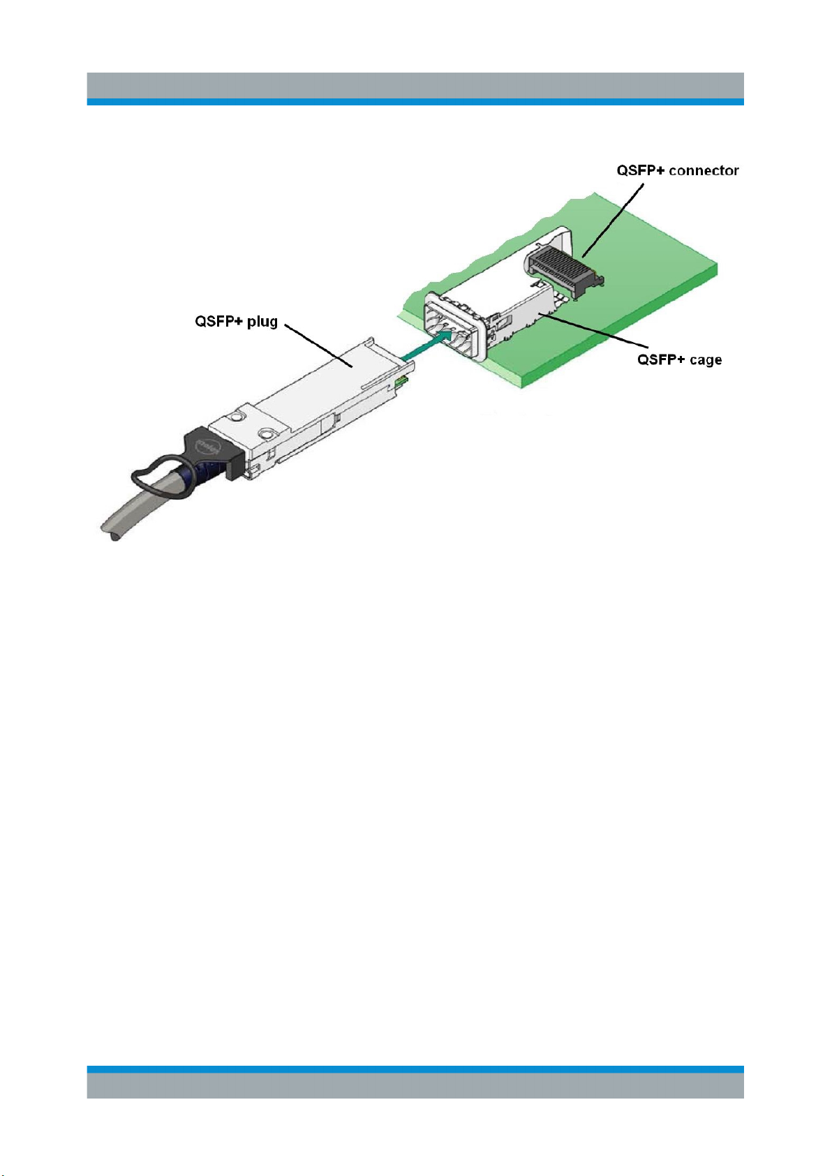
A QSFP+ socket on the instrument has two components: a QSFP+ connector and
a QSFP+ cage. The QSFP+ cable is equipped with the QSFP+ plug.
45Getting Started 1412.9220.02 ─ 21
Page 46
R&S®SMW200A
Instrument Tour
Rear Panel Tour
NOTICE! Risk of damaging the HS DIG I/Q interface.
Use active optical QSFP+ cable with max. power class 2 module (2.0 W max.
power consumption).
●
●
See also "I/Q Digital Output Settings" and "Digital Baseband Input Settings" in the
user manual.
To plug in the cable:
Hold the QSFP+ plug by its panes. The release tab must be upwards
oriented.
Insert it in the HS DIG I/Q cage and push it.
To disconnect the cable:
Do not pull the cable itself. Puling the cable can damage the cable
and the HS DIG I/Q connector.
Pull the release tab and pull the connector out of the HS DIG I/Q connector.
46Getting Started 1412.9220.02 ─ 21
Page 47
R&S®SMW200A
Trying Out the Instrument
6 Trying Out the Instrument
This chapter introduces the most important functions and settings of the
R&S SMW step by step. The complete description of the functionality and its
usage is given in the R&S SMW user manual. Basic instrument operation is
described in Chapter 8, "Instrument Control", on page 97.
See also:
●
"To start a tutorial in an interactive step-by-step mode" on page 110
Prerequisites
●
The instrument is set up, connected to the power supply, and started up as
described in Chapter 4, "Preparing for Use", on page 15.
●
Throughout this description, the term base unit describes a R&S SMW equipped with the options R&S SMW-B10, R&S SMW-B13, and R&S SMW-B103.
For the first signal generation tasks, you use the internal baseband and reference
signal, so you do not need any additional signal source. More complex signal
generation tasks, however, require an instrument equipped with additional options
and/or external signals. Each task description lists its prerequisites.
The screenshots in this description show a fully equipped instrument. Consider that, the block diagram displayed on your particular instrument can differ from the one used in the example.
The instrument is manually operated via the touchscreen. Try out the following:
● Generating an Unmodulated Carrier............................................................... 48
● Generating a Digitally Modulated Signal......................................................... 51
● Triggering the Instrument with an External Signal...........................................53
● Enabling and Configuring a Marker Signal......................................................60
● Routing the Signal through the Instrument and Defining the Output Connec-
tors.................................................................................................................. 61
● Verifying the Generated Signal with the Graphics Display..............................66
● Saving and Recalling Settings........................................................................ 70
● Generating an EUTRA/LTE Signal..................................................................73
● Using the System Configuration Capabilities for MIMO Setups......................77
47Getting Started 1412.9220.02 ─ 21
Page 48
R&S®SMW200A
Generating an Unmodulated Carrier
Trying Out the Instrument
6.1 Generating an Unmodulated Carrier
We start out by generating a simple unmodulated signal. The R&S SMW in this
example can be a base unit in its minimal configuration.
1. On the R&S SMW front panel, press the [PRESET] key to start out in a
defined instrument configuration.
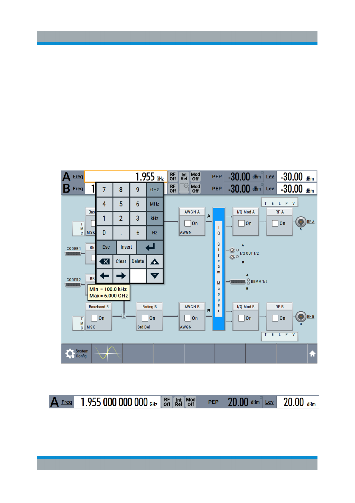
2. Set the frequency:
a) On the "Status Bar", tap the "A Freq" field.
b) On the on-screen keypad, enter 1.955 and press the "GHz" key.
The on-screen key pad closes and the frequency value is displayed.
3. On the "Status Bar", tap the "Lev" field and enter the level in the same way.
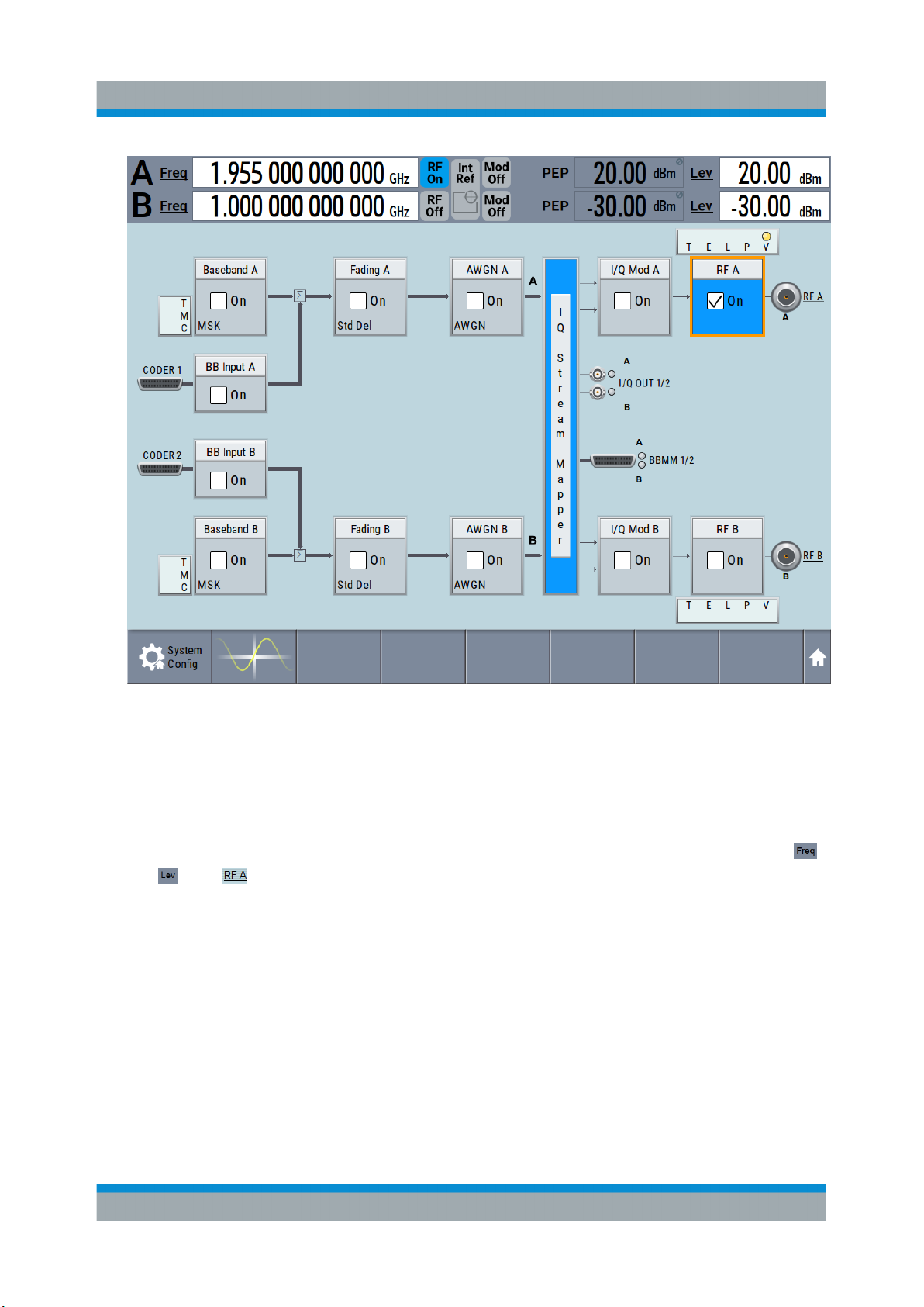
4. Select "Block Diagram > RF A Block > On" to enable the output of the gener-
ated unmodulated signal.
48Getting Started 1412.9220.02 ─ 21
Page 49
R&S®SMW200A
Trying Out the Instrument
Generating an Unmodulated Carrier
Figure 6-1: Block diagram: Generating an unmodulated signal
Tip: Alternative way to access the instrument functions. To fulfill the same
task, you can use other hot spots in the block diagram, the provided functions
under the "RF" block or the function front panel keys.
Try out the following:
● On the "Status Bar" and in the block diagram, tap the underlined labels ,
and .
Or:
● Select "Block Diagram > RF A" block, navigate through the context menu,
and use the settings provided in the "Frequency" and "Level" dialog.
49Getting Started 1412.9220.02 ─ 21
Page 50
R&S®SMW200A
Trying Out the Instrument
Generating an Unmodulated Carrier
To enable signal generation, enable the "RF On".
Or:
● Use the [FREQ], [LEVEL], and [RF ON/OFF] key on the front panel.
See also Chapter 8, "Instrument Control", on page 97.
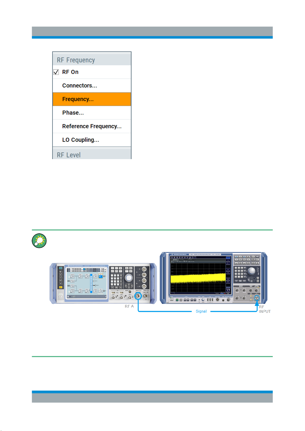
The 1.95 GHz signal is output at the RF A connector at the front panel of the
R&S SMW.
Connect RF A of the R&S SMW to a signal analyzer, for example
R&S®FSW, to display the generated signal.
Figure 6-2: Simplified test setup
For the required settings of the signal analyzer, refer to its user manual or
its online help.
50Getting Started 1412.9220.02 ─ 21
Page 51
R&S®SMW200A
Generating a Digitally Modulated Signal
Trying Out the Instrument
6.2 Generating a Digitally Modulated Signal
This example shows you how to generate a simple WCDMA-3GPP (QPSK 45°
offset) signal with the help of the "Custom Digital Modulation" functionality. The
minimum requirement for R&S SMW in this example is a base unit.
The initial situation is not the instrument's preset state but rather the configuration
described in Chapter 6.1, "Generating an Unmodulated Carrier", on page 48.
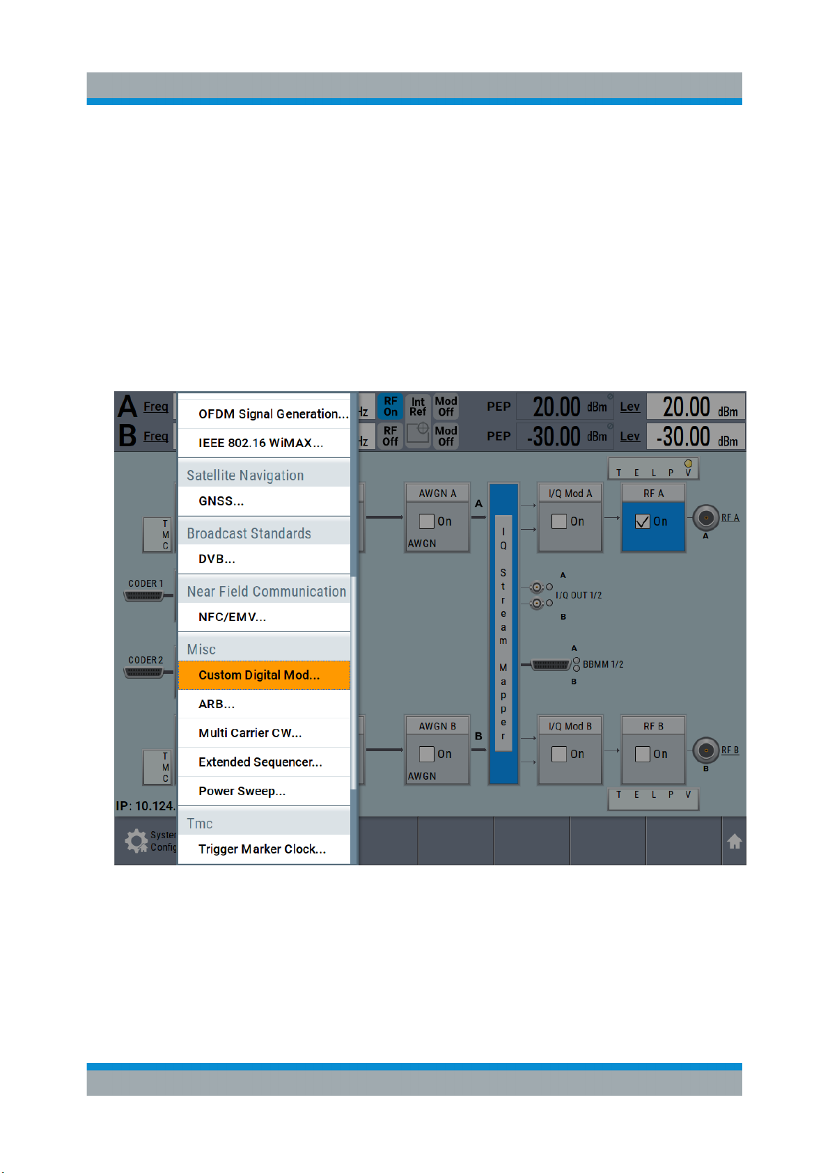
1. In the block diagram, select "Baseband A" and navigate to the section "Misc >
Custom Digital Mod...".
The "Custom Digital Modulation" dialog opens.
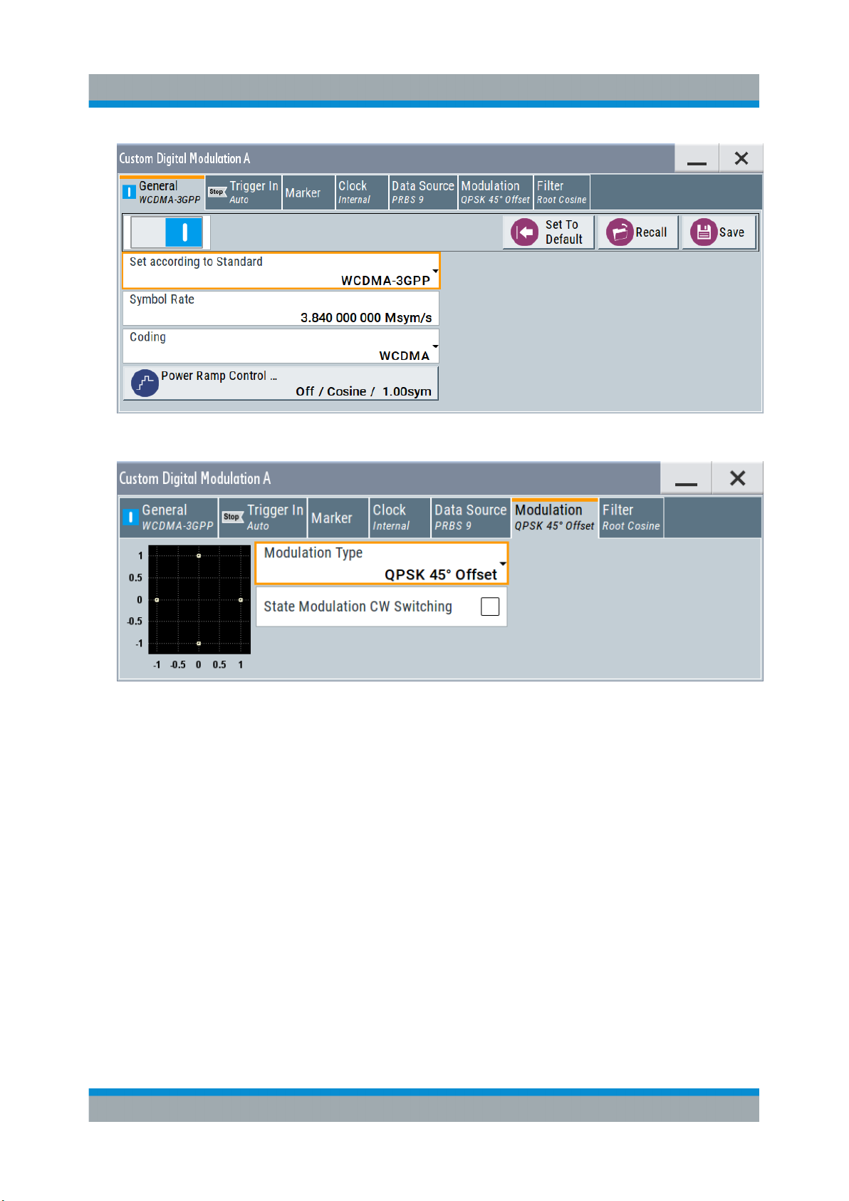
2. In the "Custom Digital Modulation" dialog, select "General > Set acc to standard > WCDMA-3GPP".
3. Select "General > State > On" to enable signal generation.
51Getting Started 1412.9220.02 ─ 21
Page 52
R&S®SMW200A
Trying Out the Instrument
Generating a Digitally Modulated Signal
4. Select the "Modulation" tab and observe the used "Modulation Type".
Figure 6-3: Display of the used modulation type
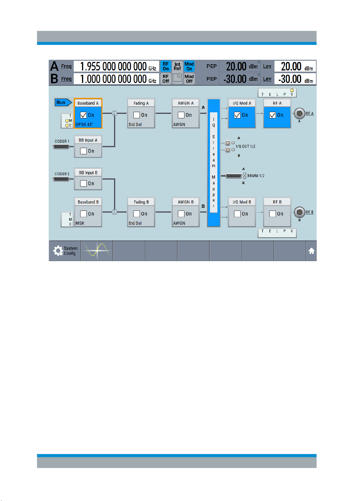
The instrument activates automatically "I/Q Mod A", uses the internal trigger
and clock signals, and generates a WCDMA-3GPP signal, modulated with a
QPSK 45° offset modulation.
52Getting Started 1412.9220.02 ─ 21
Page 53
R&S®SMW200A
Trying Out the Instrument
Triggering the Instrument with an External Signal
Figure 6-4: Block diagram: Generating a digitally modulated signal
6.3 Triggering the Instrument with an External Sig-
nal
The example configurations are rather theoretical cases, because you rarely use
the R&S SMW as a stand-alone instrument. Usually, the instrument would be
connected to a device under test (DUT) and/or other measurement equipment. As
a rule, whenever a test setup requires two or more devices, provide them with a
common reference frequency. Some test setups require control of the signal generation start and an exact generation start time, determined by a defined trigger
event, e.g. by triggering the instrument internally or externally from the DUT.
This example illustrates the general principle of external triggering and extends
the configuration performed in Chapter 6.2, "Generating a Digitally Modulated
53Getting Started 1412.9220.02 ─ 21
Page 54
R&S®SMW200A
Triggering the Instrument with an External Signal
Signal", on page 51 by the configuration of the required trigger signal and con-
nector settings.
In this example, we use the global USER connectors. Alternatively, you can
achieve the same configuration goal with the local T/M/C connectors.
This test setup requires one signal analyzer, like the R&S®FSW, as additional
equipment.
To start the signal generation in Baseband A synchronous to an external
global trigger signal
The configuration requires three main steps with the following goals:
1. Observe the current connector configuration and define an input connector for
the external global trigger signal.
See "To verify the current connector configuration" on page 54
Trying Out the Instrument
2. Configure Baseband A to use this external global trigger signal as trigger
source.
See "To reconfigure the trigger settings" on page 57
3. Connect the instrument and the external trigger source.
See "To connect the instrument and the external trigger source" on page 58
To verify the current connector configuration
The R&S SMW is equipped with multi-purpose bi-directional local T/M/C connectors and global USER connectors. Because the signal direction, input or output,
and the signal mapping are configurable, we recommend that you check the current configuration before cabling or further instrument's configurations.
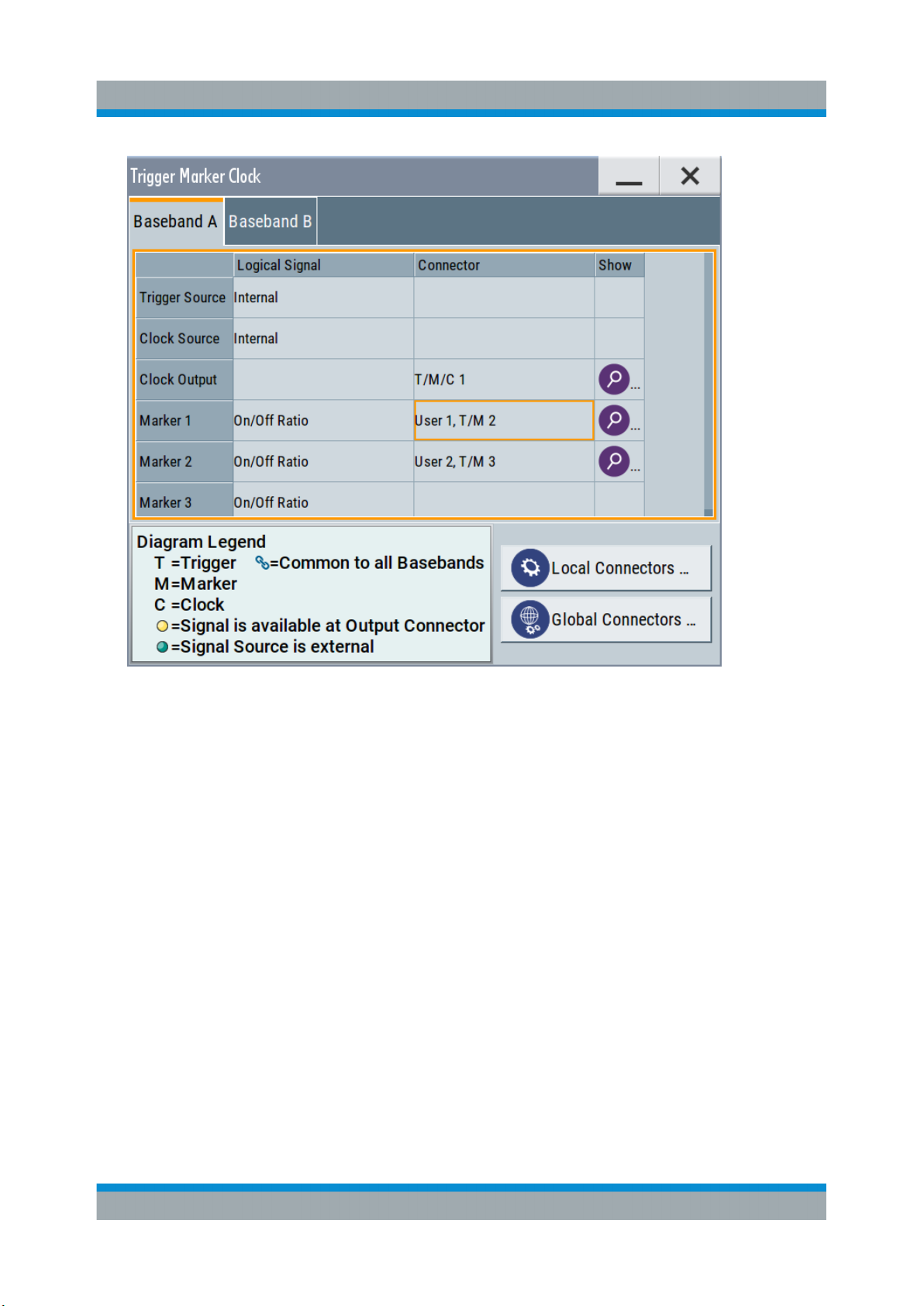
1. To display an overview of the current mapping of the logical signals to the connectors, perform one of the following:
● In the block diagram, select the Trigger/Marker/Clock status LEDs on the
left side of the "Baseband" block.
● Select "Baseband > Trigger Marker Clock".
54Getting Started 1412.9220.02 ─ 21
Page 55
R&S®SMW200A
Trying Out the Instrument
Triggering the Instrument with an External Signal
The instrument uses its internal trigger and clock signals, and the default mapping of the marker signals to the connectors.
2. To access the related connector settings, perform one of the following:
● Select "Global Connector Settings"
● Tap the connector name, for example select the connector "User 1, T/M 2"
55Getting Started 1412.9220.02 ─ 21
Page 56
R&S®SMW200A
Trying Out the Instrument
Triggering the Instrument with an External Signal
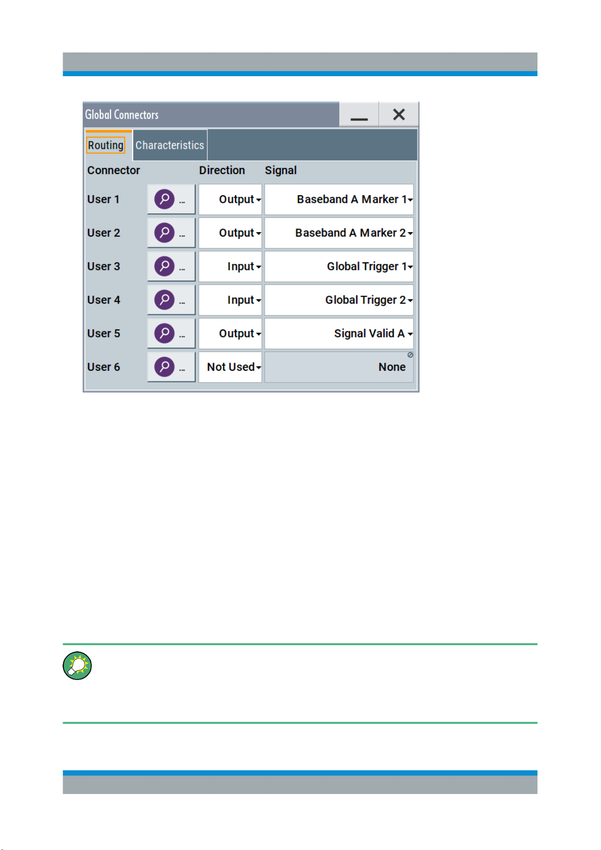
Figure 6-5: Signal mapping to the global connectors
The "Global Connectors" dialog displays the current connectors configuration.
The settings are configurable, but in this example we use the default mapping.
3. Alternatively, select "Block Diagram > Baseband > Misc > Custom Digital
Mod", select the "> Trigger In" tab and select "Local Connector Settings" or
"Global Connector Settings".
In the current mapping, the three global connectors USER x on the front panel
are configured as follows:
● "Marker 1/2" are output at the USER 1/2 connectors
● The USER 3 connector is an input for the "Global Trigger 1" signal.
Check the front panel of the R&S SMW. The USER 1/2 LEDs are yellow; the
USER 3 LED is green.
Find the physical location of each connector
Use the built-in "Trigger Marker Clock > Show " function to display the location of the selected connector. A blinking LED on the front/rear panel also
indicates the selected connector.
56Getting Started 1412.9220.02 ─ 21
Page 57
R&S®SMW200A
Triggering the Instrument with an External Signal
To reconfigure the trigger settings
We assume that the instrument is configured as described in Chapter 6.2, "Gen-
erating a Digitally Modulated Signal", on page 51 and the default connector map-
ping is maintained (see Figure 6-5).
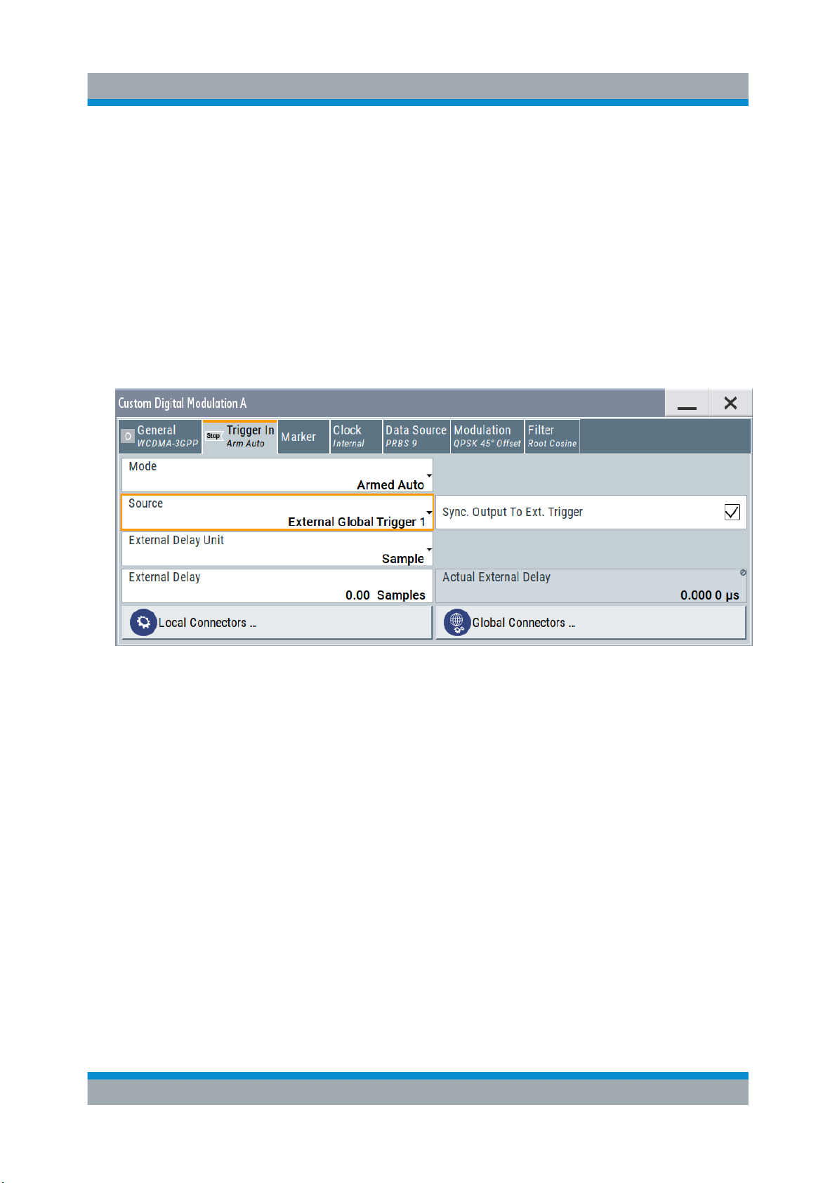
1. In the block diagram, select "Baseband > Misc > Custom Digital Mod > Trigger
In".
2. Select the following settings:
a) "Mode > Armed Auto"
b) "Source > External Global Trigger 1".
Trying Out the Instrument
The instrument expects an external global trigger event. In this current configuration (see Figure 6-5), the "Global Trigger 1" signal has to be supplied at the
input connector USER 3.
The Trigger/Marker/Clock status LEDs in the block diagram confirm that an
external trigger signal is selected; the signal generation is however stopped.
57Getting Started 1412.9220.02 ─ 21
Page 58
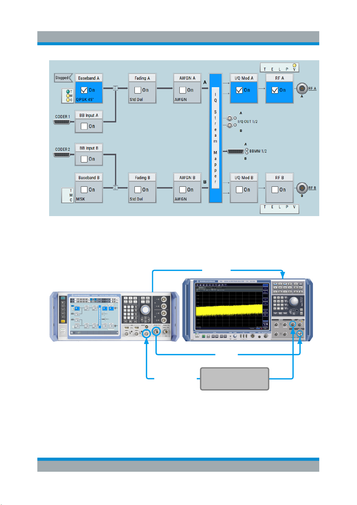
R&S®SMW200A
Trying Out the Instrument
Triggering the Instrument with an External Signal
To connect the instrument and the external trigger source
1. Use a suitable cable to connect the external trigger source to the USER 3
connector of the R&S SMW, see Figure 6-6.
REF OUT
(Rear Panel)
USER 3
RF A
Global Trigger 1
Reference
Signal
External Trigger Source
REF IN
INPUT
TRIGGER
RF
INPUT
Figure 6-6: Simplified representation of a test setup**
** = The figure depicts the cabling as a general principle; in a particular test setup not all
connections are required at the same time
58Getting Started 1412.9220.02 ─ 21
Page 59
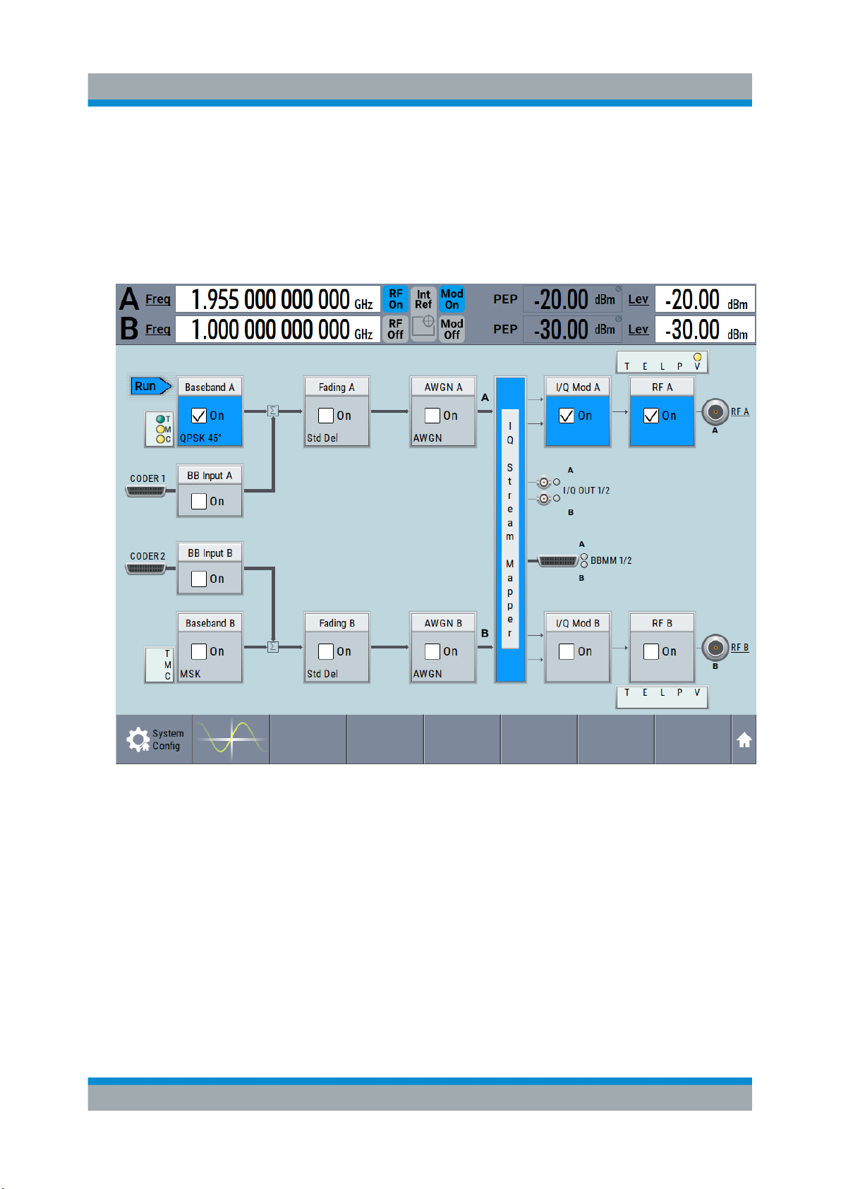
R&S®SMW200A
Triggering the Instrument with an External Signal
The Figure 6-6 depicts the location of the connectors and explains the connection as principle. In practice, you would rather "substitute" the analyzer by
a DUT, like a base station (BS). Other than in the example, the DUT can be
the source for the reference signal. Instead of using an external trigger
source, the DUT can also sends for example a frame trigger signal to the
R&S SMW. The R&S SMW acts still as the signal source.
Trying Out the Instrument
2. Use suitable cables to connect the RF A/B and REF OUT connectors of the
R&S SMW to the signal analyzer or the DUT.
Upon the receiving of an external trigger event, the R&S SMW starts the signal generation and then generates a continuous signal. An "Arm" stops the
signal generation. A subsequent trigger event causes a restart of the signal
generation.
59Getting Started 1412.9220.02 ─ 21
Page 60
R&S®SMW200A
To learn more about this topic, refer to:
●
Chapter "Local and Global Connectors" in the user manual
●
Chapter "Regular Trigger Signals" in the user manual
Enabling and Configuring a Marker Signal
Trying Out the Instrument
6.4 Enabling and Configuring a Marker Signal
Test setups often require that an external device is synchronized to the generated
data stream. For this purpose, the R&S SMW can output marker signals (or markers) additionally to the generated signal. The R&S SMW provides several regular
marker signals and marker signals specific to the firmware option. With suitable
marker settings for instance, you can mark slot or frame boundaries or mark the
start of a particular modulation symbol.
This example extends further the configurations performed in Chapter 6.2, "Gen-
erating a Digitally Modulated Signal", on page 51. We assume a default connector
mapping (see Figure 6-5).
In this example, we use the global USER connectors. Alternatively, you can
achieve the same configuration goal with the local T/M/C connectors.
This test setup requires one oscilloscope, like the R&S®RTO, as additional equipment.
1. In the block diagram, select "Block Diagram > Baseband > Misc > Custom
Digital Mod > Marker" tab.
2. Select "Marker Mode > Marker 1 > Pulse" and "Divider = 32".
Generated is a periodic marker with marker frequency of 120 KHz. The signal
is output at the USER 1 connector of the R&S SMW (see Figure 6-5).
3. Use a suitable cable to connect the USER 1 connector of the R&S SMW to
the monitoring instrument, for example oscilloscope like R&S®RTO, see Fig-
ure 6-7.
60Getting Started 1412.9220.02 ─ 21
Page 61
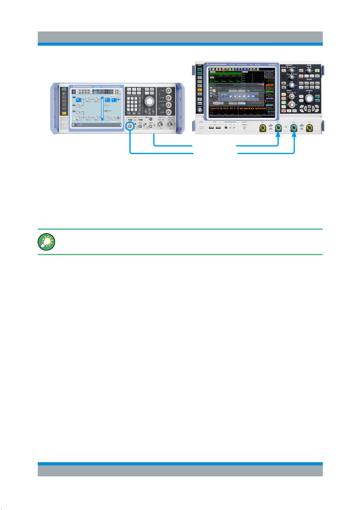
R&S®SMW200A
Trying Out the Instrument
Routing the Signal through the Instrument and Defining the Output Connectors
USER 1
Figure 6-7: Simplified representation of a test setup for signal monitoring**
** = The figure depicts the cabling as a general principle
I OUT
(Rear Panel)
Signal
Marker 1
4. Use a suitable cable to connect the I OUT connector of the R&S SMW to the
monitoring instrument.
To learn more about this topic, refer to chapter "Regular Marker Output Signals" in the user manual.
6.5 Routing the Signal through the Instrument and
Defining the Output Connectors
This section emphasizes on the signal routing capabilities in the default state of
the instrument (standard system configuration mode). The R&S SMW provides
the "I/Q Stream Mapper" function to route and distribute each of the generated
I/Q signals (streams) to any of the available output connectors.
In the provided example, you use the R&S SMW to generate two baseband signals, apply a baseband frequency shift, weight them and add them. You then
route the generated stream and define the output connector. The initial situation is
the configuration described in Chapter 6.3, "Triggering the Instrument with an
External Signal", on page 53.
The minimum requirement for the instrument in this example is an R&S SMW
equipped with the options 2xR&S SMW-B10, R&S SMW-B13T, and 2xR&S SMWB103.
61Getting Started 1412.9220.02 ─ 21
Page 62
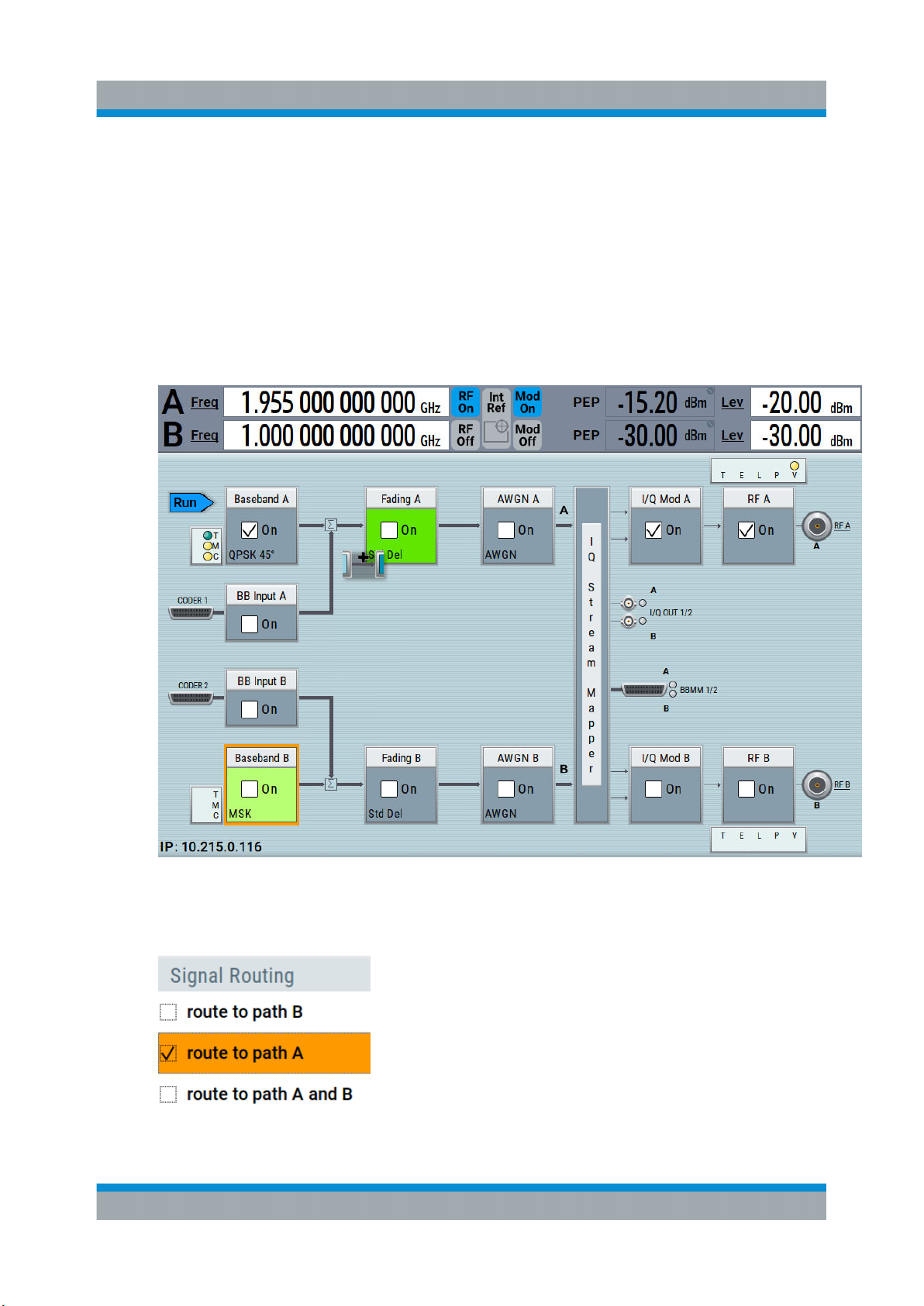
R&S®SMW200A
Routing the Signal through the Instrument and Defining the Output Connectors
To configure a composed baseband signal
1. In the first baseband, generate a WCDMA-3GPP signal as described in Chap-
ter 6.2, "Generating a Digitally Modulated Signal", on page 51.
2. To route the signal from "Baseband B" block to the first signal path, use one of
the alternatives:
● In the block diagram, select "Baseband B" block and drag&drop it to the
first path ("Fading A" block or "AWGN A" block depending on the options
installed on your instrument).
Trying Out the Instrument
Select the "Fading B" block and drag&drop it to the "Baseband B" block.
● In the block diagram, select "Baseband B" block, navigate in the context
menu, and select "Signal Routing > route to path A".
The block diagram displays the routing.
62Getting Started 1412.9220.02 ─ 21
Page 63
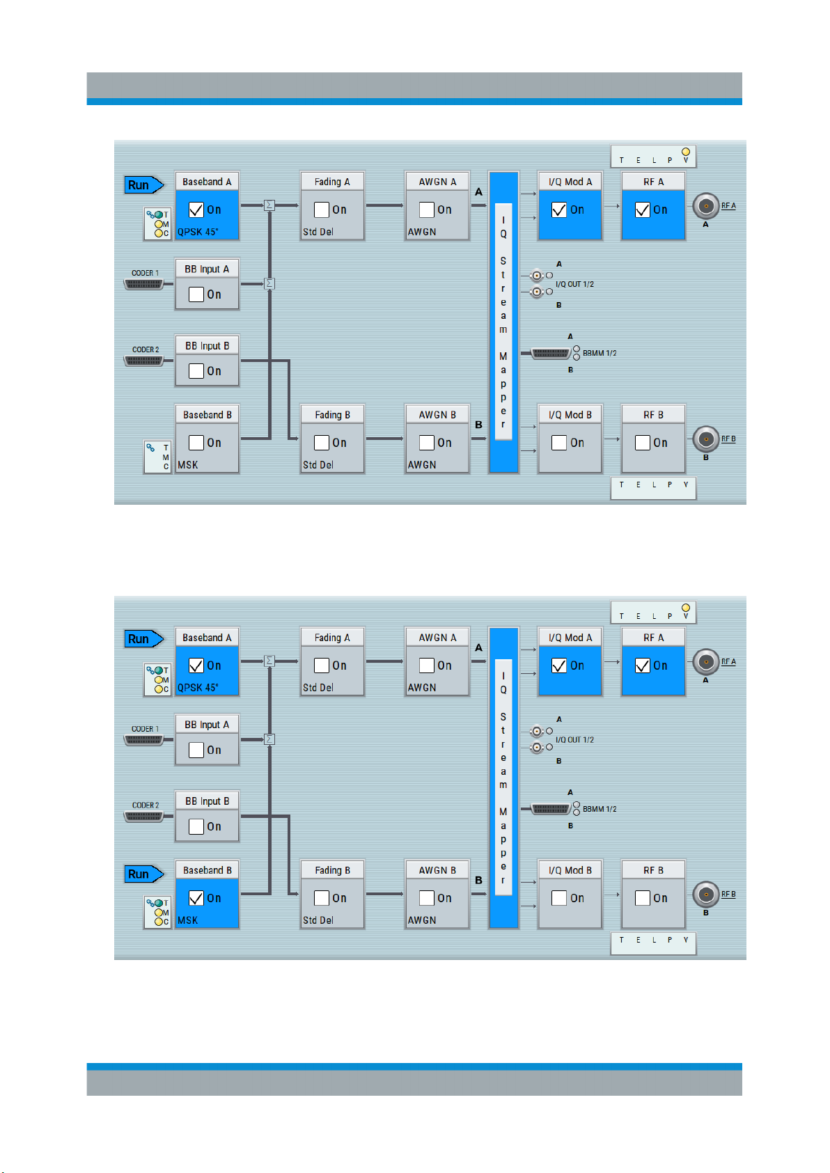
R&S®SMW200A
Routing the Signal through the Instrument and Defining the Output Connectors
Trying Out the Instrument
3. In the block diagram, select "Baseband B > Misc > Custom Digital Mod...",
select "Set acc. to standard > 3GPP FDD" and enable "Custom Digital Modulation > State > On".
4. To apply frequency and power offsets to the signals, select "Baseband B >
Baseband Offsets".
a) Enter "Baseband A > Frequency Offset > 5 MHz".
63Getting Started 1412.9220.02 ─ 21
Page 64
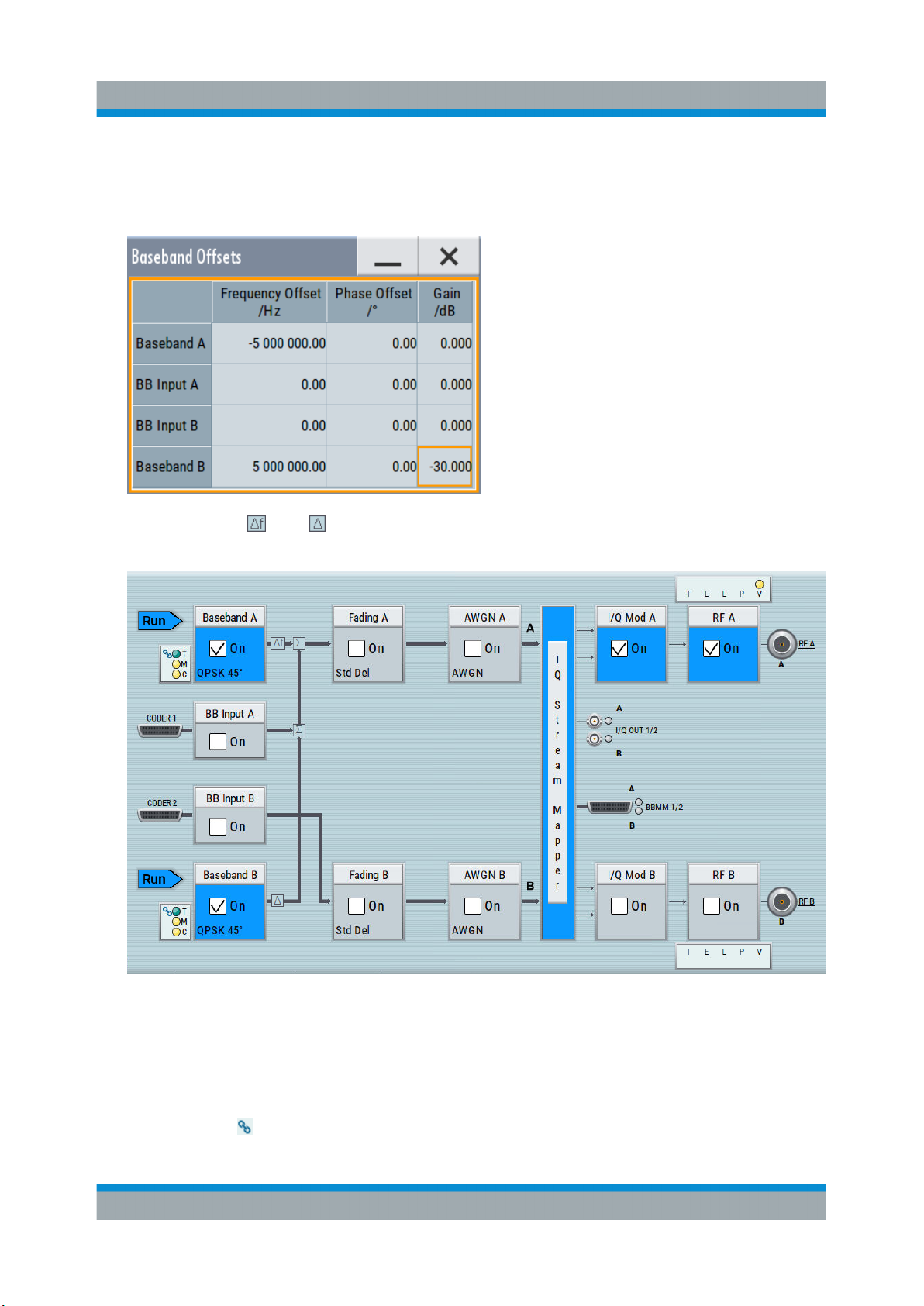
R&S®SMW200A
Trying Out the Instrument
Routing the Signal through the Instrument and Defining the Output Connectors
b) Enter "Baseband B > Frequency Offset > -5 MHz".
c) Enter "Baseband B > Path Gain > -30 dB".
d) Close the "Baseband Offsets" dialog.
The symbols and in the block diagram confirm that the signals are added
weighted with a frequency offset on both paths and a path gain on path B.
Figure 6-8: Block diagram: Generating a composed signal (stream A)
To enable simultaneous signal generation in both basebands, the R&S SMW
couples the trigger settings in the available basebands. The trigger settings
enabled in "Baseband A" apply automatically to the "Baseband B".
The symbol confirms that common trigger settings are applied.
64Getting Started 1412.9220.02 ─ 21
Page 65
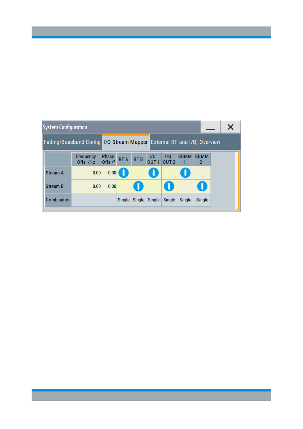
R&S®SMW200A
Routing the Signal through the Instrument and Defining the Output Connectors
To map the I/Q stream and define the output connector
The term stream describes the signal at the input of the "I/Q Stream Mapper" up
to the output connectors of the instrument.
1. In the block diagram, select the "I/Q Stream Mapper" block.
The "System Configuration > I/Q Stream Mapper" dialog displays the current
(default) distribution and mapping of the I/Q streams to the output connectors
as a mapping matrix.
Trying Out the Instrument
Stream A is routed to all the available output connectors: the analog RF A and
I/Q ("I/Q OUT 1") connectors, and the digital I/Q output connectors DIG I/Q
("BBMM1").
2. To reconfigure the mapping, tap a matrix entry, for example disable the output
of stream A on the BBMM 1 interface.
With the "I/Q Stream Mapper", you route the streams; the outputs are, however, not necessarily activated.
Tip: How to access the settings of the input and output interfaces.
In the block diagram, the blocks related to the input and output interfaces can
be folded for a better overview.
If the block diagram does not show the "I/Q Analog" block, tap the corresponding connector icon, i.e. "I/Q Out 1/2", to unfold the settings.
65Getting Started 1412.9220.02 ─ 21
Page 66
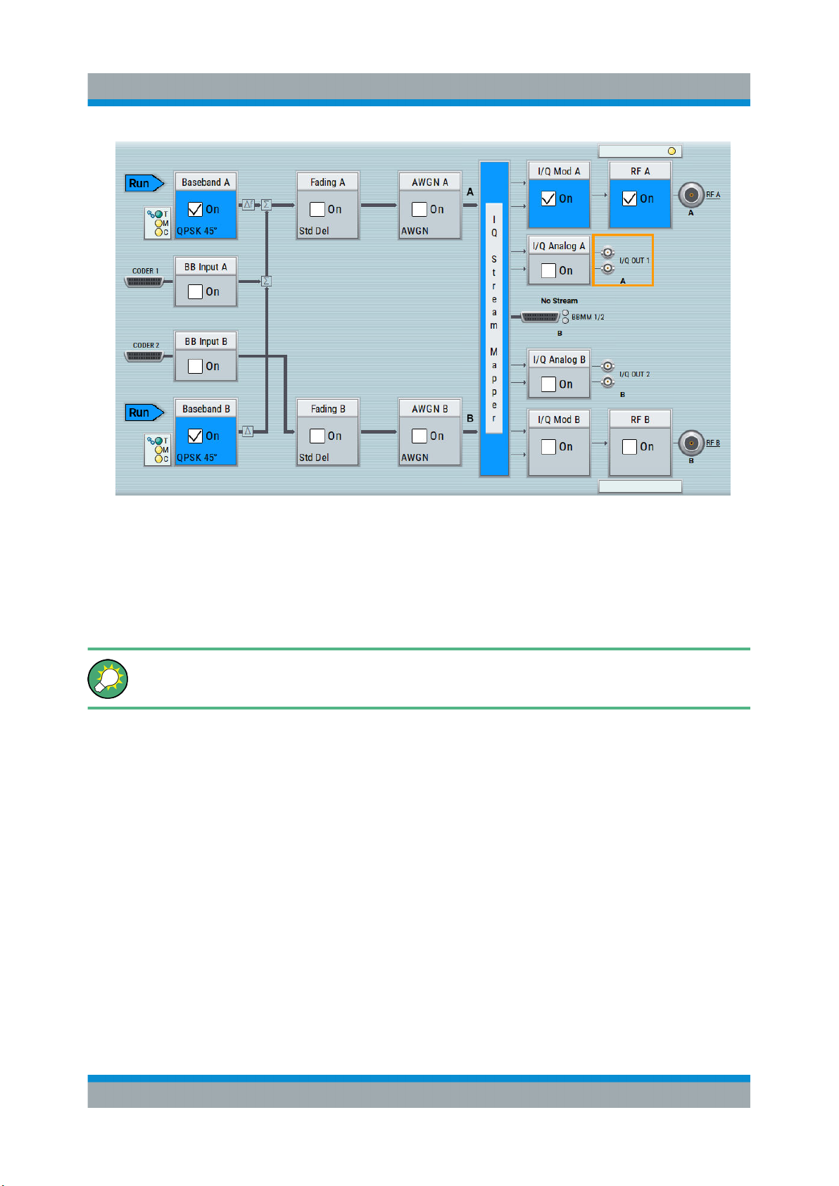
R&S®SMW200A
Trying Out the Instrument
Verifying the Generated Signal with the Graphics Display
The generated composed signal (stream A) is output at the analog RF A connector and routed to the I/Q Out 1 connector. The block diagram confirms this
routing and displays the letter "A" next to the symbols of the output connectors.
Consider however that the I/Q connectors are disabled.
To learn more and to explore the whole range of the routing capability, refer
to chapter "Signal Routing and System Configuration" in the user manual.
6.6 Verifying the Generated Signal with the Graph-
ics Display
It is often useful to check the spectra of the configured signals, before you enable
the RF output of the instrument.
The R&S SMW provides a build-in function to represent the generated signal on a
graphical signal display. We demonstrate this feature by showing the characteristics at one particular point of the signal processing chain. You can, however, display the signal characteristics at other different stages.
66Getting Started 1412.9220.02 ─ 21
Page 67
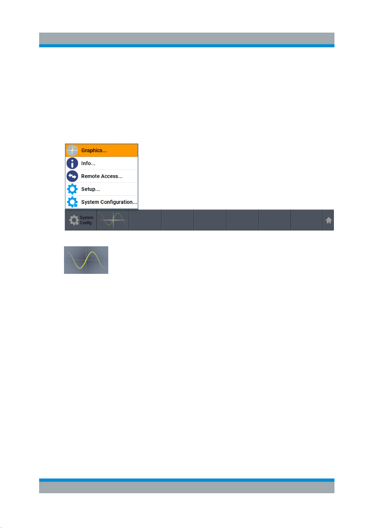
R&S®SMW200A
Verifying the Generated Signal with the Graphics Display
This example shows you how to use this graphical display to verify the generated
signal. Use the signal generated in Chapter 6.5, "Routing the Signal through the
Instrument and Defining the Output Connectors", on page 61.
To access the graphical signal display functionality
► Perform one of the following:
a) Select "Taskbar > System Configuration > Graphics"
Trying Out the Instrument
b) On the "Taskbar", tap the wave icon.
The "Graphics Configuration" dialog opens.
To visualize the sum signal
1. In the "Graphics Configuration" dialog, select "Mode > Power Spectrum".
2. Select "Source > A Stream".
3. Select "Add" to enable signal display.
67Getting Started 1412.9220.02 ─ 21
Page 68
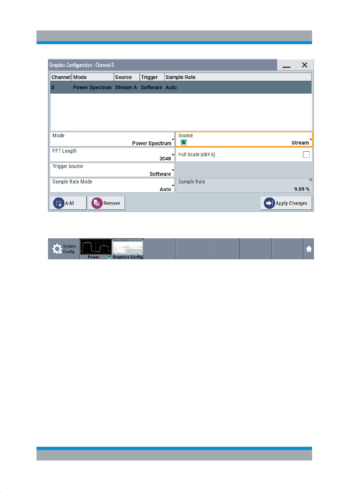
R&S®SMW200A
Trying Out the Instrument
Verifying the Generated Signal with the Graphics Display
A new thumbnail (minimized view) indicating the active diagram appears in
the "Taskbar".
4. Press the thumbnail graphic.
The graphic enlarges and the diagram is displayed in a normal size
68Getting Started 1412.9220.02 ─ 21
Page 69
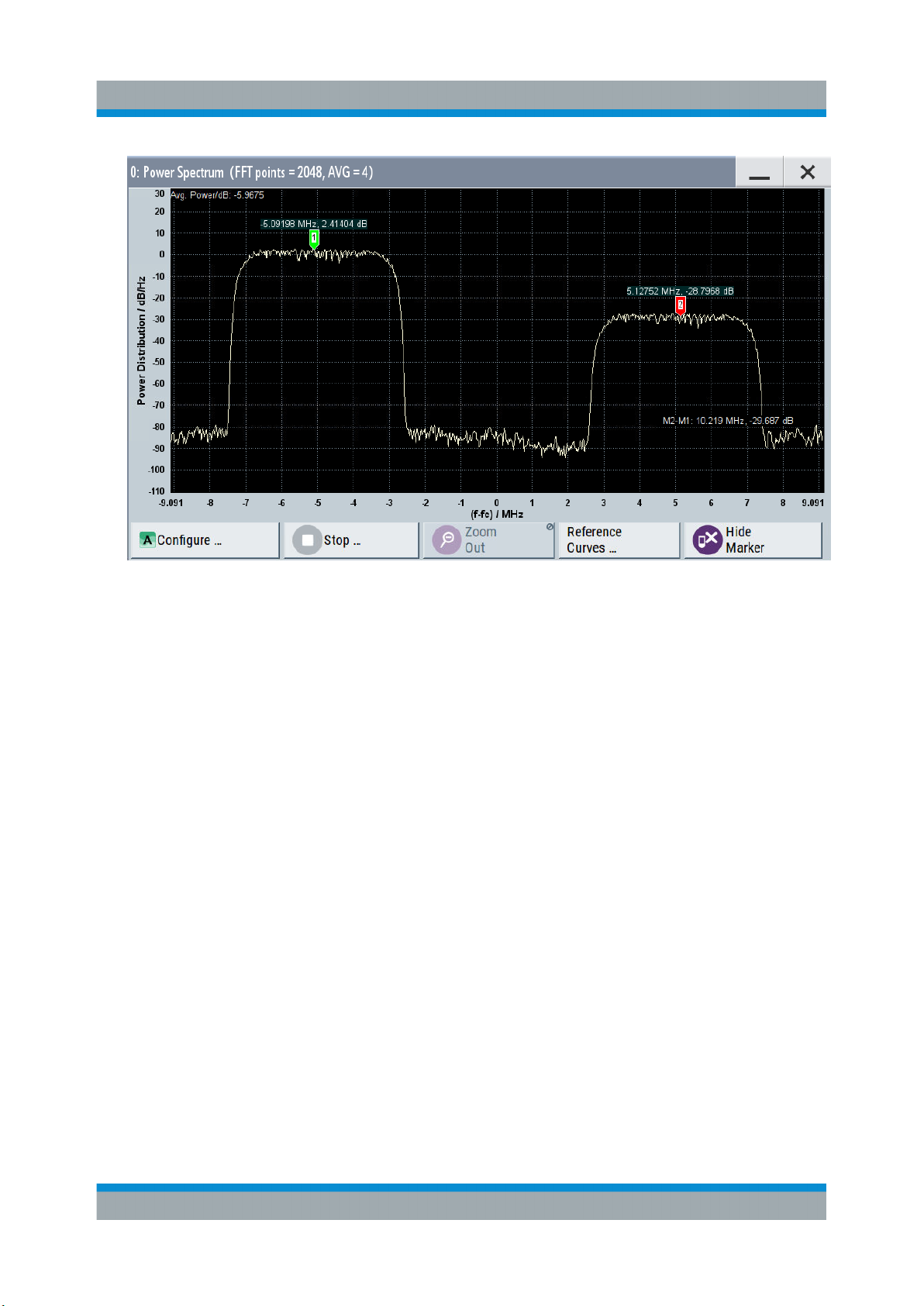
R&S®SMW200A
Trying Out the Instrument
Verifying the Generated Signal with the Graphics Display
The "Power Spectrum" displays two signals, both 3GPP FDD signals are frequency shifted and the right one is also attenuated.
5. To retrieve more information, zoom in the spectrum and select "Show Marker"
to measure the distance between the two signals.
In principle, the zoom in function works like the two-finger pinching for magnifying images on your cell phone.
6. In the "Power Spectrum" dialog, select "Configure" to return to the "Graphics
Configuration" dialog.
Close the "Graphics Configuration" dialog.
This action has no effect on the configured graphics but on the dialog itself.
The block diagram displays the current signal routing. It indicates that frequency and power offsets are enabled and displays the acquisition points for
the real-time diagrams minimized in the "Taskbar".
69Getting Started 1412.9220.02 ─ 21
Page 70
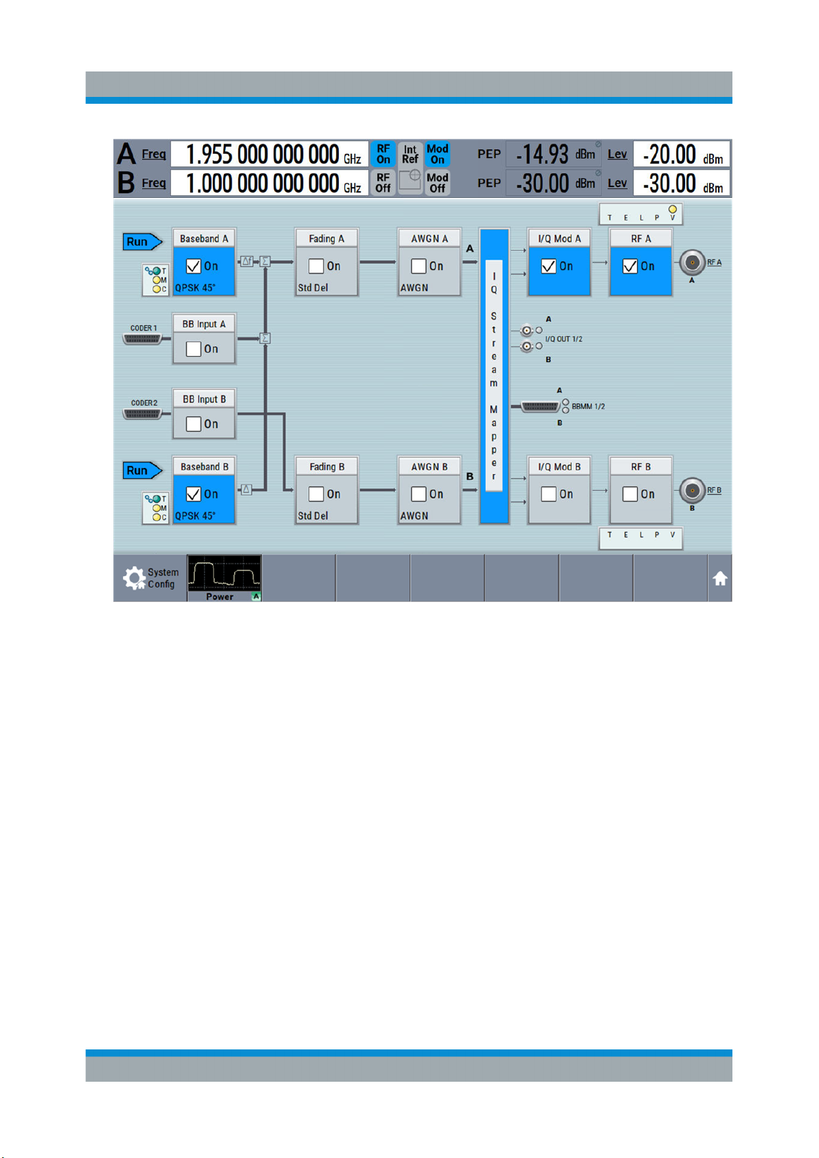
R&S®SMW200A
Trying Out the Instrument
Saving and Recalling Settings
6.7 Saving and Recalling Settings
To restore the results of our measurements later, we saved the instrument settings to a file.
To save the instrument settings to a file
We assume, a test configuration as described in Chapter 6.5, "Routing the Signal
through the Instrument and Defining the Output Connectors", on page 61.
1. Press the [SAVE/RCL] key on the front panel.
2. In the "Save/Recall" dialog box, select "Operation Mode > Save".
Tap the "Filename", use the on-screen keyboard, and enter MyTestSignal.
70Getting Started 1412.9220.02 ─ 21
Page 71
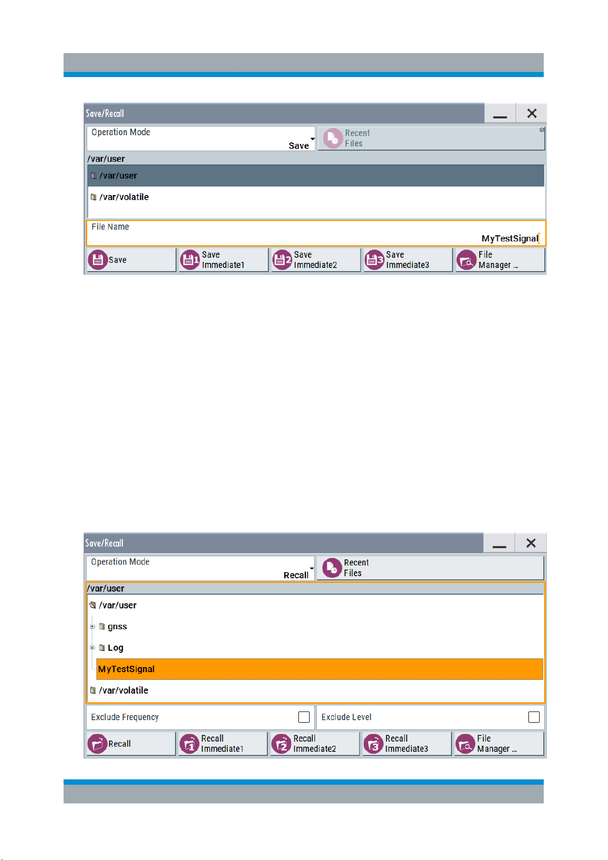
R&S®SMW200A
3. Tap the "Save" button.
The file MyTestSignal.savrcltxt is saved in the default directory /var/
user.
Trying Out the Instrument
Saving and Recalling Settings
To load saved instrument settings
You can restore the settings to the instrument at any time using the settings file.
1. Press the [PRESET] button to restore the default instrument settings so you
can check that the saved user settings are restored afterwards.
2. Press the [SAVE/RCL] key.
3. In the "Save/Recall" dialog, select "Recall" operation.
Navigate to the directory the file is saved in and select the MyTestSignal
file.
71Getting Started 1412.9220.02 ─ 21
Page 72
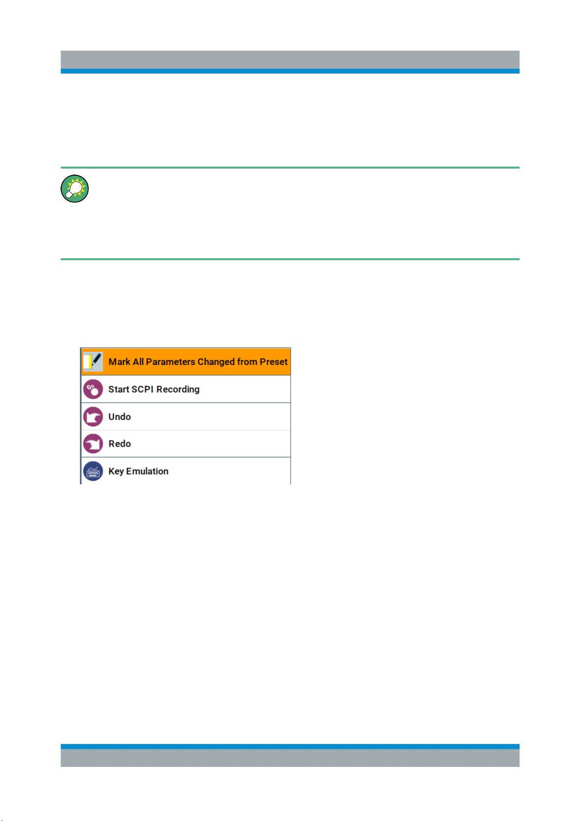
R&S®SMW200A
4. Tap the "Recall" button.
All instrument settings are restored and the display resembles Figure 6-8,
which shows the instrument display right before the settings were saved.
How to display all parameters with values different to their preset values
When you load a file to your instrument, you may do not have enough information on the changed settings. In such case, it is useful to visualize all
parameters that have been changed from their default state.
Try out the following:
●
Tap and hold on an empty space in the block diagram to access the contextsensitive menu.
●
Select "Mark all parameters changed from preset".
Trying Out the Instrument
Saving and Recalling Settings
●
All changed parameters are highlighted.
72Getting Started 1412.9220.02 ─ 21
Page 73
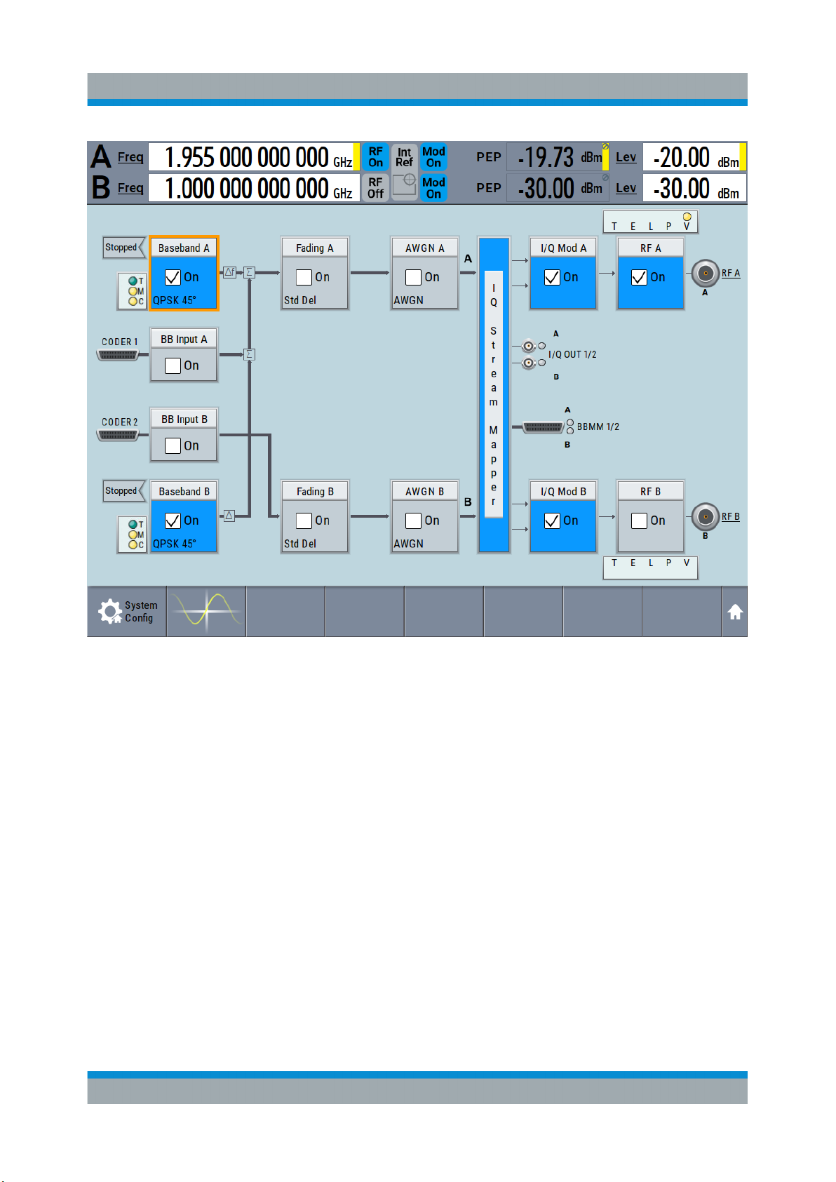
R&S®SMW200A
Trying Out the Instrument
Generating an EUTRA/LTE Signal
6.8 Generating an EUTRA/LTE Signal
The main application field of the R&S SMW is the generation of digital signals in
accordance with several telecommunication and wireless standards, like
WCDMA, EUTRA/LTE or WLAN, to name a few. This example uses the digital
standard EUTRA/LTE to introduce the way you can access and interact with the
instrument and experience the advantages provided by the additional options.
The minimum requirement for R&S SMW in this example is a base unit equipped
with the additional option R&S SMW-K55 EUTRA/LTE.
73Getting Started 1412.9220.02 ─ 21
Page 74
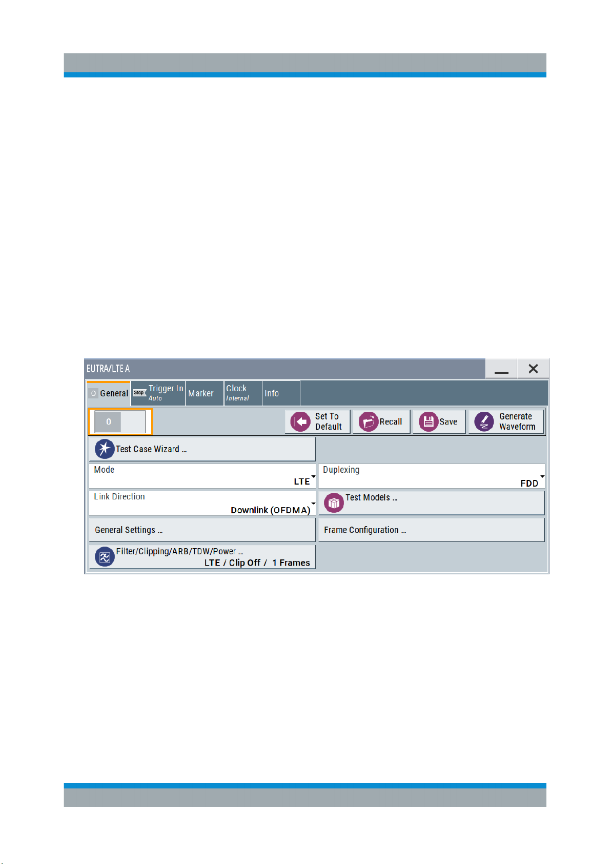
R&S®SMW200A
Generating an EUTRA/LTE Signal
To generate a downlink test signal
The main focus of the following example is not on the R&S SMW capabilities and
the features provided by the firmware option. The example aims rather to help
you get familiar with the settings and configuration principle common for the digital standards.
We use one of the provided EUTRA test models (E-TM) to show how to generate
a test signal upon a quick selection.
1. On the R&S SMW front panel, press the [PRESET] key to start out in a
defined instrument configuration.
2. In the block diagram, select "Baseband > Beyond 3G Standards > EUTRA/
LTE".
The EUTRA/LTE dialog appears and displays the general settings provided for
the digital standard.
Trying Out the Instrument
As in the user interfaces of all digital standards, the "EUTRA/LTE" dialog is
divided into several tabs. The "General" tab comprises the primary settings of
the standard, the functions for storing and recalling settings and provides
access to further functions and dialogs, like the "Filter" settings. The "Trigger
In", "Marker" and "Clock" tabs comprise the settings related to the corresponding function.
The more complex the digital standard itself is, the more comprehensive the
further dialog and tab structure. The start dialog of each digital standard, however, follows a repeating dialog structure that comprises the tabs "General",
"Trigger In", "Marker" and "Clock". (See also Chapter 8.3.4, "Additional Dis-
play Characteristics", on page 103).
74Getting Started 1412.9220.02 ─ 21
Page 75
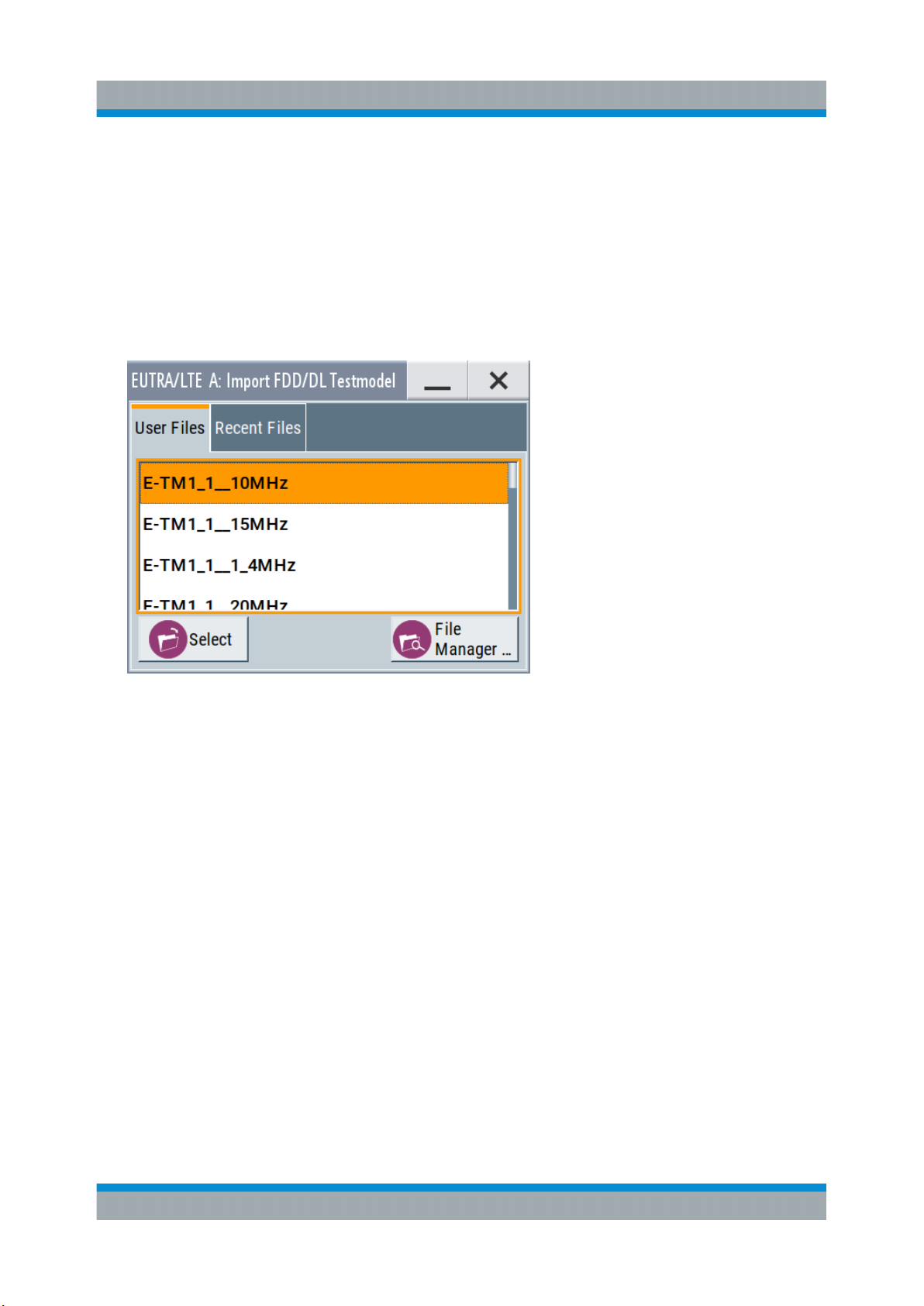
R&S®SMW200A
Generating an EUTRA/LTE Signal
Tip: To display the dialog in its maximal height, press the [RESIZE WINDOW]
key on the front panel.
3. In the "EUTRA/LTE General" tab, select "Test Models".
The test models is a function for quick selection and settings adjustment
according to one of the various EUTRA test models (E-TM).
A standard "File Select" function enables you to select form files with predefined settings.
Trying Out the Instrument
Tip: On the front panel, press the [HELP] key to retrieve detailed information
on the current settings and on the contents of the predefined files.
4. Navigate to a file, for example to the E-TM1_1__10MHz (an E-TM1.1 test
model with 10 MHz channel bandwidth) and confirm with "Select".
The dialog closes automatically and the user interface confirms the name of
the selected file.
5. In the "EUTRA/LTE > General" tab, select "State > On".
75Getting Started 1412.9220.02 ─ 21
Page 76
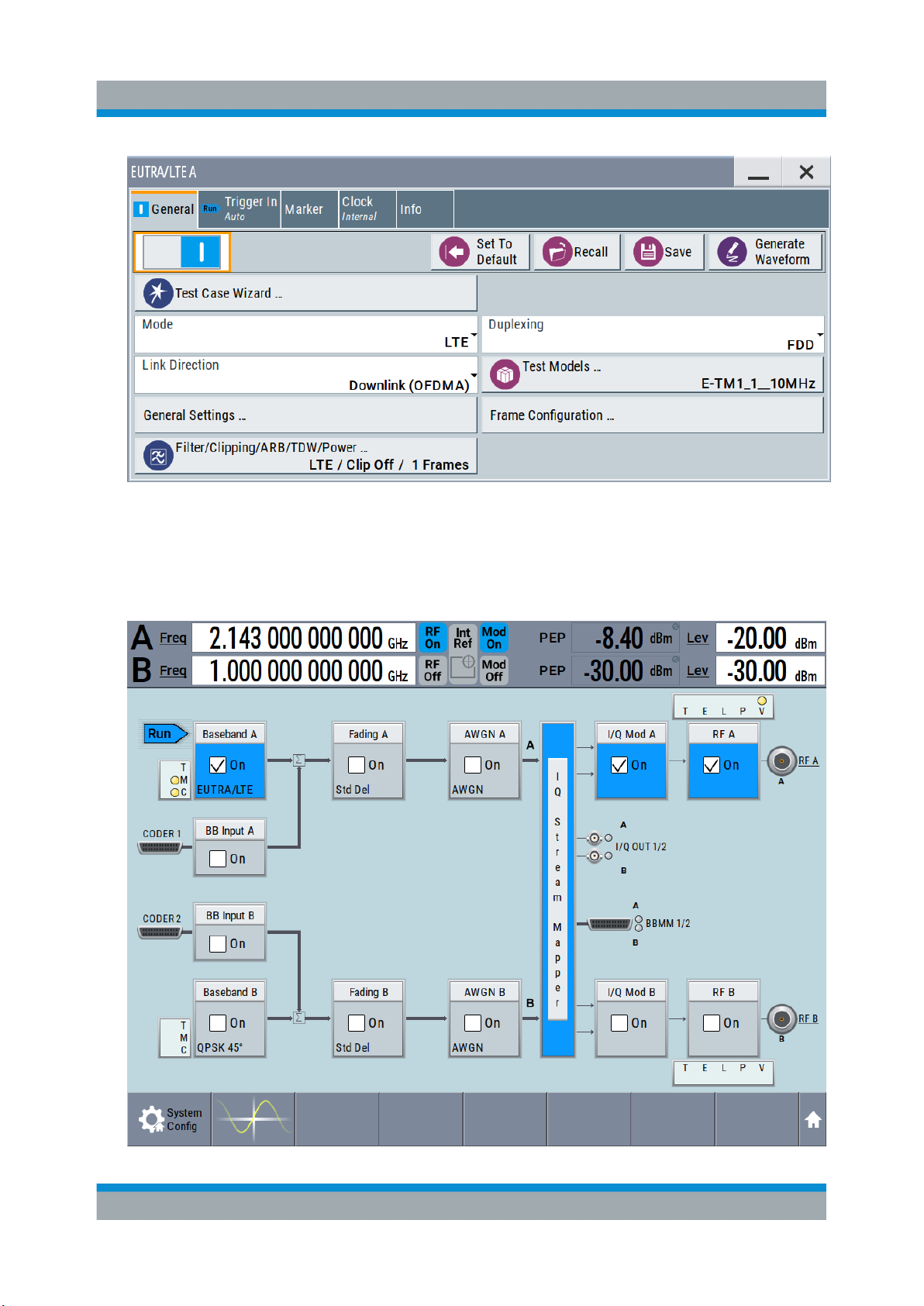
R&S®SMW200A
Generating an EUTRA/LTE Signal
Close the dialog.
6. On the "Status Bar", tap the "Freq" and "Lev" fields and enter new values, for
example 2.143 GHz and -20 dBm.
Select "RF A > On".
Trying Out the Instrument
76Getting Started 1412.9220.02 ─ 21
Page 77
R&S®SMW200A
Using the System Configuration Capabilities for MIMO Setups
The instrument generates an EUTRA/LTE test signal with the selected channel bandwidth, frequency, and level.
With these first steps, you have gained an impression of the provided functionality.
For a comprehensive description of the full range of capabilities, refer to the
user manual "EUTRA/LTE Digital Standard for R&S SMW200A".
Trying Out the Instrument
6.9 Using the System Configuration Capabilities for
MIMO Setups
The R&S SMW supports versatile MIMO configurations and provides comfortable
functions to simplify the definition and signal routing for MIMO test setups and
configuration involving several instruments. For complex routing scenarios, the
"System Configuration" functionality is the start and central configuration point.
Within one dialog, you can configure complex configurations with up to 8 Tx or Rx
antennas or up to two stand-alone 2x2 MIMO systems, e.g. 8x2 MIMO or LTE-A
carrier aggregation with 2x2 MIMO.
This example does not cover the whole range of the "System Configuration"
capabilities but delivers an insight into the topic. The example shows how to use
coupled baseband sources and select a suitable fading and baseband configuration to generate an EUTRA/LTE signal in 2x2 MIMO configuration.
To learn more and to explore the whole range of capability provided by the
"System Configuration" function, refer to chapter "Signal Routing and System Configuration" in the user manual.
The instrument in this example is a R&S SMW equipped with two signal paths:
●
2 options standard baseband generator R&S SMW-B10 and one R&S SMWB13T
●
2 options fading simulator R&S SMW-B14 and one option fading MIMO
R&S SMW-K74
●
Frequency options R&S SMW-B10x/-B20x
●
2 options R&S SMW-K55 EUTRA/LTE
77Getting Started 1412.9220.02 ─ 21
Page 78
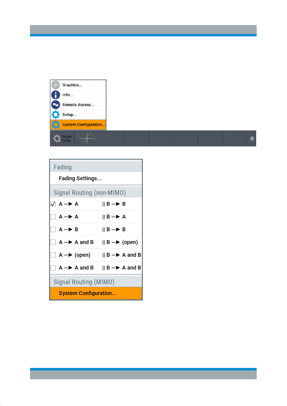
R&S®SMW200A
Using the System Configuration Capabilities for MIMO Setups
To access the "System Configuration" function
1. Perform one of the following:
a) On the "Taskbar", select "System Config > System Configuration"
b) In the block diagram, select "Fading > MIMO > System Configuration"
Trying Out the Instrument
c) In the block diagram, select "I/Q Stream Mapper" and select the "Fading/
Baseband Configuration" tab.
The "System Configuration > Fading/Baseband Configuration" dialog displays
the current signal routing. The instrument works in the default "Standard"
mode.
78Getting Started 1412.9220.02 ─ 21
Page 79
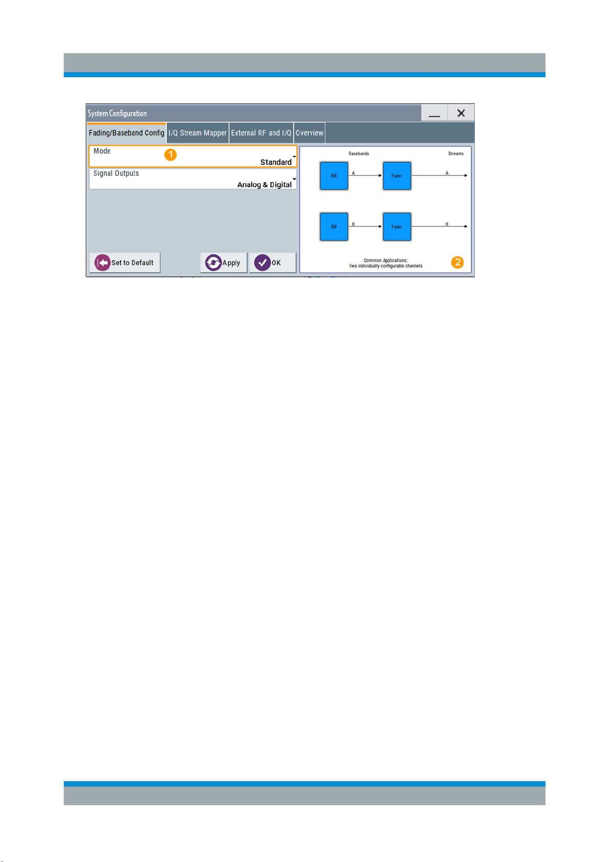
R&S®SMW200A
Trying Out the Instrument
Using the System Configuration Capabilities for MIMO Setups
Figure 6-9: System Configuration in the default Standard Mode
1 = Standard or advanced mode; the last is required for configuration of complex LxMxN
MIMO scenarios
2 = Simplified preview diagram with a description of the common application for the particu-
lar configuration
2. Open "System Configuration > I/Q Stream Mapper" to obtain an overview of
the current distribution and mapping of the I/Q streams to the output connectors, see also "To map the I/Q stream and define the output connector"
on page 65.
3. Open "System Configuration > External RF and I/Q Instruments" to gain information on the current setup.
The tab comprises the additional settings provided to simplify the configuration of connected instruments, like configuring the connectors, establishing a
connection to the instruments, or controlling these instruments.
In this test setup, no further instruments are connected.
To enable a 2x2 MIMO configuration (1x2x2 "Fading and Baseband Configuration")
1. In the "System Configuration > Fading/Baseband Configuration" dialog, select
"Mode > Advanced" and enable the following settings:
a) "Entities (Users, Cells) > 1", "Basebands (Tx Antennas) > 2", "Streams (Rx
Antennas) > 2"
b) Select "BB Source Config > Coupled Sources"
c) Observe the signal routing displayed on the preview diagram. Does it
match with the expected signal routing?
d) Select "Apply" to confirm the configuration.
79Getting Started 1412.9220.02 ─ 21
Page 80
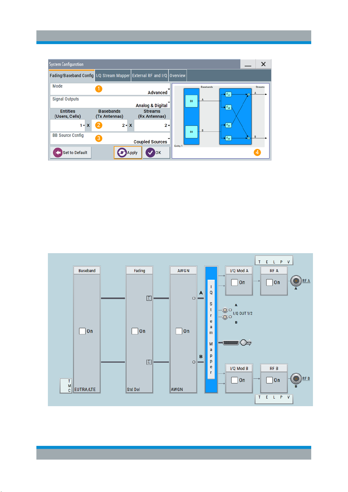
R&S®SMW200A
Trying Out the Instrument
Using the System Configuration Capabilities for MIMO Setups
Figure 6-10: System Configuration in the Advanced Mode (1x2x2 configuration)
1 = Advanced mode, required for configuration of complex LxMxN MIMO scenarios
2 = Current signal routing; 2x2 MIMO configuration
3 = Separated and coupled baseband sources
4 = Simplified preview diagram of the particular configuration
2. Leave all further settings, i.e. the "I/Q Stream Mapper" settings, at their default
values and close the "System Configuration" dialog.
The block diagram displays the selected configuration.
80Getting Started 1412.9220.02 ─ 21
Page 81
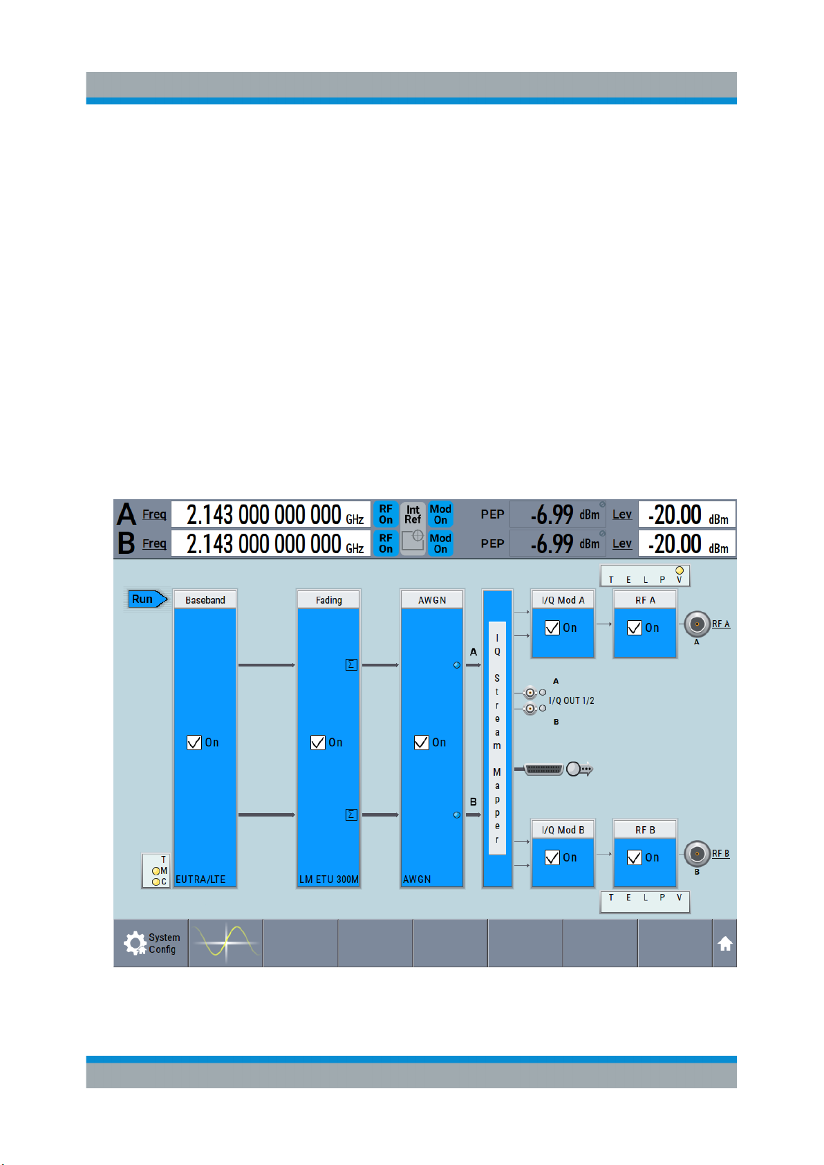
R&S®SMW200A
Using the System Configuration Capabilities for MIMO Setups
To generate an EUTRA/LTE signal in the 2x2 MIMO scenario
1. In the block diagram, select "Baseband > EUTRA/LTE", select "State > On",
and close the dialog.
In coupled baseband source mode, the R&S SMW takes over the baseband
signal configuration. The instrument adjusts the settings in the basebands
automatically, for example the mapping of the transmitting antennas to the
basebands.
2. In the block diagram, select "Fading > On".
The default "Standard Delay" fading profile is applied.
3. On the "Status Bar", set the same frequency and level settings for both paths:
a) "A Freq = B Freq = 2.143 GHz"
b) "Lev (A) = Lev (B) = -20 dBm"
4. In the block diagram, select "RF A > On" and "RF B > On".
Trying Out the Instrument
The R&S SMW generates a realistic EUTRA/LTE downlink signal with 10 MHz
channel bandwidth, though without any scheduled data.
81Getting Started 1412.9220.02 ─ 21
Page 82
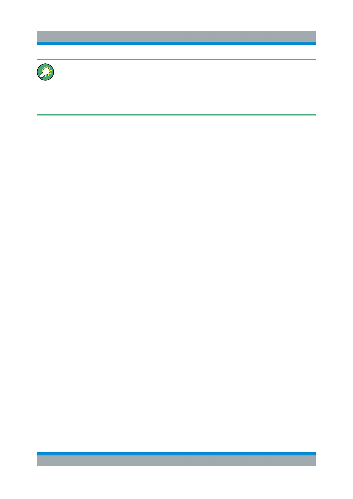
R&S®SMW200A
Using the System Configuration Capabilities for MIMO Setups
To enable the generation of scheduled data, further configurations are
required; these configurations are, however, outside the scope of this
description.
For further information, refer to the user manual "EUTRA/LTE Digital Standard for R&S SMW".
Trying Out the Instrument
82Getting Started 1412.9220.02 ─ 21
Page 83
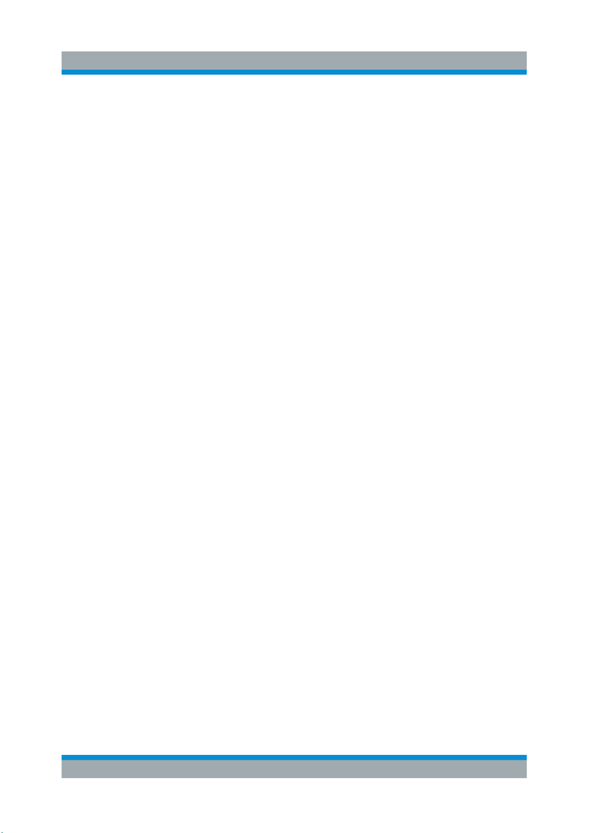
R&S®SMW200A
Brief Introduction to the Instrument's Concept
System Overview
7 System Overview
This section helps you to get familiar with the R&S SMW. It provides an introduction to the general concept of the instrument with a sample of the possible application fields. This section also introduces the main blocks in the signal generation
flow.
For information on how to access functions and interact with the R&S SMW, refer
to Chapter 8, "Instrument Control", on page 97.
7.1 Brief Introduction to the Instrument's Concept
The R&S SMW combines up to two independent signal generators in one instrument and offers unrivaled RF and baseband characteristics. Due to its modular
design, the instrument can be optimally adapted to the requirements of different
applications. Both RF paths can be equipped with one of the available frequency
options with different upper frequency limit. The baseband section of the
R&S SMW is fully digital. It contains the hardware for generating and processing
I/Q signals in realtime or generating signals with an arbitrary waveform generator.
7.1.1 The Signal Flow at a Glance
The R&S SMW is equipped with a large touchscreen, that displays a block diagram. The block diagram represents the signal flow and the general stages the
signal generation goes through. Depending on the options the R&S SMW is
equipped with, the appearance of the block diagram changes.
The following examples do not cover all possible cases but aim to introduce the
way the block diagram depicts the installed options.
●
An example of a base unit, equipped with one signal path (R&S SMW-B10,
R&S SMW-B13, and R&S SMW-B103/-B106)
83Getting Started 1412.9220.02 ─ 21
Page 84
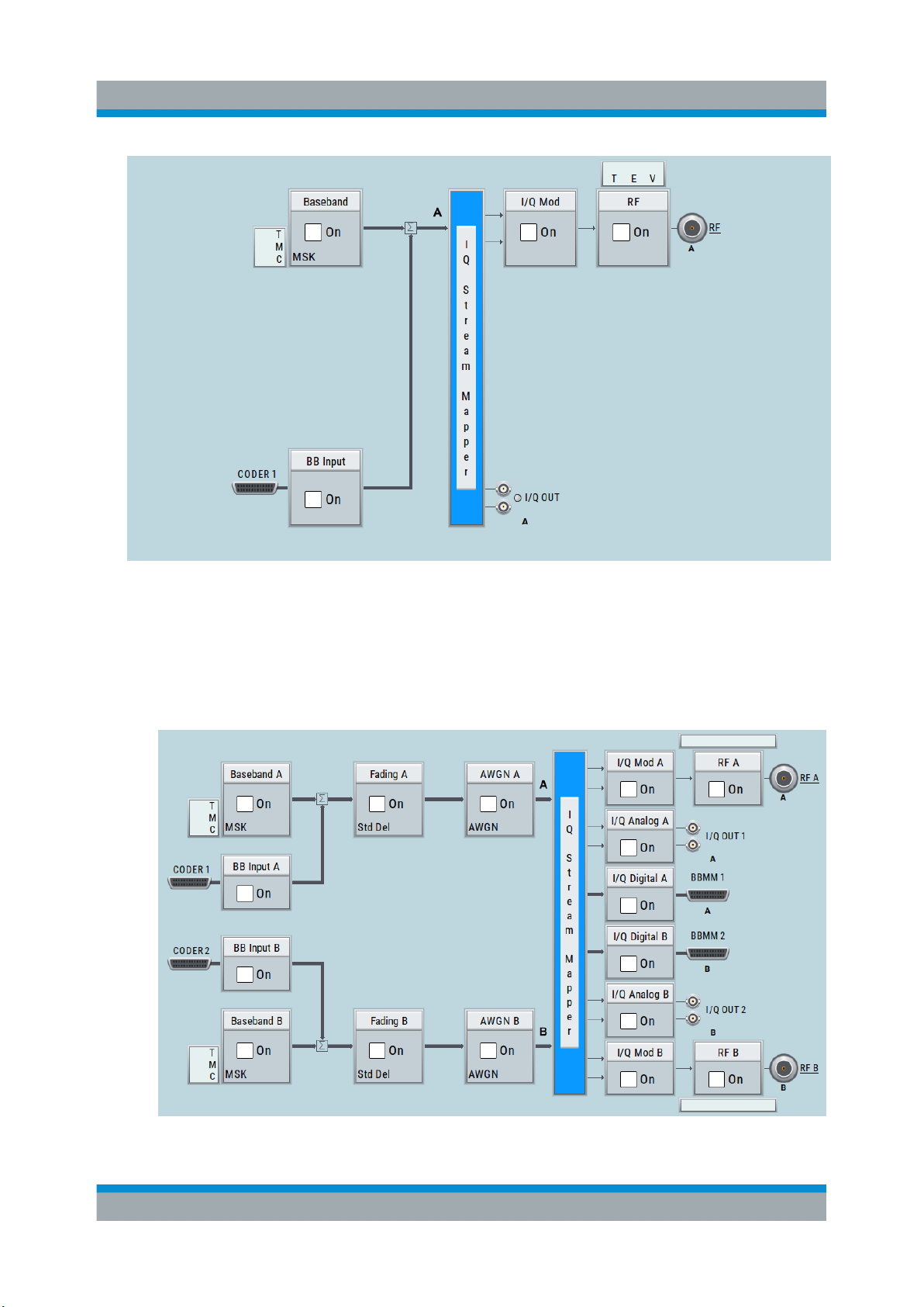
R&S®SMW200A
System Overview
Brief Introduction to the Instrument's Concept
●
Two examples of a fully equipped (standard baseband) instrument.
The first one shows the default instrument state and the second one - an
advanced configuration with more abstract representation.
– In this "classic" representation, the block diagram displays all blocks for
that the required hardware and software options are fitted. The block diagram shows the signal flow as it is.
Figure 7-1: Block diagram of a fully equipped two path instrument (default)
84Getting Started 1412.9220.02 ─ 21
Page 85
R&S®SMW200A
System Overview
Brief Introduction to the Instrument's Concept
– The block diagram depicting a 4x4 MIMO scenario with coupled baseband
sources is a more abstract representation. Each stage of the signal generation is still represented by a functional block but the signal routing is displayed in a conceptional manner.
Figure 7-2: Block diagram of a fully equipped two path instrument (4x4 MIMO con-
figuration)
For more examples, see also Chapter 7.2, "Applications Examples of the
R&S SMW", on page 90.
The cross-reference between the installed options and the displayed settings
The Table 7-1 is an excerpt of the available options and lists only the options
required to display a functional block in the block diagram. The information
assumes R&S SMW equipped with standard baseband generator R&S SMW-B10
and R&S SMW-B13T.
For exact information on the available options, and on the minimum requirements
and the interdependencies between the provided options, refer to the R&S SMW
data sheet.
85Getting Started 1412.9220.02 ─ 21
Page 86
R&S®SMW200A
System Overview
Brief Introduction to the Instrument's Concept
Table 7-1: Required options per functional block (excerpt)
Functional block Required option
"Baseband A" R&S SMW-B10
"Baseband B" Second option R&S SMW-B10
"BB Input A" Included in R&S SMW-B10
"BB Input B" Included in second option R&S SMW-B10
"Fading A" R&S SMW-B14
"Fading B" Second option R&S SMW-B14
"AWGN A"/"AWGN B" At least one option R&S SMW-K62
"I/Q Stream Mapper" -
"I/Q Mod A" R&S SMW-B103/-B106
"I/Q Mod B" R&S SMW-B203/-B206
"I/Q Analog A" R&S SMW-B13
"I/Q Analog B" R&S SMW-B13T
"I/Q Digital A" R&S SMW-K18
"I/Q Digital B" Second option R&S SMW-K18
"RF A" R&S SMW-B103/-B106
"RF B" R&S SMW-B203/-B206
7.1.2 Internal Baseband Source ("Baseband" Blocks)
The "Baseband" block represents the source of the baseband signals (basebands).
This functional block is the access point to:
●
The internal baseband generator
The baseband generator contains modules for real time signal generation
(Custom Digital Modulation) and an arbitrary waveform generator (ARB).
One or two baseband generators can be fitted in an R&S SMW and operated
separately.
●
The available digital standards
Generation of digital signals in accordance with the supported standards
requires additional software options. For example, option R&S SMW-K55 generates signals according to the EUTRA/LTE standard.
86Getting Started 1412.9220.02 ─ 21
Page 87
R&S®SMW200A
Brief Introduction to the Instrument's Concept
●
The signal routing (in the standard "classic" mode of a standard baseband
generator)
Signals from the baseband generators can be routed between the available
paths, and added (possibly with frequency, phase and power offsets).
System Overview
7.1.3 Digital Baseband Input and Output ("BB Input" and "I/Q
Digital" Blocks)
The "BB Input" and the "I/Q Digital" blocks are the access point to the settings of
the digital interfaces.
The R&S SMW is - depending on SW and HW options - able to receive digital
baseband signals and to output digital baseband signals. A fully equipped standard baseband instrument provides eight configurable digital interfaces. Depending on the configuration, the available digital interfaces may be used as up to six
inputs or up to six outputs.
The digital baseband inputs and outputs can be used together with other
Rohde&Schwarz instruments, like signal generators, signal analyzers, the digital
interface module R&S®EX-IQ-BOX, or the R&S®CMW500 Radio Communication
Tester. A Rohde&Schwarz signal generator for instance may serve as digital signal source in test configuration requiring more than two baseband sources. A test
setup with the R&S®CMW500 Radio Communication Tester is suitable for testing
under fading conditions.
The "BB Input" block is the access point to the settings of:
●
The external digital I/Q signals
The external digital I/Q signals are further processed in the baseband section
(e.g. fading, addition of noise)
●
The signal routing (in the standard "classic" mode)
The external and internal baseband signals can be routed and added (possibly with frequency, phase and power offsets).
The "I/Q Digital" block is the access point to the settings of:
●
The digital I/Q output signals
●
The digital I/Q impairments
87Getting Started 1412.9220.02 ─ 21
Page 88
R&S®SMW200A
Brief Introduction to the Instrument's Concept
System Overview
7.1.4 Fading Simulator ("Fading" Blocks)
The "Fading" block is displayed only in instruments equipped with the option
R&S SMW-B14, Fading Simulator. This block controls the fading module and, in
standard mode, the signal routing at the output of this module.
The fading simulator functionality enables you to simulate real time fading effects
on the baseband signal. Provided the instrument is equipped with the required
options, up to 20 dynamic fading paths in a SISO mode (Single Input Single Output, i.e. non-MIMO mode) and up to 20 paths per MIMO channel in MIMO mode
can be created simultaneously.
The fading extension options provide even more functionality, for example:
●
Second option R&S SMW-B14 permits also real two-channel fading irrespective of the RF carrier spacing of the two channels
●
The option R&S SMW-K71 comprises the 3GPP dynamic fading configurations moving propagation and birth-death propagation, and the fine delay fading configurations offering enhanced delay resolution
●
The option R&S SMW-K72 extends the statistic functions and is required for
additional fading profiles and some of the predefined test scenarios
●
The option R&S SMW-K74 enables the simulation of MIMO scenarios with up
to 8 transmitting or 8 receiving antennas.
7.1.5 Additional White Gaussian Noise ("AWGN" Blocks)
The "AWGN" block is displayed only in instruments equipped with at least one
option R&S SMW-K62. This block controls the additional white Gaussian noise
generator (AWGN). An additive white noise is required for measurements of
mobile radio base stations.
7.1.6 "I/Q Stream Mapper" Block
As one of the access points to the system configuration settings, the "I/Q Stream
Mapper" provides direct access for configuring the distribution and mapping of the
generated I/Q streams to the available output connectors, to the analog RF and
I/Q output and to the digital I/Q output connectors.
88Getting Started 1412.9220.02 ─ 21
Page 89
R&S®SMW200A
Brief Introduction to the Instrument's Concept
System Overview
7.1.7 I/Q Modulator ("I/Q Mod" Blocks)
The "I/Q Mod" blocks represent the I/Q modulators.
These functional blocks are the access point to:
●
The I/Q modulation of the internal baseband signal
●
The I/Q modulation of an external analog wideband signal (single ended or
differential)
●
The analog I/Q impairments
7.1.8 Analog I/Q Output ("I/Q Analog" Blocks)
The "I/Q Output" block represents the analog I/Q output connectors.
This block is the access point to the settings of:
●
The analog I/Q output signals
The generated signal can be output as single ended or differential analog signal.
●
The analog I/Q impairments
7.1.9 RF and Analog Modulations ("RF" Blocks)
The "RF" block represents the RF settings of the instrument.
This block is the access point to:
●
RF frequency and level settings, as well as the reference frequency, local
oscillator, user correction, etc.
●
The analog modulations
●
The list and sweep modes
89Getting Started 1412.9220.02 ─ 21
Page 90
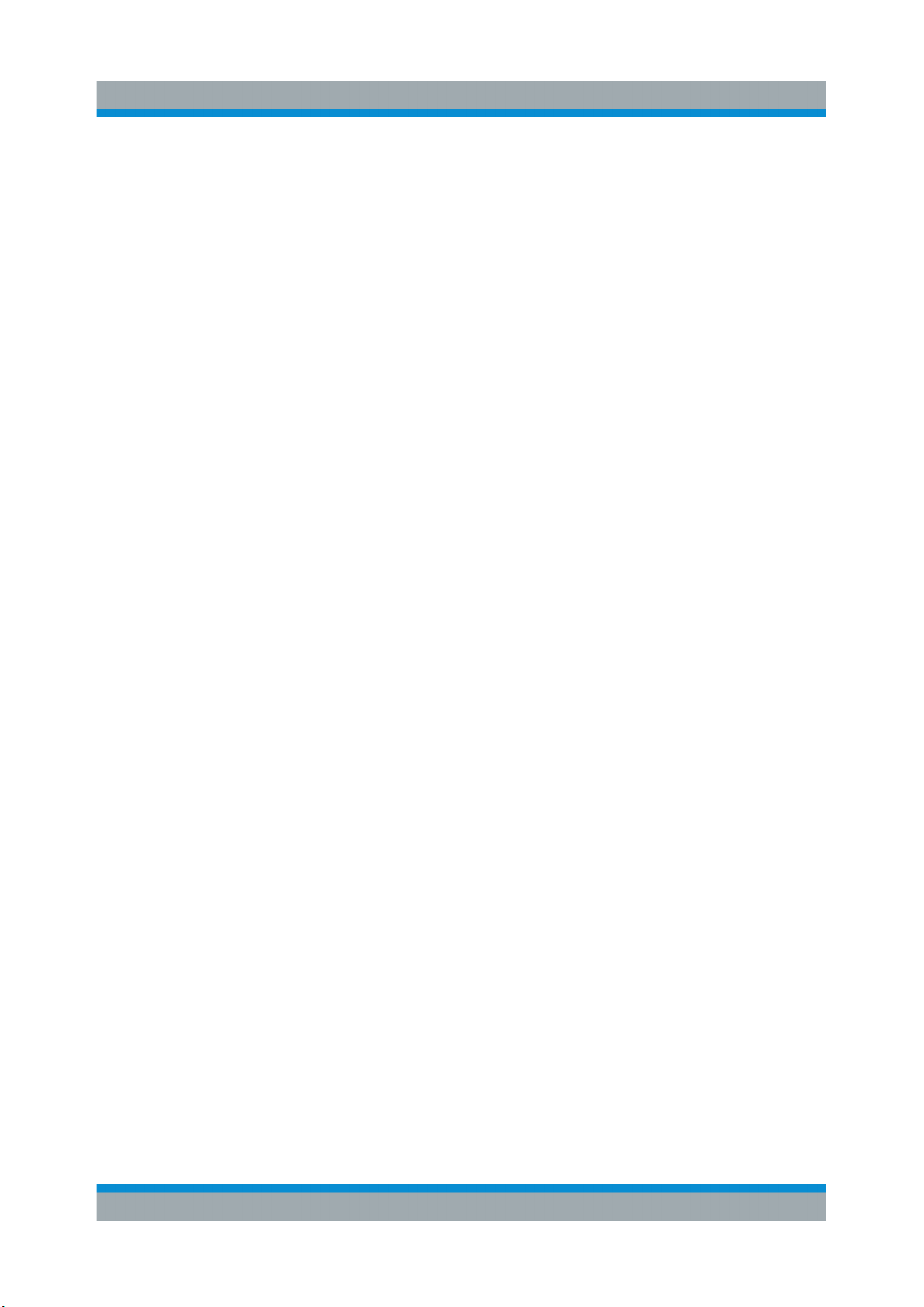
R&S®SMW200A
Applications Examples of the R&S SMW
System Overview
7.2 Applications Examples of the R&S SMW
Due to its modular design, the R&S SMW can be optimally adapted to the
requirements of different applications:
●
Generation of digitally modulated signal
The main field of application of the R&S SMW is the generation of digitally
modulated signals. The R&S SMW generates a digitally modulated signal in
several ways: using the internal baseband generator, using the externally
applied digital baseband signals or in an analog wideband I/Q operation.
●
Generation of test signals for diversity tests and MIMO scenarios
The R&S SMW enables you to generate test signals in versatile MIMO configuration for which several signal generators were previously required.
●
Generation of a wanted signal and an interfering signal for receiver tests
●
Addition of real-time signals of different standards, for example EUTRA/LTE
and 3GPP FDD
●
Generation of signals with up to 2 GHz signal bandwidth, for example for
WLAN IEEE 802.11ad signals
●
Generation of fading scenarios, e.g for test setups involving R&S SMW and
R&S®CMW
A few examples are given in the following.
90Getting Started 1412.9220.02 ─ 21
Page 91
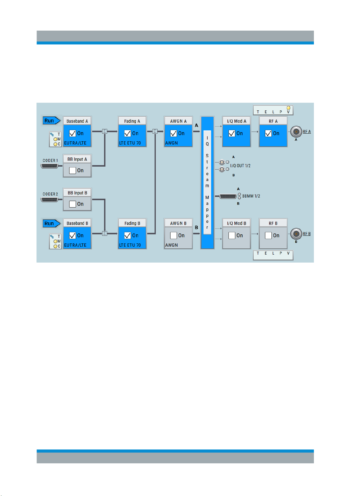
R&S®SMW200A
Applications Examples of the R&S SMW
System Overview
7.2.1 Transmit Diversity Test (MISO Scenario)
The block diagram in this example depicts the generation of a test signal using
both internal baseband generators and 1 RF output (RF A).
91Getting Started 1412.9220.02 ─ 21
Page 92
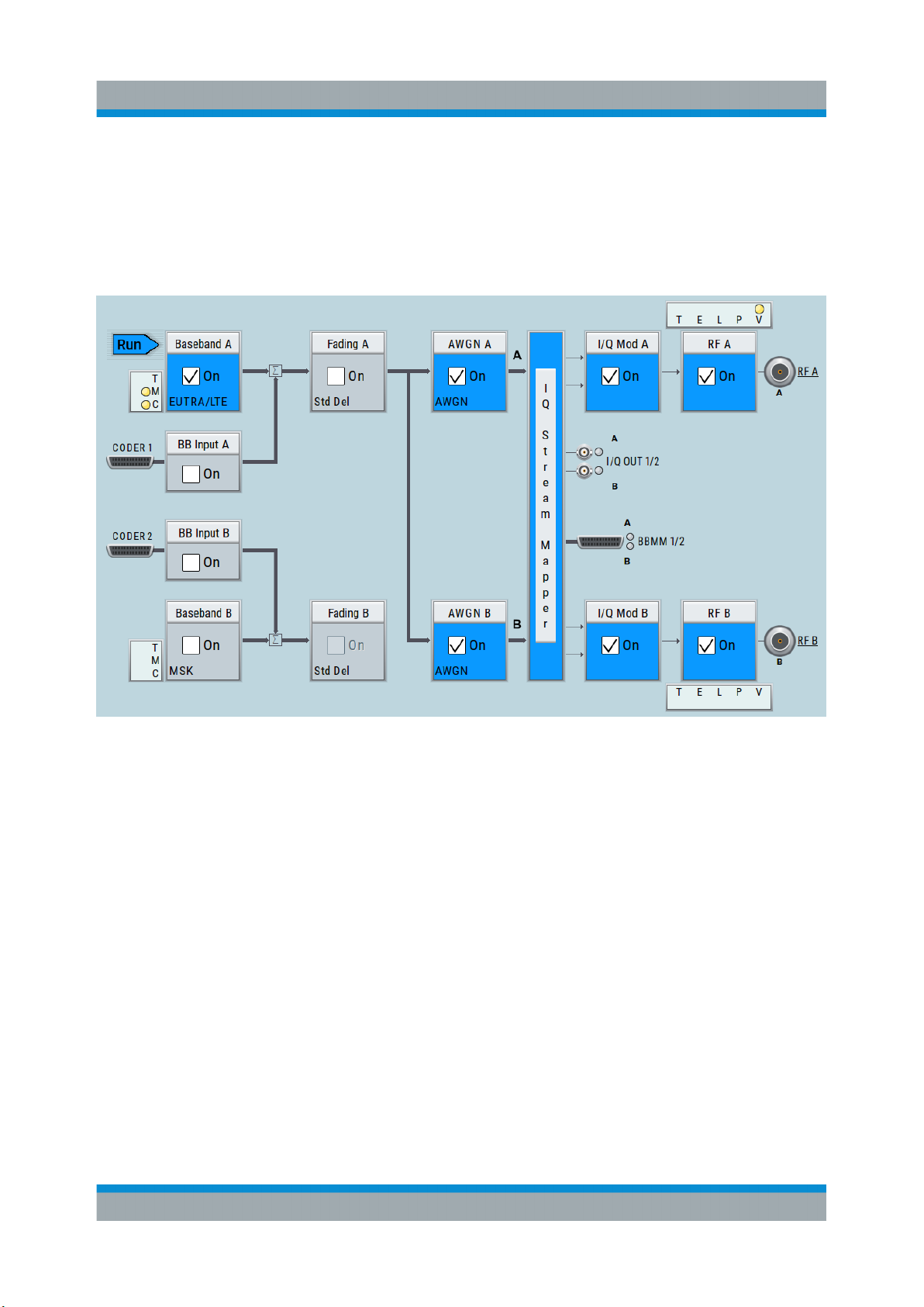
R&S®SMW200A
Applications Examples of the R&S SMW
System Overview
7.2.2 Receive Diversity Test (SIMO Scenario)
The block diagram in this example depicts the generation of a test signal using
one internal baseband generator (Baseband A) and distributing the signal to both
RF outputs.
92Getting Started 1412.9220.02 ─ 21
Page 93
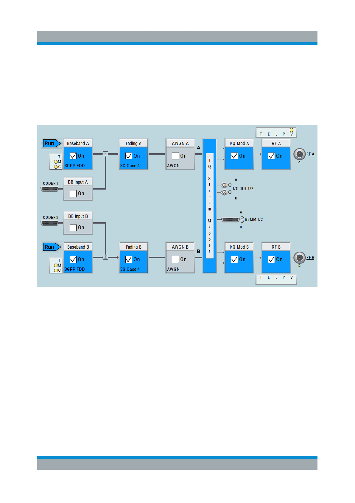
R&S®SMW200A
Applications Examples of the R&S SMW
System Overview
7.2.3 Generation of Signals for Testing of WCDMA Handover
(Two Cells)
The block diagram in this example depicts the generation of a test signal using
both internal baseband generators and both RF outputs, for example for handover tests. The R&S SMW acts as two independent generators in one instrument.
93Getting Started 1412.9220.02 ─ 21
Page 94
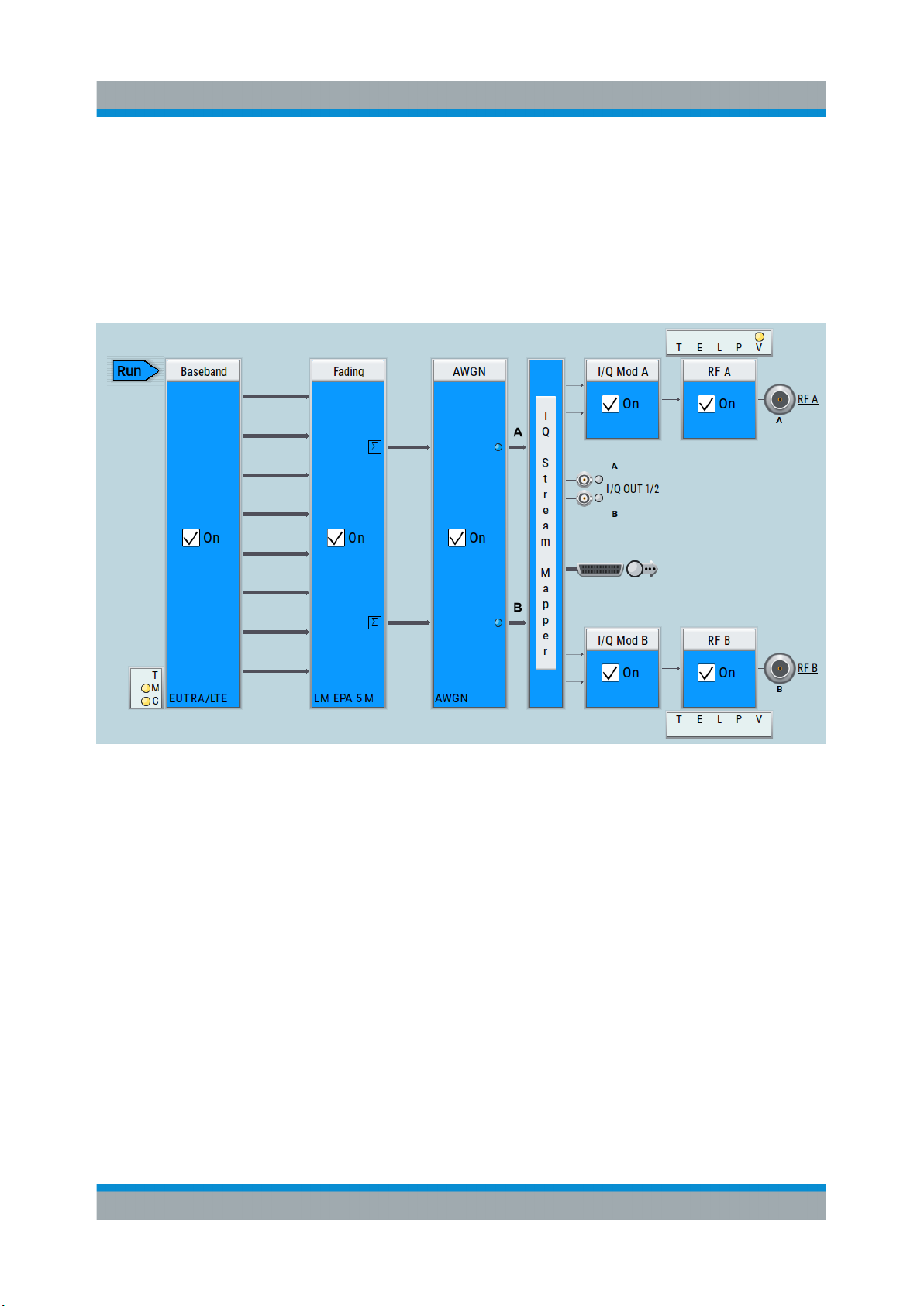
R&S®SMW200A
Applications Examples of the R&S SMW
System Overview
7.2.4 Generation of an EUTRA/LTE 8x2 MIMO Signal for UE
Tests
The block diagram in this example depicts the generation of an EUTRA/LTE test
signal in a 8x2 MIMO scenario, for example for UE tests. The instrument uses a
coupled internal baseband source to generate all required baseband signals.
94Getting Started 1412.9220.02 ─ 21
Page 95
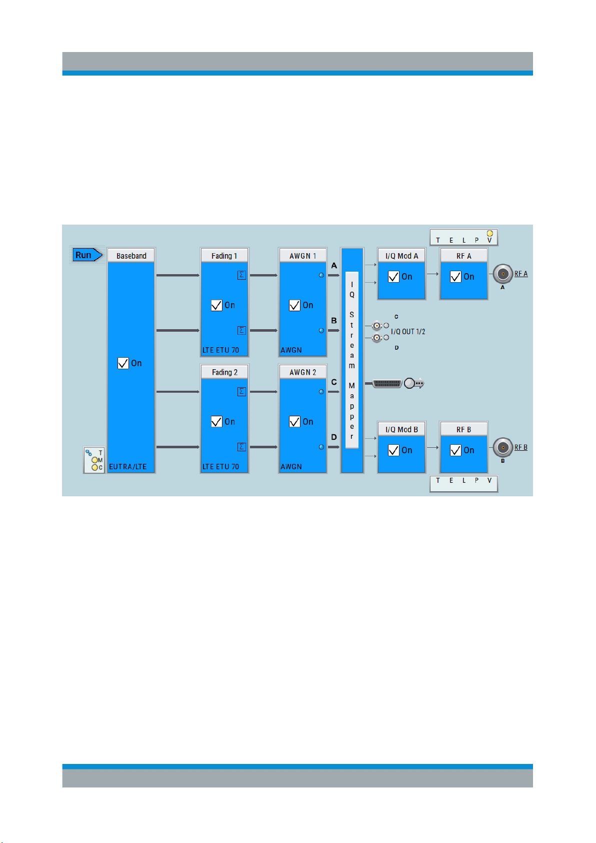
R&S®SMW200A
Applications Examples of the R&S SMW
System Overview
7.2.5 Generation of an LTE Test Signal with Carrier Aggregation
and 2x2 MIMO each Component Carrier
The block diagram in this example depicts the generation of an EUTRA/LTE test
signal with two component carriers (intra-band carrier aggregation) and 2x2
MIMO fading each, for example for UE tests. The instrument uses a coupled
internal baseband source and both RF outputs.
95Getting Started 1412.9220.02 ─ 21
Page 96
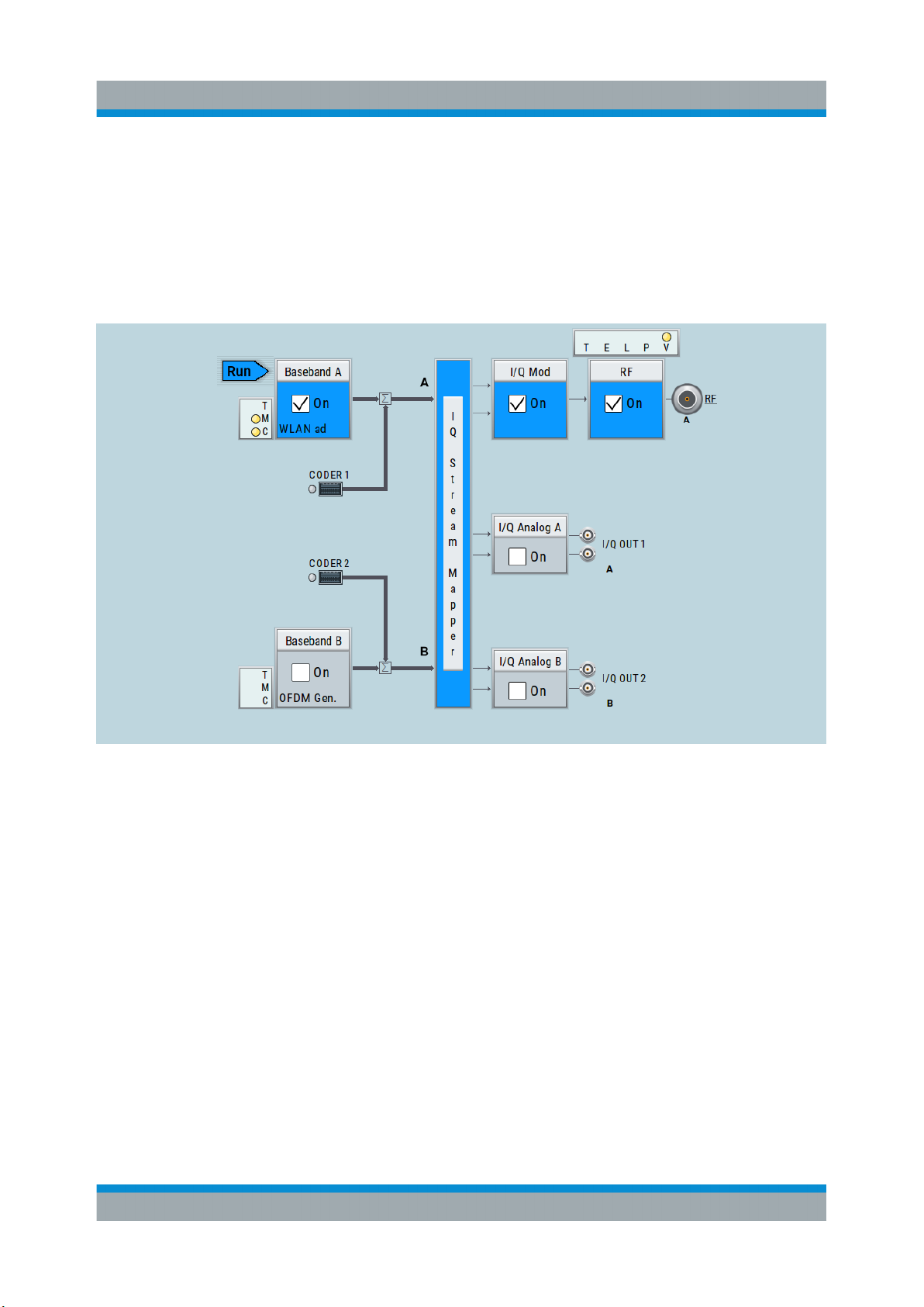
R&S®SMW200A
Applications Examples of the R&S SMW
System Overview
7.2.6 Generation of a WLAN 802.11ad Signal with 1.76 GHz
Bandwidth
The block diagram in this example depicts the generation of a WLAN 802.11ad
test signal with 1.76 GHz bandwidth. The instrument uses one internal wideband
baseband generator with 2 GHz bandwidth and one RF output.
96Getting Started 1412.9220.02 ─ 21
Page 97
R&S®SMW200A
Possible Ways to Operate the Instrument
Instrument Control
8 Instrument Control
This chapter provides an overview on how to work with the R&S SMW.
It covers the following topics:
● Possible Ways to Operate the Instrument.......................................................97
● Means of Manual Interaction...........................................................................98
● Understanding the Display Information........................................................... 99
● Accessing the Functionality...........................................................................105
● Entering Data................................................................................................ 106
● Getting Information and Help........................................................................ 108
● Remote Control............................................................................................. 113
● Remote Operation over VNC.........................................................................114
8.1 Possible Ways to Operate the Instrument
There are three ways to operate the R&S SMW:
●
Manual operation:
Use the touchscreen, hard keys and rotary knob, or an optional mouse and/or
keyboard.
The following description shows how to operate the instrument manually.
●
Remote control:
Create programs to automatize repeating settings, tests and measurements.
The instrument is connected to a computer running the program.
This way of operation is described in the user manual, chapter "Network and
Remote Control Operation".
●
Remote operation from a computer:
Remote monitoring and control of the instrument from a connected computer
is based on the common cross-platform technology VNC (Virtual Network
Computing). On the remote computer, any standard web browser (supporting
Java) or a dedicated VNC client (like Ultr@VNC) can be used. See also Chap-
ter 8.8, "Remote Operation over VNC", on page 114.
97Getting Started 1412.9220.02 ─ 21
Page 98
R&S®SMW200A
Means of Manual Interaction
Instrument Control
8.2 Means of Manual Interaction
For the manual interaction with the R&S SMW, you have several methods that
you can use as an alternative to perform a task:
●
Touchscreen:
Touchscreen operation is the most direct way to interact. Almost all control
elements and actions on the screen are based on the standard operating system concept. You can tap any user interface element to set parameters in dialog boxes, enter data, scroll within a dialog etc., as if you work with a mouse
pointer.
Tapping the screen works like clicking mouse buttons:
– Touch quickly = click: Selects a parameter or provokes an action.
– Touch and hold = right-click: Opens a context-sensitive menu.
– Touch and drag = drag&drop:
Moves a window (dialog or graphic) by dragging it to a new position on the
screen, or
Routes a signal by selecting a block and dragging to the destination block,
or
Resizes a window (dialog or graphic) by dragging an edge or a corner of a
window to the destination size
– Touch and swipe = drag: Scrolls through the contents of a display element
larger than the screen, e.g. a list or a table.
– Spread or pinch two fingers = zoom out, zoom in:
Increases or decreases the size of an area in a graphical display as it
works on your cell phone
●
Function keys and rotary knob:
The front panel provides nearly all functions and controls to operate the instrument in the classic way, without touchscreen.
●
Optional mouse and/or keyboard:
These devices work like known from PCs. The navigation keys on the front
panel correspond to the keys on the keyboard.
This manual describes the manual interaction with the instrument via the touchscreen. It mentions the alternative methods using the keys on the instrument or
the on-screen keypads if it deviates from the standard operating procedures. The
usage of the touchscreen and navigation keys is described in Chapter 8.4,
"Accessing the Functionality", on page 105.
98Getting Started 1412.9220.02 ─ 21
Page 99
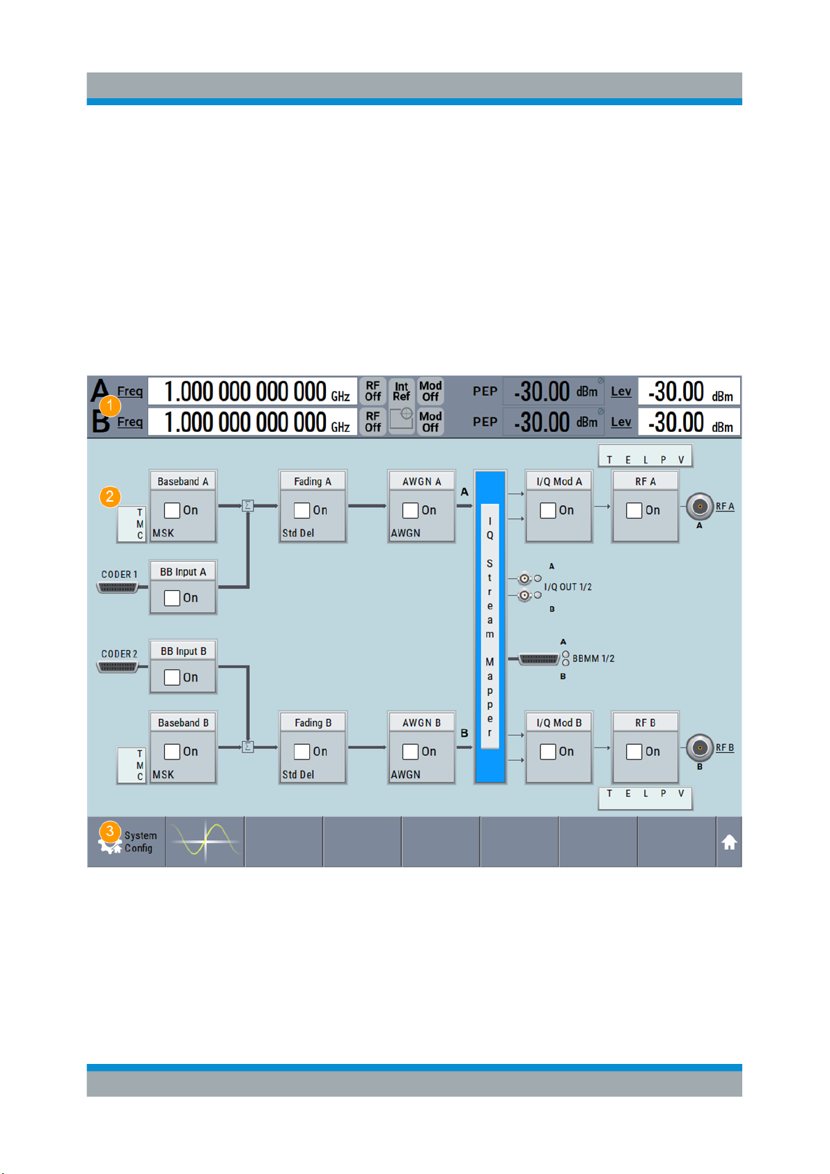
R&S®SMW200A
Instrument Control
Understanding the Display Information
Throughout the manual, the term "select" refers to any of the described methods,
i.e. using a finger on the touchscreen, a mouse pointer in the display, or a key on
the instrument or on a keyboard.
8.3 Understanding the Display Information
The block diagram of the R&S SMW displays all main settings and generator
states, divided into three main operation areas.
Figure 8-1: Block diagram
1 = Status bar
2 = Block diagram
3 = Taskbar/softkey bar
99Getting Started 1412.9220.02 ─ 21
Page 100
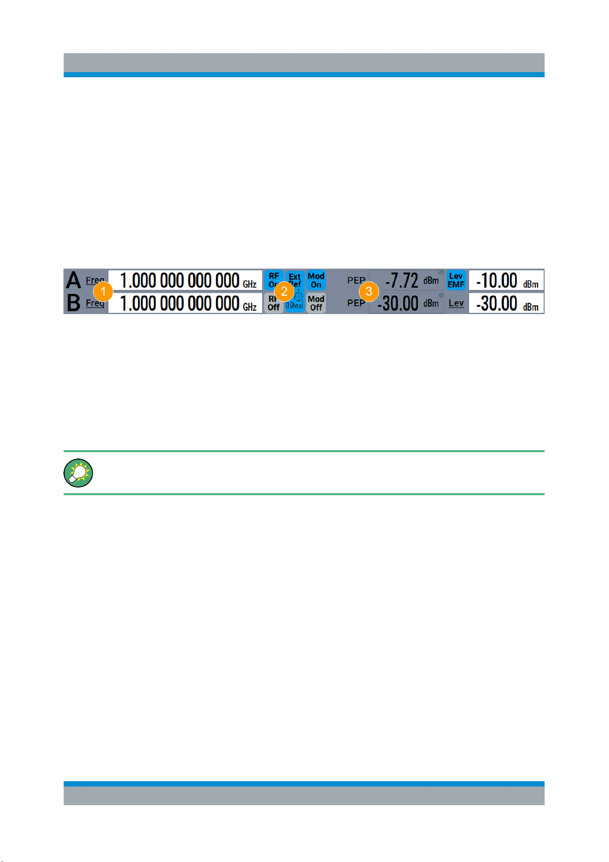
R&S®SMW200A
Instrument Control
Understanding the Display Information
● Status Bar..................................................................................................... 100
● Block Diagram...............................................................................................100
● Taskbar..........................................................................................................102
● Additional Display Characteristics.................................................................103
8.3.1 Status Bar
The status bar at the top of the screen indicates the RF frequency and the level of
the output signal provided to the DUT. You can set both parameters directly here.
1 = Frequency display
2 = Status buttons
3 = Level display
The status buttons indicate key parameters that are set for the output signal. Most
of the status buttons are virtual keys you can use to open a corresponding menu
or dialog.
Underlined names are touch-sensitive. By touching them, you can execute
a setting or access the dialog or menu.
An overview of the status buttons and their functionality is given in the appendix
of the user manual.
8.3.2 Block Diagram
The block diagram shows the current configuration and the signal flow in the generator with the aid of function blocks, connected by signal lines.
The following figure displays almost all the elements that can appear in the block
diagram. However, it does not necessarily represent a useful configuration.
100Getting Started 1412.9220.02 ─ 21
 Loading...