


Bullet 500 Classic
Bullet Classic EFI (C5)
Bullet Electra EFI (E5)
Bullet EFI (G5)

INTRODUCTIONINTRODUCTION
INTRODUCTIONINTRODUCTION
INTRODUCTION
SECTIONSECTION
SECTIONSECTION
SECTION
ONE 01ONE 01
ONE 01ONE 01
ONE 01

01-1
PREFPREF
PREFPREF
PREF
AA
AA
A
CECE
CECE
CE
Part No. 597451 / Qty. 500 / May ‘09
We are pleased to release this workshop manual for the new generation of Royal Enfield
Motorcycles fitted with unit construction engine, electronically controlled “Engine Management
System” and fuel injection technology.
We have endeavoured to make this manual user friendly. However, we welcome your valuable
suggestions for improvements which you may write to us or email us at vvikram@royalenfield.com.
Service Head Quarters,
Royal Enfield
Chennai.
“ © Copyright 2009 EICHER MOTORS LIMITED, UNIT ROYAL ENFIELD.
All Rights Reserved. No part of this Service technical manual shall be copied,
distributed or otherwise dealt, without the express permission in written from Eicher
Motors Limited, Unit Royal Enfield, who remains the sole owner of this manual .”

01-2
FOREWFOREW
FOREWFOREW
FOREW
ORDORD
ORDORD
ORD
PREPARATION FOR SERVICE
Good preparation is very important for carrying out correct service job. The motorcycle should be
cleaned well before starting a repair job. Cleaning will occasionally uncover sources of trouble.
Availability of tools, measuring instruments and parts should be ensured before commensing an
overhaul, since Interruption to locate tools or parts can cause distraction and needless delay. Use of
special tools will ensure a quality service.
USE OF GENUINE SPARE PARTS
Use only genuine Royal Enfield spares whenever replacing parts. Use of non genuine parts can
seriously affect motorcycle performance and may result in costly rework, vehicle down time and
above all customer dissatisfaction.
NOTE :
Proper service and repair is important for the safe and reliable operation of all mechanical products.
The service procedures recommended and detailed in this manual will help to carry out correct repairs.
SAFETY
Every care is taken to ensure that the information given in this manual is correct at the time of going to
print. However, Royal Enfield does not assume responsibility for any damage, loss or injury caused to
the vehicle or to the person carrying out repairs, due to errors or omissions in this manual.
IMPORTANT NOTICE
All images shown are only for reference to explain and may not be exactly the same on the motorcycle.
Technical specifications are subject to change without prior notice.
Because of changes that may occur in the manufacturing process, since this manual was printed, it
is possible some instructions or illustrations found within this manual may differ from those found on
the vehicle. However the technical information found within this manual is correct at the time, when it
was approved for printing.
Future modifications, improvements etc will be communicated to our Authorised Distributors / Importers
as and when changes are done to the motorcycle.

01-3
HOHO
HOHO
HO
W W
W W
W
TT
TT
T
O USE O USE
O USE O USE
O USE
YY
YY
Y
OUROUR
OUROUR
OUR
SERSER
SERSER
SER
VICE MANUVICE MANU
VICE MANUVICE MANU
VICE MANU
ALAL
ALAL
AL
Pictorial presentation of various activities, make
this manual easy to understand and user friendly.
This service manual is divided into 10 Sections
01 to 10. Page numbers for each section starts
with 01. Thus, page 05-10 indicates 10th page
of section 5.
The sections are subdivided into subjects and
presented in the following order.
SECTION ONE O1SECTION ONE O1
SECTION ONE O1SECTION ONE O1
SECTION ONE O1
INTRODUCTIONINTRODUCTION
INTRODUCTIONINTRODUCTION
INTRODUCTION
The manual and its arrangements
SECTION TWO 02SECTION TWO 02
SECTION TWO 02SECTION TWO 02
SECTION TWO 02
GENERALGENERAL
GENERALGENERAL
GENERAL
Salient features of the Unit construction engine
& engine management system
Four stroke cycle operation
Basic terminology of automobiles
Technical specifications
Identification of Chassis No., Engine No.,
List of special tools and its applications
Control cables and wiring harness routing.
SECTION THREE 03SECTION THREE 03
SECTION THREE 03SECTION THREE 03
SECTION THREE 03
SERSER
SERSER
SER
VICE DVICE D
VICE DVICE D
VICE D
AA
AA
A
TT
TT
T
AA
AA
A
Service limits of components
Periodical maintenance chart
SECTION FOUR 04SECTION FOUR 04
SECTION FOUR 04SECTION FOUR 04
SECTION FOUR 04
ENGINEENGINE
ENGINEENGINE
ENGINE
Lubrication system
Roller hydraulic Valve lifter (RHVL)
Auto decompressor
Electric starter system & sprag mechanism
Auto Chain Tensioner Assembly
Engine breather System
Clutch System
Inlet manifold & Throttle body
Blow up Charts.
SECTION FIVE 05SECTION FIVE 05
SECTION FIVE 05SECTION FIVE 05
SECTION FIVE 05
ENGINE DISMANTLINGENGINE DISMANTLING
ENGINE DISMANTLINGENGINE DISMANTLING
ENGINE DISMANTLING
INSPECTION & INSPECTION &
INSPECTION & INSPECTION &
INSPECTION &
ASSEMBLASSEMBL
ASSEMBLASSEMBL
ASSEMBL
YY
YY
Y
Torque Specification - Engine
Engine dismantling procedure
Vital parts - Description
Unidirectional fittings list
Engine assembling procedure
SECTION SIX 06SECTION SIX 06
SECTION SIX 06SECTION SIX 06
SECTION SIX 06
ENGINE MANENGINE MAN
ENGINE MANENGINE MAN
ENGINE MAN
AA
AA
A
GEMENTGEMENT
GEMENTGEMENT
GEMENT
SYSY
SYSY
SY
STEMSTEM
STEMSTEM
STEM
Functional Diagram
Components description
Function of components
Identification of a malfunction in EMS
Do’s & Dont’s
Trouble shooting
SECTION SEVEN 07SECTION SEVEN 07
SECTION SEVEN 07SECTION SEVEN 07
SECTION SEVEN 07
WHEELS & BRAKESWHEELS & BRAKES
WHEELS & BRAKESWHEELS & BRAKES
WHEELS & BRAKES
Torque Specification - Chassis
Front wheel removal & reassembly
Disc brake
- General instruction
- Master Cylinder & Caliper overhauling
- Bleeding procedure
- Disc inspection
Rear wheel removal & reassembly
Rear Brake removal & reassembly

01-4
SECTION EIGHT 08SECTION EIGHT 08
SECTION EIGHT 08SECTION EIGHT 08
SECTION EIGHT 08
SUSPENSION ANDSUSPENSION AND
SUSPENSION ANDSUSPENSION AND
SUSPENSION AND
STEERINGSTEERING
STEERINGSTEERING
STEERING
Front fork working principle
Front fork removal & reassembly
Steering stem removal & reassembly
Gas filled shock absorber
- Working principle
- Removal and assembly
- Adjustment of shock absorber
- Recharging of shock absorber
Swing Arm
- Removal
- Bush lubrication / replacement
- Reassembly
Centre Stand Removal & Reassembly
SECTION NINE 9SECTION NINE 9
SECTION NINE 9SECTION NINE 9
SECTION NINE 9
ELECTRICALSELECTRICALS
ELECTRICALSELECTRICALS
ELECTRICALS
Electrical symbols
Battery
- Precautions
- Charging
- Maintenance
Spark plug maintenance & Inspecton
Checking procedure of electrical
components:
- Starter coil
- Pulsar coil
- Ignition coil
- Suppressor Cap
- Battery
- Horn
- Relay starter
- Starter motor
- IC Flasher
- RR Unit
- TPS Unit
Electrical parts Inspection
- Clutch switch
- Starter switch
- Switch modules LH & RH
Do’s and Dont’s
Wiring Diagrams
- Ignition circuit
- Starter and charging
- Complete Wiring diagram
Trouble shooting
SECTION TEN 10SECTION TEN 10
SECTION TEN 10SECTION TEN 10
SECTION TEN 10
TRTR
TRTR
TR
OUBLE SHOOOUBLE SHOO
OUBLE SHOOOUBLE SHOO
OUBLE SHOO
TINGTING
TINGTING
TING
SAFETY DEFINITIONSSAFETY DEFINITIONS
SAFETY DEFINITIONSSAFETY DEFINITIONS
SAFETY DEFINITIONS
Important aspects to be noted are given as
follows in the manual.
NOTE
Provides important information that will have to
be adhered to while carrying out repairs.
CAUTION
Indicates activities that are important to be
noted. Non-adherance may result in breakage
and or functional failures of the assembly.
SPECIAL TOOLS
Contains details of the special tools and its
usage, These tools have been specially designed
for a specific purpose.

GENERALGENERAL
GENERALGENERAL
GENERAL
SECTIONSECTION
SECTIONSECTION
SECTION
TWO 02TWO 02
TWO 02TWO 02
TWO 02
02-1
SALIENT FEASALIENT FEA
SALIENT FEASALIENT FEA
SALIENT FEA
TURES OF TURES OF
TURES OF TURES OF
TURES OF
THE UNIT CONSTRTHE UNIT CONSTR
THE UNIT CONSTRTHE UNIT CONSTR
THE UNIT CONSTR
UCTIONUCTION
UCTIONUCTION
UCTION
ENGINE & ENGINE MANENGINE & ENGINE MAN
ENGINE & ENGINE MANENGINE & ENGINE MAN
ENGINE & ENGINE MAN
AA
AA
A
GEMENT SYGEMENT SY
GEMENT SYGEMENT SY
GEMENT SY
STEMSTEM
STEMSTEM
STEM
• HIGH TORQUE ENGINE
• ENHANCED POWER DELIVERY
• HYDRAULIC TAPPETS
• AUTO DECOMPRESSOR
• AUTO CHAIN TENSIONER FOR
PRIMARY CHAIN
• HIGH CAPACITY TRACHOIDAL OIL
PUMP FOR BETTER LUBRICATION
• IMPROVED ACCELERATION & HIGH
SPEED CRUISING
• EXCELLENT COLD STARTING
ABILITY
• ACCURATELY CONTROLLED, AIR
FUEL MIXTURE & IGNITION TIMING
BY THE ENGINE CONTROL UNIT
• IMPROVED PERFORMANCE AND
FUEL EFFICIENCY THRO FUEL
INJECTION SYSTEM.
FOUR STRFOUR STR
FOUR STRFOUR STR
FOUR STR
OKE CYOKE CY
OKE CYOKE CY
OKE CY
CLE OPERACLE OPERA
CLE OPERACLE OPERA
CLE OPERA
TIONTION
TIONTION
TION
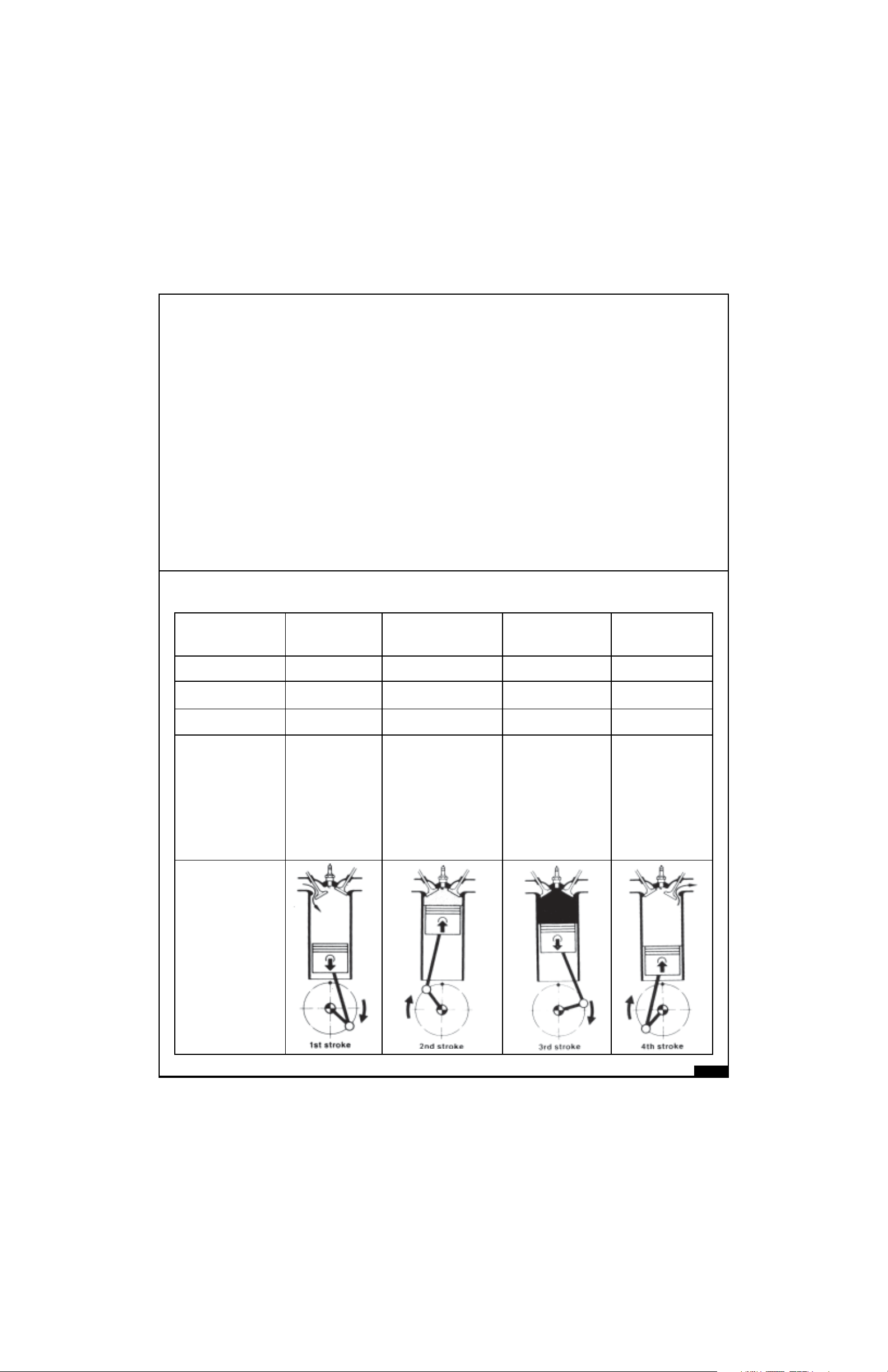
SUCTION COMPRESSION POWER EXHAUST
STROKE
STROKE STROKE STROKE
Inlet Valve Open Closed Closed Closed
Exhaust Valve Closed Closed Closed Open
Piston Movement TDC to BDC BDC to TDC TDC to BDC BDC to TDC
Gas Flow Air Petrol Air Petrol Air petrol mixture Exhaust gas
mixture is mixture gets burns, gas
expands. flows out.
drawn into compressed. Piston is
cylinder Few degrees before pushed down.
BTDC, spark plug
produces spark.
02-2
BASIC BASIC
BASIC BASIC
BASIC
TERMINOLTERMINOL
TERMINOLTERMINOL
TERMINOL
OGY OF OGY OF
OGY OF OGY OF
OGY OF
AUTAUT
AUTAUT
AUT
OMOBILESOMOBILES
OMOBILESOMOBILES
OMOBILES
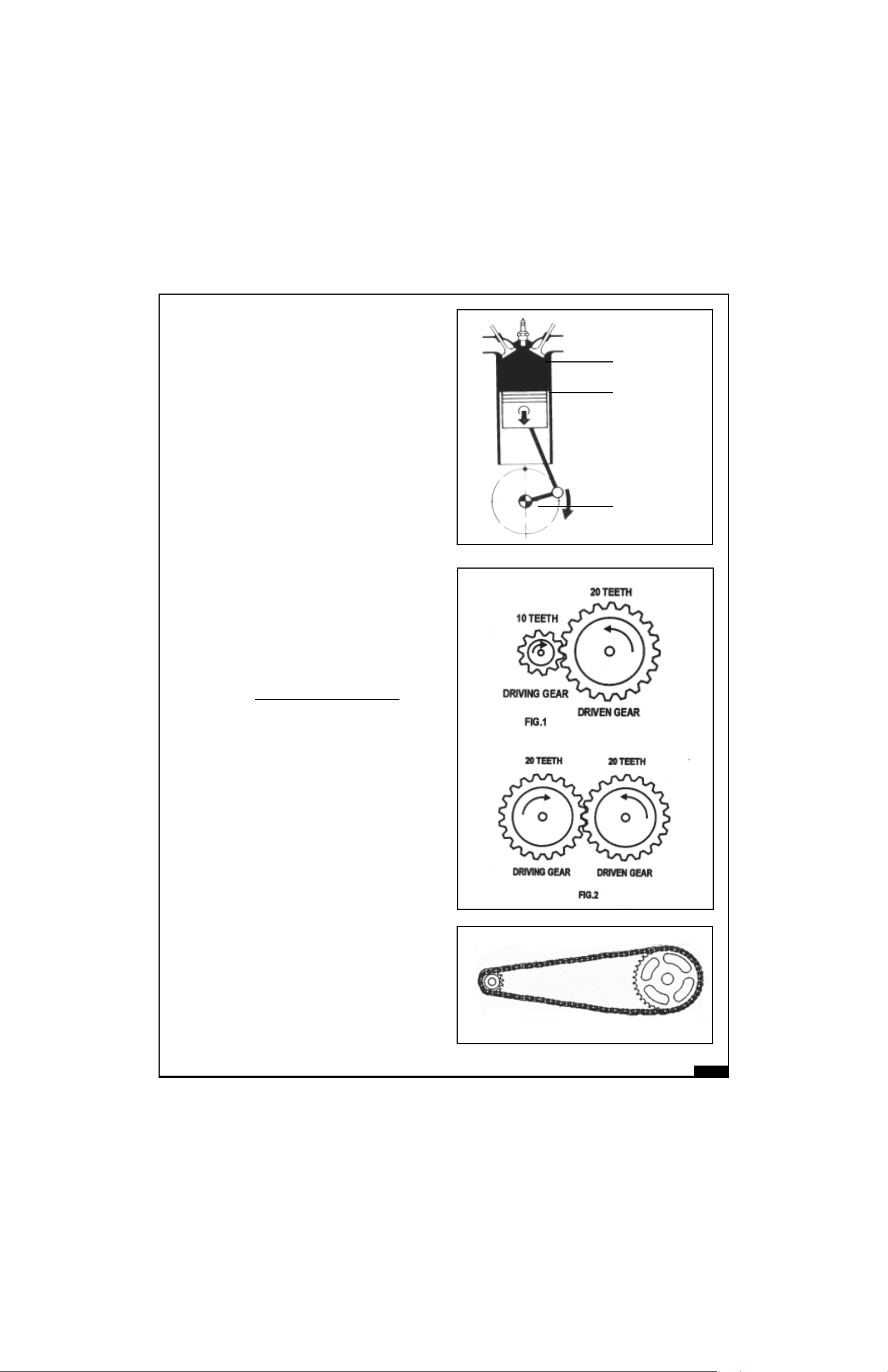
Fuel
Air
Power
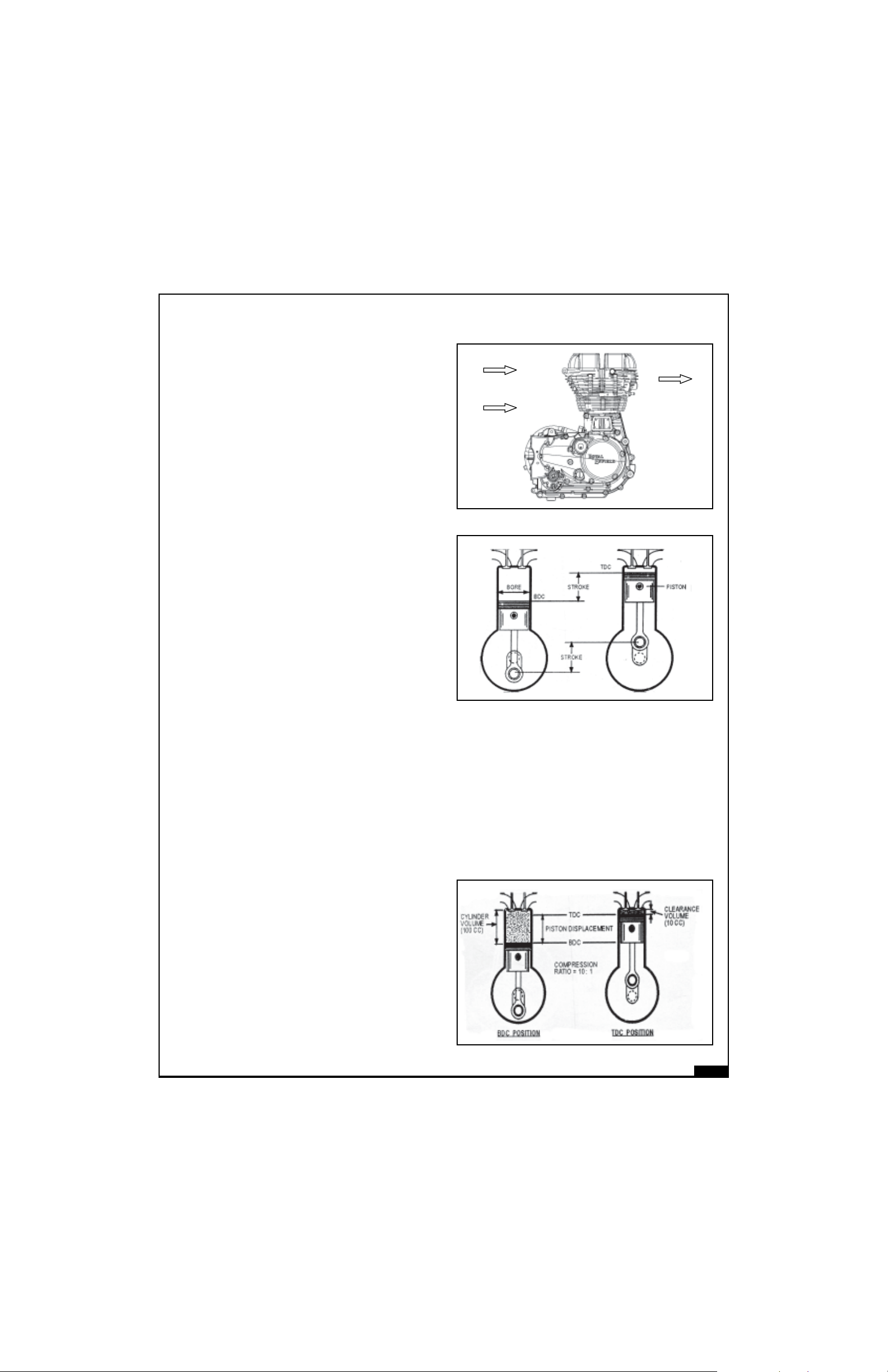
CUBIC CAPACITY / DISPLACEMENT :
It is a volume generated by piston when it travels from TDC to BDC. It is measured as Cubic Centimeter
(CC). It can be mathematically arrived at with the radious of the piston and the stroke of the engine.
(πr²× l, when ‘r’ is the radius of the piston and ‘l’ is the length of the stroke). It is also known as Swept
Volume or Displacement volume.
CLEARANCE VOLUME :
It is the nominal volume of the space above the
piston in the combustion chamber when piston
is at the topmost position (TDC).
ENGINE :
The Engine helps to convert Chemical energy
availbale in petrol into heat energy then to
mechanical energy for motion. It is the heart of
the vehicle in which power is generated for
moving the vehicle.
BORE :
Bore is the inside diameter of the cyclinder block
in which Piston moves up and down.
TDC :
TDC stands for Top Dead Center. It is the top
most position to which the piston can travel in
the cylinder barrel.
BDC :
BDC stands for Bottom Dead Center. It is the
bottom most position to which the piston can
travel in the cylinder barrel.
STROKE :
It is a distance travelled by piston from TDC to
BDC or Vice Versa.

02-3
TOTAL VOLUME :
It is the sum of the swept voume (Displacement volume) and Clearance volume.
Total Volume = Swept volume + Clerance volume.
COMPRESSION RATIO :
It is a ratio between total volume in the engine to the clearance volume available at the end of
compression stroke.
Total volume of air fuel mixture
Clearance volume
VOLUMETRIC EFFICIENCY :
Volumetric efficiency is the ratio between the volume of air fuel mixture that actually enters the cylinder
and Swept volume.
Volumetric Efficiency
= Volume of air fuel mixture inhaled during suction stroke
Swept volume
HORSE POWER (HP OR PS) :
HP : Horse Power
PS : PFERDESTARKE is German unit of power. Horse Power is the ability of the engine to do a
certain amount of work in a given time.
One Horse power is the power required for lifting a weight of 75 Kg. through vertical distance of one
meter in one second.
Conversion :
1PS = 0.986 HP = 0.735 KW
1 HP = 1.014 PS = 0.744 KW
1KW = 1.360 PS = 1.340 HP
Compression ratio =
02-4
IHP :
IHP stands for Indicated Horse Power. Indicated
Horse Power is the power actually developed
inside the engine cylinder by combustion process.
It is utilised to drive the piston.
FHP :
FHP stands for Frictionl Horse Power.
It is the amount of horse power used or lost to
overcome the friction between various engine
components.
BHP :
BHP stands for Brake Horse Power
Brake Horse Power is the amount of Power actually available at the crankshaft or output shaft. It
is calculated by using dynamometer.
BHP = IHP - FHP
MECHANICAL EFFICIENCY :
Mechanical Efficiency is the ratio between Brake horsepower and Indicated horse power.
Brake horsepower = BHP
Indicated Horse power IHP
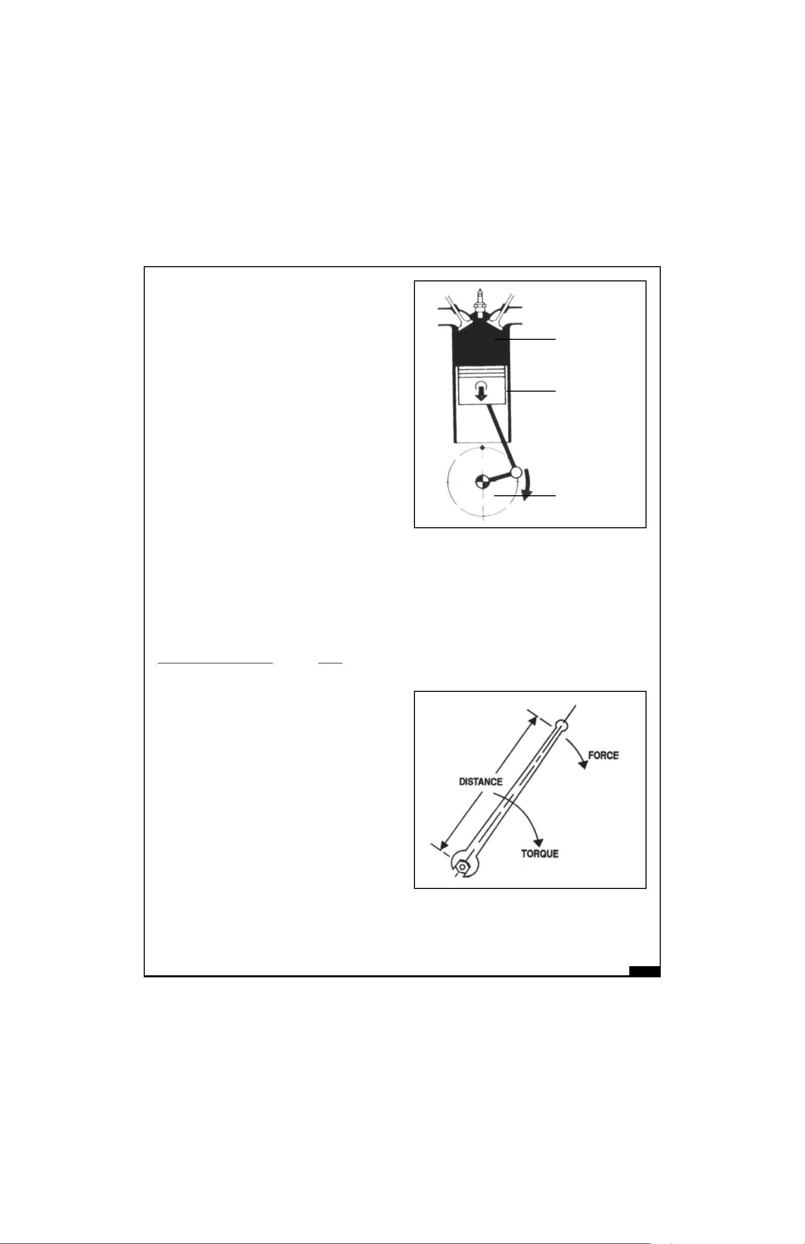
TORQUE :
Torque is a twisting or turning force or effort. It is the
product of a distance and force in circular motion.
In the picture shown the torque-applied is the product
of distance (distance between the center of the bolt
and point where force is acting) and the amount of
force applied.
With the same force, if the distance is increased,
the torque will also increase and if distance is
reduced, torque applied will also be reduced.
CONVERSION :
1kg-m = 7.23 lb.ft = 9.81 N-m.
1lb.ft = 0.138 Kg-m = 1.356 N-m.
1 N-m = 0.102 Kg-m = 0.737 lb.ft
1HP (Horse
Power Available
after explosion)
FHP (Frictional
Losses)
BHP (Horse
Power Avaiable at
Crankshaft)
02-5
IGNITION TIMING :
Ignition timing is the timing at which spark
commences so that the spark from the spark
plug can ignite the mixture in the combusion
chamber at the end of TDC during compression
stroke.
If spark occurs earlier than specified ignition
timing, it is called “Advance” timing.
If spark occurs after the specified ignition timing,
it is called “Retard” timing.
IDLING SPEED :
It is the speed of the crankshaft (i.e. RPM) of the
engine when the throttle is in closed pisition.
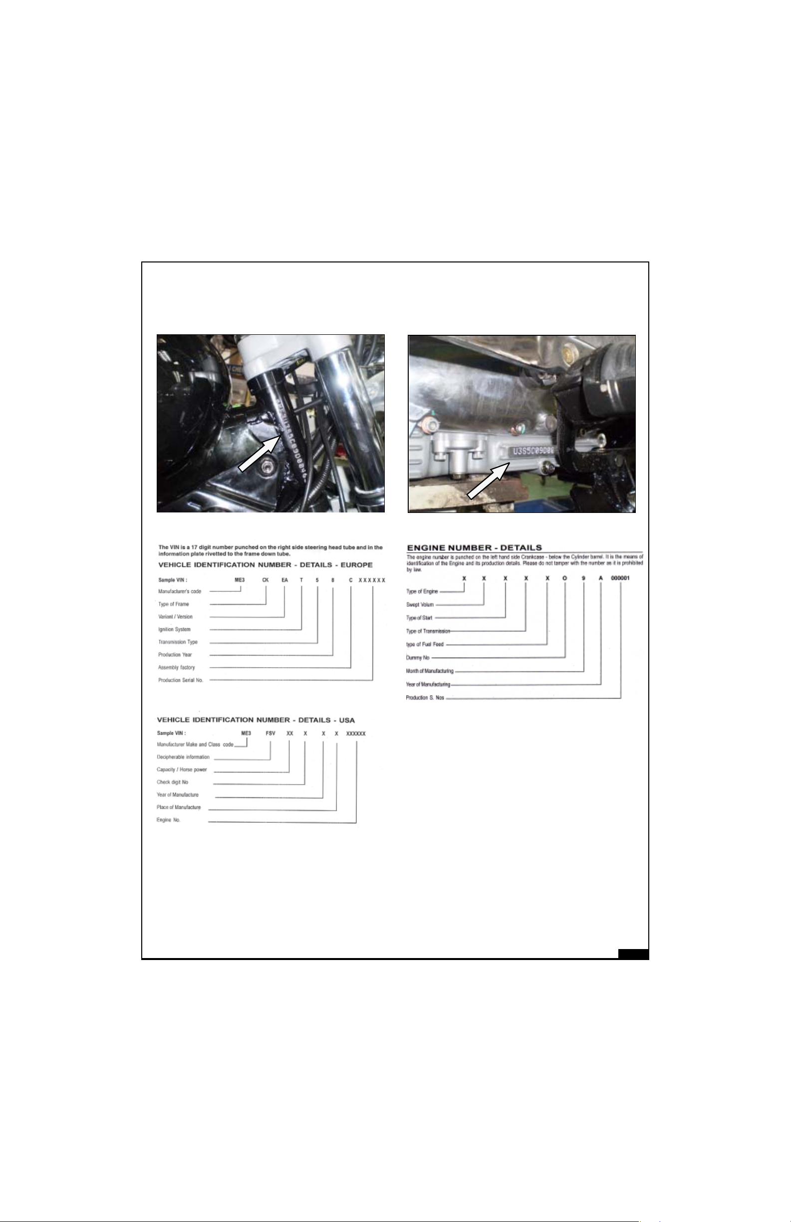
GEAR RATIO :
The relative rotation between “Driven Gear” and
“Driving Gear” is known as the “Gear Ratio”. It is
determined by number of teeth on the respective
gears.
Gear Ratio =
No. of teeth of Driven Gear
No. of teeth of Driving Gear
In Fig. 1, the Gear ratio is 20 ÷ 10 = 2 : 1
In Fig. 2, the Gear ratio is 20 ÷ 20 = 1 : 1
Gear ratios multiply the engine torque to fulfil
various demands for pulling the vehicle like.
- More effort is required during initial
movement of the vehicle.
- More effort is required to climb an elevation.
- More effort is required while driving in
muddy or sandy surfaces.
FINAL DRIVE RATIO :
It is a relative rotation between the engine
sprocket and the sprocket on the rear wheel.
Both the sprockets are connected through drive
chain.
Final drive ratio further multiplies the torque
available at the output shaft.
TDC Position
Ignition Timing
Position
Ignition Timing in
Degrees

02-6
TECHNICAL SPECIFICATECHNICAL SPECIFICA
TECHNICAL SPECIFICATECHNICAL SPECIFICA
TECHNICAL SPECIFICA
TIONSTIONS
TIONSTIONS
TIONS
A. ENGINE AND ENGINE SYSTEMS
BULLET ELECTRA EFI (E5) BULLET CLASSIC EFI
BULLET EFI (G5) (C5)
1. Engine Type 4 Stroke Single Cylinder, Air cooled
2. Bore 84mm
3. Stroke 90mm
4. Displacement 499cc
5. Compression ratio 8.5:1
6. Max Power @ rpm 20.3 Kw @ 5250 rpm
7. Max Torque @ rpm 41.3 Nm @ 4500 rpm
8. Idle rpm 1050 ± 200 rpm
9. Starting Kick & Electric Start Electric Start
10. Air filter element Paper element
11. Lubrication Forced Lubrication, Wet Sump
12. Engine oil tank capacity 2.75 litres
13. Engine oil grade
JASO MA -15W-50, API SL Grade,
ESTER-Semi Synthetic Oil
14. Cooling Natural air flow
B. TRANSMISSION
1. Clutch Wet multiplate
2. Primary drive 3/8” Duplex chain & sprocket
3. Primary ratio 2.15 : 1
4. Gear box 5 Speed Constant Mesh
5. Overall Ratio
1
st
3.063 : 1
2
nd
2.013 : 1
3
rd
1.522 : 1
4
th
1.212 : 1
5
th
1 : 1
6. Secondary drive 5/8” Chain & Sprocket
7. Secondary ratio 2.235 : 1 2.11:1
8. Drive Chain links 101 Pitch 102 Pitch

02-7
C. CHASSIS
BULLET ELECTRA EFI (E5) BULLET CLASSIC EFI
BULLET EFI (G5) (C5)
1. Frame Tubular
2. Front Suspension Telescopic, hydraulic damping, Stroke 130 mm
3. Rear Suspension Swing arm with gas shock absorbers
4. Fr. Fork oil capacity 265 cc + 2.5 cc / each leg
5. Front fork oil SAE 10W -30
6. Front Brake Hydraulic, Hand operated, 280 mm dia ventilated disc
7. Rear Brake Mechanical, Foot operated, 153 mm internal expanding
8. Brake Oil Capacity 60 ml
9. Brake Oil Grade DOT 3 or DOT 4
10. Tyre size : Front 90X90 - 19” - 51V 90X90 - 18” 51V
3.25X19
Rear 100/90 - 19” - 57V 110/80-18” - 58V
3.5X90
D. TYRE PRESSURE
1. Solo : Front 18 PSI
Rear 28 PSI
2. With Pillion : Front 20 PSI
Rear 30 PSI
3. Steering lock In built
4. Fuel tank capacity 14.5 ±1 litres
5. Reserve 2.75 litres
E. ELECTRICALS
1. Generation Alternator
2. System 12V - DC
3. Battery 12V - 14 AH
4. Spark plug Mico - WR7 DDC 4
5. Spark plug gap 0.7 to 0.8 mm
6. Head lamp 12V, 60/55w

02-8
BULLET ELECTRA EFI (E5) BULLET CLASSIC EFI
BULLET EFI (G5) (C5)
7. Tail / Brake Lamp 12V 5 / 21W
8. Speedometer lamp 12V, 3.4W
9. Hi beam indicator 12V, 2W
10. Neutral lamp Tell tale 12V, 2W
11. Turn Signal Tell Tale 12V, 2W
12. Turn signal 12V, 10W
13. Horn 12V DC
F. WEIGHTS
1. Mass of Vehicle in running order 187 Kg.
2. Max pay load 178 Kgs.
3. Max technical permissible mass 365 Kg.
G. DIMENSIONS
1. Length 2200 mm 2160 mm
2. Width 800 mm
3. Height 1100 mm 1050 mm
4. Wheel base 1370 mm
5. Ground clearance 140 mm
6. Saddle height 820 mm 800 mm
H. PERFORMANCE
1. Max. speed 132 Kmph (83 Miles)
NOTE :
1. Values given above are for your guidelines only
2. In view of continuous improvements, specifications are likely to change without
notice
02-9
IDENTIFICAIDENTIFICA
IDENTIFICAIDENTIFICA
IDENTIFICA
TION OF CHASSIS NOTION OF CHASSIS NO
TION OF CHASSIS NOTION OF CHASSIS NO
TION OF CHASSIS NO
.,.,
.,.,
.,
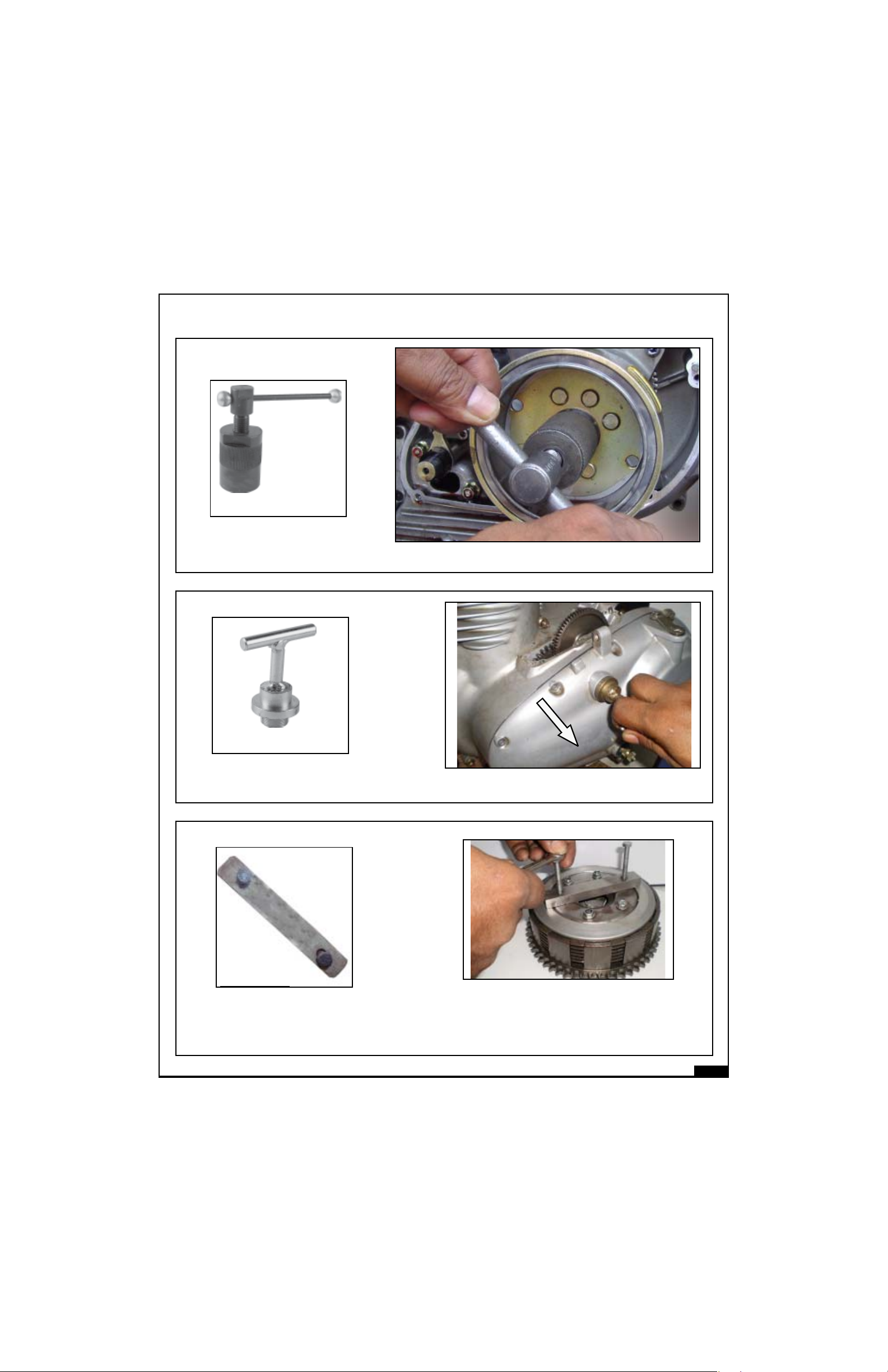
ENGINE NO ENGINE NO
ENGINE NO ENGINE NO
ENGINE NO
,,
,,
,
ENGINENO.
CHASSIS NO.
02-10
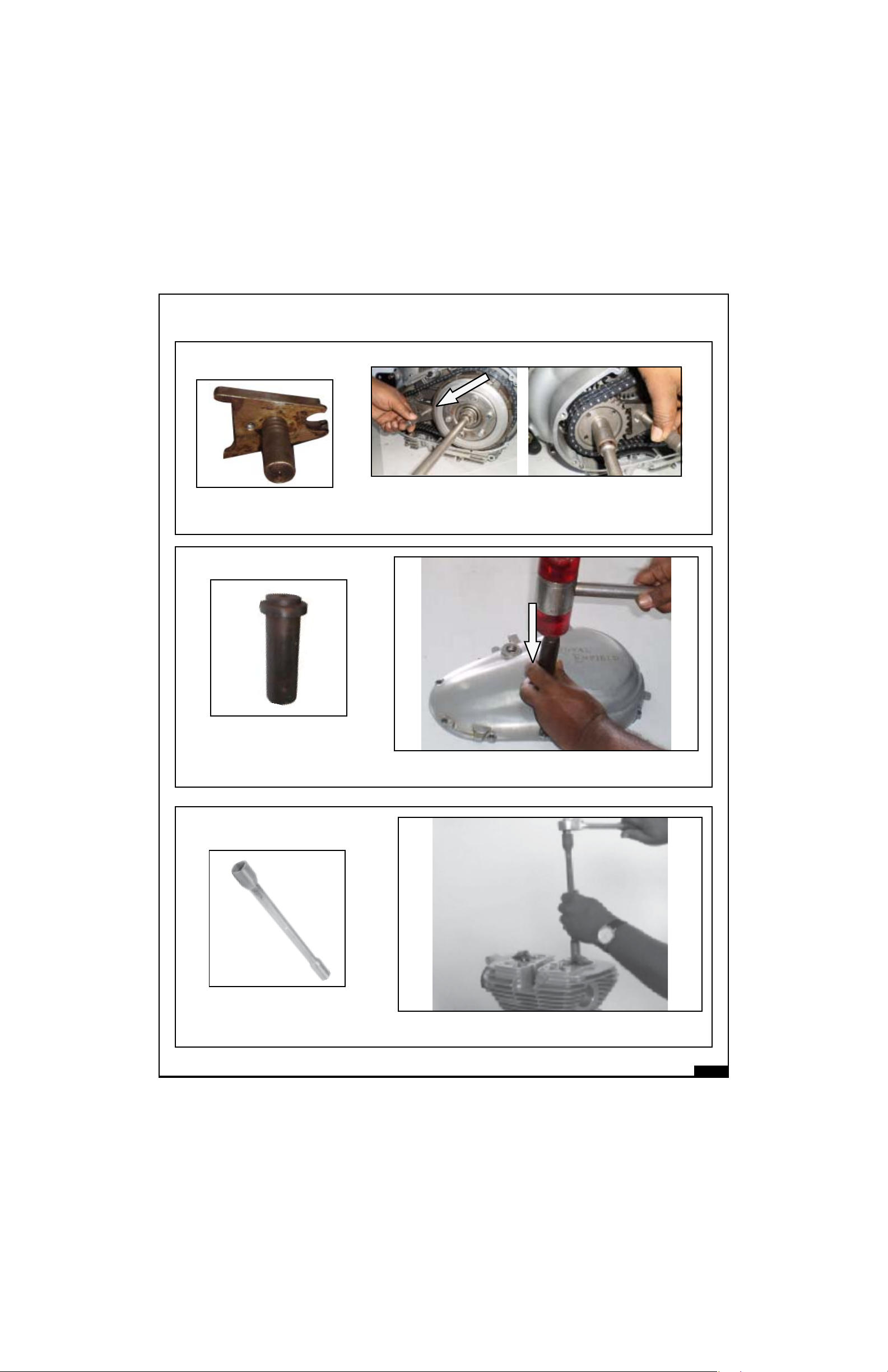
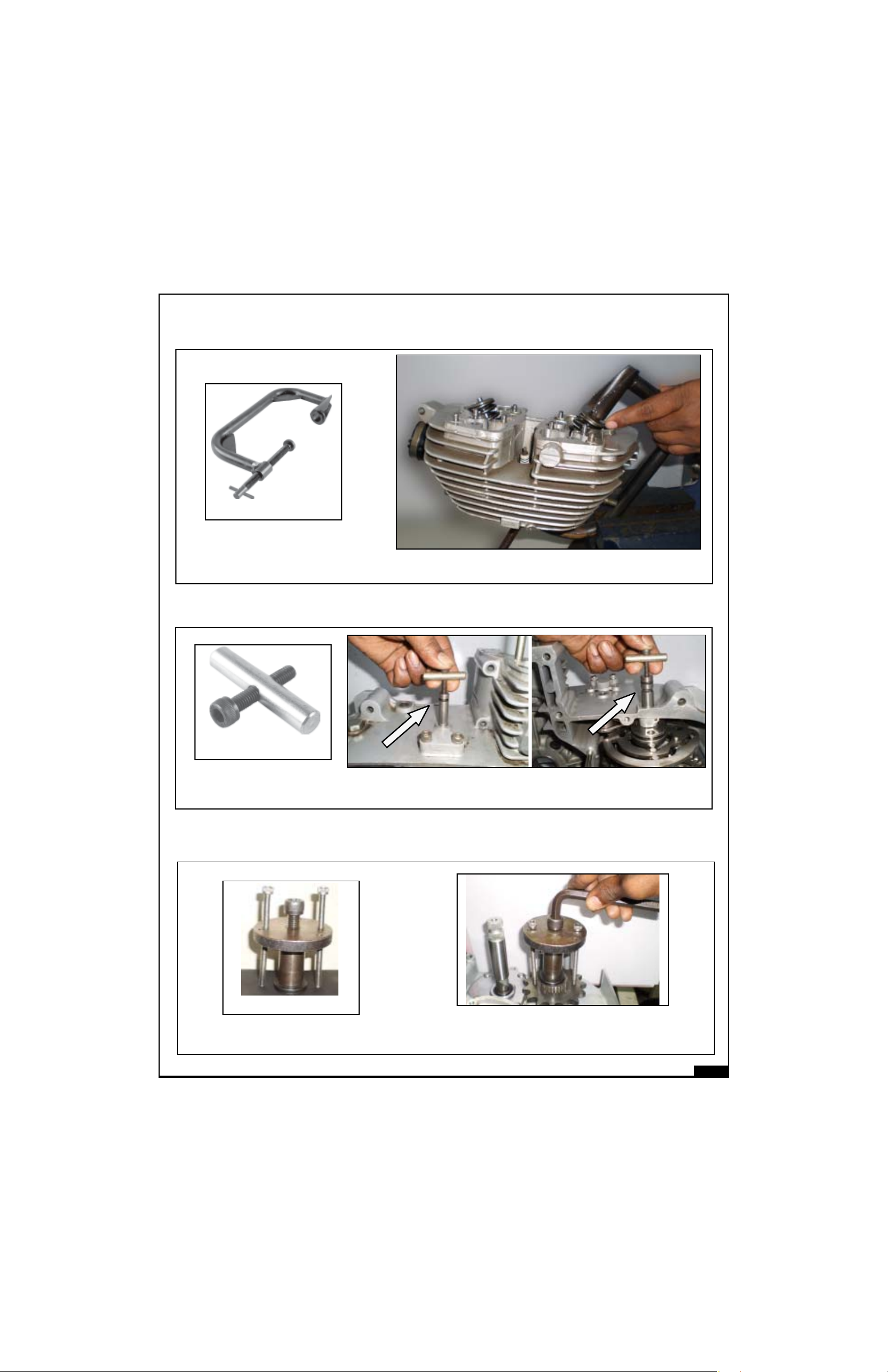
ST 25128-2
Magneto Puller for TCI
Chain case outer puller (TCI)
Application : Removal of magneto assembly
Application : To compress clutch springs while
removing & refitting Clutch plates.
ST-25594-4
Clutch spring assy.
Application :To remove Crank case LH cover
LIST OF SPECIAL LIST OF SPECIAL
LIST OF SPECIAL LIST OF SPECIAL
LIST OF SPECIAL
TT
TT
T
OOLS OOLS
OOLS OOLS
OOLS
AND ITS AND ITS
AND ITS AND ITS
AND ITS
APPLICAAPPLICA
APPLICAAPPLICA
APPLICA
TIONTION
TIONTION
TION
ST 25151-4
02-11
LIST OF SPECIAL LIST OF SPECIAL
LIST OF SPECIAL LIST OF SPECIAL
LIST OF SPECIAL
TT
TT
T
OOLS OOLS
OOLS OOLS
OOLS
AND ITS AND ITS
AND ITS AND ITS
AND ITS
APPLICAAPPLICA
APPLICAAPPLICA
APPLICA
TIONTION
TIONTION
TION
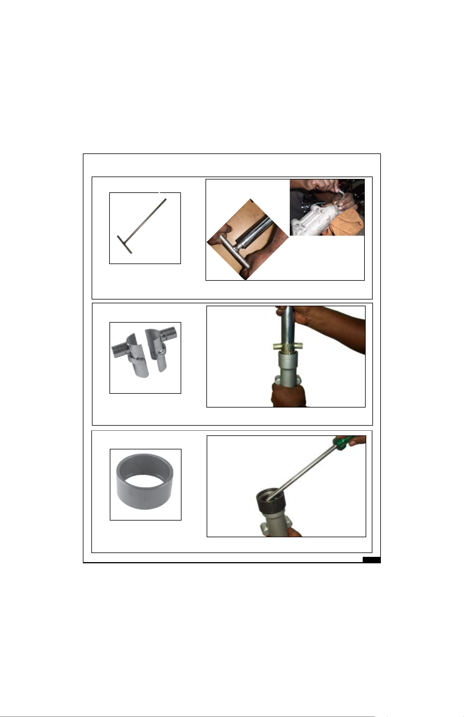
Application : Fitment of gear shaft oil seal on crank case
LH cover.
Application : To remove and tightening of cylinder
head nut.
Oil seal adopter
ST 25118-4
Cylinder head nut tightening tool
Application : To hold Clutch Sprocket while removing / tightening
the Clutch & Sprag Sprocket Nut.
Clutch centre nut
ST-25591-4
02-12
LIST OF SPECIAL LIST OF SPECIAL
LIST OF SPECIAL LIST OF SPECIAL
LIST OF SPECIAL
TT
TT
T
OOLS OOLS
OOLS OOLS
OOLS
AND ITS AND ITS
AND ITS AND ITS
AND ITS
APPLICAAPPLICA
APPLICAAPPLICA
APPLICA
TIONTION
TIONTION
TION
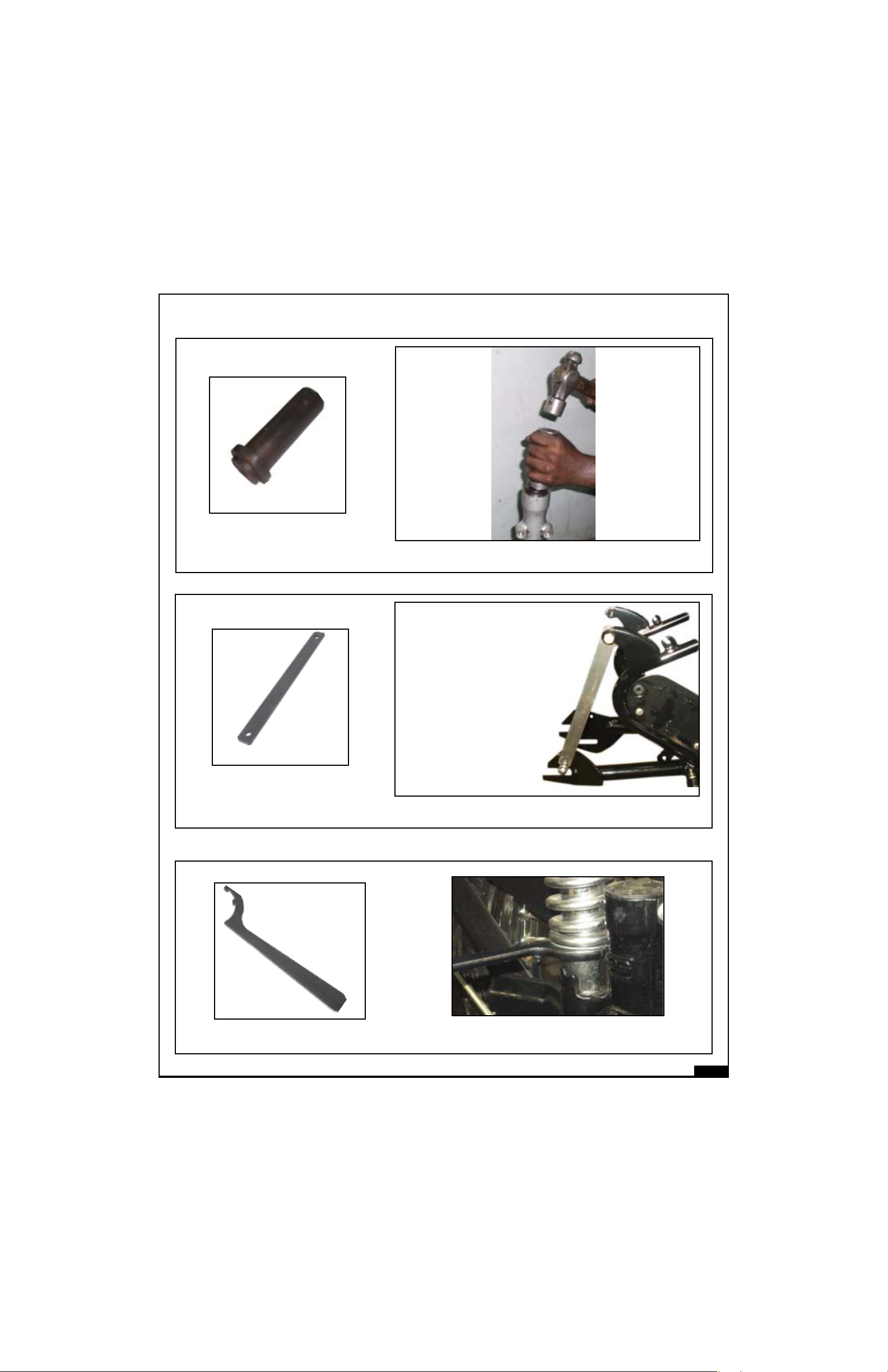
ST 25123-1
Valve Spring compressor
Application : To compress the valve spring for removal
and fitting of valve.
Application : To remove front drive sprocket
from Sleeve Gear.
FD sprocket removal tool
ST 25
ST 25153-4
Extractor for 5 Speed
Gear box Pivot Pin
Application : To remove Gear Rocker Shaft top pivot pin and Gear
Cam Plate pivot pin.
02-13
ST
Front fork main tube spanner
Application : Loosening and tightening of front fork main
tube with fork end
LIST OF SPECIAL LIST OF SPECIAL
LIST OF SPECIAL LIST OF SPECIAL
LIST OF SPECIAL
TT
TT
T
OOLS OOLS
OOLS OOLS
OOLS
AND ITS AND ITS
AND ITS AND ITS
AND ITS
APPLICAAPPLICA
APPLICAAPPLICA
APPLICA
TIONTION
TIONTION
TION
ST 25114-4
Extractor for Fork oil seal
Application : Removal of oil seal in front fork bottom tube
ST 25112-4
Expander for front fork oil seal
Application : Expander for oil seal while inserting main
tube into bottom tube of front fork
02-14
ST 25113-4
Mandrel for oil seal
Application : Fitment of oil seal in front fork bottom tube
LIST OF SPECIAL LIST OF SPECIAL
LIST OF SPECIAL LIST OF SPECIAL
LIST OF SPECIAL
TT
TT
T
OOLS OOLS
OOLS OOLS
OOLS
AND ITS AND ITS
AND ITS AND ITS
AND ITS
APPLICAAPPLICA
APPLICAAPPLICA
APPLICA
TIONTION
TIONTION
TION
ST 25244-4
Application :To adjust gas filled shock absorber
Adjuster Special Spanner
ST 25110-3
Gauge for tightening chain stay
Application : Alignment of Swing Arm while tightening
02-15
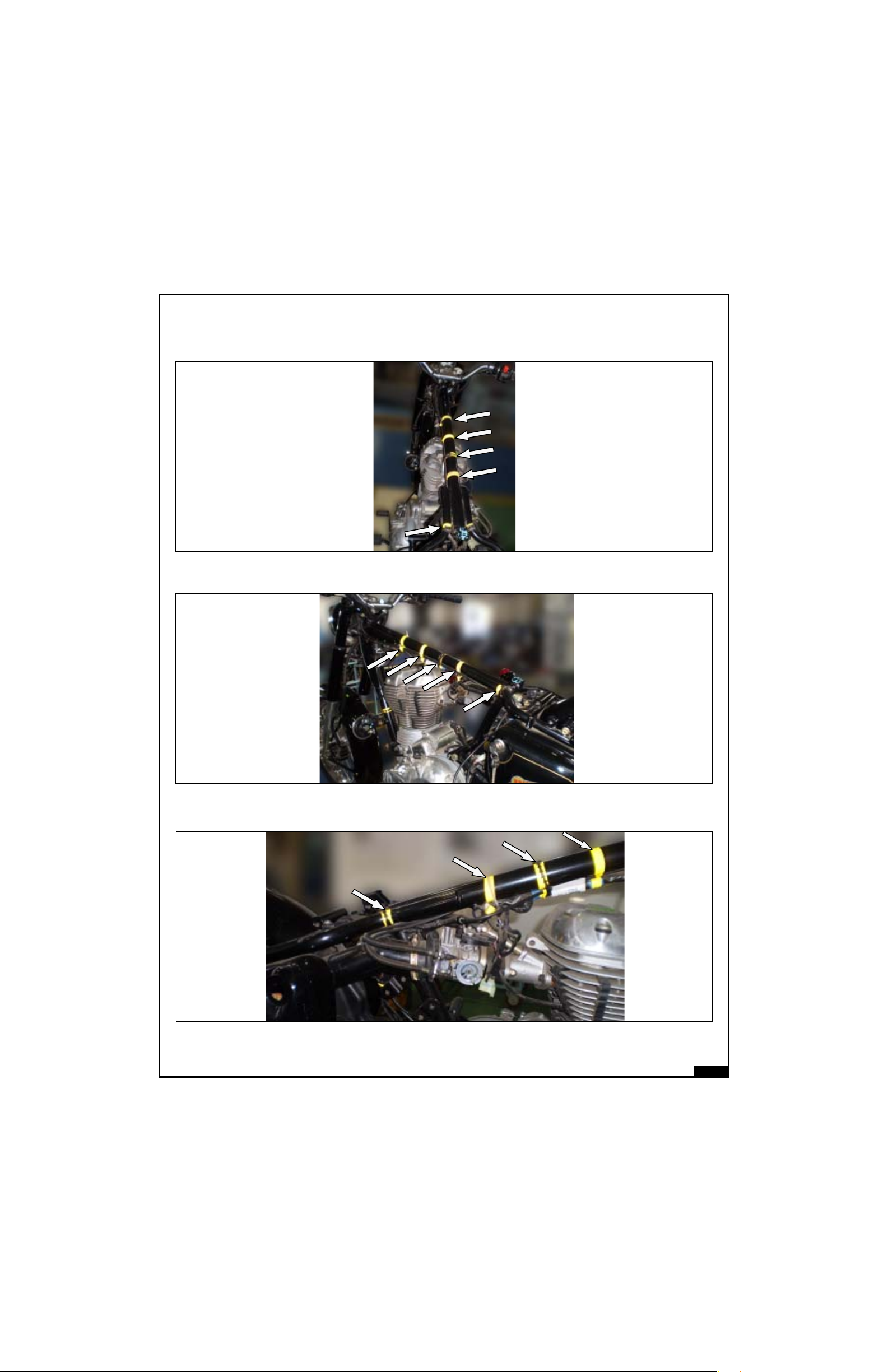
UNDER TANK AND SEAT TOP VIEW
UNDER TANK LH VIEW
UNDER TANK RH VIEW
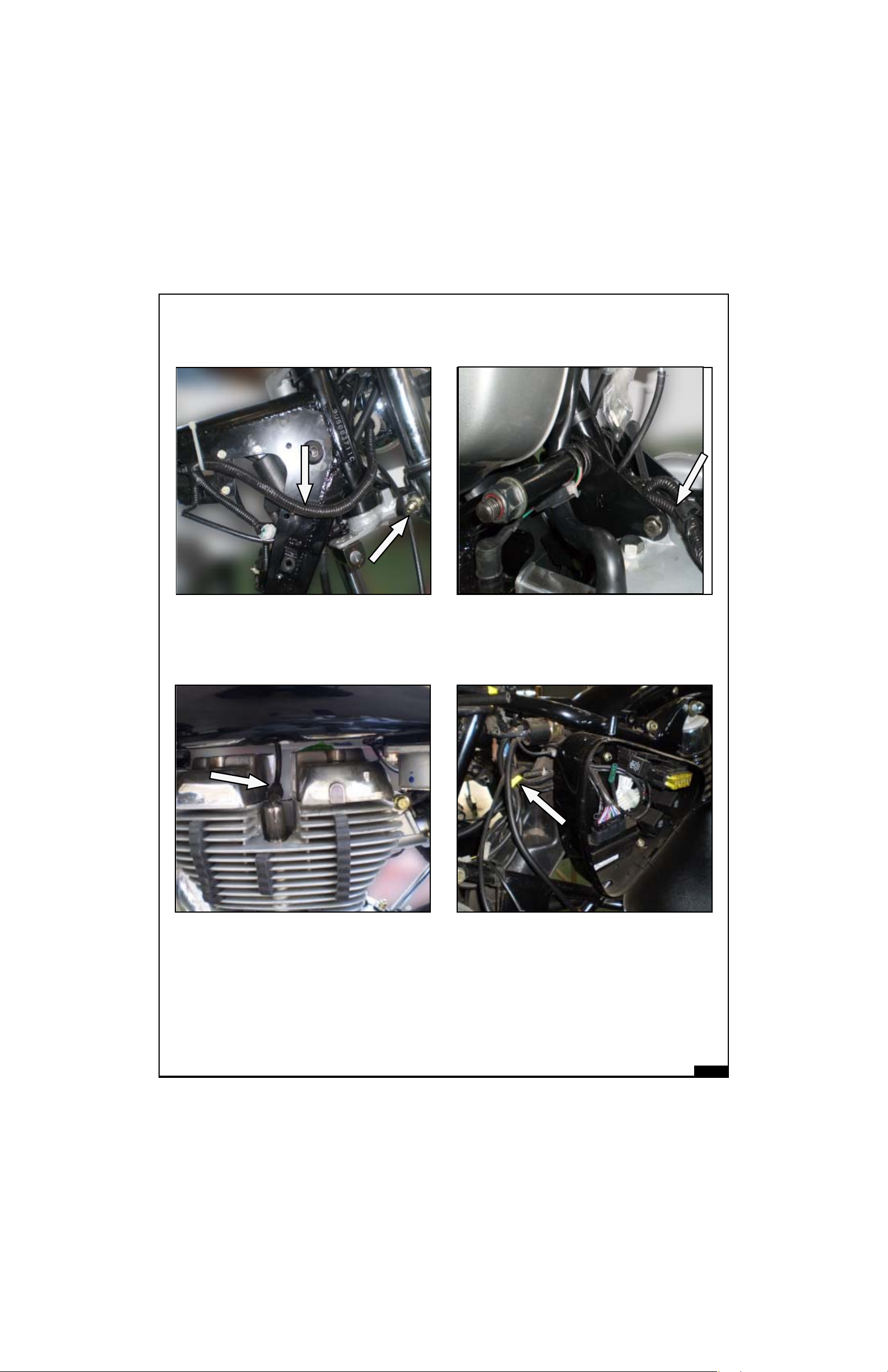
ALL CONTROL CABLES & WIRING HARNESS ROUTING
CONTROL CABLES AND WIRING HARNESS ROUTINGCONTROL CABLES AND WIRING HARNESS ROUTING
CONTROL CABLES AND WIRING HARNESS ROUTINGCONTROL CABLES AND WIRING HARNESS ROUTING
CONTROL CABLES AND WIRING HARNESS ROUTING
02-16
GENERAL GENERAL
GENERAL GENERAL
GENERAL
VEHICLE INFORMAVEHICLE INFORMA
VEHICLE INFORMAVEHICLE INFORMA
VEHICLE INFORMA
TIONTION
TIONTION
TION
HARNESS ROUTING STEERING RH
MAGNETO WIRES ROUTING
PLUG WIRE ROUTING
STARTER RELAY CABLE
ROUTING
02-17
GENERAL GENERAL
GENERAL GENERAL
GENERAL
VEHICLE INFORMAVEHICLE INFORMA
VEHICLE INFORMAVEHICLE INFORMA
VEHICLE INFORMA
TIONTION
TIONTION
TION
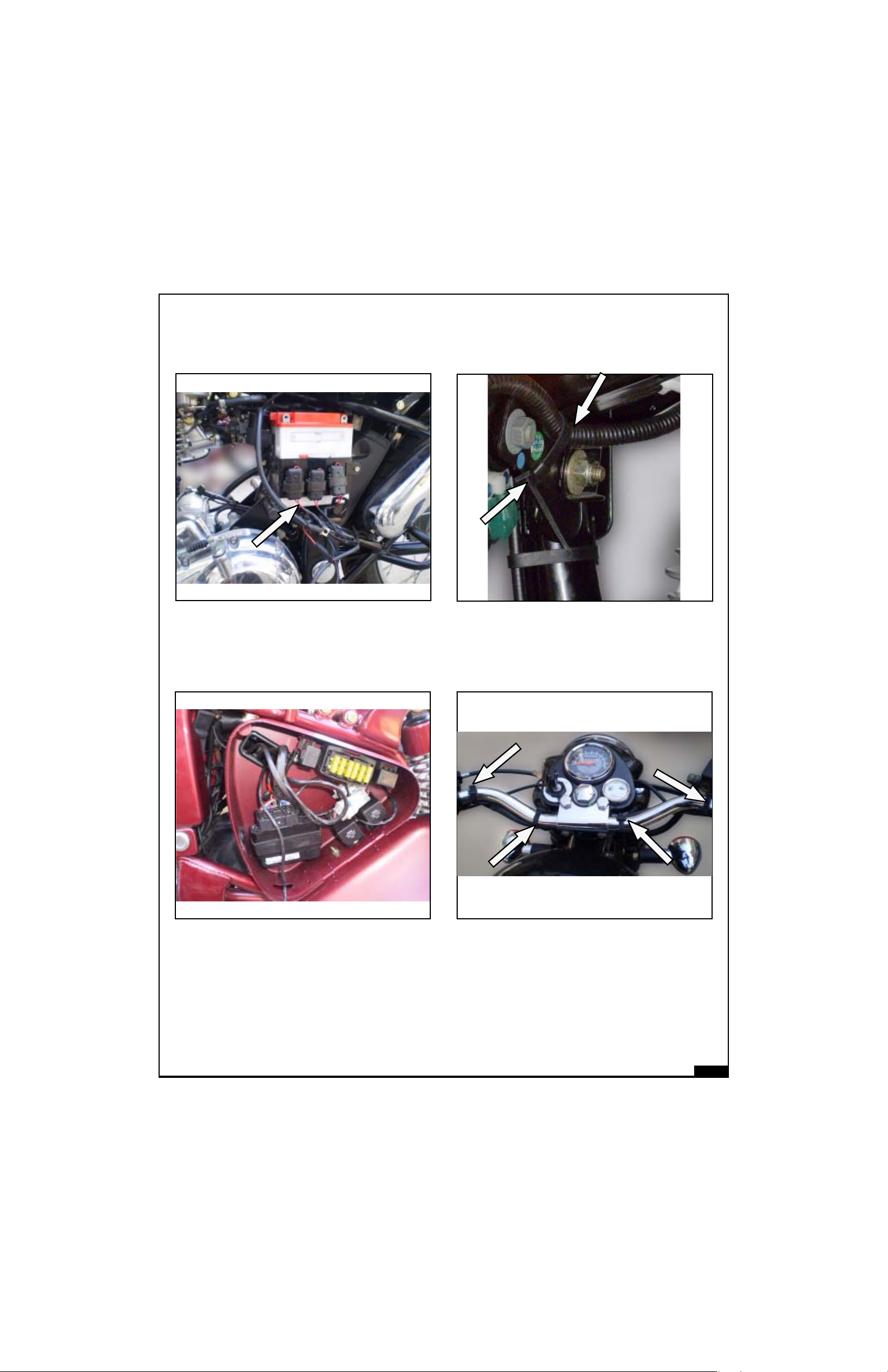
FUSE CARRIERS
ARRANGEMENT (E5 & G5)
HORN WIRE ROUTING
HANDLE BAR WIRES ROUTING
FUSE CARRIERS
ARRANGEMENT (C5)
02-18
GENERAL GENERAL
GENERAL GENERAL
GENERAL
VEHICLE INFORMAVEHICLE INFORMA
VEHICLE INFORMAVEHICLE INFORMA
VEHICLE INFORMA
TIONTION
TIONTION
TION
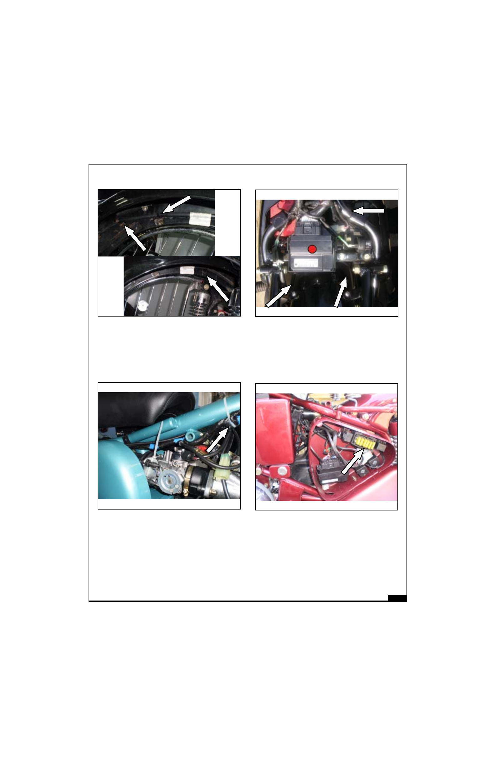
TAIL LAMP & TRAFFICATOR
WIRES ROUTING
ECU MOUNTING BULLET
ELECTRA EFI (E5 & G5)
THROTTLE BODY MOUNTING
WITH CABLES
ECU MOUNTING BULLET
CLASSIC EFI (C5)

SERVICE DSERVICE D
SERVICE DSERVICE D
SERVICE D
AA
AA
A
TT
TT
T
AA
AA
A
SECTIONSECTION
SECTIONSECTION
SECTION
THREE 03THREE 03
THREE 03THREE 03
THREE 03
03-1
SERSER
SERSER
SER
VICE LIMITS OF COMPONENTS VICE LIMITS OF COMPONENTS
VICE LIMITS OF COMPONENTS VICE LIMITS OF COMPONENTS
VICE LIMITS OF COMPONENTS (All units in mm unless specified)
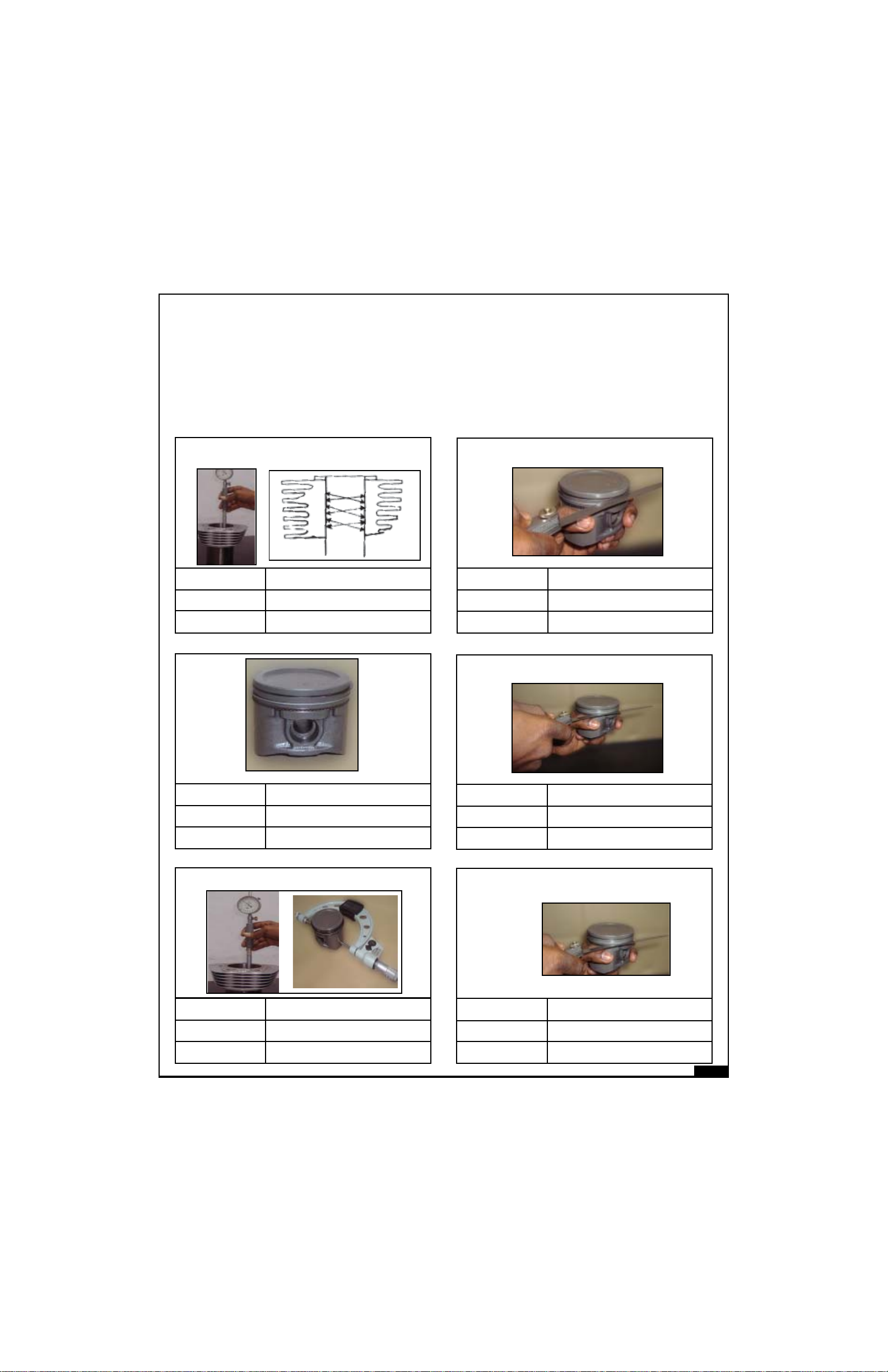
WEAR LIMITS
Wear limits are given as new min, new max and service limits.
New components must be within the limits specified. Components within service limits may be reused
after careful inspection. Use of parts beyond service limit can reduce the operating life of the component
and may affect the motorcycle performance seriously.
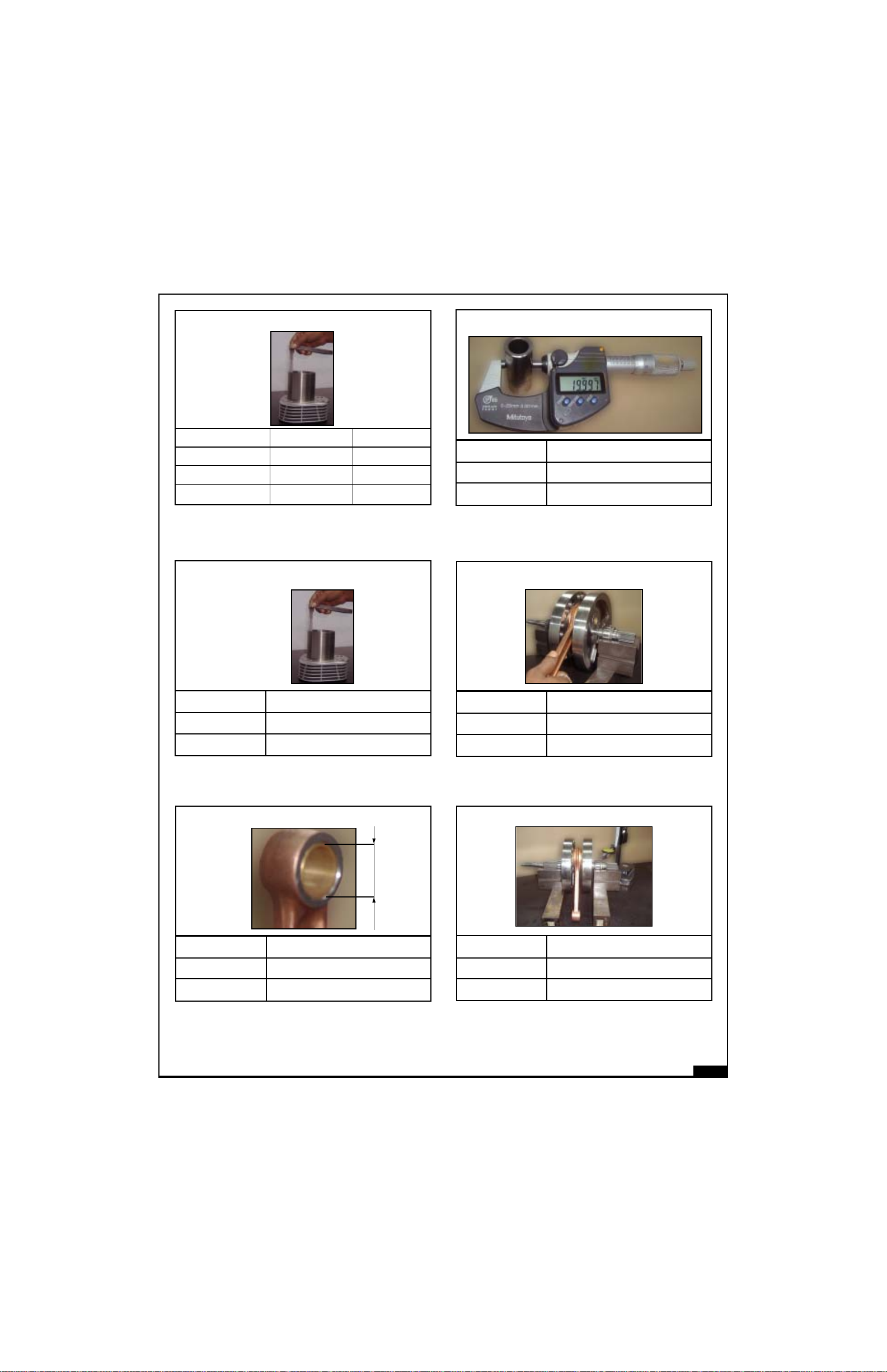
New Min.
New Max.
Service Limit
Ring to groove clearance : oil ring
0.06
0.15
0.21
New Min.
New Max.
Service Limit
0.095
0.115
0.30
Piston to bore clearance
New Min.
New Max.
Service Limit
Ring to groove clearance comp rings - Middle
0.03
0.07
0.15
New Min.
New Max.
Service Limit
Piston
83.940
83.970
83.890
New Min.
New Max.
Service Limit
0.03
0.07
0.11
New Min.
New Max.
Service Limit
84.045
84.075
84.190
Cylinder bore
Cylinder bore :
Point of measurement
Ring to groove clearance : Comp. Top rings
A
B
C
03-2
New Min.
New Max.
Service Limit
Piston ring end gap : compression
Piston Pin diameter
19.992
19.997
19.982
From top 1st 2nd
New Min. 0.20 0.35
New Max. 0.35 0.50
Service Limit 0.70 0.85
New Min.
New Max.
Service Limit
New Min.
New Max.
Service Limit
Piston ring end gap - Oil Ring
Big end axial play
0.20
0.55
0.65
0.20
0.70
0.90
New Min.
New Max.
Service Limit
Crank shaft : Run out
0.00
0.04
0.08
New Min.
New Max.
Service Limit
Small end bore inner diameter
20.007
20.016
20.046
03-3
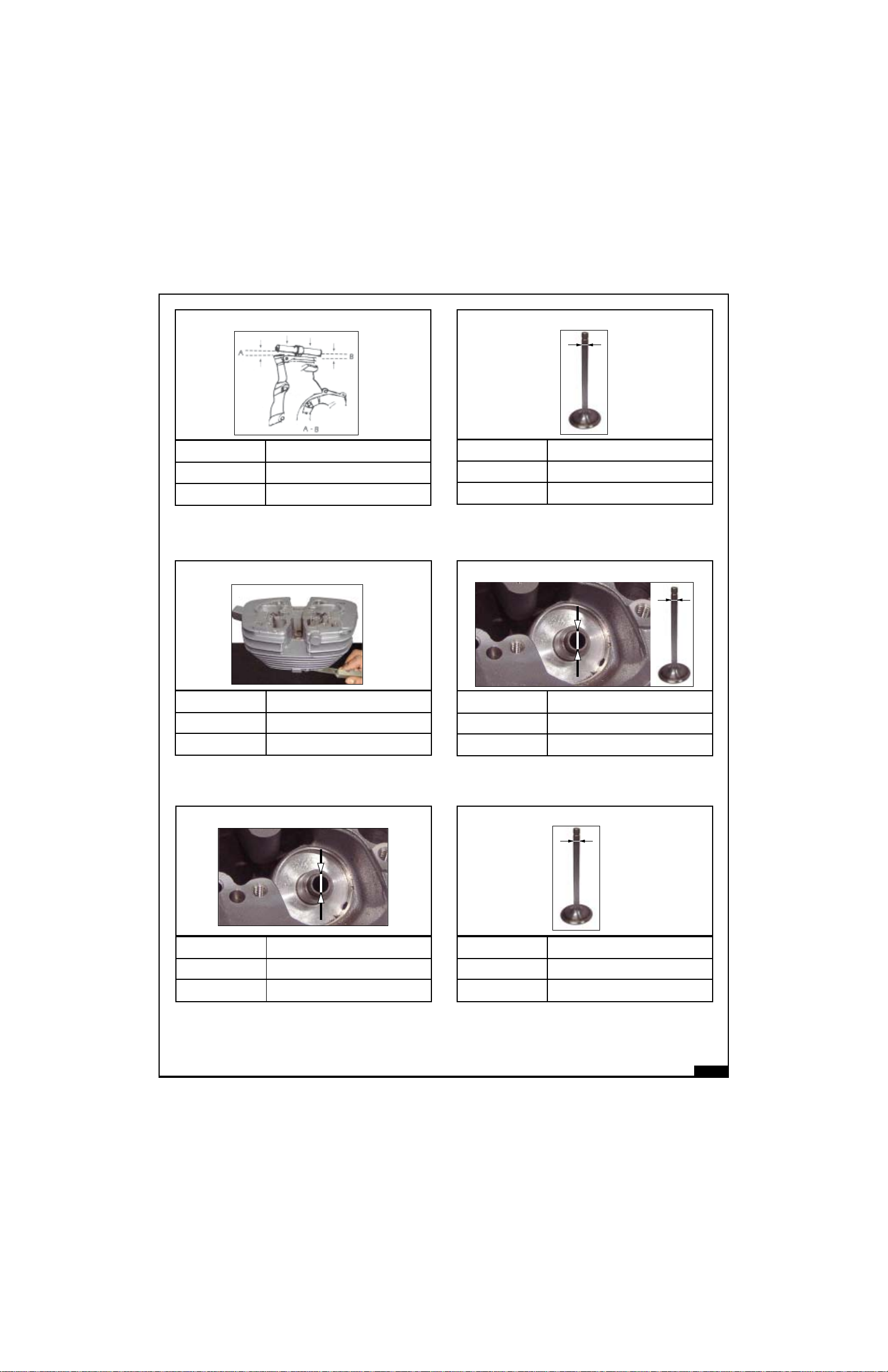
New Min.
New Max.
Service Limit
Connecting rod bend
0.00
0.05
0.08
New Min.
New Max.
Service Limit
Valve stem OD (Inlet)
6.965
6.980
6.955
New Min.
New Max.
Service Limit
Valve to guide (inlet) clearance
0.02
0.05
0.08
New Min.
New Max.
Service Limit
Cylinder Head warpage
0.00
0.05
0.07
New Min.
New Max.
Service Limit
Valve stem OD (Exhaust)
6.945
6.960
6.935
New Min.
New Max.
Service Limit
Valve guide bore
7.00
7.015
7.25
03-4
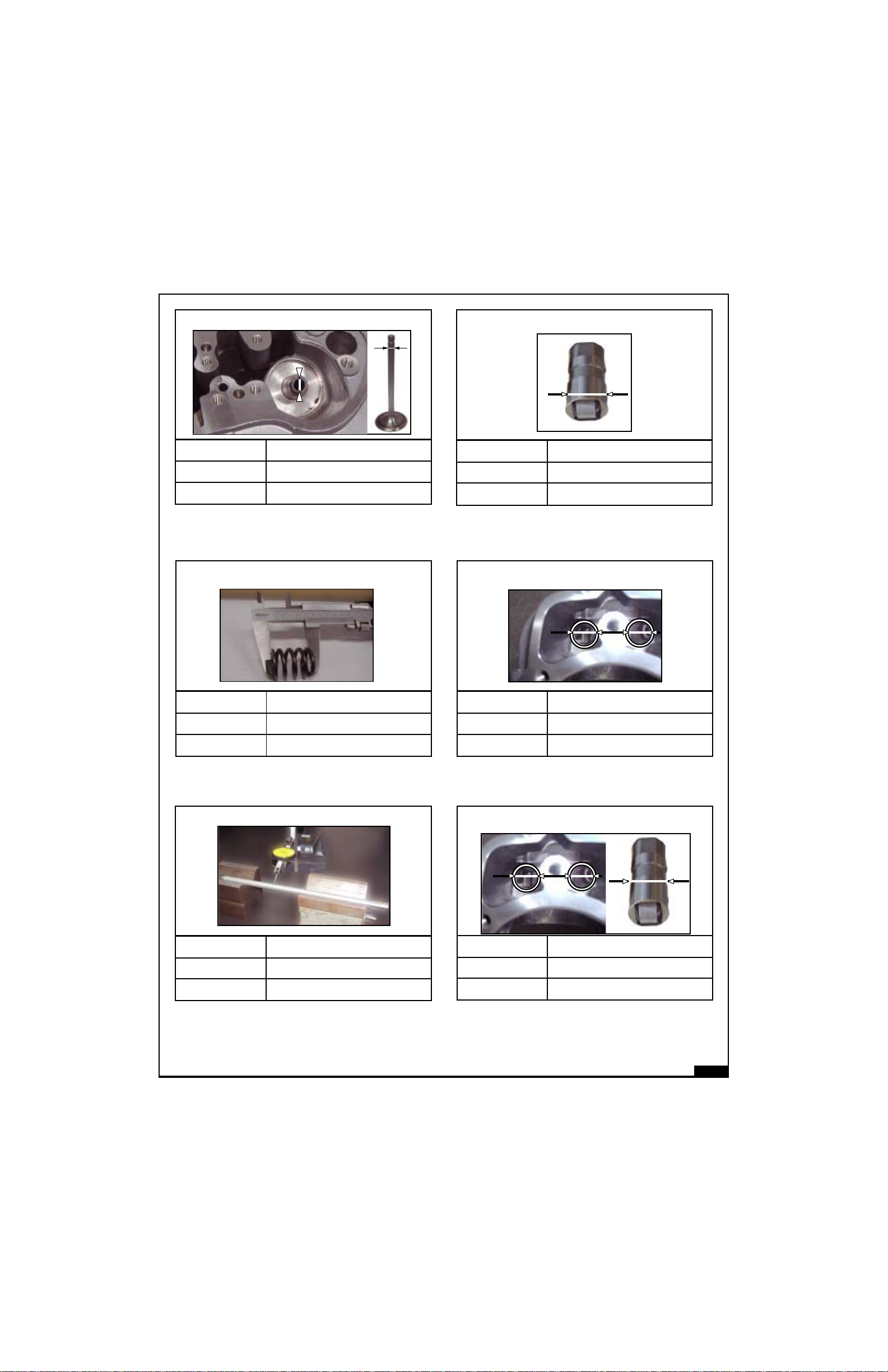
New Min.
New Max.
Service Limit
Valve to guide (Exhaust) Clearance
0.04
0.07
1.00
New Min.
New Max.
Service Limit
Hydraulic Tappet OD
21.387
21.405
21.380
New Min.
New Max.
Service Limit
Valve Spring : length
42.80
44.80
41.50
New Min.
New Max.
Service Limit
21.417
21.438
21.450
Hydraulic Tappet guide bore
New Min.
New Max.
Service Limit
Push rod run out
0.00
0.02
0.05
New Min.
New Max.
Service Limit
0.012
0.051
0.060
Hydraulic tappet to guide clearance
 Loading...