

Page 1
Bullet Classic EFI (C5)
Bullet Electra EFI (E5)
Bullet EFI (G5)
Page 2

SECTIONSECTION
SECTION
SECTIONSECTION
ONE 01ONE 01
ONE 01
ONE 01ONE 01
INTRODUCTIONINTRODUCTION
INTRODUCTION
INTRODUCTIONINTRODUCTION
Page 3

PREFPREF
PREF
PREFPREF
We are pleased to release this workshop manual for the new generation of Royal Enfield
Motorcycles fitted with unit construction engine, electronically controlled “Engine Management
System” and fuel injection technology.
We have endeavoured to make this manual user friendly. However, we welcome your valuable
suggestions for improvements which you may write to us or email us at vvikram@royalenfield.com.
Service Head Quarters,
Royal Enfield
Chennai.
AA
A
AA
CECE
CE
CECE
“ © Copyright 2009 EICHER MOTORS LIMITED, UNIT ROYAL ENFIELD.
All Rights Reserved. No part of this Service technical manual shall be copied,
distributed or otherwise dealt, without the express permission in written from Eicher
Motors Limited, Unit Royal Enfield, who remains the sole owner of this manual .”
Part No. 597451 / Qty. 500 / May ‘09
01-1
Page 4

FOREWFOREW
FOREW
FOREWFOREW
ORDORD
ORD
ORDORD
PREPARATION FOR SERVICE
Good preparation is very important for carrying out correct service job. The motorcycle should be
cleaned well before starting a repair job. Cleaning will occasionally uncover sources of trouble.
Availability of tools, measuring instruments and parts should be ensured before commensing an
overhaul, since Interruption to locate tools or parts can cause distraction and needless delay. Use of
special tools will ensure a quality service.
USE OF GENUINE SPARE PARTS
Use only genuine Royal Enfield spares whenever replacing parts. Use of non genuine parts can
seriously affect motorcycle performance and may result in costly rework, vehicle down time and
above all customer dissatisfaction.
NOTE :
Proper service and repair is important for the safe and reliable operation of all mechanical products.
The service procedures recommended and detailed in this manual will help to carry out correct repairs.
SAFETY
Every care is taken to ensure that the information given in this manual is correct at the time of going to
print. However, Royal Enfield does not assume responsibility for any damage, loss or injury caused to
the vehicle or to the person carrying out repairs, due to errors or omissions in this manual.
IMPORTANT NOTICE
All images shown are only for reference to explain and may not be exactly the same on the motorcycle.
Technical specifications are subject to change without prior notice.
Because of changes that may occur in the manufacturing process, since this manual was printed, it
is possible some instructions or illustrations found within this manual may differ from those found on
the vehicle. However the technical information found within this manual is correct at the time, when it
was approved for printing.
Future modifications, improvements etc will be communicated to our Authorised Distributors / Importers
as and when changes are done to the motorcycle.
01-2
Page 5

HOHO
W W
TT
HO
W
HOHO
W W
SERSER
SER
SERSER
Pictorial presentation of various activities, make
this manual easy to understand and user friendly.
This service manual is divided into 10 Sections
01 to 10. Page numbers for each section starts
with 01. Thus, page 05-10 indicates 10th page
of section 5.
O USE O USE
T
O USE
TT
O USE O USE
VICE MANUVICE MANU
VICE MANU
VICE MANUVICE MANU
YY
OUROUR
Y
OUR
YY
OUROUR
ALAL
AL
ALAL
Engine breather System
Clutch System
Inlet manifold & Throttle body
Blow up Charts.
SECTION FIVE 05SECTION FIVE 05
SECTION FIVE 05
SECTION FIVE 05SECTION FIVE 05
ENGINE DISMANTLINGENGINE DISMANTLING
ENGINE DISMANTLING
ENGINE DISMANTLINGENGINE DISMANTLING
INSPECTION & INSPECTION &
INSPECTION &
INSPECTION & INSPECTION &
Torque Specification - Engine
ASSEMBLASSEMBL
ASSEMBL
ASSEMBLASSEMBL
YY
Y
YY
The sections are subdivided into subjects and
presented in the following order.
SECTION ONE O1SECTION ONE O1
SECTION ONE O1
SECTION ONE O1SECTION ONE O1
INTRODUCTIONINTRODUCTION
INTRODUCTION
INTRODUCTIONINTRODUCTION
The manual and its arrangements
SECTION TWO 02SECTION TWO 02
SECTION TWO 02
SECTION TWO 02SECTION TWO 02
GENERALGENERAL
GENERAL
GENERALGENERAL
Salient features of the Unit construction engine
& engine management system
Four stroke cycle operation
Basic terminology of automobiles
Technical specifications
Identification of Chassis No., Engine No.,
List of special tools and its applications
Control cables and wiring harness routing.
SECTION THREE 03SECTION THREE 03
SECTION THREE 03
SECTION THREE 03SECTION THREE 03
SERSER
SER
SERSER
VICE DVICE D
VICE D
VICE DVICE D
AA
A
AA
TT
T
TT
AA
A
AA
Engine dismantling procedure
Vital parts - Description
Unidirectional fittings list
Engine assembling procedure
SECTION SIX 06SECTION SIX 06
SECTION SIX 06
SECTION SIX 06SECTION SIX 06
ENGINE MANENGINE MAN
ENGINE MAN
ENGINE MANENGINE MAN
SYSY
STEMSTEM
SY
STEM
SYSY
STEMSTEM
Functional Diagram
Components description
Function of components
Identification of a malfunction in EMS
Do’s & Dont’s
Trouble shooting
SECTION SEVEN 07SECTION SEVEN 07
SECTION SEVEN 07
SECTION SEVEN 07SECTION SEVEN 07
WHEELS & BRAKESWHEELS & BRAKES
WHEELS & BRAKES
WHEELS & BRAKESWHEELS & BRAKES
Torque Specification - Chassis
Front wheel removal & reassembly
AA
GEMENTGEMENT
A
GEMENT
AA
GEMENTGEMENT
Service limits of components
Periodical maintenance chart
SECTION FOUR 04SECTION FOUR 04
SECTION FOUR 04
SECTION FOUR 04SECTION FOUR 04
ENGINEENGINE
ENGINE
ENGINEENGINE
Lubrication system
Roller hydraulic Valve lifter (RHVL)
Auto decompressor
Electric starter system & sprag mechanism
Auto Chain Tensioner Assembly
Disc brake
- General instruction
- Master Cylinder & Caliper overhauling
- Bleeding procedure
- Disc inspection
Rear wheel removal & reassembly
Rear Brake removal & reassembly
01-3
Page 6

SECTION EIGHT 08SECTION EIGHT 08
SECTION EIGHT 08
SECTION EIGHT 08SECTION EIGHT 08
SUSPENSION ANDSUSPENSION AND
SUSPENSION AND
SUSPENSION ANDSUSPENSION AND
STEERINGSTEERING
STEERING
STEERINGSTEERING
- Relay starter
- Starter motor
- IC Flasher
Front fork working principle
Front fork removal & reassembly
Steering stem removal & reassembly
Gas filled shock absorber
- Working principle
- Removal and assembly
- Adjustment of shock absorber
- Recharging of shock absorber
Swing Arm
- Removal
- Bush lubrication / replacement
- Reassembly
Centre Stand Removal & Reassembly
SECTION NINE 9SECTION NINE 9
SECTION NINE 9
SECTION NINE 9SECTION NINE 9
ELECTRICALSELECTRICALS
ELECTRICALS
ELECTRICALSELECTRICALS
Electrical symbols
Battery
- Precautions
- Charging
- RR Unit
- TPS Unit
Electrical parts Inspection
- Clutch switch
- Starter switch
- Switch modules LH & RH
Do’s and Dont’s
Wiring Diagrams
- Ignition circuit
- Starter and charging
- Complete Wiring diagram
Trouble shooting
SECTION TEN 10SECTION TEN 10
SECTION TEN 10
SECTION TEN 10SECTION TEN 10
TRTR
OUBLE SHOOOUBLE SHOO
TR
OUBLE SHOO
TRTR
OUBLE SHOOOUBLE SHOO
SAFETY DEFINITIONSSAFETY DEFINITIONS
SAFETY DEFINITIONS
SAFETY DEFINITIONSSAFETY DEFINITIONS
Important aspects to be noted are given as
follows in the manual.
TINGTING
TING
TINGTING
- Maintenance
Spark plug maintenance & Inspecton
Checking procedure of electrical
components:
- Starter coil
- Pulsar coil
- Ignition coil
- Suppressor Cap
- Battery
- Horn
NOTE
Provides important information that will have to
be adhered to while carrying out repairs.
CAUTION
Indicates activities that are important to be
noted. Non-adherance may result in breakage
and or functional failures of the assembly.
SPECIAL TOOLS
Contains details of the special tools and its
usage, These tools have been specially designed
for a specific purpose.
01-4
Page 7

SECTIONSECTION
SECTION
SECTIONSECTION
TWO 02TWO 02
TWO 02
TWO 02TWO 02
GENERALGENERAL
GENERAL
GENERALGENERAL
Page 8
SALIENT FEASALIENT FEA
SALIENT FEA
SALIENT FEASALIENT FEA
ENGINE & ENGINE MANENGINE & ENGINE MAN
ENGINE & ENGINE MAN
ENGINE & ENGINE MANENGINE & ENGINE MAN
TURES OF TURES OF
TURES OF
TURES OF TURES OF
THE UNIT CONSTRTHE UNIT CONSTR
THE UNIT CONSTR
THE UNIT CONSTRTHE UNIT CONSTR
AA
GEMENT SYGEMENT SY
A
GEMENT SY
AA
GEMENT SYGEMENT SY
STEMSTEM
STEM
STEMSTEM
UCTIONUCTION
UCTION
UCTIONUCTION
• HIGH TORQUE ENGINE
• ENHANCED POWER DELIVERY
• HYDRAULIC TAPPETS
• AUTO DECOMPRESSOR
• AUTO CHAIN TENSIONER FOR
PRIMARY CHAIN
• HIGH CAPACITY TRACHOIDAL OIL
PUMP FOR BETTER LUBRICATION
FOUR STRFOUR STR
FOUR STR
FOUR STRFOUR STR
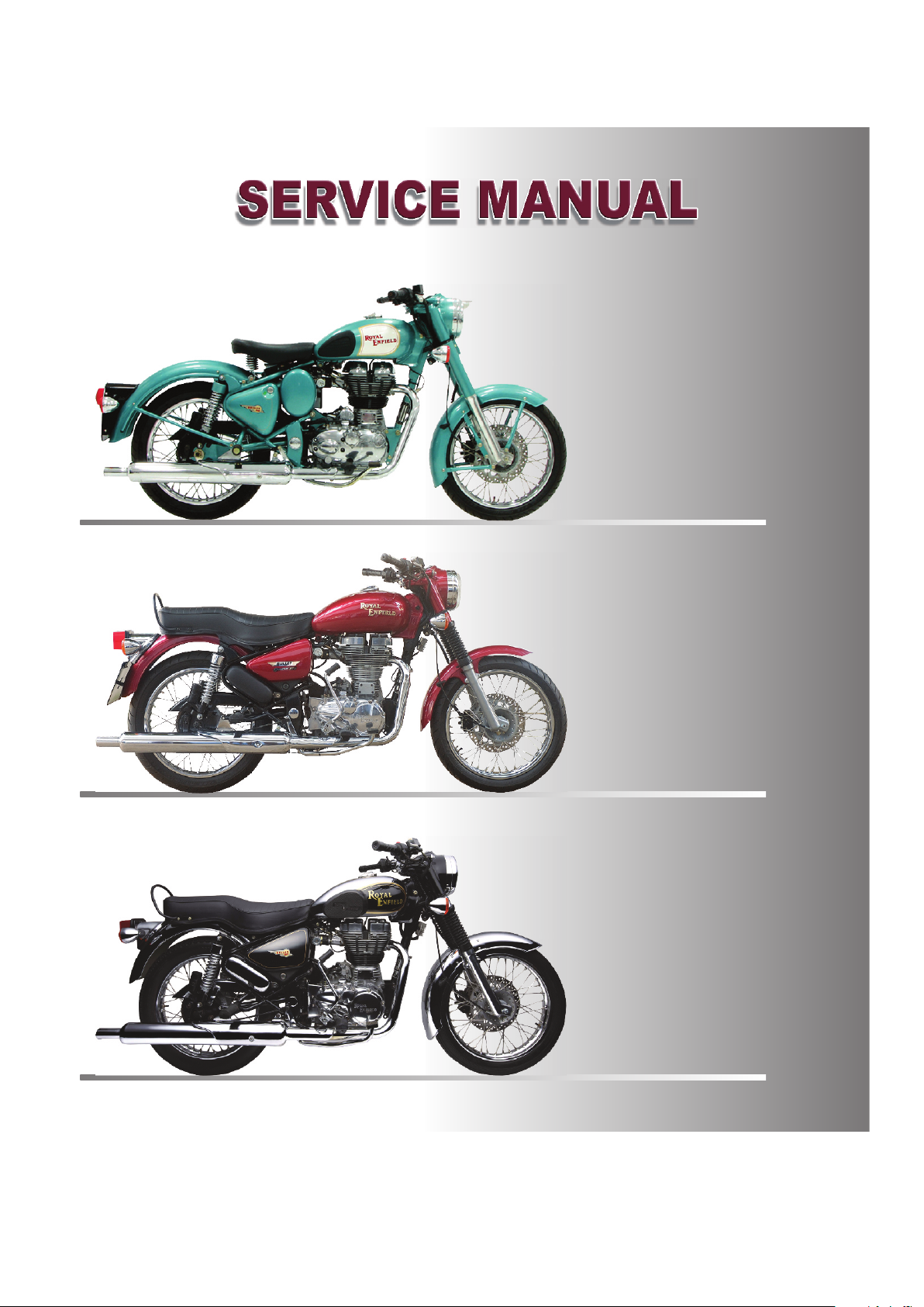
SUCTION COMPRESSION POWER EXHAUST
STROKE
Inlet Valve Open Closed Closed Closed
OKE CYOKE CY
OKE CY
OKE CYOKE CY
STROKE STROKE STROKE
• IMPROVED ACCELERATION & HIGH
SPEED CRUISING
• EXCELLENT COLD STARTING
ABILITY
• ACCURATELY CONTROLLED, AIR
FUEL MIXTURE & IGNITION TIMING
BY THE ENGINE CONTROL UNIT
• IMPROVED PERFORMANCE AND
FUEL EFFICIENCY THRO FUEL
INJECTION SYSTEM.
CLE OPERACLE OPERA
CLE OPERA
CLE OPERACLE OPERA
TIONTION
TION
TIONTION
Exhaust Valve Closed Closed Closed Open
Piston Movement TDC to BDC BDC to TDC TDC to BDC BDC to TDC
Gas Flow Air Petrol Air Petrol Air petrol mixture Exhaust gas
mixture is mixture gets burns, gas
expands. flows out.
drawn into compressed. Piston is
cylinder Few degrees before pushed down.
BTDC, spark plug
produces spark.
02-1
Page 9
BASIC BASIC
BASIC
BASIC BASIC
TERMINOLTERMINOL
TERMINOL
TERMINOLTERMINOL
OGY OF OGY OF
OGY OF
OGY OF OGY OF
ENGINE :
The Engine helps to convert Chemical energy
availbale in petrol into heat energy then to
mechanical energy for motion. It is the heart of
the vehicle in which power is generated for
moving the vehicle.
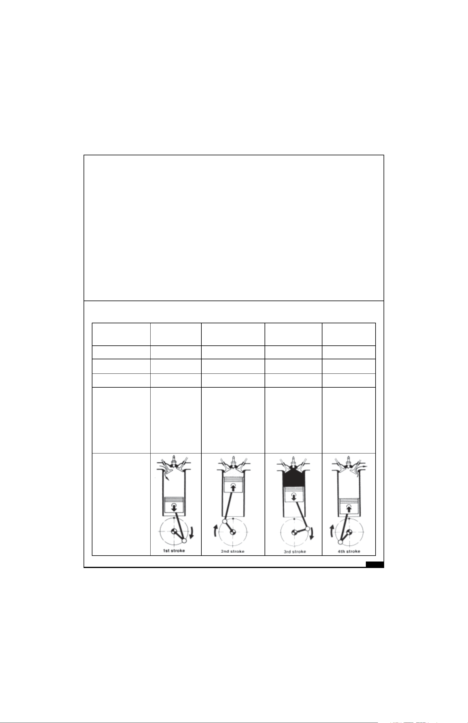
BORE :
Bore is the inside diameter of the cyclinder block
in which Piston moves up and down.
TDC :
TDC stands for Top Dead Center. It is the top
most position to which the piston can travel in
the cylinder barrel.
BDC :
AUTAUT
AUT
AUTAUT
Fuel
Air
OMOBILESOMOBILES
OMOBILES
OMOBILESOMOBILES
Power
BDC stands for Bottom Dead Center. It is the
bottom most position to which the piston can
travel in the cylinder barrel.
STROKE :
It is a distance travelled by piston from TDC to
BDC or Vice Versa.
CUBIC CAPACITY / DISPLACEMENT :
It is a volume generated by piston when it travels from TDC to BDC. It is measured as Cubic Centimeter
(CC). It can be mathematically arrived at with the radious of the piston and the stroke of the engine.
(πr²× l, when ‘r’ is the radius of the piston and ‘l’ is the length of the stroke). It is also known as Swept
Volume or Displacement volume.
CLEARANCE VOLUME :
It is the nominal volume of the space above the
piston in the combustion chamber when piston
is at the topmost position (TDC).
02-2
Page 10

TOTAL VOLUME :
It is the sum of the swept voume (Displacement volume) and Clearance volume.
Total Volume = Swept volume + Clerance volume.
COMPRESSION RATIO :
It is a ratio between total volume in the engine to the clearance volume available at the end of
compression stroke.
Compression ratio =
Total volume of air fuel mixture
Clearance volume
VOLUMETRIC EFFICIENCY :
Volumetric efficiency is the ratio between the volume of air fuel mixture that actually enters the cylinder
and Swept volume.
Volumetric Efficiency
= Volume of air fuel mixture inhaled during suction stroke
Swept volume
HORSE POWER (HP OR PS) :
HP : Horse Power
PS : PFERDESTARKE is German unit of power. Horse Power is the ability of the engine to do a
certain amount of work in a given time.
One Horse power is the power required for lifting a weight of 75 Kg. through vertical distance of one
meter in one second.
Conversion :
1PS = 0.986 HP = 0.735 KW
1 HP = 1.014 PS = 0.744 KW
1KW = 1.360 PS = 1.340 HP
02-3
Page 11
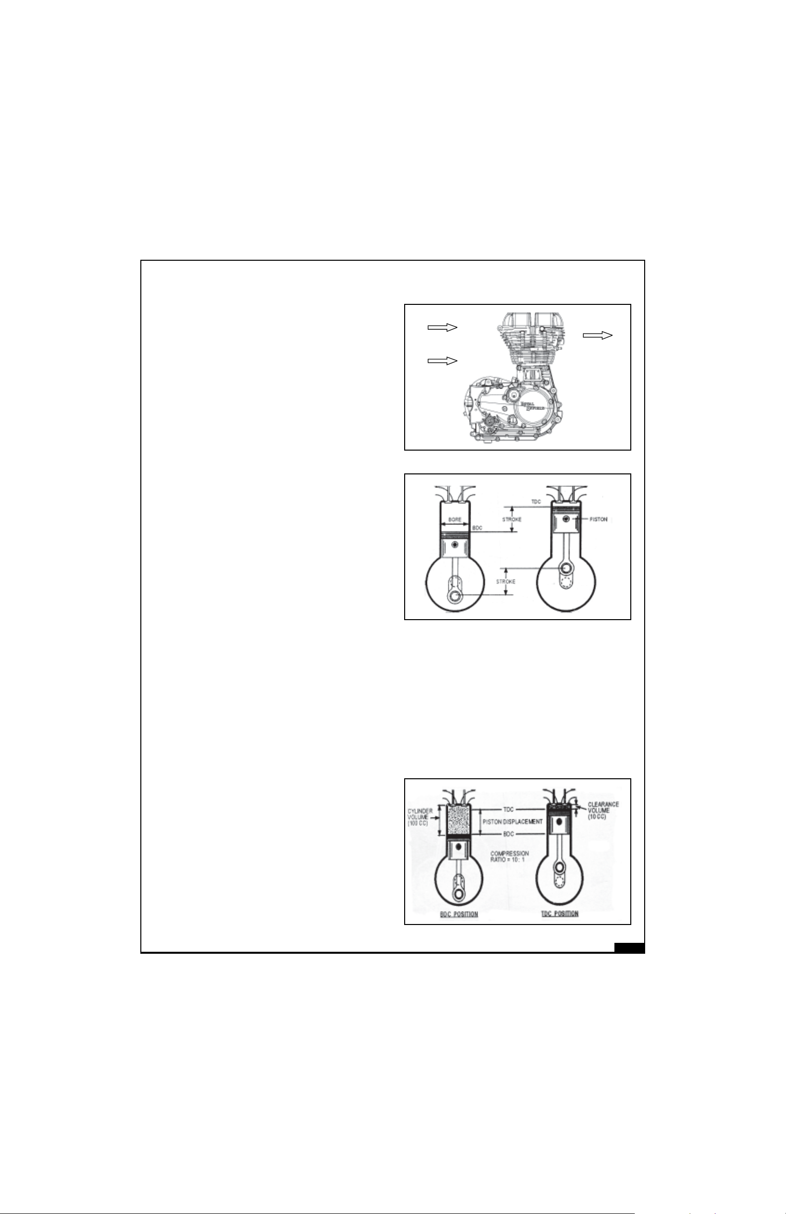
IHP :
IHP stands for Indicated Horse Power. Indicated
Horse Power is the power actually developed
inside the engine cylinder by combustion process.
It is utilised to drive the piston.
1HP (Horse
Power Available
after explosion)
FHP :
FHP (Frictional
Losses)
FHP stands for Frictionl Horse Power.
It is the amount of horse power used or lost to
overcome the friction between various engine
components.
BHP :
BHP stands for Brake Horse Power
BHP (Horse
Power Avaiable at
Crankshaft)
Brake Horse Power is the amount of Power actually available at the crankshaft or output shaft. It
is calculated by using dynamometer.
BHP = IHP - FHP
MECHANICAL EFFICIENCY :
Mechanical Efficiency is the ratio between Brake horsepower and Indicated horse power.
Brake horsepower = BHP
Indicated Horse power IHP
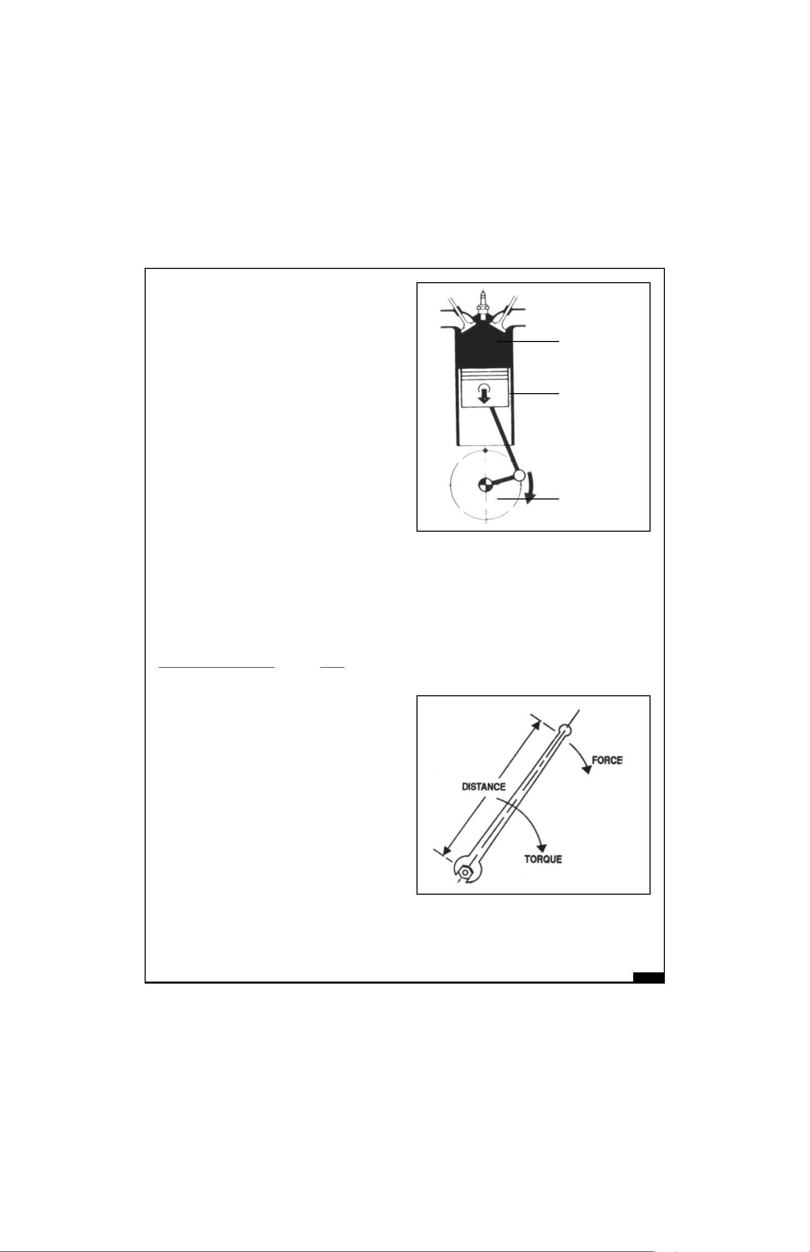
TORQUE :
Torque is a twisting or turning force or effort. It is the
product of a distance and force in circular motion.
In the picture shown the torque-applied is the product
of distance (distance between the center of the bolt
and point where force is acting) and the amount of
force applied.
With the same force, if the distance is increased,
the torque will also increase and if distance is
reduced, torque applied will also be reduced.
CONVERSION :
1kg-m = 7.23 lb.ft = 9.81 N-m.
1lb.ft = 0.138 Kg-m = 1.356 N-m.
1 N-m = 0.102 Kg-m = 0.737 lb.ft
02-4
Page 12
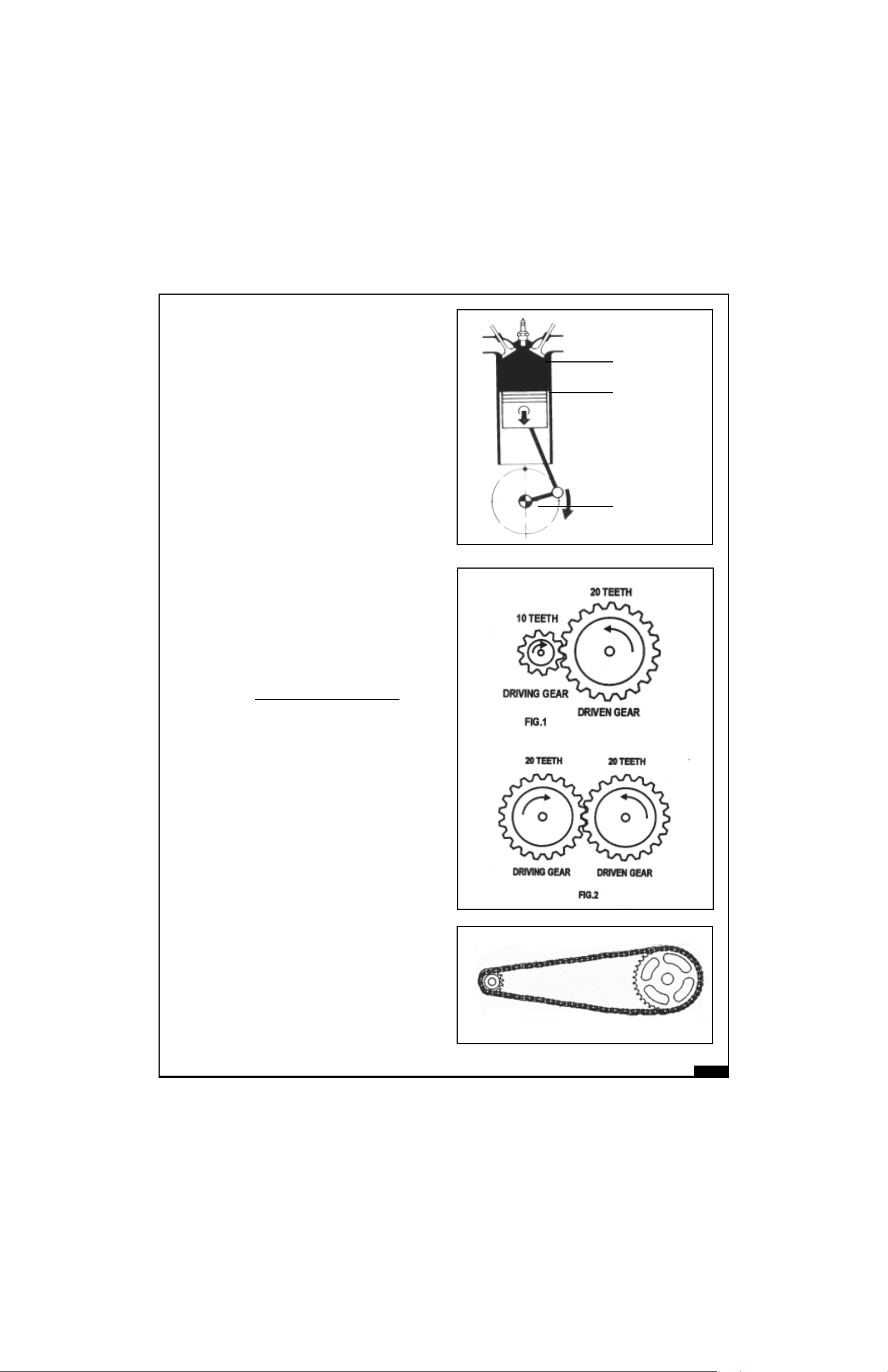
IGNITION TIMING :
Ignition timing is the timing at which spark
commences so that the spark from the spark
plug can ignite the mixture in the combusion
chamber at the end of TDC during compression
stroke.
If spark occurs earlier than specified ignition
timing, it is called “Advance” timing.
If spark occurs after the specified ignition timing,
it is called “Retard” timing.
IDLING SPEED :
It is the speed of the crankshaft (i.e. RPM) of the
engine when the throttle is in closed pisition.
GEAR RATIO :
The relative rotation between “Driven Gear” and
“Driving Gear” is known as the “Gear Ratio”. It is
determined by number of teeth on the respective
gears.
TDC Position
Ignition Timing
Position
Ignition Timing in
Degrees
Gear Ratio =
No. of teeth of Driven Gear
No. of teeth of Driving Gear
In Fig. 1, the Gear ratio is 20 ÷ 10 = 2 : 1
In Fig. 2, the Gear ratio is 20 ÷ 20 = 1 : 1
Gear ratios multiply the engine torque to fulfil
various demands for pulling the vehicle like.
- More effort is required during initial
movement of the vehicle.
- More effort is required to climb an elevation.
- More effort is required while driving in
muddy or sandy surfaces.
FINAL DRIVE RATIO :
It is a relative rotation between the engine
sprocket and the sprocket on the rear wheel.
Both the sprockets are connected through drive
chain.
Final drive ratio further multiplies the torque
available at the output shaft.
02-5
Page 13

TECHNICAL SPECIFICATECHNICAL SPECIFICA
TECHNICAL SPECIFICA
TECHNICAL SPECIFICATECHNICAL SPECIFICA
TIONSTIONS
TIONS
TIONSTIONS
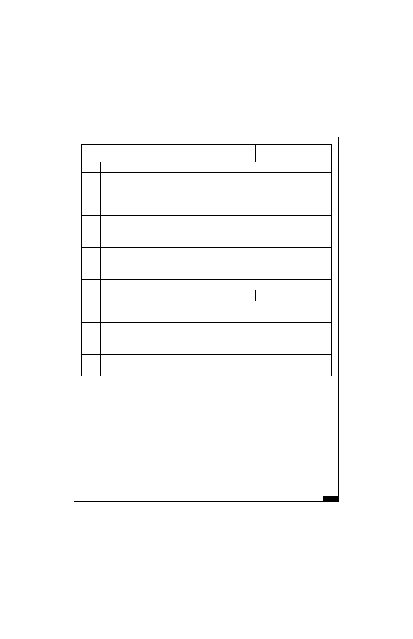
A. ENGINE AND ENGINE SYSTEMS
BULLET ELECTRA EFI (E5) BULLET CLASSIC EFI
BULLET EFI (G5) (C5)
1. Engine Type 4 Stroke Single Cylinder, Air cooled
2. Bore 84mm
3. Stroke 90mm
4. Displacement 499cc
5. Compression ratio 8.5:1
6. Max Power @ rpm 20.3 Kw @ 5250 rpm
7. Max Torque @ rpm 41.3 Nm @ 4500 rpm
8. Idle rpm 1050 ± 200 rpm
9. Starting Kick & Electric Start Electric Start
10. Air filter element Paper element
11. Lubrication Forced Lubrication, Wet Sump
12. Engine oil tank capacity 2.75 litres
13. Engine oil grade
JASO MA -15W-50, API SL Grade,
ESTER-Semi Synthetic Oil
14. Cooling Natural air flow
B. TRANSMISSION
1. Clutch Wet multiplate
2. Primary drive 3/8” Duplex chain & sprocket
3. Primary ratio 2.15 : 1
4. Gear box 5 Speed Constant Mesh
5. Overall Ratio
st
1
nd
2
rd
3
th
4
th
5
6. Secondary drive 5/8” Chain & Sprocket
3.063 : 1
2.013 : 1
1.522 : 1
1.212 : 1
1 : 1
7. Secondary ratio 2.235 : 1 2.11:1
8. Drive Chain links 101 Pitch 102 Pitch
02-6
Page 14

C. CHASSIS
BULLET ELECTRA EFI (E5) BULLET CLASSIC EFI
BULLET EFI (G5) (C5)
1. Frame Tubular
2. Front Suspension Telescopic, hydraulic damping, Stroke 130 mm
3. Rear Suspension Swing arm with gas shock absorbers
4. Fr. Fork oil capacity 265 cc + 2.5 cc / each leg
5. Front fork oil SAE 10W -30
6. Front Brake Hydraulic, Hand operated, 280 mm dia ventilated disc
7. Rear Brake Mechanical, Foot operated, 153 mm internal expanding
8. Brake Oil Capacity 60 ml
9. Brake Oil Grade DOT 3 or DOT 4
10. Tyre size : Front 90X90 - 19” - 51V 90X90 - 18” 51V
3.25X19
Rear 100/90 - 19” - 57V 110/80-18” - 58V
3.5X90
D. TYRE PRESSURE
1. Solo : Front 18 PSI
Rear 28 PSI
2. With Pillion : Front 20 PSI
Rear 30 PSI
3. Steering lock In built
4. Fuel tank capacity 14.5 ±1 litres
5. Reserve 2.75 litres
E. ELECTRICALS
1. Generation Alternator
2. System 12V - DC
3. Battery 12V - 14 AH
4. Spark plug Mico - WR7 DDC 4
5. Spark plug gap 0.7 to 0.8 mm
6. Head lamp 12V, 60/55w
02-7
Page 15
BULLET ELECTRA EFI (E5) BULLET CLASSIC EFI
BULLET EFI (G5) (C5)
7. Tail / Brake Lamp 12V 5 / 21W
8. Speedometer lamp 12V, 3.4W
9. Hi beam indicator 12V, 2W
10. Neutral lamp Tell tale 12V, 2W
11. Turn Signal Tell Tale 12V, 2W
12. Turn signal 12V, 10W
13. Horn 12V DC
F. WEIGHTS
1. Mass of Vehicle in running order 187 Kg.
2. Max pay load 178 Kgs.
3. Max technical permissible mass 365 Kg.
G. DIMENSIONS
1. Length 2200 mm 2160 mm
2. Width 800 mm
3. Height 1100 mm 1050 mm
4. Wheel base 1370 mm
5. Ground clearance 140 mm
6. Saddle height 820 mm 800 mm
H. PERFORMANCE
1. Max. speed 132 Kmph (83 Miles)
NOTE :
1. Values given above are for your guidelines only
2. In view of continuous improvements, specifications are likely to change without
notice
02-8
Page 16
IDENTIFICAIDENTIFICA
IDENTIFICA
IDENTIFICAIDENTIFICA
TION OF CHASSIS NOTION OF CHASSIS NO
TION OF CHASSIS NO
TION OF CHASSIS NOTION OF CHASSIS NO
.,.,
ENGINE NO ENGINE NO
.,
ENGINE NO
.,.,
ENGINE NO ENGINE NO
,,
,
,,
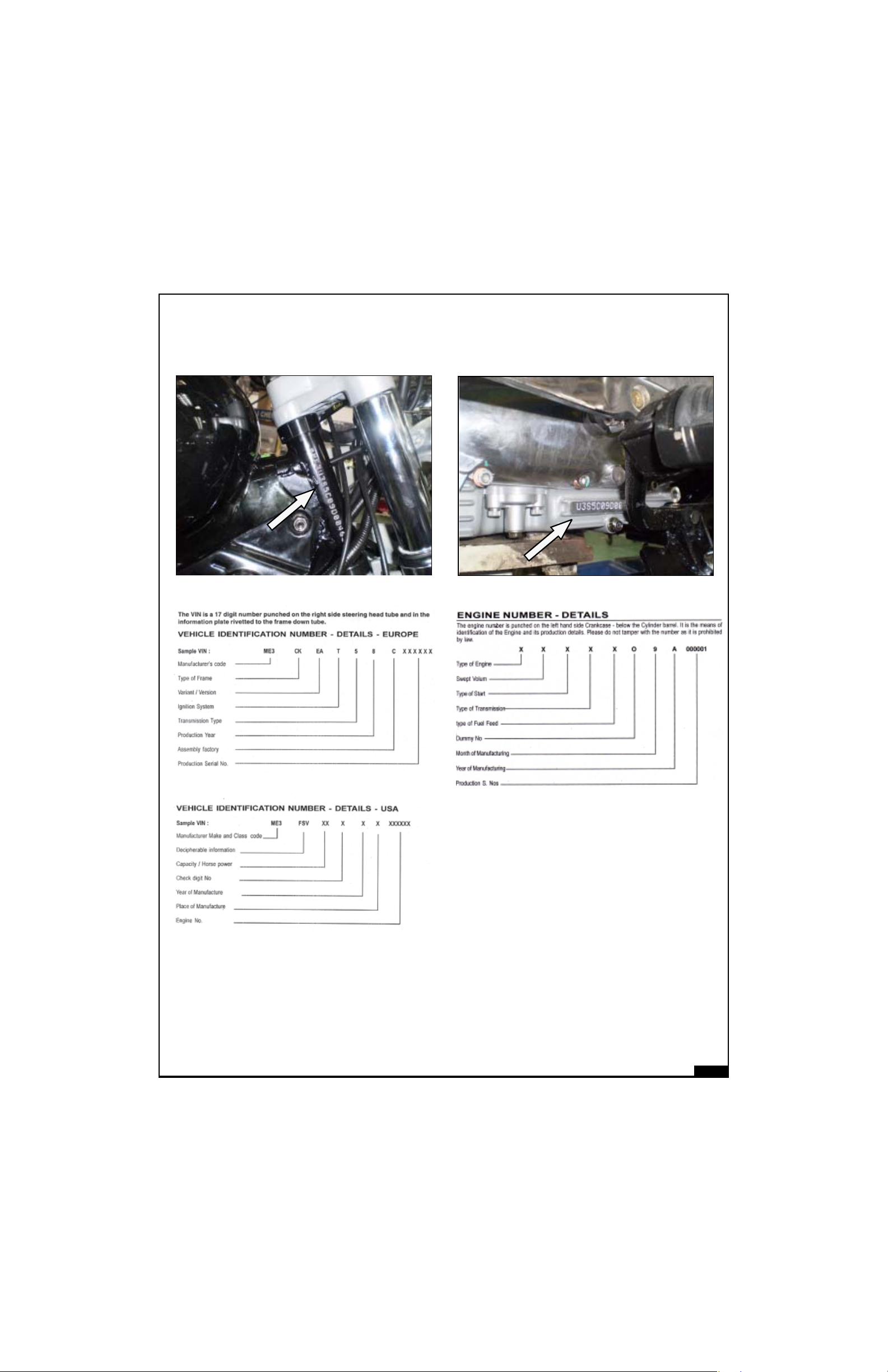
CHASSIS NO.
ENGINENO.
02-9
Page 17
LIST OF SPECIAL LIST OF SPECIAL
LIST OF SPECIAL
LIST OF SPECIAL LIST OF SPECIAL
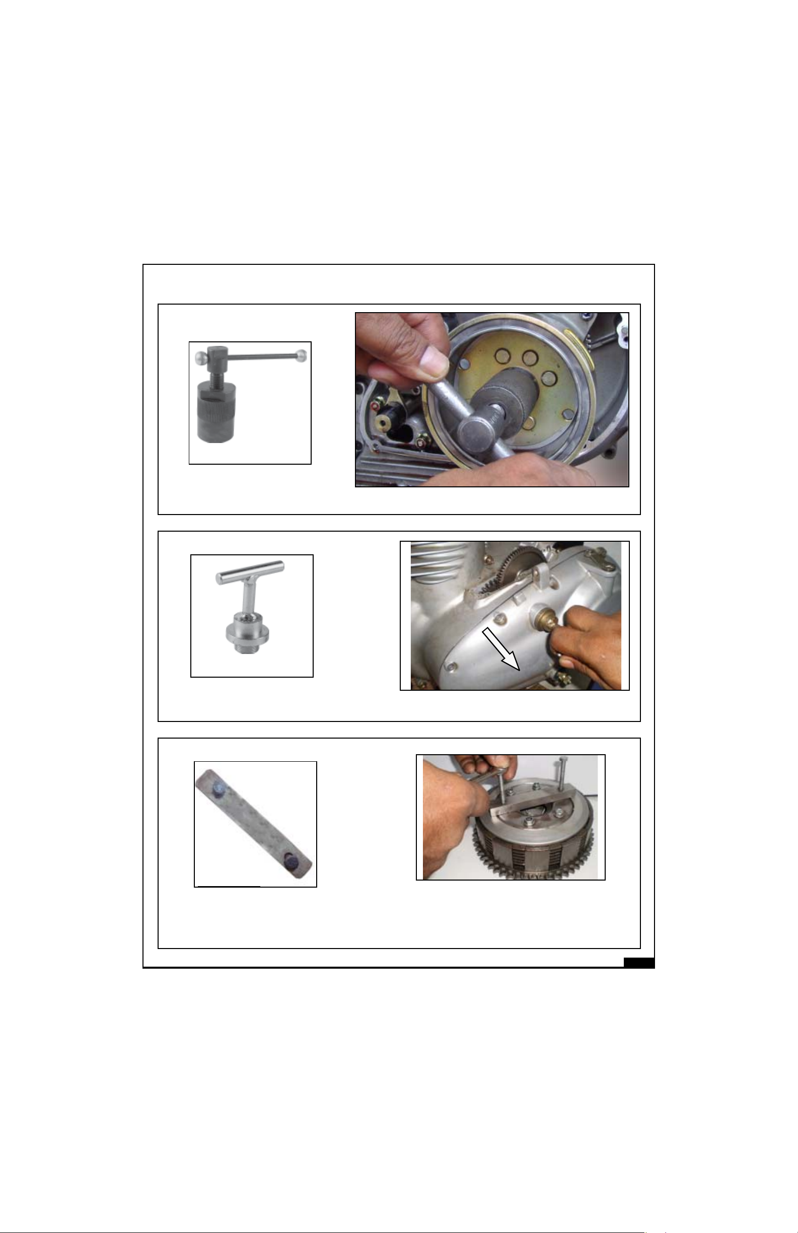
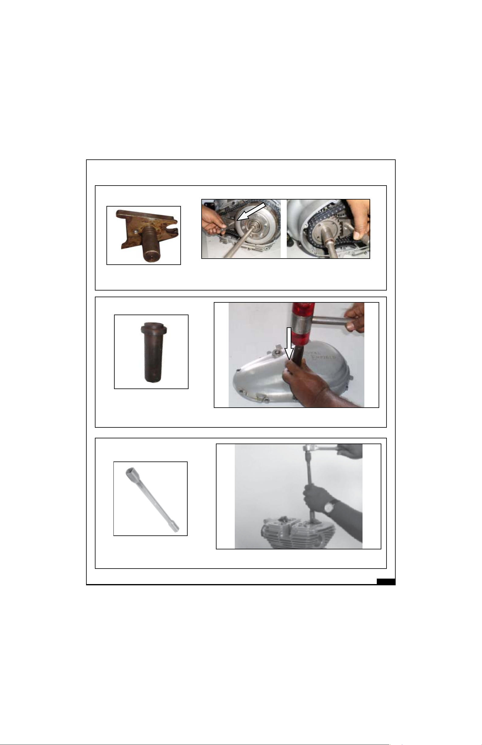
ST 25128-2
Magneto Puller for TCI
TT
OOLS OOLS
T
OOLS
TT
OOLS OOLS
Application : Removal of magneto assembly
AND ITS AND ITS
AND ITS
AND ITS AND ITS
APPLICAAPPLICA
APPLICA
APPLICAAPPLICA
TIONTION
TION
TIONTION
ST 25151-4
Chain case outer puller (TCI)
ST-25594-4
Clutch spring assy.
Application :To remove Crank case LH cover
Application : To compress clutch springs while
removing & refitting Clutch plates.
02-10
Page 18
LIST OF SPECIAL LIST OF SPECIAL
LIST OF SPECIAL
LIST OF SPECIAL LIST OF SPECIAL
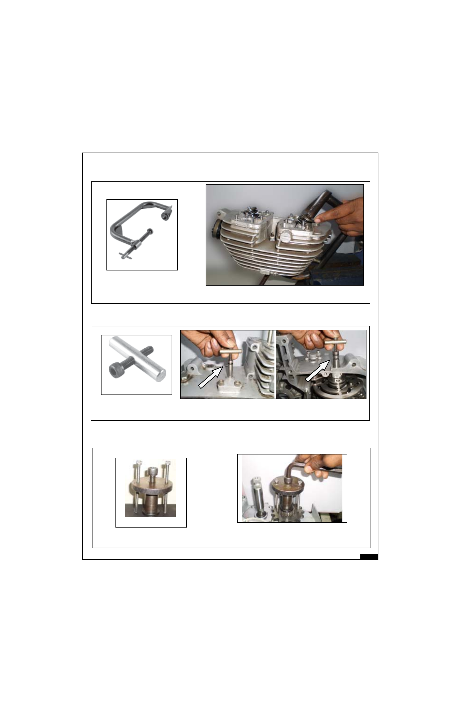
ST-25591-4
Clutch centre nut
TT
OOLS OOLS
T
OOLS
TT
OOLS OOLS
Application : To hold Clutch Sprocket while removing / tightening
the Clutch & Sprag Sprocket Nut.
AND ITS AND ITS
AND ITS
AND ITS AND ITS
APPLICAAPPLICA
APPLICA
APPLICAAPPLICA
TIONTION
TION
TIONTION
Oil seal adopter
ST 25118-4
Cylinder head nut tightening tool
Application : Fitment of gear shaft oil seal on crank case
LH cover.
Application : To remove and tightening of cylinder
head nut.
02-11
Page 19
LIST OF SPECIAL LIST OF SPECIAL
LIST OF SPECIAL
LIST OF SPECIAL LIST OF SPECIAL
ST 25123-1
Valve Spring compressor
TT
OOLS OOLS
T
OOLS
TT
OOLS OOLS
Application : To compress the valve spring for removal
AND ITS AND ITS
AND ITS
AND ITS AND ITS
and fitting of valve.
APPLICAAPPLICA
APPLICA
APPLICAAPPLICA
TIONTION
TION
TIONTION
ST 25153-4
Extractor for 5 Speed
Gear box Pivot Pin
ST 25
FD sprocket removal tool
Application : To remove Gear Rocker Shaft top pivot pin and Gear
Cam Plate pivot pin.
Application : To remove front drive sprocket
from Sleeve Gear.
02-12
Page 20
LIST OF SPECIAL LIST OF SPECIAL
LIST OF SPECIAL
LIST OF SPECIAL LIST OF SPECIAL
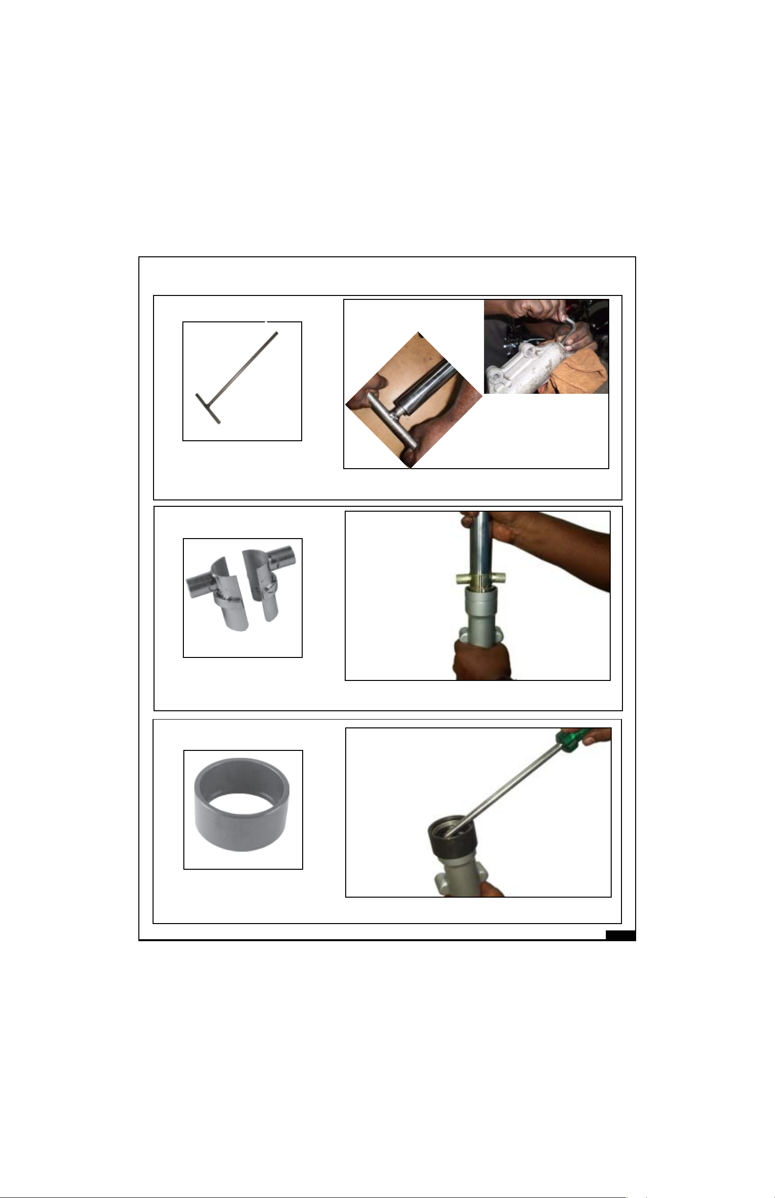
ST
Front fork main tube spanner
TT
OOLS OOLS
T
OOLS
TT
OOLS OOLS
Application : Loosening and tightening of front fork main
AND ITS AND ITS
AND ITS
AND ITS AND ITS
tube with fork end
APPLICAAPPLICA
APPLICA
APPLICAAPPLICA
TIONTION
TION
TIONTION
ST 25112-4
Expander for front fork oil seal
ST 25114-4
Extractor for Fork oil seal
Application : Expander for oil seal while inserting main
tube into bottom tube of front fork
Application : Removal of oil seal in front fork bottom tube
02-13
Page 21
LIST OF SPECIAL LIST OF SPECIAL
LIST OF SPECIAL
LIST OF SPECIAL LIST OF SPECIAL
ST 25113-4
Mandrel for oil seal
TT
OOLS OOLS
T
OOLS
TT
OOLS OOLS
Application : Fitment of oil seal in front fork bottom tube
AND ITS AND ITS
AND ITS
AND ITS AND ITS
APPLICAAPPLICA
APPLICA
APPLICAAPPLICA
TIONTION
TION
TIONTION
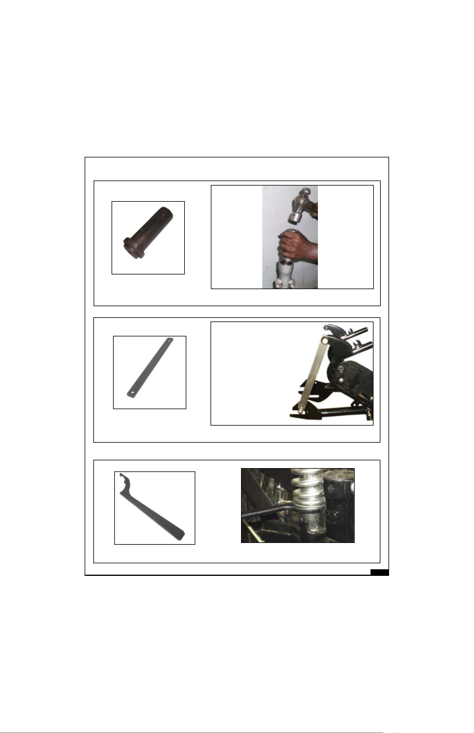
ST 25110-3
Gauge for tightening chain stay
ST 25244-4
Adjuster Special Spanner
Application : Alignment of Swing Arm while tightening
Application :To adjust gas filled shock absorber
02-14
Page 22
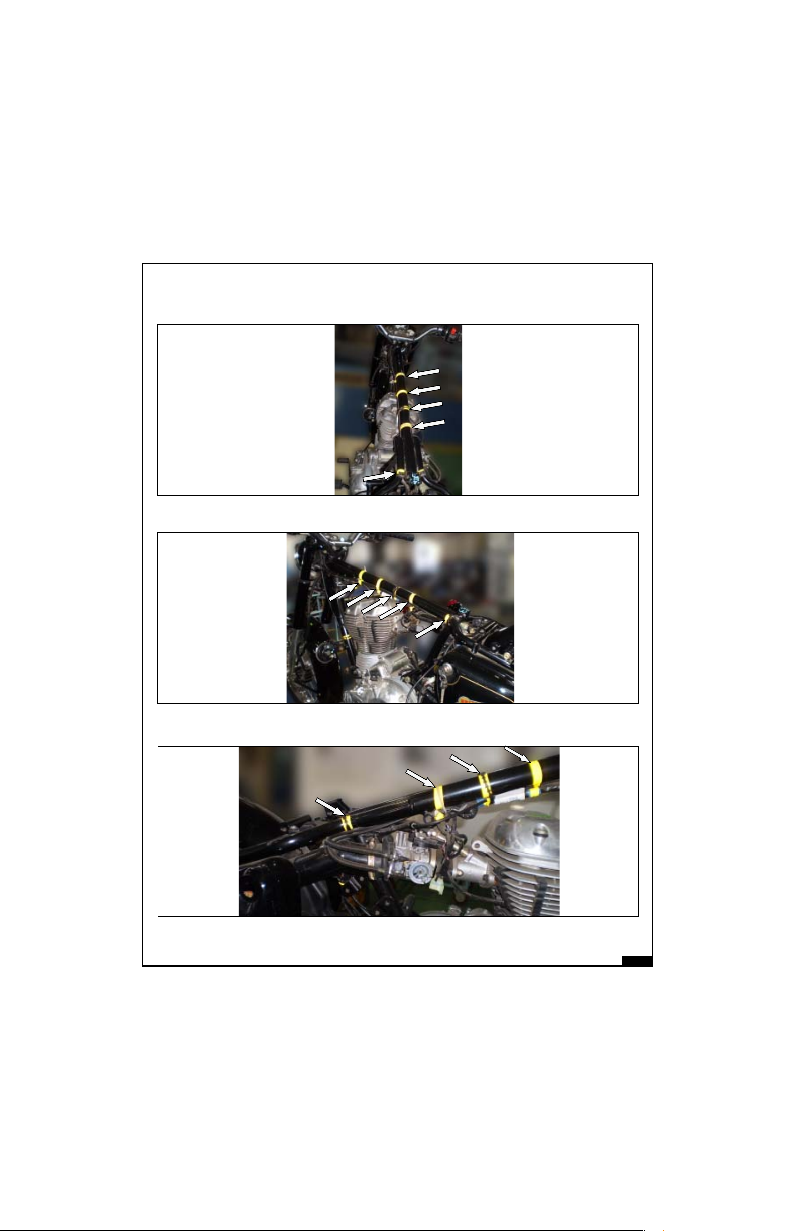
CONTROL CABLES AND WIRING HARNESS ROUTINGCONTROL CABLES AND WIRING HARNESS ROUTING
CONTROL CABLES AND WIRING HARNESS ROUTING
CONTROL CABLES AND WIRING HARNESS ROUTINGCONTROL CABLES AND WIRING HARNESS ROUTING
ALL CONTROL CABLES & WIRING HARNESS ROUTING
UNDER TANK AND SEAT TOP VIEW
UNDER TANK LH VIEW
UNDER TANK RH VIEW
02-15
Page 23
GENERAL GENERAL
GENERAL
GENERAL GENERAL
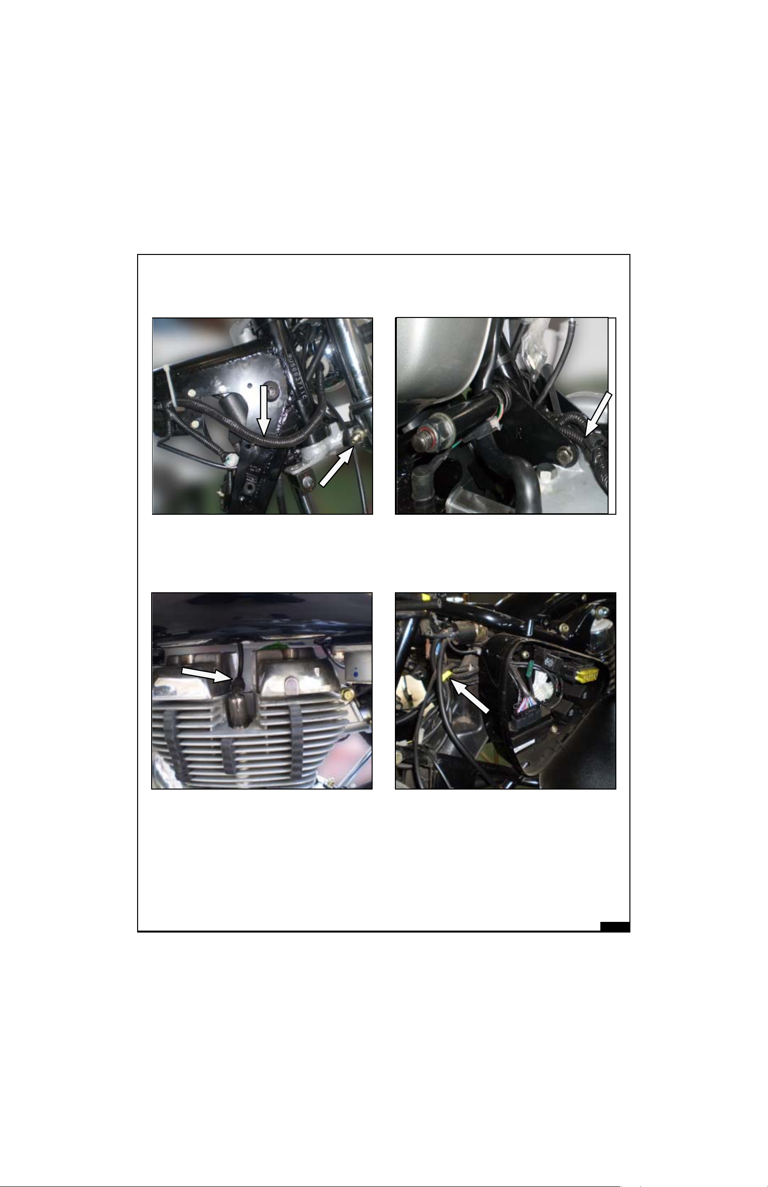
VEHICLE INFORMAVEHICLE INFORMA
VEHICLE INFORMA
VEHICLE INFORMAVEHICLE INFORMA
TIONTION
TION
TIONTION
HARNESS ROUTING STEERING RH
PLUG WIRE ROUTING
MAGNETO WIRES ROUTING
STARTER RELAY CABLE
ROUTING
02-16
Page 24
GENERAL GENERAL
GENERAL
GENERAL GENERAL
VEHICLE INFORMAVEHICLE INFORMA
VEHICLE INFORMA
VEHICLE INFORMAVEHICLE INFORMA
TIONTION
TION
TIONTION
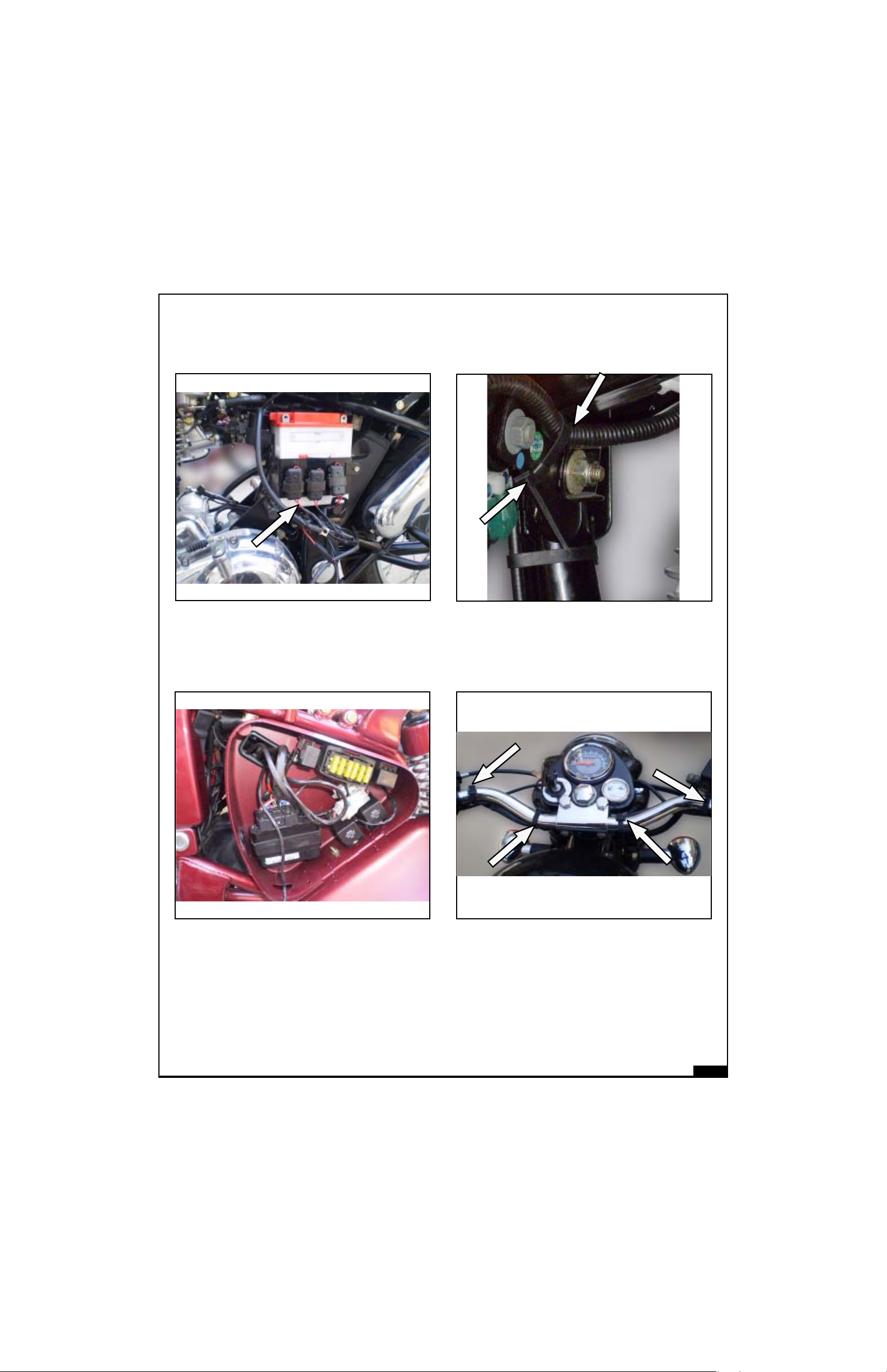
FUSE CARRIERS
ARRANGEMENT (E5 & G5)
FUSE CARRIERS
ARRANGEMENT (C5)
HORN WIRE ROUTING
HANDLE BAR WIRES ROUTING
02-17
Page 25
GENERAL GENERAL
GENERAL
GENERAL GENERAL
VEHICLE INFORMAVEHICLE INFORMA
VEHICLE INFORMA
VEHICLE INFORMAVEHICLE INFORMA
TIONTION
TION
TIONTION
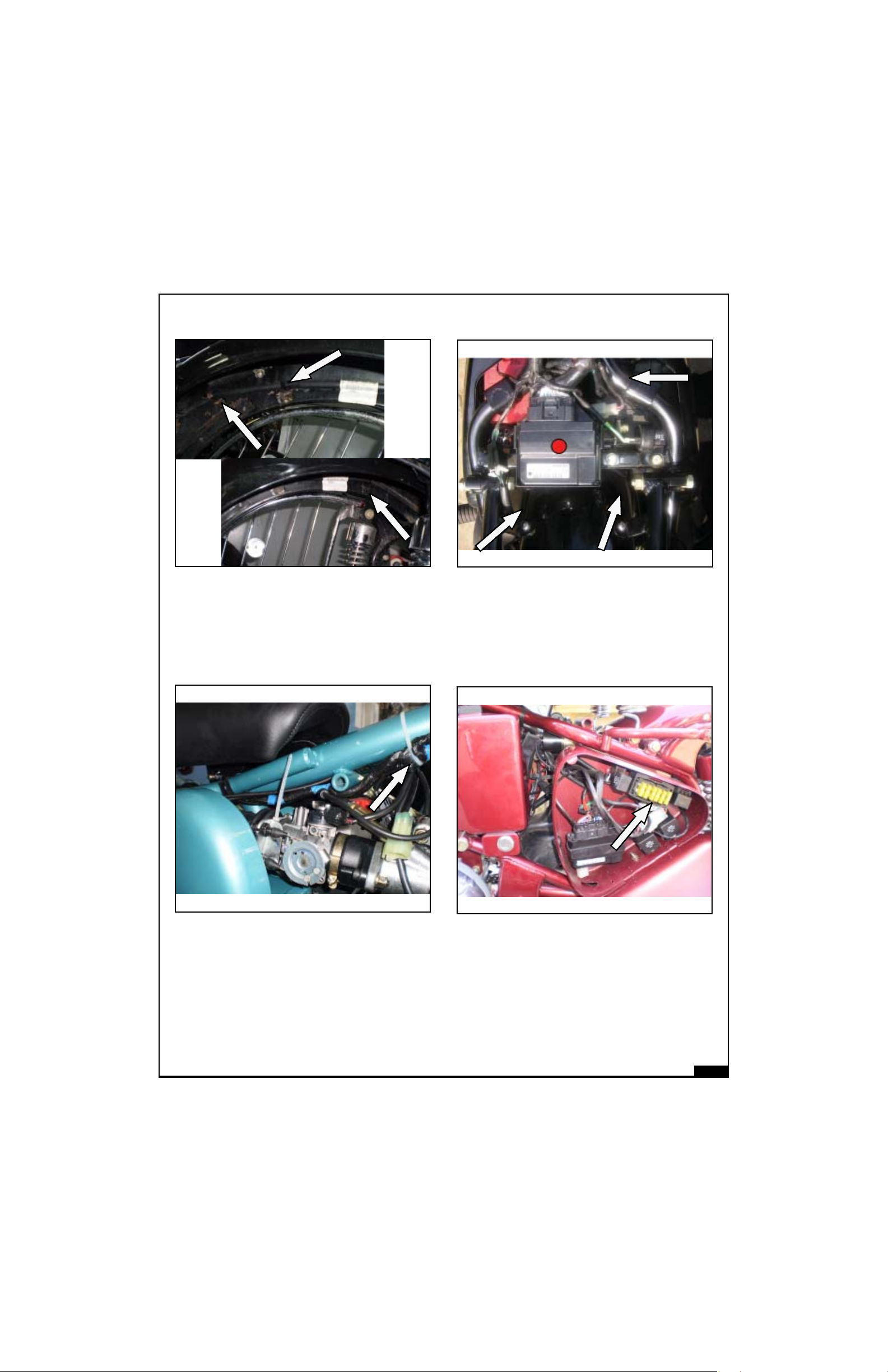
TAIL LAMP & TRAFFICATOR
WIRES ROUTING
ECU MOUNTING BULLET
ELECTRA EFI (E5 & G5)
THROTTLE BODY MOUNTING
WITH CABLES
ECU MOUNTING BULLET
CLASSIC EFI (C5)
02-18
Page 26

SECTIONSECTION
SECTION
SECTIONSECTION
THREE 03THREE 03
THREE 03
THREE 03THREE 03
SERVICE DSERVICE D
SERVICE D
SERVICE DSERVICE D
AA
A
AA
TT
T
TT
AA
A
AA
Page 27
SERSER
SER
SERSER
VICE LIMITS OF COMPONENTS VICE LIMITS OF COMPONENTS
VICE LIMITS OF COMPONENTS (All units in mm unless specified)
VICE LIMITS OF COMPONENTS VICE LIMITS OF COMPONENTS
WEAR LIMITS
Wear limits are given as new min, new max and service limits.
New components must be within the limits specified. Components within service limits may be reused
after careful inspection. Use of parts beyond service limit can reduce the operating life of the component
and may affect the motorcycle performance seriously.
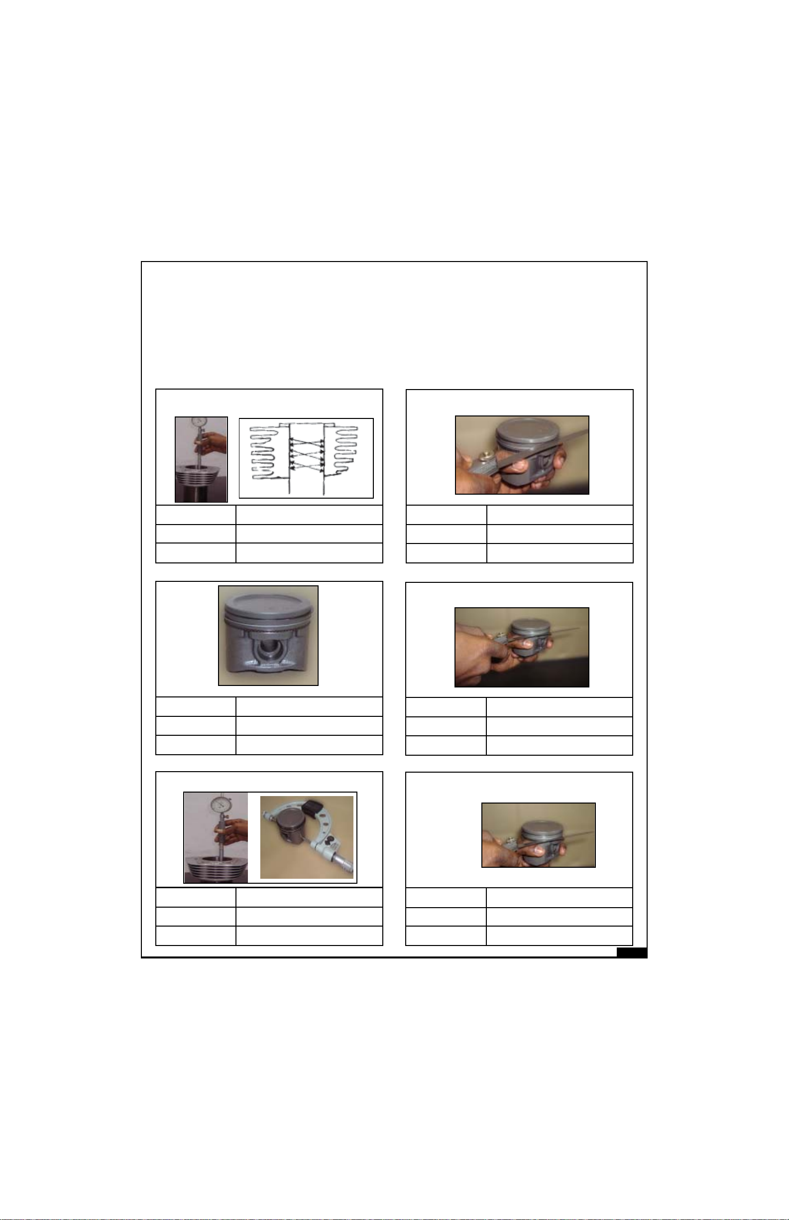
Cylinder bore
New Min.
New Max.
Service Limit
Cylinder bore :
Point of measurement
A
B
C
84.045
84.075
84.190
Piston
Ring to groove clearance : Comp. Top rings
New Min.
New Max.
Service Limit
Ring to groove clearance comp rings - Middle
0.03
0.07
0.11
New Min.
New Max.
Service Limit
New Min.
New Max.
Service Limit
83.940
83.970
83.890
Piston to bore clearance
0.095
0.115
0.30
New Min.
New Max.
Service Limit
Ring to groove clearance : oil ring
New Min.
New Max.
Service Limit
0.03
0.07
0.15
0.06
0.15
0.21
03-1
Page 28
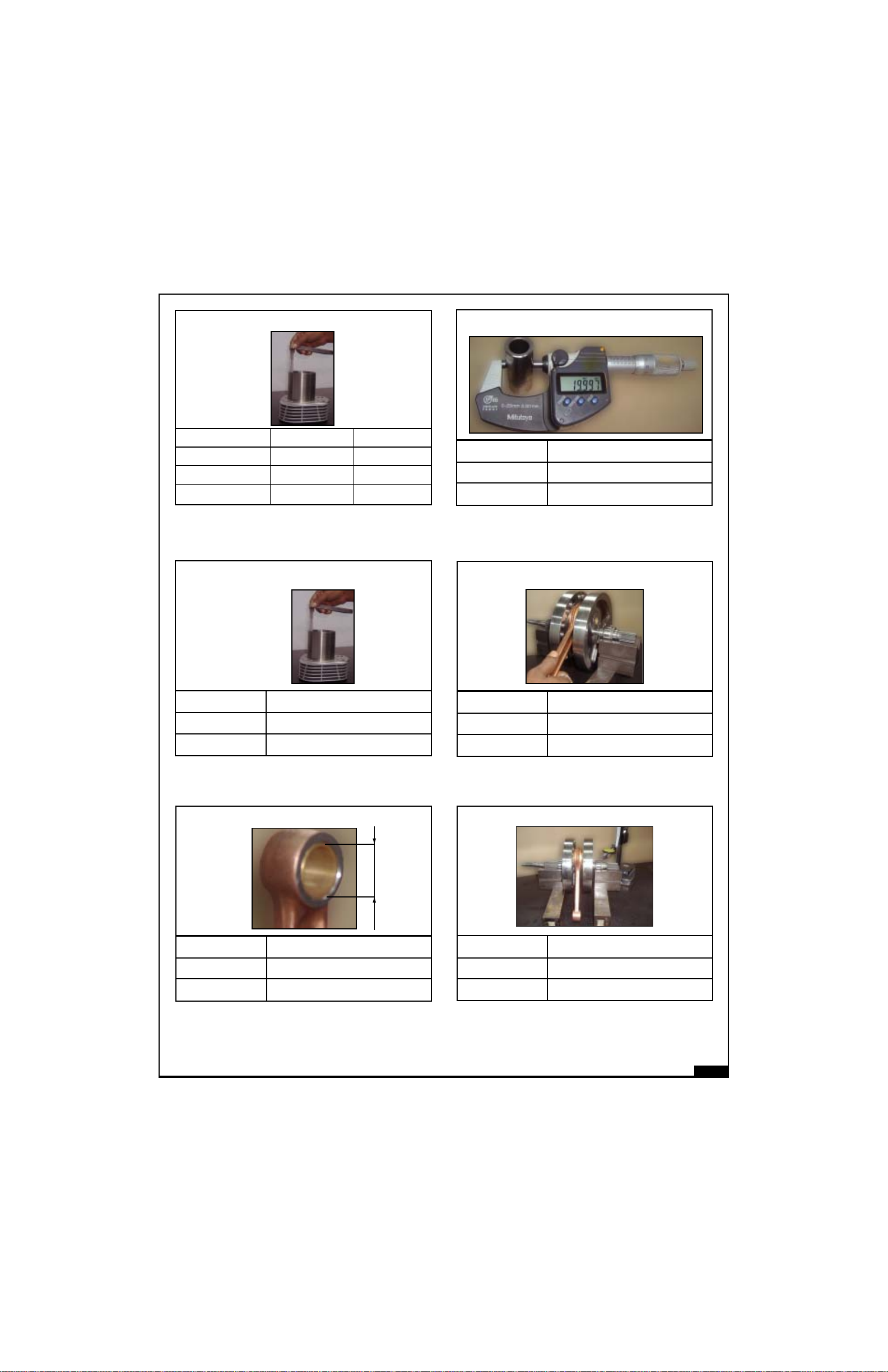
Piston ring end gap : compression
From top 1st 2nd
New Min. 0.20 0.35
New Max. 0.35 0.50
Service Limit 0.70 0.85
New Min.
New Max.
Service Limit
Piston Pin diameter
19.992
19.997
19.982
New Min.
New Max.
Service Limit
Piston ring end gap - Oil Ring
0.20
0.70
0.90
Small end bore inner diameter
New Min.
New Max.
Service Limit
Big end axial play
0.20
0.55
0.65
Crank shaft : Run out
New Min.
New Max.
Service Limit
20.007
20.016
20.046
New Min.
New Max.
Service Limit
0.00
0.04
0.08
03-2
Page 29
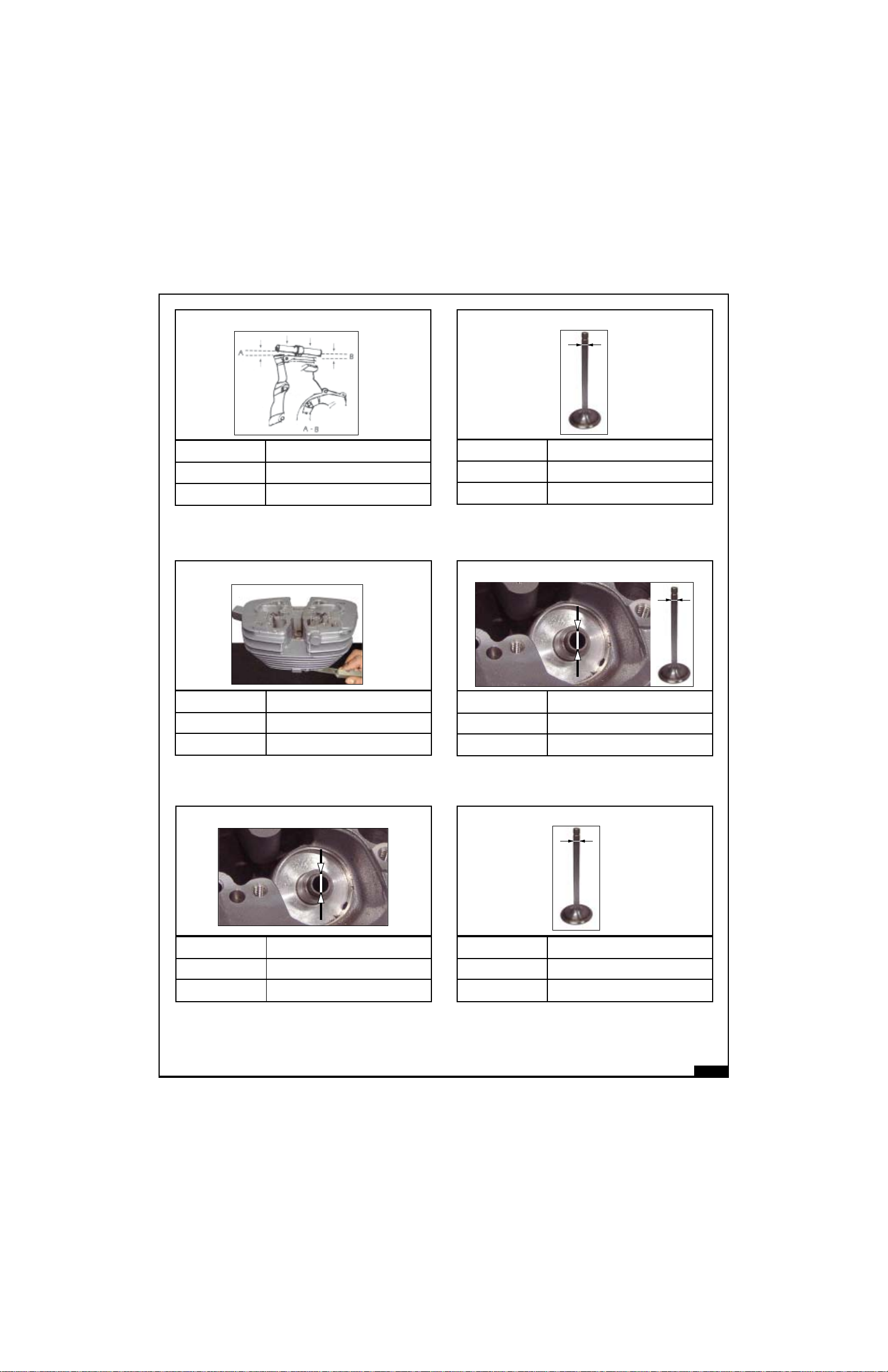
Connecting rod bend
Valve stem OD (Inlet)
New Min.
New Max.
Service Limit
New Min.
New Max.
Service Limit
0.00
0.05
0.08
Cylinder Head warpage
0.00
0.05
0.07
New Min.
New Max.
Service Limit
New Min.
New Max.
Service Limit
6.965
6.980
6.955
Valve to guide (inlet) clearance
0.02
0.05
0.08
New Min.
New Max.
Service Limit
Valve guide bore
7.00
7.015
7.25
New Min.
New Max.
Service Limit
Valve stem OD (Exhaust)
6.945
6.960
6.935
03-3
Page 30
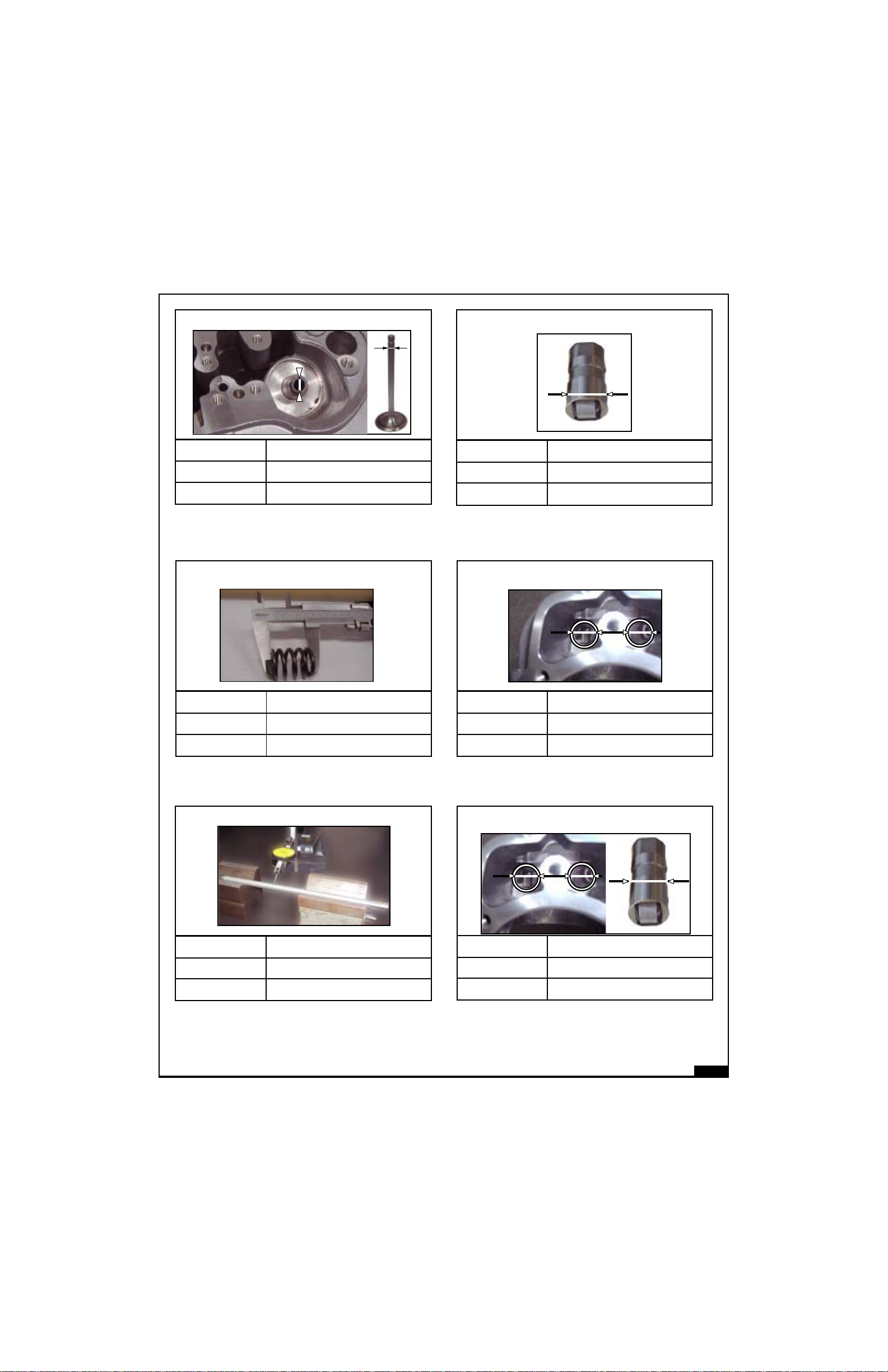
Valve to guide (Exhaust) Clearance
Hydraulic Tappet OD
New Min.
New Max.
Service Limit
New Min.
New Max.
Service Limit
0.04
0.07
1.00
Valve Spring : length
42.80
44.80
41.50
New Min.
New Max.
Service Limit
New Min.
New Max.
Service Limit
21.387
21.405
21.380
Hydraulic Tappet guide bore
21.417
21.438
21.450
New Min.
New Max.
Service Limit
Push rod run out
0.00
0.02
0.05
Hydraulic tappet to guide clearance
New Min.
New Max.
Service Limit
0.012
0.051
0.060
03-4
Page 31

Main shaft Outer diameter
Selector fork shaft outer diameter
A
B
Location A B
New Min. 19.99 23.93
New Max. 20.00 23.95
Service Limit 19.97 23.90
Lay shaft Outer diameter
X
Y
Location X Y
New Min. 17.99 23.95
New Max. 18.00 23.97
Service Limit 17.97 23.93
New Min.
New Max.
Service Limit
New Min.
New Max.
Service Limit
9.96
9.98
9.94
Selector fork inner diameter
10.00
10.03
9.98
New Min.
New Max.
Service Limit
Cam plate inner diameter
13.01
13.03
13.00
New Min.
New Max.
Service Limit
Selector fork lug thikness
3.90
3.95
3.88
03-5
Page 32

Lay shaft 1st gear inner diameter
Pivot cam plate outside diameter
New Min.
New Max.
Service Limit
Lay shaft 2nd gear inner diameter
New Min.
New Max.
Service Limit
18.03
18.06
18.09
24.00
24.03
24.06
New Min.
New Max.
Service Limit
New Min.
New Max.
Service Limit
12.98
13.00
12.96
Clutch spring Length
64.5
65.5
60.0
Main shaft 3rd & 4th gear inner diameter
MS 4
New Min.
New Max.
Service Limit
24.00
24.03
24.06
MS 3
Friction plate with insert : thickness
New Min.
New Max.
Service Limit
2.95
3.05
2.60
03-6
Page 33

Clutch steel plate : Distortion
Throttle cable free play
New Min.
New Max.
Service Limit
Duplex Chain - Length across 21 pins
New Min.
New Max.
Service Limit
0.00
0.05
0.10
190.00
191.00
195.00
New Min.
New Max.
Service Limit
New Min.
New Max.
Service Limit
-
1 mm
2 mm
Drive chain : slackness
20.00
30.00
-
New Min.
New Max.
Service Limit
Clutch cable -Free play
2 mm
4 mm
-
New Min.
New Max.
Service Limit
Rear Sprocket chain pull off
-
-
5.00
03-7
Page 34

Sprocket
Brake drum rear : Internal dia.
GOOD
New Min.
New Max.
Service Limit
Drive chain length across 21 pins
REPLACE
Sharp, bend broken teeth
New Min.
New Max.
Service Limit
152.40
152.50
153.50
Wheel rim: Face out / Run out
New Min.
New Max.
Service Limit
New Min.
New Max.
Service Limit
320
322
328
Brake lining thickness
3.80
4.06
2.00
New Min.
New Max.
Service Limit
New Min.
New Max.
Service Limit
0
1.0 mm
2.00 mm
Axle shaft : run out
0.00
0.01
0.02
03-8
Page 35

Main tube - run out
Caliper Piston Outer Diameter
OD
New Min.
New Max.
Service Limit
Front fork assembly spring : length
New Min.
New Max.
Service Limit
0.00
-
0.04
538
544
527
New Min.
New Max.
Service Limit
New Min.
New Max.
Service Limit
-
-
25.31mm
Master Cylinder piston OD
-
-
12.64 mm
New Min.
New Max.
Service Limit
Caliper Bore Inner Diameter
ID
-
-
25.46 mm
New Min.
New Max.
Service Limit
Master Cylinder Bore
-
-
12.76 mm
03-9
Page 36

Tyre tread : Depth
New Min.
New Max.
Service Limit
New Min.
New Max.
Service Limit
-
-
1.00 mm
Spark Plug Gap
0.7
0.8
-
03-10
Page 37

PERIODICAL MAINTENANCEPERIODICAL MAINTENANCE
PERIODICAL MAINTENANCE
PERIODICAL MAINTENANCEPERIODICAL MAINTENANCE
The schedule provided herein is based upon average riding conditions and indicates the mileage at which regular
inspections, adjustments, replacements and lubrications must be carried out. The frequency of the maintenance
must be shortened depending upon the severity of the driving condition OR if the motorcycle is used in a very dusty
environment, severe climatic cold and hot conditions, bad roads, stagnant water etc.,
S.
No.
DESCRIPTION
SCHEDULE
Kms (x 1000) 0.5 3 6 9 12 15 18 21 24 27 30
Miles (x 1000) 0.3 2 3.75 6 7.5 9.5 11.25 13 15 17 18.75
1 Engine Oil R R R R R R
2 Engine oil filter R R R R R R
3 Engine sump oil strainer C C C C C C
4
Magnetic drain plug under gear box on crankcase RH
CCCCCC
5 Spark plug A A A A A R AAAA R
6 HT lead I I I I I I I I I I I
7 Fuel hose I I I I R I I I R I I
8 Fuel Pump Check for screw tightness in all services
9 Accelerator cable play A A A A A A AAAA A
10 Rubber hose, Air filter to Throttle body I I I I R I I I R I I
11 Rubber hose, Inlet manifold I I I I R I I I R I I
12 Air filter element C C C C R C C C R C C
13 Inlet / Exhaust valve seating I I
14 Cylinder head D
15 Exhaust system D
16 Rear brake pedal pivot L L L L L L LLLL L
17 Battery terminals (apply petroleum jelly) C C C C C C C C C C C
18 Battery Electrolyte level I I I I I I I I I I I
19 Earth wire eyelet (behind battery carrier) I I
20 Fork oil R R
21 Rear brake cams L L L L L
22 Steering ball races L L
23 Spokes tightness I I I I I I
24 Wheel rim run out I I I I I
25 Tyre wear I I I I I I I I I I
A : Adjust C : Clean D : De-carboniseI : Inspect L : Lubricate R : Replace
NOTE :
For maintenance after 30,000 Kms, (18,750 miles) please repeat the same frequency levels specified above.
03-11
Page 38

PERIODICAL MAINTENANCPERIODICAL MAINTENANC
PERIODICAL MAINTENANC
PERIODICAL MAINTENANCPERIODICAL MAINTENANC
EE
E
EE
AIR FILTER CLEANING
BULLET ELECTRA EFI (E5/G5)
Remove the 2 air filter lid mounting screws
and take out air filter lid
Remove the 3 cover mounting screws &
take out cover
BULLET ELECTRA CLASSIC EFI (CS)
Blow compressed air from outside to
inside.
Check for cracks, holes, clogging etc.
Replace, if defective
Assemble in the reverse order of
dismantling.
SPARK PLUG CLEANING
Disconnect suppressor cap and remove
spark plug using spark plug spanner.
Clean insulator tip and electrodes using a
pointed scrapper or plug cleaner.
Open filter box cover RH
Remove centre mounting nut
Take out the air filter element
Tap off the dirt
Check and set electrode gap to 0.7 to 0.8
mm.
Refit the spark plug and connect the H.T.
lead
NOTE :
A serviceable spark plug produces thick
light blue spark across the electrode. If
spark plug produces yellow / red, side
sparks, replace it with new.
03-12
Page 39

PERIODICAL MAINTENANCPERIODICAL MAINTENANC
PERIODICAL MAINTENANC
PERIODICAL MAINTENANCPERIODICAL MAINTENANC
EE
E
EE
ENGINE OIL
OIL LEVEL CHECK
Place the motorcycle on the centre stand
Before checking the oil level start and warm
the engine for few minutes. Switch “OFF”
the ignition, wait for two minutes and then
check oil level at the inspection window on
the RH Crankcase cover
DRAINING PROCEDURE :
Keep a clean tray under the engine
Remove the two Hex Flange Bolts M5 X 16,
Sump drain Cap, “O” ring and Suction filter
Assy.
Remove the Magnetic Plug assy along with
its washer.
TILT VEHICLE RH & LH
Two level marks are provided on the
Oil level window in Cover RH Max. & Min.
If oil level is below the Min mark top up, till
the level in between Max and Min mark. Do
not overfill.
NOTE :
Oil capacity Min to Max mark is approx
350 ml.
Max
Min
OIL CHANGE :
Refer Periodical Maintenance chart
(page No. 03-10) for frequency.
Keep vehicle on level ground.
Start the engine and warm up sufficiently
so that the oil drains faster.
After the oil drains out, remove vehicle from
centre stand and tilt the vehicle to both LH
and RH sides 3 to 4 times to drain out
maximum oil.
Quantity of oil that can be drained in 2.35
Litres approximately.
Tighten the oil drain bolt with washer.
Assemble the cleaned suction filter element
in to Crank case and fix drain cap with
“O”ring.
Fill up with 15W50 API SL grade.
Refil oil quantity 2.40 Litres approximately.
03-13
Page 40

REMOVAL OF OIL FILTER ELEMENT:
The oil filter element is located on the
Crankcase Cover RH
Remove the oil filter cap mounting screws.
Remove the oil filter cap along with gasket
(Bullet Electra EFI (E5/G5) “O” ring (Bullet
Classic EFI (C5)
Remove the washer, spring, spring cap,
“O” ring and filter element.
NOTE :
Replace oil filter element whenever engine
oil is changed.
RE ASSEMBLY
Soak the new oil filter in oil for 15 minutes.
Refil the oil filter and other parts in the reverse
order of disassembly.
Start Engine, warm up for a few minutes,
switch off engine and check the oil level.
Oil level should be just below ‘Max’ level.
REAR BRAKE SWITCH ADJUSTMENT
NOTE :
Always re-check brake lamp after
adjustment of brake pedal level and
free play.
REAR WHEEL CHAIN
SLACKNESS ADJUSTMENT :
Check slackness, It should be in between
25 to 30 mm
Ensure to hold the eccentric sleeve by
spanner while tightening the lock nut which
prevent the rotation of the sleeve during
tightening the lock nut.
The backlash is first adjusted between
pinion to exhaust gear and then exhaust to
inlet gear to get effective backlash
adjustment.
Check brake light switch operation.
Loosen bottom nut and tighten top nut till the
brake light comes on when brake pedal is
pressed.
Tighten the bottom nut duly ensuring that the
brake lamp is not glowing continously.
In case brake light is continously glowing
then readjust till correct position in achieved.
03-14
Page 41

The tightening torque for M10 lock nut is
2 KG-M. This must be ensured.
Over size Cam Spindle (For Spares)
570040 : 0.1 mm Over size Spindle
570041 : 0.2 mm Over Size Spindle
CAUTION :
- After the first 800 kms (500 miles) the
backlash between the cam gears must be
checked. If a slight cam noise is observed,
then adjustment of the eccentric sleeve
has to be carried out as mentioned above.
- After adjustment to the required backlash,
both the Inlet & Exhaust lock nut in the
spindle must be tightened to the specified
torque.
If more or less adjust as follows -
Initially clean then lubricate chain > EP90
oil and rotate rear wheel.
Remove split pin and Hex castle nut on the
RH side.
Loosen anchor nut.
Loosen the brake rod nut
Loosen Hex lock nut.
Turn the adjuster cams on both sides till
25 to 30 mm chain slackness is achieved
Check and ensure that the number of
notches from the punch mark on the cam
to the notch resting on the pin are equal on
both sides.
03-15
Page 42

Rotate the wheel and apply brake and
tighten all the nuts and lock the split pin.
BRAKE CAM GREASING
(EVERY 6,000 KMS)
Remove the brake cover plate.
Clean the brake cam and apply grease.
Refit the cover plate.
REAR SHOCK ABSORBERS
ADJUSTMENT
The rear shock absorber spring preload can
be increased or reduced according to road
and load conditions.
Increase the spring preload for high load
operation.
BRAKE PEDAL PLAY ADJUSTMENT
PEDAL FREE PLAY 20 TO 30 MM
Turn in/out the adjuster nut for correct pedal
play
Reduce the spring preload for low load
operation.
The adjuster provided on the bottom of the
spring has five notches.
To carry out the adjustment proceed as
follows :
-Using special tool, place it on the slot
provided on the adjuster.
-Turn the adjuster such that the adjuster
moves up to increase the spring preload
and vice versa to reduce the spring preload.
03-16
Page 43

CAUTION
-Adjust both left and right shock absorbers
to the same notch.
FRONT FORK
A. OIL LEVEL CHECK
(EVERY 6000 KMS)
Take out front fork from the vehicle.
Remove bolt cap.
Fill 265 ml of API SG 10W-30 oil in each
leg .
Bump the fork several times and then
assemble bolt cap with “O” ring (to release
air lock if any).
Assemble back all removed parts.
DISC BRAKE FLUID LEVEL CHECK
Check brake fluid is above the ‘Min’ level in
master cylinder.
MAX
MIN
Check oil level with a 5 mm dia rod.
The level height must be 370 to 380 mm.
Top up, with API SG 10 W-30 oil, if required
B. OIL CHANGE
(EVERY 12,000 KMS)
Remove the fork ends from the vehicle.
Check as detailed in the Section 8
Top up if level is below ‘Min’ mark.
To Top up the fluid, remove the master
cylinder top cover 2 screws and take out
cover, plate & diaphragm.
Top up brake Fluid DOT 3 or DOT 4 upto
“MAX” level.
CAUTION :
As the brake fluid is highly corrosive, take
care that it does not spill over other parts.
It is suggested to wipe brake fluid
immediately, if there is any spill over in other
parts,using a soft cloth (preferably a wet
cloth).
(For further details Ref. page No. 07-12)
STEERING PLAY ADJUSTMENT
(EVERY 6,000 KMS)
Keep a wooden plank under the stand.
Rock the front end and feel the play at stem
top end as shown in fig.
03-17
Page 44

If felt, adjust as follows :
Loosen crown plate bolts as shown
picture ‘A’
B
A
Tighten stem lock nut as shown picture ‘B’
Check play.
Steering to be free with out any play.
Tighten all the screws in reverse order.
Pack grease in the top ball race.
Assemble the steering stem.
WHEEL ALIGNMENT CHECK
Hold the vehicle upright off the stand on
level ground.
Stretch a string about 100 mm above the
ground along the wheels.
If the string touches two points on the rear
wheel and two points on the front wheel (Four
point contact) then the wheels are aligned.
If string touches only three points on the
two wheels, the alignment is incorrect
STEERING BALL RACE LUBRICATION
(EVERY 12,000 KMS)
Remove steering stem assembly.
Clean and check the balls and races
thoroughly for damages / pittings /
discolouration.
Change them if found defective.
Pack grease and balls on the bottom ball
race as shown in Fig.
Adjust the rear wheel, chain adjuster till the
string touches four points.
CLUTCH CABLE FREE PLAY : (2-3mm)
LEVER END
Check clutch cable button seating position
inside lever and condition of the cable.
03-18
Page 45

Screw in or out the cable adjuster for
setting the required play at lever end (2 to
3 mm).
(B ) ADJUSTMENT AT THROTTLE BODY END
Loosen the lock nuts on both the cables.
Adjust both cables unitform and tighten the
lock nuts.
After adjustment refix cable boot.
PRIMARY CHAIN TENSION ADJUSTMENT
This vehicle is fitted with Auto chain
tensioner. Hence there is no need for
periodic manual adjustment.
THROTTLE CABLE PLAY
ADJUSTMENT
Throttle rotor free play 2-3 mm.
There are two adjuster provided - one at the top
near the throttle grip and the other on the throttle
body. Minor adjustments can be carried out at
the top.
(A ) ADJUSTMENT AT HANDLE BAR END
Slide the rubber boot, use 10 mm spanner
to adjust cable outer and lock the nut. Move
the rubber boot over the lock nuts.
THROTTLE CABLE ASSY REPLACEMENT
While replacing throttle cable following
procedure is recommended
- (A) Connect throttle cable to Rotor /
throttle grip assembly
- (B) Connect cable to throttle body and
ensure the recommended free play.
- (C) Route and strap the cable properly.
BATTERY ELECTROLYTE LEVEL :
Electrolyte level can be seen through the
casing
Level to be between max and min marks
NOTE :
Incase of maintenanace free
battery following procedure not applicable.
03-19
Page 46

If required, top up with distilled water
SPECIFIC GRAVITY CHECKING :
Check specific gravity (SG) with a
hydrometer
VALVE TIMING CUM ECCENTRIC CAM
SPINDLE
Bring piston to TDC so that the key way in the
Rotor assembly is at 12o Clock position
Check position of the exhaust cam teeth
between two punch marks with punch mark on
the Fly wheel RH shaft timing gear.
Similarly check position of the inlet cam single
punch mark align with the single punch mark on
the exhaust cam.
Specific Gravity - Min 1.22 & Max 1.24
If less, recharge the battery.
TERMINAL CLEANING :
Clean terminal with warm water and
apply petroleum jelly.
In case of sulphation clean by zero base
emary paper.
ECCENTRIC CAM SPINDLE ADJUSTMENT
The center distance adjustment of gears
is achieved by rotating the eccentric sleeve
and locking it on the spindle by using M 10
lock nut once the desired backlash is
arrived.
DECARBONISING
(EVERY 30,000 KMS)
CYLINDER HEAD
( For further details please Ref. page No.09-3)
Remove carbon from the valves, ports and
combustion chamber by scrapping. Take
care not to cause any damage to the valve
faces or valve seat inserts. Scrape gently
to avoid scoring the cylinder head.
03-20
Page 47

Remove the piston rings carefully. For
cleaning the groove in the piston, a piece
of broken piston ring thrust into a wooden
handle and filed to a chisel point can be
used.
Standard : 0.9 - 1.1 mm
Service Limit : 1.5 mm
Valve seat width is not within specification,
reface the valve seat.
CYLINDER HEAD AND VALVES
VALVE SEAT INSPECTION
Clean both Inlet & Exhaust valves and
thoroughly remove the carbon deposits
Apply light coating of Prussian blue to the
valve seats.
NOTE :
Ensure proper valve seat contact by
taping the valve in the valve seat
without rotating.
CAUTION :
If a valve face is burnt or badly worn or if it
contacts the seat unevenly, replace the valve.
Inspect the valve seat face for :
Damage face :
Replace the valve and reface the valve
seat.
Uneven seat width :
Bent or collapsed valve stem.
Replace the valve and reface the valve
seat.
Remove the valve and inspect the width of
each seat.
The seat contact should be within the
specified width and even all around the
circumference
Contact area is too high or too low. Reface
the valve seat.
03-21
Page 48

VALVE SEAT REFACING
Valve Seat cutters, a grinder or equivalent
valve seat refacing equipment are
recommended to correct worn valve seat.
If the contact area is too high on the valve,
the seat must be lowered using a 32 degree
flat cutter.
Use a 45 degree cutter to remove the
roughness or irregularities from the seat.
Using 32 degree cutter, remove top 1/4 of
the existing valve seat material.
Using 60 degree cutter, remove the bottom
1/4 of the old seat.
If the contact area is too low on the valve,
the seat must be raised using a 60 degree
inner cutter.
NOTE :
Reface the valve seat with a 45 degree cutter
when a valve guide is replaced.
Remove the cutter and inspect the area.
Install a 45 degree finish cutter and cut the
seat to proper width.
Make sure that all printing and irregularities
are removed. Refinish if necessary.
Standard seat width : 0.9 - 1.1 mm
03-22
Page 49

After cutting the seat, apply lapping
compound to the valve face and lap the
valve using light pressure.
NOTE :
Excessive lapping pressure may deform
or damage the seat.
Change the angle of lapping tool frequently
to prevent uneven seat wear.
Lapping compound can cause damage if
it enters between the valve stem and
guide.
After lapping, wash any residual compound
off the cylinder head and valve.
Recheck the seat contact after lapping.
Clean the cylinder head assembly with
solvent and blow through all oil passages
with compressed air.
Install the valve spring seats and new valve
stem seals.
Lubricate each valve stem with clean
engine oil.
Insert the intake and exhaust valve into the
valve guides.
The Parts detail of Cylinder Head assembly
NOTE :
To avoid damage to the seating face, turn
the valve slowly while inserting.
(For further details Ref. page No.05-55)
1. CYLINDER HEAD
2. SPLIT COLLAR
3. RETAINER, SPRING
4. VALVE SPRING
5. VALVE STEM SEAL
6. SEAT, SPRING
7. VALVE GUIDE
8. PLUG
9. VALVE SEAT INSERT, EXHAUST
10. VALVE EXHAUST
11. VALVE INLET
12. VALVE SEAT INSERT, INLET
03-23
Page 50

ENGINE COMPRESSION TEST
STEP-A
Start and warmup the engine to normal
running temperature.
Remove the spark plug & connect
compression gauge.
c) Switch “OFF” Ignition and engine
stop switch condition.
a) Remove spark plug & put few drops of
engine oil into the combustion chamber.
b) Connect compression gauge & repeat
the procedure as explained in the
step-A.
If compression pressure does not
increase, then check for
- blown out cylinder head gasket
- improper torque of Rocker bearing
bolts or cylinder head nuts.
- valve seat - damage / leakage
- valvestem bend
- cylinder head warpage
Hold the throttle open fully and kick several
times (5 to 6 times).
Note down the reading and repeat the
above process 3 times. Take to average
mean reading in 100 ± 10 PSI which is the
correct compression pressure. Specified
engine compression pressure.
STEP-B
In case compression pressure is less than
80 PSI, then refit spark plug & start again
to warmup the engine.
- improper valve timing
If compression pressure reading
increases, then check for
- Improper alignment of piston ring
(end gap position)
- piston ring jamed in groove.
- scoring / seizure of cylinder barrel /
piston
- worn out piston/rings
- worn out cylinder barrel
NOTE :
In case compression pressure is more
than 110 PSI then engine requires
Decarbonisation of cylinder head /
piston (combustion chamber).
03-24
Page 51

SECTIONSECTION
SECTION
SECTIONSECTION
FOUR 04FOUR 04
FOUR 04
FOUR 04FOUR 04
ENGINEENGINE
ENGINE
ENGINEENGINE
Page 52

LUBRICALUBRICA
LUBRICA
LUBRICALUBRICA
TION SYTION SY
TION SY
TION SYTION SY
STEMSTEM
STEM
STEMSTEM
04-1
Page 53

FLY
LUBRICALUBRICA
LUBRICA
LUBRICALUBRICA
TION SYTION SY
TION SY
TION SYTION SY
ROCKER
PUSH ROD
OIL PUMP
STEMSTEM
STEM
STEMSTEM
HYDRAULIC
CAM
STRAINER
CRANK
OIL SUMP
LUBRICATION SYSTEM :
Oil from the oil tank is circulated to various parts through a powerful oil pump, the capacity of which
is 4.5 litres per minute @ 2750 rpm. The oil in the sump gets filtered through an oill strainer located
in the crankcase and then pumped into the oil filter element located in the RH Cover. From here oil
is circulated to 3 main areas. The first branch goes to flywheel to lubricate crank shaft as well as
barrel piston assembly. The second branch goes to hydraulic tappet to maintain the oil pressure
constantly. The third branch goes to rocker assembly and drains down to RH cover chamber through
the push rod tunnel.
LUBRICATION OIL :
3 Specification: MOTUL 3000 4T PLUS 15W50 API, JASO MA SL - GRADE ESTER-Semi Synthetic
3 Oil capacity: 2.75 l - Initial oil filling: through Oil filler Cap = 2.5 l, through Crankcse LH Cover: 0.25 l
Oil pump : TROCHOID TYPE
Trichoidal high flow oil pump delivers oil with a pressure of 4.5 Bar. This provides
good lubrication to all the moving parts and enhances the life of the moving
parts in the engine.
04-2
Page 54

HYDRAHYDRA
HYDRA
HYDRAHYDRA
ULIC ULIC
ULIC
ULIC ULIC
TT
APPETS (ROLLER HYDRAAPPETS (ROLLER HYDRA
T
APPETS (ROLLER HYDRA
TT
APPETS (ROLLER HYDRAAPPETS (ROLLER HYDRA
LIFTER (RHVL)LIFTER (RHVL)
LIFTER (RHVL)
LIFTER (RHVL)LIFTER (RHVL)
HYDRAULIC TAPPET :
The Hydraulic tappet, (also known as RHVL Roller Hydraulic Valve Lifter) is located between
the cam and pushrod in the valve train
mechanism. It not only serves as a valve lifter
most importantly, it automatically and constantly
adjusts itself to compensate for any extra
clearance in the valve train mechanism when
the engine is running at various RPM. The
automatic adjustment is achieved with the aid
of hydraulic pressure inside the hydraulic tappet.
BENEFITS OF HYDRAULIC TAPPET :
3 Eliminates the need for manual and
periodic push rod height adjustments.
3 Compensates for clearances in the valve
train mechanism due to wear of moving
parts OR due to variations in engine
temperature.
ULIC ULIC
ULIC
ULIC ULIC
VV
V
VV
ALAL
AL
ALAL
VEVE
VE
VEVE
ROLLER HYDRAULIC VALVE LIFTER
PUSH ROD OIL
ESCAPING OIL
(D) PUSHROD
SEAT
(C)DISC VALVE
(B) OVER
HEAD OIL
FLOW PATH
OIL INLET
OIL HEAD, OIL DELIVERY CON-
TROL VALVE, LOCKING ACTION
CHECK BALL
(A) HIGH PRESSURE CHAMBER
OIL FLOW PATH
(E) LOW
PRESSURE
CHAMBER
OUTER BODY
OIL TRANSFER ANULUS
PLUNGER
CHECK BALL
SEAT
AIR ESCAPE PATH
THROUGH PLUNGER
CLEARANCE
(F) TRAPPED AIR VOLUME
(H) HIGH PRESURE
CHAMBER
ROLLER
04-3
Page 55

WORKING PRINCIPLE :
Oil enters the hydraulic tappets through a feed
hole in the body and flows into the plunger through
the plunger feed hole, filling the “low pressure
chamber” (E, in Figure)
The oil also flows around the check ball and
through the slots of the ball retainer to fill the cavity
below the plunger, called the “high pressure
chamber” (A, in Figure). Oil is forced down into
this area by momentary low pressure which
occurs once during each cam rotation.
As the hydrauilic tappet rises due to the cam
rotation, the full load of the valve train is applied
on the tappet. A predetermined and closely held
clearance of .0002/.0003 inch (.0051/.0076 mm)
between the outer diameter of the plunger and the
inner diameter of the tappet body allows a
controlled amount of oil to escape up from the high
pressure chamber.
This oil compresses the plunger spring and allows
a small relative movement of the plunger with
respect to the body.
The metering valve moves sufficiently to keep the
push rod seat hole free and unclogged. When the
engine is switched off, the valve seats on the
shoulder of the plunger to minimize drain back of
oil.
If the engine structure or valve train expands or
contracts with changes in engine temperature or
other differentials, the hydraulic tappets will
automatically adjust its own internal length to
compensate for these changes.
PRECAUTIONARY MEASURES :
The hydraulic tappets have minute holes for the
oil to circulate and to also act at the hydraulic
media, hence oil contamination must be at the
minumum. The oil and the filters in the engine,
must be changed periodically as specified.
Whenever the tappets are removed for service
OR stored in spares, they must be kept upright
(the push rod seating surface pointing upwards
and the rollers at the bottom pointing downwards)
to prevent the oil from draining off.
As cam further rotates, the tappets returns to its
original position. At this time, the plunger spring
provides the force to maintain zero back lash in
the valve train mechanism and forces the plunger
back to its original position. This allows engine oil
to once again fill the high pressure chamber so
that the cycle can be repeated during the next cam
rotation.
The overhead oil supply is accurately metered from
the “low pressure chamber”, which is at engine oil
pressure, by using a flat metal disk (metering valve
C, in Figure), which wobbles against a cylindrical
radius curved surface on the bottom of the push rod
seat (D, in Figure). Oil flows up through the hole in
the push rod seat to lubricate the overhead valve
train components (oil flow path B, in Figure).
04-4
Page 56

AUTAUT
AUT
AUTAUT
O DECOMPRESSORO DECOMPRESSOR
O DECOMPRESSOR
O DECOMPRESSORO DECOMPRESSOR
WORKING PRINCIPLE
The auto decompressor is assembled in the
exhaust cam and consists of a flyweight, spring
and pin. These are assembled in the cam
assembly with a screw
During inital cranking of the engine, the cam
rotation will be under 350 RPM. At this speed,
the flyweight will be at its resting position which
causes the pin to protrude above the base circle
of the cam lobe. This will cause the hydraulic
tappet to raise and will cause the exhaust valve
to be open thus letting out the compression form
the cylinder head.
As the engine starts, the cam rotation increases
beyond 350 RPM which inturn will cause the
flyweight to open and force the pin to rotate and
its projection will go below the cam lobe. This
will cause the tappet to return to its resting
poisition and will close the exhaust valve thus
holding the compression required to start the
engine
BENEFITS OF AUTO DECOMPRESSOR :
3 Eliminates the need to fix a manual system
which will need to be adjusted and serivced
periodically.
3 Helps in easy starting of the engine
3 Helps to reduce high initial load on the
electric start motor
04-5
Page 57

ELECTRIC STELECTRIC ST
ELECTRIC ST
ELECTRIC STELECTRIC ST
ARAR
TER SYTER SY
AR
TER SY
ARAR
TER SYTER SY
STEM & SPRASTEM & SPRA
STEM & SPRA
STEM & SPRASTEM & SPRA
G MECHANISMG MECHANISM
G MECHANISM
G MECHANISMG MECHANISM
WORKING PRINCIPLE
The sprag is located in the primary sprocket on the crankcase drive side. This provides better rigidity
of the sprag mechanism during initial crankin.
The auto decompressor mechanism further helps in reducing the load on the sprag during intitial
cranking and also prevents reversal phenomenon of the crank shaft.
04-6
Page 58

AA
A
AA
UTUT
O CHAIN O CHAIN
UT
O CHAIN
UTUT
O CHAIN O CHAIN
TENSIONER TENSIONER
TENSIONER
TENSIONER TENSIONER
ASSEMBLASSEMBL
ASSEMBL
ASSEMBLASSEMBL
YY
Y
YY
WORKING PRINCIPLE
The auto chain tensioner has a spring loaded plunger mechanism with a ratchet arrangement. It
eliminates need for manual adjustment of the primary chain tension.
It is assembled on the crankcase LH below the chain tensioner pad. The spring loaded plunger
applies force on the chain tensioner pad thereby lifting it and holding aginst the primary chain to the
required tension.
The oneway rachet mechanism in the auto chain tensioner ensures that the plunger does not drop
down due to the downward force of the chain tensioner pad.
It does not require any maintenance or service.
04-7
Page 59

ENGINE BREAENGINE BREA
ENGINE BREA
ENGINE BREAENGINE BREA
Breather
arrangement
inside the
RH cover
THER SYTHER SY
THER SY
THER SYTHER SY
STEMSTEM
STEM
STEMSTEM
WORKING PRINCIPLE
The engine breather system is located on the RH cover of the crankcase. A connecting hole directs
the engine breathing into a chamber in the RH cover which has an inbuilt deflector to deflect the oil
that may come along with the fumes from the crankcase. This oil gets drained through a small hole
provided at the bottom of the breather chamber.
The emission passes through the deflector chamber and goes to the air filter housing and passes
through the inlet manifold back into the cylinder head.
04-8
Page 60

CLCL
CL
CLCL
UTUT
UT
UTUT
CH SYCH SY
CH SY
CH SYCH SY
STEMSTEM
STEM
STEMSTEM
The clutch system has a seven plate construction to achieve increase effective diameter and improved
torque carrying capacity.
The clutch is operated through a lever on the cover LH.
04-9
Page 61

INLET MANIFOLD & INLET MANIFOLD &
INLET MANIFOLD &
INLET MANIFOLD & INLET MANIFOLD &
THRTHR
THR
THRTHR
OO
TTLE BODTTLE BOD
O
TTLE BOD
OO
TTLE BODTTLE BOD
YY
Y
YY
The inlet manifold has the fuel injector located on top portion and the throttle body attach to it.
The throttle body has a butterfly valve attached which is operated buy the throttle cables attached to
a drum on the right side.
A manual Bi starter is located on the left side and is the spring and plunger type arrangement.
An idle air bypass screw is provided on the throttle body. It is the large brass coloured screw that is
accessed from the top of the throttle body. The clamps on the throttle body may be loosened and the
throttle body rotated outwards from the top to access the screw without removing the fuel tank and
to adjust the idle speed with the bike running. Turn the screw CLOCKWISE (in) to DECREASE the
idle speed. Turn the screw ANTICLOCKWISE (out) to increase the idle speed. Remember that this
is an AIR BYPASS screw – not a throttle stop screw. Turning the screw about ¼ turn will result in an
approximate 200 RPM change in the idle speed. DO NOT adjust the throttle stop screw on the side
of the throttle body unless you are using the factory software to recalibrate the base throttle opening.
04-10
Page 62

Blow Up Charts
04-11
Page 63

43
CRANK CASE RH - COVER SIDE
45
44
10
19
1
18
10
A1
2
41
A2
34
42
35
36
33
37
32
38
39
31
30
40
24
25
23
29
26
27
22
28
20
17
12
21
16
11
15
14
10
12 13
9
11
7
A1
3
10
Key Nos.
13,14,15,16,17
4
5
6
8
7
A2
Key Nos.
30,31,32,33,34
04-12
Page 64

CRANK CASE RH - COVER SIDE
KEY No. DESCRIPTION
A1 CAM GEAR ASSEMBLY-EXHAUST WITH
DECOMPRESSOR ASSY
A2 OIL PUMP ASSEMBLY
1 TAPPET DOOR BUFFED
2 CSK SOCKET HEAD SCREW M5 X 12
3 ROTOR AND RELUCTOR ASSEMBLY
4 KEY - MAGNETO
5 PLAIN WASHER,
6 HEX. NUT M12 X 1.25
7 HEX. SOCKET HEAD CAP SCREW, M6 X 30
8 HEX. SOCKET HEAD CAP SCREW, M6 X 25
9 CAM STEADY PLATE
10 DOWEL 6 MM
11 NUT - CAM SPINDLE
12 SHIM, CAM GEAR
13 PIVOT
14 PIN ASSEMBLY
15 FLY WEIGHT
16 TORSION SPRING
17 CAM GEAR SUB ASSEMBLY- EXHAUST
18 CAM SLEEVE
KEY No. DESCRIPTION
26 FD SPROCKET 17 TEETH
27 TAB WASHER
28 NUT
29 CSK SOCKET HEAD SCREW M6 X 30
30 CIRCLIP
31 PUMP DRIVE PINION (GEAR)
32 HEX. SOCKET HEAD CAP SCREW M6 X 25
33 ‘O’ RING, OIL PUMP OUTLET
34 GASKET, OIL PUMP
35 HEX FLANGE BOLT M5 X 12
36 COPPER WASHER
37 CAP, PIVOT PIN
38 ‘O’- RING
39 ‘O’ RING
40 PIVOT, CAMPLATE
41 HEX SOCKET HEAD CAP SCREW, M6 X 60
42 STARTER MOTOR ASSEMBLY
43 HYDRAULIC VALVE LIFTER ROLLER
44 COVER STARTER MOTOR
45 HEX SOCKET, BUTTON HEAD SCREW, M5 X 12
19 CAM SPINDLE ADJUSTABLE
CAM SPINDLE ADJUSTABLE ( 0.1 OVERSIZE )
CAM SPINDLE ADJUSTABLE ( 0.2 OVERSIZE )
20 CAM, GEAR - INLET
21 HEX SOCKET PAN HEAD SCREW M5 X12
22 OIL SEAL KICK STARTER
23 COVER, KICK START SHAFT
24 OIL SEAL
25 DISTANCE PIECE
04-13
Page 65

CRANK CASE LH INSIDE VIEW
04-14
Page 66

CRANK CASE LH
KEY No. DESCRIPTION
1 CRANK CASE-LH
2 CIRCLIP
3 BALL BEARING 6305 (25 X 62 X 17)
4 BEARING SPACER
5 ROLLER BEARING NU305 (25 X 62 X 17)
6 BALL BEARING 6006
7 RETAINER PLATE, MAINSHAFT BEARING
8 HEX SOCKET HD CAP SCREW , M5 X 16
9 JACK SHAFT
10 STUD, M8 X 128
11 FLANGE NUT-M8
12 NEEDLE BEARING
13 WASHER, THRUST
14 STUD M6 X 133
04-15
Page 67

CRANK CASE RH - INSIDE VIEW
18
19
12
13
11
10
16
14
15
23
24
25
28
29
30
9
17
20
22
21
26
27
5
8
4
7
6
3
2
1
04-16
Page 68

CRANK CASE RH - INSIDE VIEW
KEY No. DESCRIPTION
1 CIRCLIP
2 DEEP GROOVE BALL BEARING – SLEEVE
GEAR
3 NEEDLE BEARING
4 SLEEVE GEAR
5 NEEDLE BEARING
6 HEX. SOCKET HEAD CAP SCREW, M6 X 12
7 BRACKET - PIN - HYDRAULIC - TAPPET
8 NEEDLE ROLLER
9 BEARING
10 DOWEL - HOLLOW
11 STUD, M8 X 128
12 FLANGE NUT-M8
13 BOLT, PAWL
14 WASHER, INSPECTION SCREW
KEY No. DESCRIPTION
18 MACHINED WASHER 6.4
19 HEX. NYLOCK NUT M6 X 1
20 HEX FLANGE BOLT M5 X 16
21 DRAIN CAP - SUMP
22 O RING- DRAIN CAP
23 SUCTION FILTER ASSY
24 STOP PLATE
25 HEX. SCREW M8 X 25,
26 OIL THROWER
27 HEX. SOCKET HEAD CAP SCREW, M5 X 35
28 LOCATING PIN (PIVOT)
29 NEEDLE BEARING
30 WASHER, THRUST
15 MAGNETIC PLUG ASSEMBLY
16 SPRING
17 PAWL, CAMPLATE
04-17
Page 69

27
ENGINE COVER - RH
49
48
7
04-18
Page 70

ENGINE COVER - RH
KEY No. DESCRIPTION
1 UCE, RH COVER SUB ASSEMPLY
2 COVER, RH
3PLUG
4 RESTRICTOR (LEE PLUG)
5 SEALING WASHER 12X15.5
6 OIL LEVEL WINDOW
7 BOLT BREATHER
8 JET,CRANKSHAFT RH
9 OIL SEAL , CRANK FEED 24X10X7
10 CIRCLIP 24N
11 WASHER, INSPECTION SCREW
12 INSPECTION SCREW, IGNITION TIMING
13 O-RING
14 OIL FILLER CAP, NYLON
15 ELEMENT - OIL FILTER
16 SPRING CAP
17 WASHER
18 SPRING
19 O-RING
20 O-RING, FILTER CAP
21 GASKET, CAP OIL FILTER
22 CAP, OIL FILTER
23 HEX FLANGE BOLT M5x16
24 GASKET, COVER PLATE
25 COVER PLATE, BREATHER CHAMBER
KEY No. DESCRIPTION
26 HEX.SCREW, M5X12
27 STATOR & PULSOR COIL ASSY -
THREE PHASE
28 PULSOR COIL FIXING SCREW
29 ALLEN SCREW M6X30
30 HEX.SOCKET HEAD CAP SCREW, M6X85
31 HEX.SOCKET HEAD CAP SCREW, M6X100
32 HEX.SOCKET HEAD CAP SCREW, M6X80
33 HEX.SOCKET HEAD CAP SCREW, M6X60
34 HEX. SOCKET HEAD CAP SCREW, M6X40
35 GASKET - COVER RH
36 OIL SEAL, KICK SHAFT
37 KICK START CRANK ASSY.
38 BOSS, KICK START CRANK
39 SPRING
40 BALL DIA 6.35
41 LEVER, KICK START CRANK
42 SLEEVE, KICK START LEVER
43 WASHER
44 CIRCLIP 10
45 HEX. BOLT M8X40
46 HEX. NUT, M8
47 SEALING WASHER 6 × 10 IS : 3175 CU
48 BREATHER PIPE
49 FLYWHEEL MAGNETO 3 PHASE
04-19
Page 71

CRANK CASE LH - COVER SIDE
04-20
Page 72

CRANK CASE LH - COVER SIDE
KEY No. DESCRIPTION
1 CRANK CASE-LH
2 DOWEL (6MM)
3 COLLAR, MAINSHAFT
4 GEAR, - JACK SHAFT
5 KEY - JACK SHAFT
6 CIRCLIP 12 × IN IS 3075 (PART I)
(FOR SHAFT)
7 DOWEL
8 NEUTRAL SWITCH WITH PACKING
9 HEX.SOCKET HD.CAP SCREW,M6 X 50
10 STUD M6 X 168
11 STUD M6 X 106
12 STUD M6 X 196
13 STUD M6 X 226
14 STUD M6 X 80
15 NUT M6X1, FLANGE NYLOC TYPE
16 SHAFT, DOUBLE GEAR
17 DOUBLE GEAR - STARTER DRIVE
18 HOUSING STARTER DRIVE
19 HEX.SOCKET HD.CAP SCREW,M5 X 45
20 HEX.SOCKET HD.CAP SCREW,M5 X 25
21 DISTANCE WASHER , SPRAG CLUTCH
KEY No. DESCRIPTION
23 BUSH, C T PAD
24 CHAIN TENSIONER PAD
25 PLAIN WASHER
26 HEX.NUT,M8
27 AUTO CHAIN TENSIONER ASSEMBLY
28 O RING,CHAIN TENSIONER ASSEMBLY.
29 HEX. SOCKET HEAD CAP SCREW, M6X20
30 SPRAG CLUTCH ASSEMBLY
31 ENGINE SPROCKET
32 SPRAG CLUTCH
33 SPRAG CLUTCH GEAR
34 NEEDLE BEARING
35 WASHER
36 HEX.HEAD SCREW M12
37 CLUTCH ASSEMBLY COMPLETE
38 NYLOCK NUT
39 CLUTCH PUSH PAD
40 BALL BEARING 6001
41 PRIMARY CHAIN
42 HEX.SOCKET HEAD CAP SCREW, M6X85
43 PLAIN WASHER
22 STUD, CHAIN TENSIONER PAD
04-21
Page 73

ENGINE COVER - LH
10
8
12
17
16
15
14
18
19
20
7
9
4
11
6
3
5
2
1
13
04-22
Page 74

ENGINE COVER - LH
KEY No. DESCRIPTION
1 LH COVER SUB ASSEMBLY
2 COVER, LH
3 BUSH
4 OIL SEAL 14 X 20 X 3
5 GASKET, COVER LH
6 OIL SEAL INA G 12 X 18 X 5
7 ASSEMBLY, CLUTCH OP
8 CABLE CLEVIS, CLUTCH OPERATING LEVER
9 CLUTCH CABLE ASSEMBLY
10 PIN, CLUTCH OPERATING LEVER
11 LOCK PIN SPRING, CLUTCH OPERATING MECH.
12 SPRING, CLUTCH OP LEVER
13 HEX. SOCKET HEAD CAP SCREW, M6 X 201
14 O-RING (PLUG)
15 OIL FILLER PLUG
16 GEAR LEVER
17 SLEEVE, GEAR LEVER
18 HEX SCREW M6 X 25
19 SEALING WASHER 6 × 10 IS : 3175 CU
20 HEX NUT M6 - IS 1364 (PART 3) - 8 - ZN.PL
04-23
Page 75

GEAR TRAIN ASSEMBLY
04-24
Page 76

GEAR TRAIN ASSEMBLY
KEY No. DESCRIPTION
A1 LAY SHAFT SUB ASSEMBLY
A2 MAIN SHAFT SUB ASSEMBLY
1 MAIN SHAFT
2 MAIN SHAFT 2ND GEAR
3 WASHER, THRUST
4 MAIN SHAFT 4TH GEAR
5 CIRCLIP
6 MAIN SHAFT 3RD GEAR / 4TH GEAR
7 MAIN SHAFT 1ST GEAR7
8 LAY SHAFT
9 WASHER, THRUST
10 LAY SHAFT 2ND GEAR
11 LAY SHAFT HIGH GEAR
12 LAY SHAFT 3RD & 4TH GEAR ASSY.
KEY No. DESCRIPTION
16 BUSH
17 SELECTOR FORK LH
18 SELECTOR FORK CENTRE
19 SELECTOR FORK RH
20 SELECTOR FORK SHAFT
21 CIRCLIP 10N
22 CAM PLATE ASSEMBLY
23 RATCHET PLATE
24 RIVET, CAM PLATE/RATCHET PLATE
25 ROLLER
26 PIN
13 WASHER, THRUST
14 ASSEMBLY, LAYSHAFT 1ST GEAR
15 LAYSHAFT 1st GEAR
04-25
Page 77

GEAR SHIFTING
KICK STARTER(E5 & G5)
5
04-26
Page 78

GEAR SHIFTING
KEY No. DESCRIPTION
1 SS ROCKER SHAFT ASSEMBLY,
2 PIN PIVOT
3 STRIKER, GEAR CHANGE
4 SPRING
5 SPRING, GEAR CHANGE STRIKER
6 SPACER
7 PIVOT BEARING, ROCKER SHAFT UPPER
8 HEX. SOCKET HEAD CAP SCREW, M6 X 12
9 PIVOT BEARING, ROCKER SHAFT BOTTOM
10 ASSEMBLY, GEAR LEVER SHAFT
11 STOP PIN
12 O-RING
13 HEX. SOCKET HEAD CAP SCREW, M5 X 40
KICK STARTER(E5 & G5)
KEY No. DESCRIPTION
A1 KICKSTARTER SHAFT SUB ASSEMBLY
1 KICKSTART SHAFT
2 SPRING
3 PLUNGER
4PAWL
5 WASHER, THRUST
6 KICKSTART GEAR ASSEMBLY
7 KICKSTARTER GEAR 35T
8 BUSH
9 CIRCLIP
10 SPRING
11 HEX SCREW M6
04-27
Page 79

CYLINDER HEAD, BARREL, PISTON & CRANKSHAFT
23
15
14
25
24
27
22
18
20
11
10
9
6
3
8
2
12
26
7
5
39
19
17
21
36
38
16
4
13
30
32
38
37
34
37
38
35
37
39
38
33
29
28
31
CRANK SHAFT ASSY.
PISTON ASSY.
04-28
Page 80

CYLINDER HEAD, BARREL, PISTON & CRANKSHAFT
KEY No. DESCRIPTION
1 CYLINDER HEAD SUB ASSY
(CYLINDER HEAD, VALVE GUIDE, VALVE SEATS)
2 CYLINDER HEAD - ONLY MACHINED
HEAD
3 VALVE GUIDE
4 VALVE SEAT INSERT, EXHAUST
5 VALVE SEAT INSERT,INLET
6 DOWEL (6mm)
7 SPARK PLUG - M 10 - (UR5DC)
8 SPARK PLUG - M 14 - (W5DC)
9 SEAT, SPRING
10 VALVE STEM SEAL
11 VALVE SPRING
12 VALVE INLET
13 VALVE EXHAUST
14 RETAINER,SPRING
15 SPLIT COLLAR
16 PLUG
17 ROCKER BEARING SET-EXHAUST
18 ROCKER ARM - INLET
KEY No. DESCRIPTION
21 ROCKER ARM, EXHAUST
22 GASKET, ROCKER COVER INLET
23 ROCKER COVER - INLET
24 WASHER-SEAL
25 HEX HEAD SCREW-ROCKER COVER
26 GASKET, ROCKER COVER EXHAUST
27 ROCKER COVER - EXHAUST
28 CYL. BARREL ASSY
29 DOWEL PIN
30 DOWEL PIN
31 GASKET CYLINDER BARREL
32 GASKET HEAD(MLS)
33 PUSH ROD ASSY, EXHAUST
34 PUSH ROD ASSY, INLET
35 STUD, EXHAUST
36 DAMPER PAD - CYLINDER HEAD LH
37 DAMPER PAD - CYLINDER HEAD RH
38 DAMPER PAD TAPER- BARREL
39 DAMPER PAD STRAIGHT - BARREL
19 HEX.SOCKET HD.CAP SCREW,M6 X 55
20 ROCKER BEARING SET-INLET
04-29
Page 81

570482/b
570478/b
DAMPER PAD POSITION DETAILS
Number of damper pads per engine = 15
INLET SIDE VIEW
570479/b
570480/b
570479/b
570482/b
Part No.
570478/b
570479/b
570482/b
Description
Damper pad-cylin-
der head LH
Damper pad-
cylinder head RH
EXHA UST SIDE VIEW
570479/b
Quantity per
engine
2
4
Image
570480/b
Part No.
570480/b
570482/b
570482/b
Description
Damper pad
straight - Barrel
Damper pad
taper - Barrel
Quantity per
engine
3
6
Image
04-30
Page 82

SECTIONSECTION
SECTION
SECTIONSECTION
FIVE 05FIVE 05
FIVE 05
FIVE 05FIVE 05
TT
ORQUE SPECIFICAORQUE SPECIFICA
T
ORQUE SPECIFICA
TT
ORQUE SPECIFICAORQUE SPECIFICA
ENGINE DISMANTLINGENGINE DISMANTLING
ENGINE DISMANTLING
ENGINE DISMANTLINGENGINE DISMANTLING
TIONSTIONS
TIONS
TIONSTIONS
INSPECTION & ASSEMBLINSPECTION & ASSEMBL
INSPECTION & ASSEMBL
INSPECTION & ASSEMBLINSPECTION & ASSEMBL
YY
Y
YY
Page 83

TORTOR
TOR
TORTOR
QQ
UE SPECIFICAUE SPECIFICA
Q
UE SPECIFICA
QQ
UE SPECIFICAUE SPECIFICA
TION - ENGINETION - ENGINE
TION - ENGINE
TION - ENGINETION - ENGINE
S.
PART
No
No.
1 570013 HEX SOCKET HD CAP SCREW, M5 X 16 RETAINER PLATE / SUCTION FILTER MTG 0.60 6
2 570016 HEX.SOCKET HD.CAP SCREW, M5 X 45 E START HOUSING COVER 0.60 6
3 570094 HEX.SOCKET HD.CAP SCREW, M5 X 25 E START HOUSING COVER 0.60 6
4 570232 HEX.SOCKET HD.CAP SCREW, M6 X 12 STOP PLATE, PIVOT PIN / COVER LH /
5 570020 HEX FLANGE BOLT CRANK CASE SET ASSY 2.50 25
6 145879 FLANGED HEX. BOLT M8 X 112 FRONT ENGINE MTG PLATE 2.50 25
7 145867 FLANGED HEX. NUT M8 X 1.25 FRONT ENGINE MTG PLATE / EXHAUST PIPE MTG 2.50 25
8 570088 STUD 168L (M6) CRANKCASE SET ASSY 1.00 10
9 570090 STUD 106L (M6) CRANKCASE SET ASSY 1.00 10
10 570089 STUD 196L (M6) CRANKCASE SET ASSY 1.00 10
11 570024 HEX.SOCKET HD.CAP SCREW, M6 X 50 CRANKCASE SET ASSY 1.00 10
12 570085 DOWEL, STUD (M6) CRANKCASE SET ASSY 1.00 10
13 570025 HEX.SOCKET HD.CAP SCREW, M6 X 90 CRANKCASE SET ASSY 1.00 10
DESCRIPTION LOCATION
PIVOT BRG LOWER 1.00 10
TORQUE VALUE
Kg / M. N / M.
14 570086 STUD 226L (M6) CRANKCASE SET ASSY 1.00 10
15 570087 STUD 133L (M6) CRANKCASE SET ASSY 1.00 10
16 570091 STUD 80L (M6) CRANKCASE SET ASSY 1.00 10
17 145866 FLANGED HEX. NUT M6 X 1 CRANKCASE SET ASSY 1.00 10
18 570030 HEX.SOCKET HD.CAP SCREW, M6 X 20 AUTO CHAIN TENSIONER ASSY / COVER LH 1.00 10
19 570095 CHAIN TENSIONER STUD, (M8) AUTO CHAIN TENSIONER ASSY 2.50 25
20 141051 HEX.NUTM8 AUTO CHAIN TENSIONER ASSY / KS CRANK 2.50 2 5
21 570100 NUT (M10 X 1) CAM SPINDLE SLEEVE NUT 2.00 20
22 570421 HEX.SOCKET HD.CAP SCREW, M6 X 30 CAM STEADY PLATE 1.00 10
23 570132 HEX.SOCKET HD.CAP SCREW, M6 X 25 CAM STEADY PLATE 1.00 10
24 500355 HEX.SOCKET HD.CAP SCREW M6 X 16, BRACKET, PIN, HYD, TAPPET / INLET FLANGE 1.00 10
25 570198 CSK SOCKET HEAD SCREW M5 X 0.8 X 12 TAPPET DOOR 0.60 6
26 570051 HEX.SOCKET HD.CAP SCREW, M4 X 30 OIL PUMP HOUSING ASSY 0.60 6
27 570064 HEX.HEAD SCREW M12 X 1.25 X 20 SHAFT LH 4.80 48
28 550025 HEX NUT M12 X 1.25 SHAFT RH 4.80 48
29 570463 HEX.SOCKET HD.CAP SCREW, M6 X 60 E START MOTOR MOUNTING / COVER RH 1.00 10
05-1
Page 84

TORTOR
TOR
TORTOR
QQ
UE SPECIFICAUE SPECIFICA
Q
UE SPECIFICA
QQ
UE SPECIFICAUE SPECIFICA
TION - ENGINETION - ENGINE
TION - ENGINE
TION - ENGINETION - ENGINE
S.
PART
No
No.
30 570215 BOLT, PAWL (M6 X 1) GEAR BOX INDEX 1.00 10
31 570233 HEX.SOCKET HD.CAP SCREW, M5 X 40 PIVOT BEARING, ROCKER SHAFT LOWER 0.60 6
32 550138 CSK SOCKET HEAD SCREW M5 X 0.8 X 16, COVER, KICKSTART SHAFT 0.60 6
33 145090 HEX SCREW M6 X 16 KICKSTART, SPRING 1.00 10
34 570240 HEX.SOCKET HD.CAP SCREW, M5 X 35 COVER K.S. GEAR 0.60 6
35 142291 HEX SCREW M8 X 22.5 STOP PLATE, KICK PAWL 2.50 25
36 111914 HEX.BOLT M8 X 40 ASSY, KICK START CRANK 2.50 25
37 143498 HEX. SCREW M6 X 25 GEAR LEVER 1.00 10
38 141060 HEX. NUT M6 GEAR LEVER 1.00 1 0
39 570246 NUT (M35 X 1.5) FD SPROCKET 8.00 80
40 570440 HEX SCREW M6 X 1 X 35 CLUTCH ASSY 1.00 1 0
41 560525 HEX. NUT WITH NYLOC INSERT M16X1.5, MAIN SHAFT, CLUTCH SIDE 4.80 4 8
42 570444 BOLT, BREATHER (M12) BREATHER ASSY 2.00 20
43 570422 HEX.SOCKET HD.CAP SCREW, M6 X 100 COVER RH 1.00 10
DESCRIPTION LOCATION
TORQUE VALUE
Kg/M.
N/M.
44 570130 HEX.SOCKET HD.CAP SCREW, M6 X 85 COVER RH 1.00 10
45 570423 HEX.SOCKET HD.CAP SCREW, M6 X 40 COVER RH 1.00 10
46 570021 HEX.SOCKET HD.CAP SCREW, M6 X 80 COVER RH 1.00 10
47 570425 HEX.SOCKET HD.CAP SCREW, M5 X 12 COVER PLATE, BREATHER CHAMBER 0.60 6
48 570431 HEX FLANGE BOLT CAP, OIL FILTER 0.60 6
49 570131 HEX.SOCKET HD.CAP SCREW, M6 X 60 ROCKER BEARING 1.00 10
50 570129 HEX HEAD SCREW ROCKER COVER MTG ROCKER COVER 1.00 10
51 570175 FLANGED HEX. BOLT M8 X 90 STEADY BRACKET CYL. HEAD 2.50 25
52 570177 HEX NUT WITH NYLON INSERT, M8 STEADY BRACKET CYL. HEAD 2.50 25
53 500327 FLANGE NUT M8 CYL.HEAD MOUNTING 2.50 25
54 500104 STUD, M8 X 128 CY.HEAD MOUNTING 2.50 25
55 570304 HEX SOCKET HEAD CAP SCREW M6 X 12 PIVOT BEARING, UPPER 1.0 0 1 0
56 550095 ALLEN SCREW M6 X 30 STATOR COIL MOUNTING 1.00 10
57 570276 MAGNETIC PLUG ASSY CRANKCASE DRAIN 2.00 20
58 500339 STUD EXHAUST EXHAUST PIPE MTG 0.60 6
59 572025 SPARK PLUG 2.80 28
05-2
Page 85

ENGINE DISMANTLING ,ENGINE DISMANTLING ,
ENGINE DISMANTLING ,
ENGINE DISMANTLING ,ENGINE DISMANTLING ,
INSPECTION INSPECTION
INSPECTION
INSPECTION INSPECTION
AND AND
AND
AND AND
ASSEMBLASSEMBL
ASSEMBL
ASSEMBLASSEMBL
YY
Y
YY
COMPONENTS COMPONENTS
COMPONENTS
COMPONENTS COMPONENTS
REMOREMO
REMO
REMOREMO
MOUNTED ON THE FRAME.MOUNTED ON THE FRAME.
MOUNTED ON THE FRAME.
MOUNTED ON THE FRAME.MOUNTED ON THE FRAME.
Cylinder head assembly
Cylinder barrel & Piston
Crank case Cover RH
Crank case Cover LH
Clutch assembly
Inlet and Exhaust Cam assembly
Oil pump Assembly
ENGINE SHOULD BEENGINE SHOULD BE
ENGINE SHOULD BE
ENGINE SHOULD BEENGINE SHOULD BE
REMOREMO
REMO
REMOREMO
FOR FOR
FOR
FOR FOR
Crank case repair/replacement.
Crank shaft and main bearings
Roller Hydraulic Valve Lifter (RHVL)
Transmission parts like Gears, Mainshaft,
Kick Starter Gear, Pawl, Spring , Plunger
VED VED
VED
VED VED
VED FRVED FR
VED FR
VED FRVED FR
THE FOLLTHE FOLL
THE FOLL
THE FOLLTHE FOLL
replacement.
replacement.
Layshaft, repair / replacement
replacement. (only for Bullet Electra EFI
E5/G5)
WITH WITH
WITH
WITH WITH
THATHA
T CAN BET CAN BE
THA
T CAN BE
THATHA
T CAN BET CAN BE
THE ENGINETHE ENGINE
THE ENGINE
THE ENGINETHE ENGINE
OM OM
OM
OM OM
THE FRAMETHE FRAME
THE FRAME
THE FRAMETHE FRAME
OO
WING JOBS:WING JOBS:
O
WING JOBS:
OO
WING JOBS:WING JOBS:
Remove the front and rear flange nuts,
washer at the front & rear mounting of the
fuel tank.
NOTE :
DISMANTLING PROCEDUREDISMANTLING PROCEDURE
DISMANTLING PROCEDURE
DISMANTLING PROCEDUREDISMANTLING PROCEDURE
Disconnect fuel hose. Take care to ensure
Disconnect fuel pump module and low fuel
Before starting to dismantle engine,
crank gently & bring piston to TDC.
fuel does not spill.
sensor couplers.
Lift the tank from the seat side & remove.
CAUTION :
Keep a cloth on the front end of the fuel
tank, (below the handle bar clamp) to
avoid damage to the fuel tank while
removing.
05-3
Page 86

SEASEA
T REMOT REMO
SEA
T REMO
SEASEA
T REMOT REMO
ELECTRA EFI (E5/G5)ELECTRA EFI (E5/G5)
ELECTRA EFI (E5/G5)
ELECTRA EFI (E5/G5)ELECTRA EFI (E5/G5)
Remove 4 nos. flange bolts from both sides
of the seats.
Remove the pillion holder, lift from the rear
end and pull out the seat
BB
ULLET CLASSIC EFI (C5)ULLET CLASSIC EFI (C5)
B
ULLET CLASSIC EFI (C5)
BB
ULLET CLASSIC EFI (C5)ULLET CLASSIC EFI (C5)
VV
AL BAL B
V
AL B
VV
AL BAL B
ULLETULLET
ULLET
ULLETULLET
Remove the 2 screws, at the bottom of the
LH switch module and separate the
module from the handle bar.
Disconnect the cable from the lever.
Remove the mounting bolts as shown and
remove the seat.
Manual Bi starter
Remove cable from the straps in the
frame.
05-4
Page 87

CLCL
UTUT
CL
CLCL
Slacken the adjuster at the clutch cover end
Take out clutch cable from the cover.
Remove the clutch cable from the clutch
CH CABLE REMOCH CABLE REMO
UT
CH CABLE REMO
UTUT
CH CABLE REMOCH CABLE REMO
and disconnect the cable from the lever.
lever at handle bar end.
VV
V
VV
ALAL
AL
ALAL
REMOREMO
REMO
REMOREMO
BODBOD
BOD
BODBOD
Loosen the throttle body flange & bellow
Remove the throttle body by pushing
VV
AL OF AL OF
V
AL OF
VV
AL OF AL OF
YY
Y
YY
clip.
towards Air Filter box.
THRTHR
THR
THRTHR
OO
TTLETTLE
O
TTLE
OO
TTLETTLE
REMOREMO
REMO
REMOREMO
CABLECABLE
CABLE
CABLECABLE
Slacken the adjusters at the throttle body
VV
AL OF AL OF
V
AL OF
VV
AL OF AL OF
end for both cables.
THRTHR
THR
THRTHR
OO
TTLETTLE
O
TTLE
OO
TTLETTLE
REMOREMO
REMO
REMOREMO
EXHAEXHA
EXHA
EXHAEXHA
Remove the centre silencer bracket
VV
AL OF SILENCER AL OF SILENCER
V
AL OF SILENCER
VV
AL OF SILENCER AL OF SILENCER
UST PIPEUST PIPE
UST PIPE
UST PIPEUST PIPE
mounting screw with plain washer.
ANDAND
AND
ANDAND
05-5
Page 88

Remove the rear mounting at the pillion
foot rest end (C5).
Remove the flange nut 2 nos. from cylinder
head.
Remove the rear mounting at the pillion
foot rest end (E5/G5).
NOTE :
Disconnect the Oxygen sensor, loosen and
Loosen the rear brake rod adjuster nut
so that the brake pedal can be
depressed to allow the exhaust pipe to
be removed.
remove from Exhaust pipe.
Remove the Silencer Assembly with
Exhaust pipe.
Remove the Suppressor Cap
BB
AA
TTERTTER
B
A
TTER
BB
AA
TTERTTER
Ensure ignition switch is in “OFF” position.
FOR BULLET ELECTRA EFI (E5 / G5)
Y REMOY REMO
Y REMO
Y REMOY REMO
VV
V
VV
ALAL
AL
ALAL
Remove side panel LH.
05-6
Page 89

Remove the battery flap cover
Remove the fuse carrier plate mounting
screws 2 nos.
Remove the terminal boot & terminal wires .
Remove the black coupler.
FOR BULLET CLASSIC EFI ( C5)
Remove battery cover on LH side.
Remove the battery holding straps pull the
battery out & remove terminals.
CAUTION :
Always remove earth wire terminal first.
05-7
Page 90

REMOREMO
REMO
REMOREMO
Remove the cover screw
VV
AL OF E-STAL OF E-ST
V
AL OF E-ST
VV
AL OF E-STAL OF E-ST
ARAR
AR
ARAR
T MOT MO
T MO
T MOT MO
T
TT
TT
OROR
OR
OROR
Remove 4 screws of the starter drive
housing and tap gently to free the housing.
Remove the terminal rubber boot.
Remove the terminal nut & take out the
terminal wire lead.
Remove the 2 mounting allen screws.
Gently lift the motor and remove the motor
along with the housing. Remove the 2
dowels for the housing drive.
REMOREMO
REMO
REMOREMO
Rotate the rear wheel to bring the chain lock
VV
AL OF DRIVE CHAINAL OF DRIVE CHAIN
V
AL OF DRIVE CHAIN
VV
AL OF DRIVE CHAINAL OF DRIVE CHAIN
to a convenient position and remove the
chain lock.
Lift the motor upwards and pull out of the
housing in the front.
05-8
Page 91

Remove the chain link and the drive chain.
REMOREMO
REMO
REMOREMO
VV
AL OF SIDE STAL OF SIDE ST
V
AL OF SIDE ST
VV
AL OF SIDE STAL OF SIDE ST
ANDAND
AND
ANDAND
Slacken the nyloc nuts & remove the brake
light switch.
Disconnect the coupler of the side stand
Engine cut off switch from the wiring
harness.
Remove the mounting nuts and remove the
side stand.
REMOVAL OF REAR BRAKE SWITCH
Disconnect the brake switch spring from
brake lever.
Remove the piece mudguard bracket bolt
along with 2 plain washers & 1 star washer
Remove rider foot rest LH & RH (E5/G5)
Disconnect the rear brake switch coupler
from the wiring harness
Remove rider foot rest LH & RH (C5)
05-9
Page 92

Engine oil DrainEngine oil Drain
Engine oil Drain
Engine oil DrainEngine oil Drain
CYLINDER HEAD CYLINDER HEAD
CYLINDER HEAD
CYLINDER HEAD CYLINDER HEAD
ASSEMBLASSEMBL
ASSEMBL
ASSEMBLASSEMBL
YY
Y
YY
It is best to drain the engine oil
in warm condition.
Remove the 2 Flanged hex bolts. Remove
the drain cap with ‘O’ ring.
Remove suction filter.
Remove the 4 allen screws along with
rubber seals from Inlet and exhaust rocker
covers.
Remove the Inlet & Exhaust Rocker cover,
dowel & rubber gasket.
Remove the 4 allen screws each on the
rocker bearing inlet & exhaust.
Remove the magnetic drain plug with
washer.
Magnetic Drain Bolt
Remove the inlet and exhaust rocker
bearing with dowel and rocker arm.
05-10
Page 93

Remove inlet and exhaust pushrods
Remove the Cylinder head assy.
Remove the Spark plug
Remove the 6 flanged hex nuts, securing
the cylinder head.
Remove the multi layer steel (MLS) head
gasket.
REMOVAL OF VALVES
Remove the Inlet & Exhaust valves by
using special tool No. ST25123-1 Valve
spring compressor as shown
05-11
Page 94

Remove the Inlet Valve spring retainer, split
collar and Spring.
CYLINDER BARREL SUB ASSEMBLY
Gently tap Cylinder barrel and remove
along with 2 dowel pins.
Remove Inlet Valve as shown
NOTE:
Similarly follow the same process to
remove Exhaust Valve.
Remove Inlet and Exhaust Valve stem seal
from valve guides.
NOTE :
Ensure piston is at TDC.
Remove gudgeon pin and piston.
NOTE :
Carefully remove the piston pin clip
from the piston while covering Crank
case neck with a shop towel, as
shown.
Remove gudgeon pin and piston.
NOTE :
Always replace valve stem seal in
case of removal of valve from Cylinder
head.
05-12
Page 95

NOTE :
Remove Cylinder barrel bottom Gasket.
Use Special tool No. ST - 25592-4 to hold
Carefully remove the piston rings from
the piston without deforming.
connecting rod as shown Fig.
Remove oil filter cover bolts.
Remove oil filter cap gasket, “O”ring &
Spring.
REMOVAL OF COVER RH SUB
ASSEMBLY :
Remove kickstarter lever. (only for Bullet
Electra EFI - E5/G5)
CAUTION :
Care must be taken while removing
cover due to spring force.
Remove the 3 “O” rings, Oil filter element
spring cap, washer & Oil filter element.
05-13
Page 96

Remove the 11 allen screws securing
cover RH. Gently tap & pull out the cover
evenly
Remove RH cover gasket & 2 dowels.
It may be necessary to tap the cover
slightly to remove since the magnetic
forces in the rotor can be acting on the
stator and making it difficult to remove
CAUTION :
Tap only at the places shown to avoid
damage to the RH cover
Remove Pulser coil by removing 2 screws
Remove Stator assembly by removing 3
mounting screws.
NOTE :
Remove the stator coupler from the
wiring harness before removing RH
Cover.
Place a plastic tray below the RH
cover for collecting the oil that will drip
while removing the cover.
05-14
Page 97

Remove circlip, oil seal and jet crankshaft
Remove Breather bolt and washer
NOTE :
Oil seal recommended to replace at
every 20,000 kms interval.
Remove oil filler cap and “O” ring
Remove Ignition Timing check bolt and
washer (if not removed earlier).
Remove 6 Nos. allen screws to remove
breather chamber cover
Remove breather chamber gasket
05-15
Page 98

Remove the 2 oil seals from the Kick Shaft
hole (Electra EFI - E5/G5 only)
INSIDE OIL SEAL
OUTSIDE OIL SEAL
COMPONENTS DISMANTLINGCOMPONENTS DISMANTLING
COMPONENTS DISMANTLING
COMPONENTS DISMANTLINGCOMPONENTS DISMANTLING
ON CRANKON CRANK
ON CRANK
ON CRANKON CRANK
CASE RHCASE RH
CASE RH
CASE RHCASE RH
REMOVAL OF ROTOR ASSEMBLY
Loosen and remove magneto lock nut and
plain washer.
Ensure the connecting rod is locked
properly with the special tool resting firmly
and evenly on the crankcase top position.
Remove the 3 allen screws & 2 dowels
from Cam steady plate.
Remove Cam steady plate and the shims.
Use Special tool No. ST - 25128-2 Magneto
removing tool to remove rotor assembly.
NOTE :
Check the number of shims on inlet and
exhaust cams. It is important to reduce
noise and axial play between the cam gear
face and the cam steady plate.
05-16
Page 99

Remove oil pump plastic gear after
removing circlip. Observe short boss of
pump drive gear should face outwards.
Remove Cam gear inlet.
Exhaust cam with auto decompressor.
DISMANTLING PROCEDURE
OF AUTO DECOMPRESSOR
Remove mounting allen screw on flyweight
sub assembly.
Remove Cam gear Exhaust (Auto
decompressor sub assy).
Remove flyweight along with return spring
over actuating pin lever as shown in Fig.
NOTE :
Ensure spring bend lug being seated
inside flyweight hole properly.
05-17
Page 100

Remove the actuating pin in the Exhaust
cam.
Remove the Oil pump assembly with
“O” ring.
Remove the woodruff key.
Remove the 4 allen screws to remove Oil
pump assy.
CAUTION :
Ensure "O" ring must be located on the
oil pump body outlet.
Remove Gear lever from engine LH cover
side.
Remove Gear lever shaft with bush (spacer
shaft).
05-18
 Loading...