


92169200
03 to 07 Jeep Liberty 3” Kit
Thank you for choosing Rough Country Off Road Gear for your suspensio n needs.
Rough Country recommends a certified technician install this system. In addition to these instructions, professional knowledge of disassemble/reassembly procedures as well as post installation checks must be known. Attempts to install this system without this knowledge and expertise may jeopardize the integrity and/or operating
safety of the vehicle.
Please read instructions before beginning installation. Check the kit hardware against the parts list. Be sure you
have all needed parts and know where they go.
PRODUCT USE INFORMATION.
As a general rule, the taller a vehicle is, the easier it will roll. Offset, as much as possible, what is lost in rollover
resistance by increasing tire track width. In other words, go "wide" as you go "tall". Many sportsmen remove their
mud tires after hunting season and install ones more appropriate for street driving; always use as wide a tire and
wheel combination as possible to enhance vehicle stability.
Seat belts and shoulder harnesses should be worn at all times. Avoid situations where a side rollover may occur.
Braking performance and capability are decreased when significantly larger/heavier tires and wheels are used.
Take this into consideration while driving.
Do not add, alter, or fabricate any factory or after-market parts to increase vehicle height over the intended height
of the Rough Country product purchased. Mixing component brands is not recommended. Rough Country makes
no claims regarding lifting devices and excludes any and all implied claims. We will not be responsible for any
product that is altered
The required installation time for this system is approximately 2 hours (see recommended tool list on last page).
You don’t have to lift the hood, spend time removing batteries, on-board electrical components, or the air intake to
get to the upper strut mounts and no strut compressors required.
This suspension system was developed to run up to 265/70/R16 or 245/75/R16 tire on a 7” or 8” wide wheel. Before installing other combinations, please consult your local tire and wheel specialist.
This suspension lift is designed for use on a 2003 – 2005 2wd or 4wd Liberty only. Because of modifications
made to the Liberty after the first year of production this kit will not work on the 2002 Liberty without modification.
If questions exist we will be happy to answer any questions concerning the design, function, and correct use of
our products.
NOTICE TO VEHICLE OWNER
Any vehicle equipped with any Rough Country product should have a “Warning to Driver” decal installed on the
inside of the windshield or on the vehicle’s dash. The decal should act as a constant reminder for whoever is operating the vehicle of its unique handling characteristics.
INSTALLING DEALER it is your responsibility to install the warning decal and forward these installation instructions on to the vehicle owner for review. These instructions should be kept in the vehicle for its service life.

Front Installation
1. The tools needed for this installation are on the back cover. A list of all parts are in the kit content sectionon the last page. Make sure you have all of the proper tools and understand these directions.
2. Chock the rear wheels and using a floor jack raise up the front of the Liberty and support the unibody
frame rails with jack stands. NEVER WORK UNDER AN UNSUPPORTED VEHICLE.
3. Starting on the passenger side of the Liberty remove the tire.
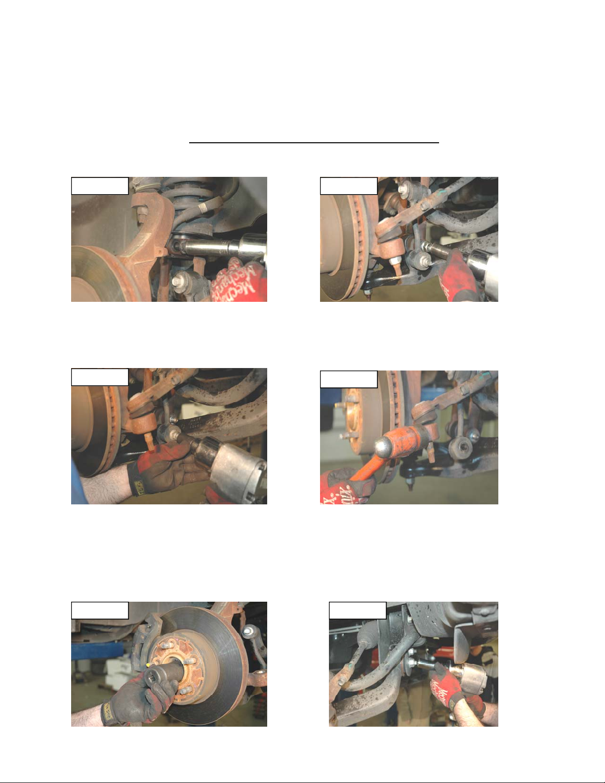
4. Using a 21mm deep-well socket remove the upper and lower strut fork nuts. See Figure 1 & 2.
Figure 1 Figure 2
5. Using a 18mm socket remove lower nuts from the sway bar links as shown in Figure 3. Then remove the
sway bar bolts and sway bar links. Retain for reuse.
6. Using a 19mm deep-well socket remove the tie-rod nut. Using a hammer hit the spindle as shown in Fig-
ure 4 until the tie-rod pops out. Never hit the tie-rod or the threaded shaft.
Figure 3
7. If you are working on a 4wd Liberty use a 36mm socket and remove the CV axle nut from the spindle. For
2wd this step will be skipped. See Figure 5. This is done to prevent any damage to the axle shaft from
over extension while installing the lift spacer.
8. Mark the lower control arm alignment cams and the lower arm. Loosen the Lower Control Arm Cam bolts
as shown in Figure 6 and adjust them so the bolts are towards the outside of the Liberty. Do not remove
these bolts.
Figure 5 Figure 6
Figure 4


9. Place the floor jack just under the Lower Control Arm. Remove the upper ball joint nut. Using a hammer
hit the spindle as shown until the ball joint breaks free. See Figure 7 & 8. Never hit the Ball Joint or the
threaded shaft.
Figure 7 Figure 8
10. Remove the lower factory bolt of the strut fork and remove it from the Liberty. It may be necessary to
spray penetrating fluid on the strut and hammer down on the fork to break it free.
11. Using a hand grinder, remove the spline on the stock strut body as shown in Figure 9.
Figure 9 Figure 10
12. Install the Strut Extension on the end of the fork as shown in Figure 10. Using a hammer tap the bottom
of the fork and install the spacer. Never hit the spacer directly.
13. Make sure the brake line is in front of the strut. If it is not route it there now. Using your hand push the
strut towards the inside of the Liberty. Look at the lower fork and Control Arm, these should be close to
aligning. If more drop is needed lower the floor jack.
14. With your hand push the strut inwards. See Figure 11. Use the alignment tool and from front to back
insert it though the front of the strut fork and then into the Lower Control Arm. Using the pry bar insert it
from the backside of the front fork and push inward on the back as shown in Figure 12. Once the rear
hole aligns insert the factory bolt. To align the front of the bolt reverse direction with the pry bar and tap
the bolt into place. See Figure 13. Install the factory nut but do not tighten at this time.
Figure 11 Figure 12


Figure 13
15. Lift the Lower Control Arm using the floor jack. As the Control Arm is moving up check clearance be-
tween the Strut Coil plate and the Unibody lip. If needed place the pry bar between them and continue
up. Stop going up once the upper ball joint goes into the spindle enough to start the nut. It may be nec-
essary to pry the upper control arm down to get the upper ball joint into the knuckle. See Figure 14.
Figure 14 Figure 15
17. Tighten the upper ball joint to factory specs.
18. Tighten the strut bolt to spacer and the strut bolt in the lower control arm to factory specs.
19. Install the tie-rod and nut to spindle and torque to factory specs. See Figure 15.
20. Install the CV shaft in to the knuckle and tighten nut to factory specs if vehicle is 4WD. See Figure 16.
Figure 16 Figure 17
21. Adjust the Lower Control Arm Cam bolts to the location marked in Step 8. Tighten to factory specs.
22. Install the tire and wheel.
23. Repeat all steps on Drivers side of vehicle.
24. With the Liberty still on the jack stands install the sway bar links on both sides using all factory hardware
and torque to factory specs. See Figure 17.
25. Using the floor jack lift the front of the Liberty and remove the jack stands. Lower the Liberty to the
ground. Turn the steering wheel left to right, lock to lock checking for interference of compone nts


REAR INSTALLATION
1. Chock the front wheels and jack up the rear of the Liberty. Place jack stands under the unibody frame
rails.
2. Using a 15mm socket remove the upper shock bolt. Using the 15mm and 18mm socket remove the
lower shock bolt. Remove the stock shock.
3. Remove the stock coil springs. Leave the stock bump stop in place.
4. Install the metal sleeve and small bushing on the top of the new Rough Country Shock as shown. Install
the top part of the shock as shown. Tighten to factory specs.
5. Install new coil springs small end towards the top.
6. Install the bottom of the new Nitro Shocks with factory bolts and tighten to factory specs
7. Using the floor jack lift the rear of the Liberty and remove the jack stands. Lower to the ground.
POST INSTALLTION NOTES
An alignment must be performed on vehicle after installation
Wheel lugs will need to retorqued after first 100 miles specs to factory specification.
Kit Contents:
2-Strut Extensions
2 Rear Gas Shocks
1 poly bag-Shock Hardware
1 Warning to Driver Decal
1 Rough County Windshield Decal
Tools Needed:
22mm Deep Well 19mm Deep Well
24mm Deep Well 24mm Wrench
15mm Deep Well 18mm Deep Well
Hammer Med. Alignment Spike
Floor Jack Pry bar
36mm Hub Socket 10mm Wrench
1/2” Ratchet 2 Jack Stands

 Loading...