

Page 1

9266400
06-UP JEEP COMMANDER 2” LIFT KIT
Thank you for choosing Rough Country for all your suspension needs.
Rough Country recommends a certified technician install this system. In addition to these instructions, professional
knowledge of disassemble/reassembly procedures as well as post installation checks must be known. Attempts to install
this system without this knowledge and expertise may jeopardize the integrity and/or operating safety of the vehicle.
Please read instructions before beginning installation. Check the kit hardware against the parts list on this page. Be sure
you have all needed parts and know where they go. Also please review tools needed list and make sure you have
needed tools.
As a general rule, the taller a vehicle is, the easier it will roll. Seat belts and shoulder harnesses should be worn at all
times. Avoid situations where a side rollover may occur.
Generally, braking performance and capability are decreased when larger/heavier tires and wheels are used. Take this
into consideration while driving. Do not add, alter, or fabricate any factory or after-market parts to increase vehicle height
over the intended height of the Rough Country product purchased. Mixing component brands is not recommended.
Rough Country makes no claims regarding lifting devices and excludes any and all implied claims. We will not be responsible for any product that is altered.
If questions exist we will be happy to answer any questions concerning the design, function, and correct use of our products.
This suspension system was developed using a 265/70R-17 tire with factory wheels. Note if wider tires are used, offset
wheels will be required and trimming will be required.
NOTICE TO DEALER AND VEHICLE OWNER
Any vehicle equipped with any Rough Country product should have a “Warning to Driver” decal installed on the inside of
the windshield or on the vehicle’s dash. The decal should act as a constant reminder for whoever is operating the vehicle of its unique handling characteristics.
INSTALLING DEALER - it is your responsibility to install the warning decal and forward these installation instructions on
to the vehicle owner for review. These instructions should be kept in the vehicle for its service
PRODUCT USE INFORMATION
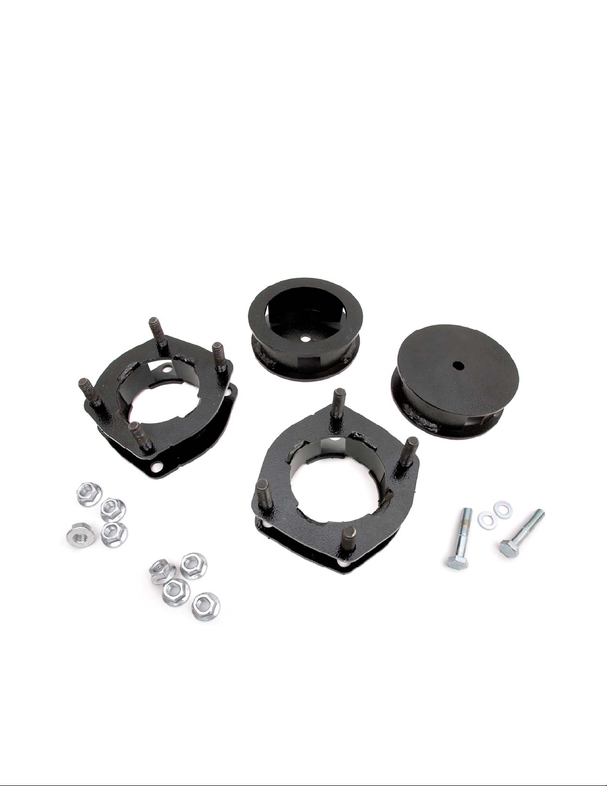
Kit Contents:
664 Kit Box
2– Front Coil Spring Spacers
2– Rear Coil Spring Spacers
1-Poly Bag
Tools Needed:
10mm Wrench
14mm Socket
16mm Wrench
16mm Socket
18mm Wrench
18mm Socket
19mm Deep Well Socket
Jack
Jack Stands
Hand Grinder
Strut Compressor
Torque Specs:
Size Grade 5 Grade 8
5/16” 15 ft/lbs 20 ft/lbs
3/8” 30 ft/lbs 35 ft/lbs
7/16” 45 ft/lbs 60 ft/lbs
1/2” 65 ft/lbs 90 ft/lbs
9/16” 95 ft/lbs 130 ft/lbs
5/8” 135 ft/lbs 175 ft/lbs
3/4” 185 ft/lbs 280 ft/lbs
Class 8.8 Class 10.9
6MM 5 ft/lbs 9 ft/lbs
8MM 18ft/lbs 23 ft/lbs
10MM 32ft/lbs 45ft/lbs
12MM 55ft/lbs 75ft/lbs
14MM 85ft/lbs 120ft/lbs
16MM 130ft/lbs 165ft/lbs
18MM 170ft/lbs 240ft/lbs
Page 2
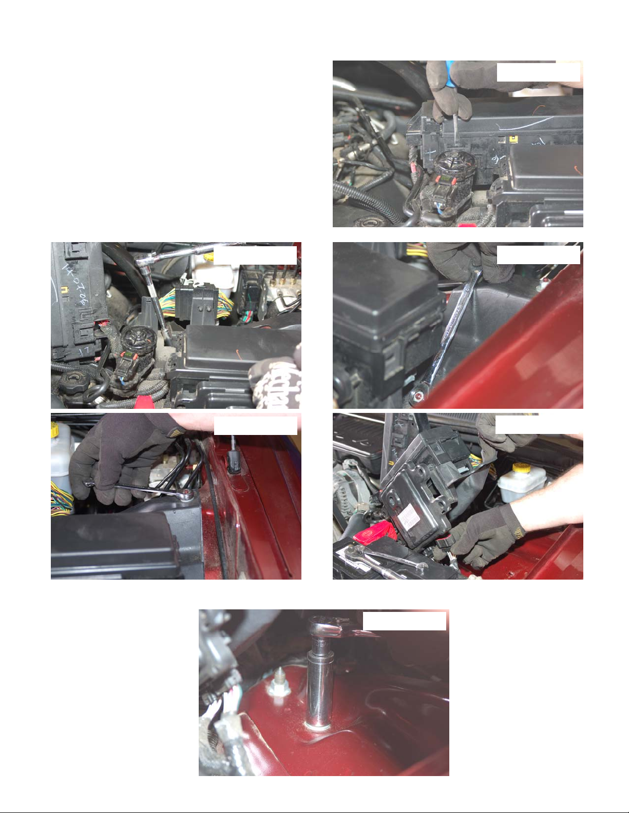
FRONT INSTALLATION INSTRUCTIONS
1. Jack up the front of the vehicle and support the vehicle with
jack stands, so that the front wheels are off the ground.
Chock rear wheels.
2. Remove the front tires/wheels
socket.
3. Support the Drivers side lower control arm with a floor jack.
4. Remove the positive wire from the battery terminal.
5. On the driver side remove the rear most box from the
mount by releasing the clips from the box as shown in
Photo 1. Take care not to damage the clip or the box.
6. Carefully fold the box over to access the mount bolts with a
10mm socket /wrench as shown in Photo 2, 3 & 4.
7. Carefully lift the forward fuse box on the driver side of the
engine compartment and release the wiring clips. Take
care not to damage the clips. See Photo 5.
, using a 19 mm deep well
PHOTO 2
PHOTO 1
PHOTO 3
PHOTO 4
6. With the floor jack under the lower drivers side lower control ,remove the 4 stock nuts that secure the strut to the upper mount as shown using a 18mm socket/wrench. Retain the hardware for reuse. See Photo 6.
PHOTO 6
PHOTO 5
Page 3
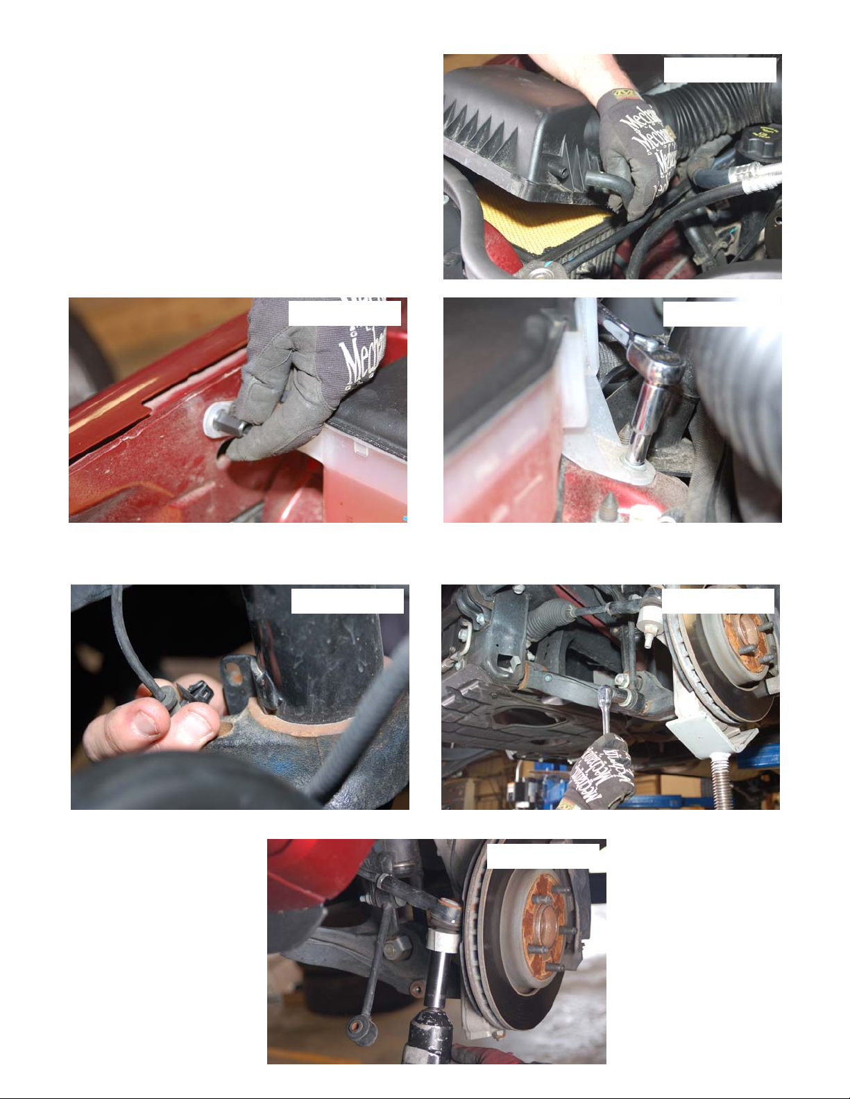
7. Gently lower the floor jack under the front driver side and
place it under the passenger side lower control arm of the
vehicle.
8. Release the air box clamps that secure the top of the air
box to the bottom and remove the hose as shown in
Photo 7. Lift the air box out of the air box mount.
9. On the Passenger side remove the washer tank by
removing the plastic nut by hand and removing the rear
mount bolt using a 8mm socket/ wrench. See Photo 8 &
9.
10. Position washer tank out of the way to allow access to the
upper strut bolts.
11. Remove the upper strut nuts using a 18mm socket /
wrench. Retain the factory hardware for reuse. Lower the
floor jack gently to lower the strut from the mount.
PHOTO 7
PHOTO 8
PHOTO 9
12. Starting on the drivers side remove the wire clip from the strut as shown in Photo 10.
13. Remove the sway bar from the control arm as shown in Photo 11 using a 18mm socket. Retain the hardware for
reuse.
PHOTO 10 PHOTO 11
14. Remove the tie rod from the knuckle as shown using a 21mm socket/wrench. See Photo 12. Retain hardware.
PHOTO 12
Page 4
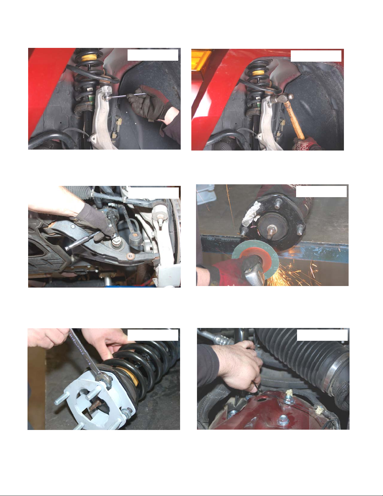
15. Loosen the upper ball joint nut as shown with a 18mm wrench. Do not totally remove the upper ball joint nut at this
time. Using a hammer slightly tap the upper tie rod mount to loosen taper. See Photo 13 & 14. Position knuckle to
allow for strut removal.
PHOTO 13
PHOTO 14
16. Remove the lower strut hardware as shown in Photo 15 using a 24mm socket/wrench and remove the strut from
the vehicle.
17. Using a hand grinder or similar tool, grind the unthreaded tip portion of the factory stud to allow cl earance on the
new upper strut spacer. Take care not to damage the stud threads. See Photo 16.
PHOTO 15
PHOTO 16
18. Install the new spacer as shown with factory hardware using a 18mm wrench. A strut compressor will ease the reinstallation of the strut assembly. It will be necessary to start all 4 of the stock nuts before totally tightening the
spacer to the strut. See Photo 17.
19. Reinstall the strut and spacer assembly back in the factory upper strut mount using the supplied 12mm flange
nuts. Do not tighten at this time. See Photo 18.
PHOTO 17
PHOTO 18
Page 5
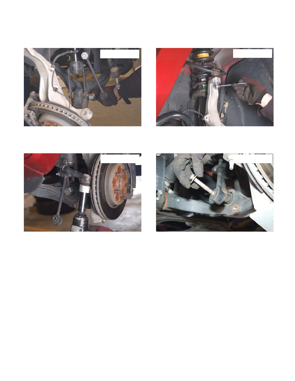
20. Swing the lower control arm up and reinstall the lower strut mount in the stock location on the lower control arm
using the factory hardware. Tighten with a 24mm socket/wrench. Tighten upper strut mount using 18mm socket/
wrench. See Photo 19.
21. Jack up the lower control arm and reinstall the knuckle to the upper ball joint with stock hardware using a 18mm
wrench. See Photo 20.
PHOTO 19
PHOTO 20
22. Reinstall the tie rod to the knuckle with factory hardware using a 21mm socket / wrench. See Photo 21.
23. Repeat process for the passenger side.
24. Reattach the sway bar to the driver and passenger side lower control arm with the factory hardware and using a 18
socket. See Photo 22.
PHOTO 21 PHOTO 22
25. After strut spacer installation has been completed, Reinstall the washer fluid tank and air box on the passenger side
with the factory hardware using a 8mm socket / wrench.
26. Reinstall the electrical boxes on the driver side with factory hardware using a 10mm wrench / socket.
27. Reinstall the tires/ wheels.
28. Jack up the vehicle and remove the jack stands,.
29. Lower the vehicle to the ground.
Page 6
REAR INSTALLATION INSTRUCTIONS
1. Jack up the rear of the vehicle and support the vehicle with jack stands, so that the rear wheels are off the ground.
Chock front wheels.
2. Remove the rear tires/wheels
3. Support the rear axle with a floor jack.
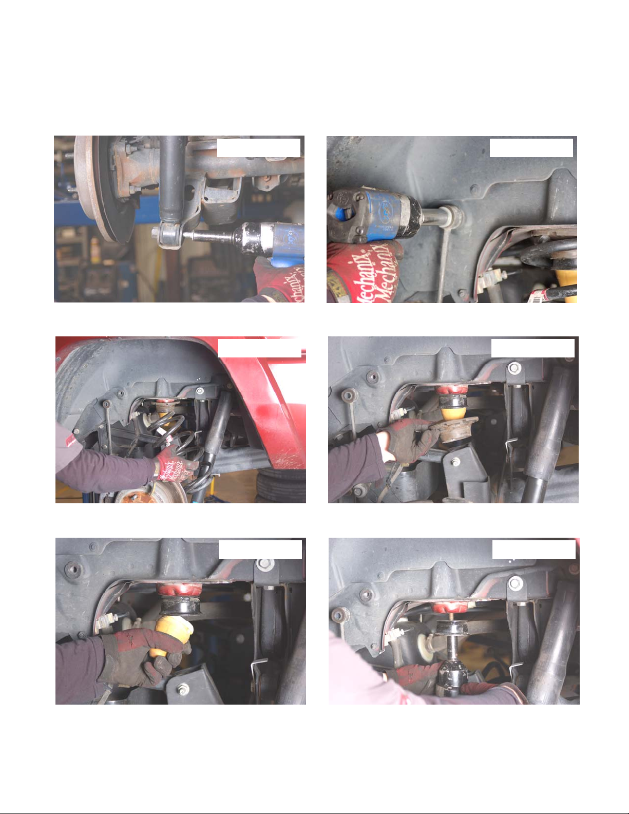
4. Remove the shock from the rear lower mount as shown in Photo 23 using a 15mm socket/ wrench.
5. Remove the bolt from the upper sway bar mount on the frame using a 18mm socket / wrench as shown in Photo 24.
6. Lower the rear end with the floor jack and remove the coil spring. See Photo 25.
7. Remove the stock upper coil isolator and retain for reuse. See Photo 26.
, using a 19mm deep well socket.
PHOTO 23 PHOTO 24
PHOTO 25 PHOTO 26
8. Remove the bump stop as shown in Photo 27 and remove the bump stop cup from the frame using a 15mm socket.
See Photo 28.
PHOTO 27 PHOTO 28
Page 7
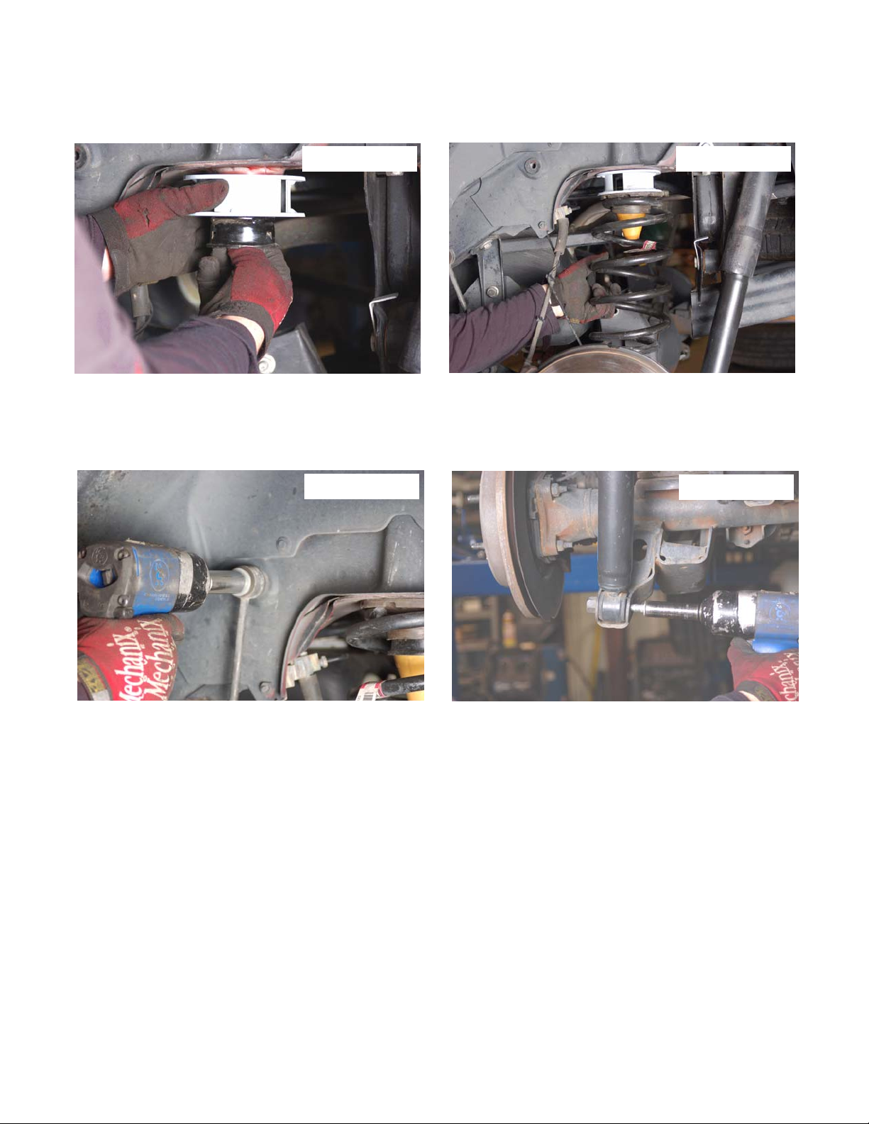
9. Install the bump stop bracket on the new spacer as shown with supplied 10mm x 55mm bolt & washers using a
15mm socket. See Photo 29. Tighten 10mm bolt to 32ft/lbs. Do not over-tighten bolt.
10. Reinstall the factory bump stop in the bump stop cup and coil spring as shown in Photo 30 in the stock location with
the stock rubber on the top of the coil spring. It may be necessary to remove the upper control arm from the
upper mount to allow the coil to be installed. If needed remove the bolt with a 18mm socket / wrench.
PHOTO 29 PHOTO 30
11. If removed, reinstall the upper control arm bolt at this time using a 18mm socket. Raising or lowering the floor jack
may be needed to align the control arm to the mount.
12. Reinstall the sway bar link on the frame with factory hardware using a 18mm socket / wrench. See Photo 31.
13. Reinstall the lower shock in the lower shock mount with the factory hardware using a 15mm socket / wrench. See
Photo 32.
PHOTO 31
14. Reinstall the tires & wheels.
15. Jack up the rear of the vehicle and remove the jack stands.
16. Lower the vehicle to the ground.
PHOTO 32
Page 8
POST INSTALLATION INSTRUCTIONS
1. Check all fasteners for proper torque. Check to ensure there is adequate clearance between all rotating, mobile,
fixed and heated members. Check steering for interference and proper working o rder. Test brake system.
2. Perform steering sweep. The distance between the tire sidewall and the brake hose must be chec ked closely. Cycle
the steering from full turn to full turn to check for clearance. Failure to perform inspections may result in component
failure.
3. Re torque all fasteners after 500 miles. Visually inspect components and re torque fasteners during routine vehicle
service.
4. Readjust headlights to proper settings.
KIT CONTENTS
Thank you for choosing Rough Country for all your suspension needs
 Loading...