

Page 1
E-M-HW4v3-F2-021_10
Document code Unit
Rotronic AG
Bassersdorf, Switzerland
HW4 software v.3: Device Manager and Data
Logging LOG-RC Series Data Loggers
Document title
HW4 Software version 3
Device Manager and Data Logging
LOG-RC Series Data Loggers
Instruction Manual
Page
1 of 18
Document Type
© 2011; Rotronic AG E-M-HW4v3-F2-021_10
Page 2

E-M-HW4v3-F2-021_10
Document code Unit
Rotronic AG
Bassersdorf, Switzerland
HW4 software v.3: Device Manager and Data
Logging LOG-RC Series Data Loggers
Document title
Instruction Manual
Page
2 of 18
Document Type
Table of contents
1 ORGANIZATION OF THE HW4 MANUALS ....................................................................................... 3
2 OVERVIEW ......................................................................................................................................... 4
3 INITIAL SETUP ................................................................................................................................... 4
3.1 USB dongle wireless adapter ............................................................................................................. 4
3.2 LAN wireless adapter ......................................................................................................................... 5
4 SEARCHING FOR THE WIRELESS ADAPTER AND DATA L OGGERS .......................................... 6
4.1 Adapters Tab ..................................................................................................................................... 7
4.2 Devices Tab ....................................................................................................................................... 9
4.3 Signal Strength Tab ..........................................................................................................................10
5 HW4 Device Tree ............................................................................................................................. 11
6 DEVICE MANAGER .......................................................................................................................... 11
6.1 Device Manager Form Menu Bar ......................................................................................................12
6.2 Device Information ............................................................................................................................13
6.3 Settings .............................................................................................................................................14
7 DATA LOGGING ............................................................................................................................... 16
7.1 Data Logging Form Menu Bar ...........................................................................................................17
7.2 Adding a calculated parameter to the log file ....................................................................................17
8 DOCUMENT RELEASES.................................................................................................................. 18
© 2011; Rotronic AG E-M-HW4v3-F2-021_10
Page 3
E-M-HW4v3-F2-021_10
HW4 Manuals
Contents
General software description
Functions common to all devices used with HW4
Legacy devices (original HygroClip technology):
specific functions
Humidity and temperature adjustment f un ctio n common to
all legacy devices (original HygroClip technology)
Devices based on the AirChip 3000 technology:
functions
Humidity and temperature adjustment f un ctio n common to
all devices based on the AirChip 3000 technology
Data recording function common to all devices based on the
AirChip 3000 technology
Document code Unit
Rotronic AG
Bassersdorf, Switzerland
HW4 software v.3: Device Manager and Data
Logging LOG-RC Series Data Loggers
Document title
Instruction Manual
Page
3 of 18
Document Type
1 ORGANIZATION OF THE HW4 MANUALS
The HW4 manuals are organized in separate books so as to limit the size of the individual documents. A list
of the HW4 manuals is provided in document E-M-HW4v3-DIR
HW4 Main Book
Device Specific Functions 1
(separate book for each device type or model)
Installation, start-up and settings
Device connection methods
o HygroLog NT data logger
o HygroFlex 2, HygroFlex 3 and M3 transmitters
(same icon in device tree)
o HygroLab 2 and HygroLab 3 bench indicators
o HygroPalm 2 and HygroPalm 3 portable indicators
o HygroClip DI digital interface
o HygroClip Alarm programmable logic
o HygroStat MB
Device Manager (device configuration) and other device
Probe Adjustment 1
Device Specific Functions 2
(separate book for each device type or model)
Probe Adjustment 2
Data Recording Function
Both the HW4 manuals (software) and device specific manuals (hardware) are available from the HW4 CD.
The manuals can also be downloaded from several of the ROTRONIC web sites.
o HygroClip 2 (HC2) probes
o HF3 transmitters and thermo-hygrostats
o HF4 transmitters
o HF5 transmitters
o HF6 transmitters
o HF7 transmitters
o HL20 and HL21 data loggers
o HP21, HP22 and HP23 hand-held indicators
o HygroLab C1 table-top indic ator
o LOG-RC Series Data Loggers
o Custom designed OEM products
Device Manager (device configuration) and Data Logging
© 2011; Rotronic AG E-M-HW4v3-F2-021_10
Page 4
E-M-HW4v3-F2-021_10
HW4 Functional Modules
LOG-RC Series Data Loggers
o User configurable settings for the data loggers and
associated accessories
Data Logging
o Memory status, log interval setting and data download
Document code Unit
Rotronic AG
Bassersdorf, Switzerland
HW4 software v.3: Device Manager and Data
Logging LOG-RC Series Data Loggers
Document title
Instruction Manual
Page
4 of 18
Document Type
2 OVERVIEW
This section of the HW4 manual covers only the following HW4 modules:
Usage
Device Manager
o Calibration / Adjustment: HW4 does not allow calibrating or adjusting the LOG-RC series data loggers.
The HygroClip probe that is used with model LOG-HC2-RC cannot be calibrated or adjusted while
connected to the data logger. HW4 can be used to calibrate and adjust a HygroClip probe that is directly
connected to the HW4 PC by means of a service cable such as cable AC3001. For instructions, please
see the HW4 manual E-M-HW4v3-A2-001
o HW4 functions that are not device dependent are cov ered in the H W4 manual E-M-HW4v3-Main.
3 INITIAL SETUP
The LOG-RC series data loggers use the following radio frequencies to communicate with the HW PC:
433.92 MHz (standard) or 915 MHz (USA).
Communication with the HW4 PC requires one of the following types of adapter:
o USB dongle wireless adapter
o LAN wireless adapter (Ethernet – TCP/IP protocol)
In principle, you may use as many LAN adapters as required by your application but you can only one USB
dongle adapter.
3.1 USB dongle wireless adapter
The USB dongle wireless adapter requires a driver in order to communicate with the HW4 PC.
IMPORTANT:
o Do not run HW4 while installing this driver
o Do not plug-in the USB dongle to the HW4 PC before installing the driver
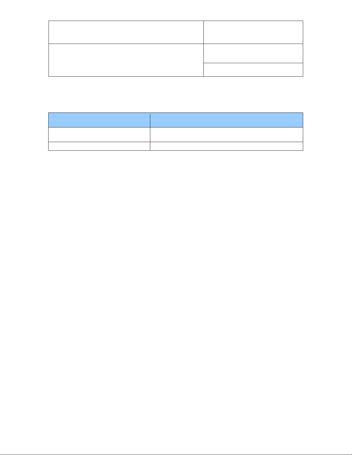
3.1.1 USB Driver installation
As part of its installation process, the HW4 installer creates a directory labeled “USB_Driver_LOG-xxx-RC”
located in the HW4 installation folder:
© 2011; Rotronic AG E-M-HW4v3-F2-021_10
Page 5
E-M-HW4v3-F2-021_10
Document code Unit
Rotronic AG
Bassersdorf, Switzerland
HW4 software v.3: Device Manager and Data
Logging LOG-RC Series Data Loggers
Document title
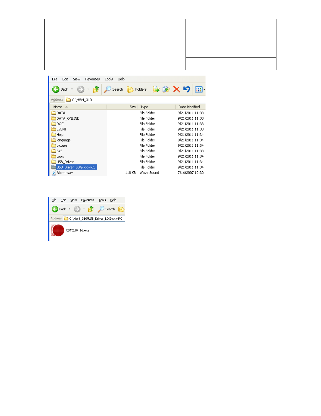
Open the directory and double click on the file named CDM2.04.16.exe. This automatically installs on the
HW4 PC the driver required to use USB dongle wireless adapter
Instruction Manual
Page
5 of 18
Document Type
At this point you can plug-in the USB dongle wireless adapter to the HW4 PC and Windows should
automatically associate the driver to the USB dongle. When this is done you can run HW4 and search for
any available data logger as explained later on in this manual.
3.2 LAN wireless adapter
The LAN adapter is factory configured to use DHCP (Dynamic Host Configuration Protocol) and should be
used only on a LAN that includes a DHCP server such as a router or a managed switch.
With DHCP enabled, the DHCP server senses when a new device (or host) is connected to the network and
automatically assigns / configures the device with the next available IP address. The device is also
automatically configured with the network subnet mask and gateway address. Using DHCP is simple,
guarantees compatibility with the network and eliminates the possibility of conflicting IP addresses.
An IP address assigned using DHCP is also known as a dynamic address. As long as DHCP remains
enabled on the host, the host IP address is subject to change. This is not desirable when using HW4.
Once the dynamic address of the host is known, and communication with the host can be established, we
recommend to change the host IP address to an unused network address and to disable DHCP on the host.
In this manner, the new host IP address is a static address, not subject to change.
When using more than one LAN adapter, make sure to give each one a unique name (or network name).
See further down in this manual for instructions.
© 2011; Rotronic AG E-M-HW4v3-F2-021_10
Page 6
E-M-HW4v3-F2-021_10
Document code Unit
Rotronic AG
Bassersdorf, Switzerland
HW4 software v.3: Device Manager and Data
Logging LOG-RC Series Data Loggers
Document title
Instruction Manual
Page
6 of 18
Document Type
4 SEARCHING FOR THE WIRELESS ADAPTER AND DATA
LOGGERS
Do one of the following:
o Connect the USB dongle wireless adapter to the HW4 PC (after having installed the required USB
driver)
or
o Power up the LAN wireless adapter and connect it to the same LAN as the HW4 PC.
Note: in principle there is no limit as to the number of adapters that can be simultaneously used. However
only a single USB dongle adapter is permitted.
The Rotronic wireless data loggers are set by the factory to automatically transmit measurement data
whenever interrogated by HW4. Initially, make sure that the data loggers are within a few meters (or yards)
of the wireless adapter.
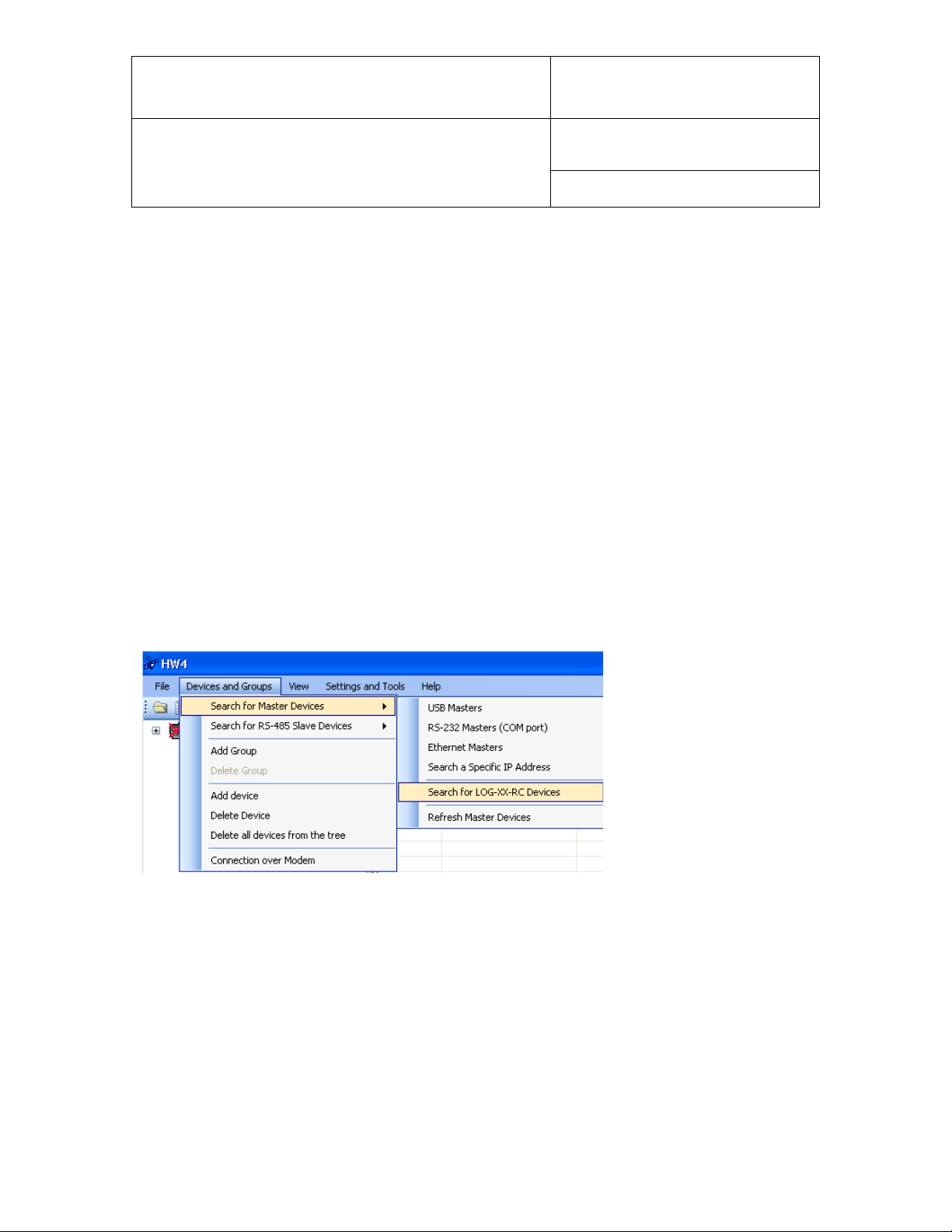
Start HW4 and use the HW4 main menu bar as illustrated below:
© 2011; Rotronic AG E-M-HW4v3-F2-021_10
Page 7
E-M-HW4v3-F2-021_10
Document code Unit
Rotronic AG
Bassersdorf, Switzerland
HW4 software v.3: Device Manager and Data
Logging LOG-RC Series Data Loggers
Document title
Click on “Search for LOG-XX-RC” to open the Search for Wireless Devices form.
The form has 3 tabs labeled “Devices”, Adapters” and
“Signal Strength”.
Instruction Manual
Page
7 of 18
Document Type
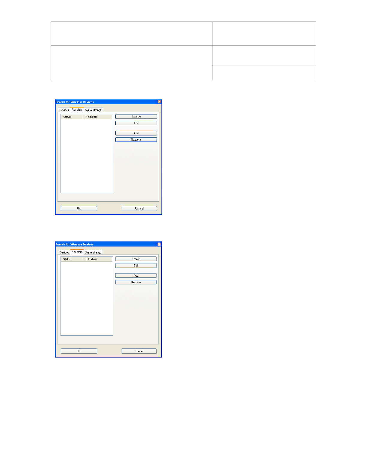
4.1 Adapters Tab
The “Adapters” tab has 4 buttons located on the right hand side:
o Search: click on this button to detect any adapter (LAN or USB)
o Edit: this button works only with a LAN adapter and opens a form that can be used to change the
network settings of the adapter
o Add: use this button to add a LAN adapter with a known IP address
o Remove: use this button to remove the selected adapter from the form
The adapters detected by HW4 are listed on the left hand side of the form. Any adapter can be selected by
clicking on it with the mouse.
© 2011; Rotronic AG E-M-HW4v3-F2-021_10
Page 8

E-M-HW4v3-F2-021_10
Document code Unit
Rotronic AG
Bassersdorf, Switzerland
HW4 software v.3: Device Manager and Data
Logging LOG-RC Series Data Loggers
Document title
LAN Wireless Adapter USB Dongle Wireless Adapter
Page
Instruction Manual
Document Type
8 of 18
The status reads “OK” when the adapter is working and when the HW4 PC can communicate with it. When a
previously detected adapter can no longer be found, the status reads “unknown”. In the case of a LAN
adapter the form shows the IP address of the adapter. Whenever the IP address of a LAN adapter is not
compatible with the LAN the status reads “invalid IP”. In this case the adapter should be reconfigured as
explained below.
4.1.1 Reconfiguring a LAN adapter
Select the “Adapters” tab and highlight the LAN adapter by clicking on it the mouse
With the adapter selected, click on the “Edit” button and use the
form shown to the left to change the adapter network settings.
© 2011; Rotronic AG E-M-HW4v3-F2-021_10
Page 9
E-M-HW4v3-F2-021_10
Document code Unit
Rotronic AG
Bassersdorf, Switzerland
HW4 software v.3: Device Manager and Data
Logging LOG-RC Series Data Loggers
Document title
Instruction Manual
Page
9 of 18
Document Type
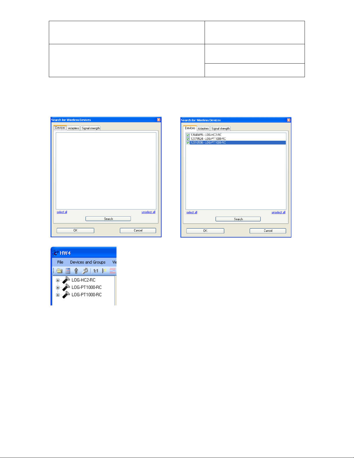
4.2 Devices Tab
The Devices Tab is used to make HW4 detect the wireless data loggers that are currently communicating
with the wireless adapter(s). To do this, click on the “Search” button located at the bottom of the form.
The “OK” button is used to add the selected data loggers to the HW4 Device
Tree as illustrated below.
Any device can be individually selected by clicking on the box located to the
left of the device (a check mark appears). All devices can also be globally
selected or de-selected.
© 2011; Rotronic AG E-M-HW4v3-F2-021_10
Page 10

E-M-HW4v3-F2-021_10
Document code Unit
Rotronic AG
Bassersdorf, Switzerland
HW4 software v.3: Device Manager and Data
Logging LOG-RC Series Data Loggers
Document title
Instruction Manual
Page
10 of 18
Document Type
4.3 Signal Strength Tab
This tab is used to visualize the strength of the radio signal received by each adapter from the wireless data
loggers.
o Click on one of the available adapters to select it
o Click on the button labeled “Show Devices”
o Click on any device to select it and display the signal strength bar chart.
© 2011; Rotronic AG E-M-HW4v3-F2-021_10
Page 11
E-M-HW4v3-F2-021_10
Document code Unit
Rotronic AG
Bassersdorf, Switzerland
HW4 software v.3: Device Manager and Data
Logging LOG-RC Series Data Loggers
Document title
Instruction Manual
Page
11 of 18
Document Type
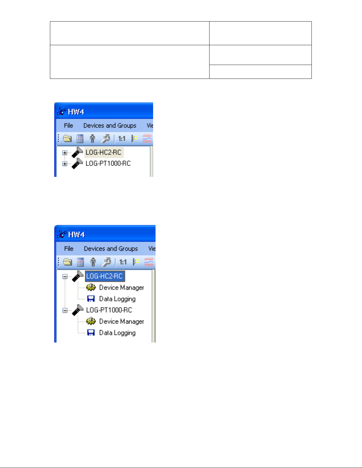
5 HW4 Device Tree
When HW4 has detected one or several wireless data loggers
each device appears as an icon in the left pane of the HW4
main screen.
Click on the + sign to the left of any of the icons to display a list
of the available functional modules (see below).
6 DEVICE MANAGER
The Device Manager module is used to configure the data loggers.
To select the Device Manager module, click on it with the left
mouse button. HW4 opens the Device Manager form.
Device Manager automatically interrogates the d ata logg er
and downloads its current configuration.
© 2011; Rotronic AG E-M-HW4v3-F2-021_10
Page 12

E-M-HW4v3-F2-021_10
Document code Unit
Rotronic AG
Bassersdorf, Switzerland
HW4 software v.3: Device Manager and Data
Logging LOG-RC Series Data Loggers
Document title
Instruction Manual
Page
12 of 18
Document Type
The different sub-forms that are available within the Device Manager form are listed in a tree located on the
left pane of the form. To select a sub-form, click on it with the left mouse button.
6.1 Device Manager Form Menu Bar
The Device Manager Menu ba r is located at the top of the for m.
File
● Close: closes the form
Tools
● Generate Protocol: generates a Device Configuration Protocol. This text file is automatically saved in
the folder specified in HW4 Global Settings - File Locations Tab. If so desired, any directory and any file
type may be specified. T his ac tion is not recorded in the User Event file.
Help:
● HW4 Help: Opens HW4 Help
● About HW4: Displays the version number and ID number of HW4
© 2011; Rotronic AG E-M-HW4v3-F2-021_10
Page 13

E-M-HW4v3-F2-021_10
Document code Unit
Rotronic AG
Bassersdorf, Switzerland
HW4 software v.3: Device Manager and Data
Logging LOG-RC Series Data Loggers
Document title
6.2 Device Information
Instruction Manual
Page
13 of 18
Document Type
● Device Protection: This function is used to prevent unauthorized access to critical functions such as
configuration changes, humidity and temperature adjustment, etc. Click on the blue link labeled
“Change” to activate or deactivate the device protection. The password is the 4 character access code
that can be read from a sticker located on the device.
Click on the Device Manager OK button to confirm the protection settings to the data logger.
● Set Date /Time: click on this link to set the date and time of the data logger to the date and time of the
HW4
© 2011; Rotronic AG E-M-HW4v3-F2-021_10
Page 14

E-M-HW4v3-F2-021_10
Document code Unit
Rotronic AG
Bassersdorf, Switzerland
HW4 software v.3: Device Manager and Data
Logging LOG-RC Series Data Loggers
Document title
6.3 Settings
The contents of this form depends on the model of data logger
LOG-HC2-RC Settings
Instruction Manual
Page
14 of 18
Document Type
LOG-PT1000-RC Settings
● Device Name: As far as possible use a unique device name (maximum 12 characters)
© 2011; Rotronic AG E-M-HW4v3-F2-021_10
Page 15

E-M-HW4v3-F2-021_10
Document code Unit
Rotronic AG
Bassersdorf, Switzerland
HW4 software v.3: Device Manager and Data
Logging LOG-RC Series Data Loggers
Document title
● Data Transmission:
Off: the data logger does not send measurement data when polled by HW4. Device Manager and Data
Logging are still fully functional
Solicited Mode: select this data transmission mode if you wish to display the measurement data on the
HW4 main screen. In this mode the data logger sends measurement only when solicited by HW4 via the
wireless adapter. Measurement data cannot be sent by the data logger any faster than once every
minute. This means that when the HW4 polling interval is less than one minute, measurement data is
received from the data logger only once every minute. To set the HW4 polling interval: use the HW4
Main Menu Bar > Settings and Tools > HW4 Global Settings > General Tab. It is important to note that
the measurement data sent by the data logger is refreshed only at the rate of the log interval used by
the logger (see Data Recording in this manual). Both the HW4 polling interval and the data logger log
interval should be set by the user so as to conserve battery power.
Unsolicited Mode: the data logger automatically sends measurement data every 6 seconds. This data
transmission mode is meant for use with data logger model LOG-GPRS-RC (under development)
● Fixed Pressure: use this fie ld to enter a numerical value for calculated psychrometric parameters that
require barometric pressure as an input value.
● Calculation: Left click on the arrow to the right of the text box and select from the following: No
calculation, Dew Point, Frost Point or other psychrometric parameter. Please note that the data logger
itself does not perform any calculation and that the calculation setting is not retained in the data logger.
The calculation setting must be re-entered whenever the data logger is deleted from the Device Tree
and is searched again.
● Lo-Alarm, Hi-Alarm, Hysteresis: Alarm conditions can be defined for humidity, temperature and the
calculated parameter. Values that are below the low alarm value or above the high alarm value will
trigger an alarm. The value specified for the alarm function hysteresis is used for both the low and the
high alarm. To enable the alarm function click on the box located to the left of each parameter that you
wish to monitor. A check mark appears in the box when monitoring is enabled.
All versions of HW4 show an out-of-limits value alarm by using red characters on the monitor screen. In
addition, HW4 Professional can be configured (HW4 global settings - Alarm settings tab) to display an
alarm table and generate a report whenever an out-of-limits condition occurs
Please note that the data logger itself does not monitor alarm conditions and that alarm settings are not
retained in the data logger. The alarm settings must be re-entered whenever the data logger is deleted
from the Device Tree and is searched again.
Instruction Manual
Page
15 of 18
Document Type
6.3.1 Unit system
The unit system (metric / English) for both the measurement data displayed by HW4 and the recorded data
downloaded to theHW4 PC is determined by the HW4 Global Settings (HW4 main menu bar > Settings and
Tools > HW4 Global Settings, Language / Unit System tab)
© 2011; Rotronic AG E-M-HW4v3-F2-021_10
Page 16
E-M-HW4v3-F2-021_10
Document code Unit
Rotronic AG
Bassersdorf, Switzerland
HW4 software v.3: Device Manager and Data
Logging LOG-RC Series Data Loggers
Document title
Instruction Manual
Page
16 of 18
Document Type
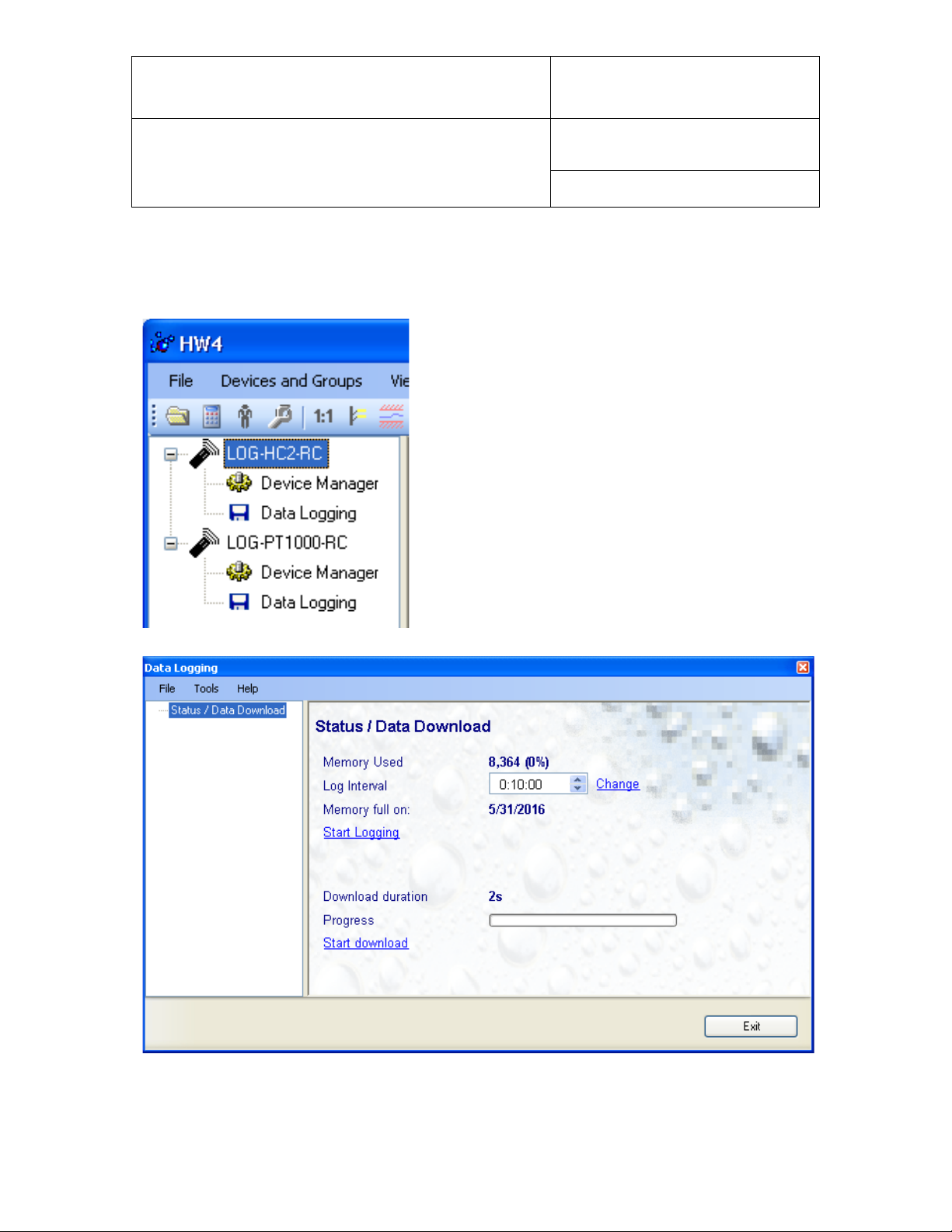
7 DATA LOGGING
The Data Logging module is used to set the log interval, download the recorded data to the HW4 PC and
clear the memory.
To select the Data Logging module, click on it with the left
mouse button. HW4 opens the Data Logging form.
.
Note: this series of data loggers is designed to record data continuously until the memory becomes full. No
data recording stop function is provided.
© 2011; Rotronic AG E-M-HW4v3-F2-021_10
Page 17

E-M-HW4v3-F2-021_10
Document code Unit
Rotronic AG
Bassersdorf, Switzerland
HW4 software v.3: Device Manager and Data
Logging LOG-RC Series Data Loggers
Document title
o Log interval: 5 seconds to 12 hours, in 5 seconds increments.
o Change : click on this link to write the value of the log interval to the data logger
NOTE: Based on both the memory size and on the log interval, the form provides an estimate of the date
when the memory will be full. At that time the data logger will stop recording data. The estimated date does
not take into account the remaining battery lifetime or the effect of the log interval value on the battery
power.
o Start Logging: click on this link to erase the memory contents and start recording a new set of
measurement data
o Start Download: click on this link to download and view the recorded data. The type of file used for
storing the recorded data on the HW4 PC can be set from the menu bar of the Data Logging form
(Tools > File Format)
Instruction Manual
Page
17 of 18
Document Type
7.1 Data Logging Form Menu Bar
The Data Logging menu bar is located at the top of the form.
File
● Exit: This menu item closes the for m
Tools
● File Format: use this menu item to set the file format (text file - .txt or binary - .log) that HW4 uses
when saving the data to disk.
● Generate Protocol: generates a Log Settings Protocol. This text file is automatically saved in the folder
specified in HW4 Global Settings - File Locations Tab. If so desired, any directory and any file type may
be specified. This action is not recorded in the User Event file.
Help:
● HW4 Help: Opens HW4 Help
● About HW4: Displays the version number and ID number of HW4
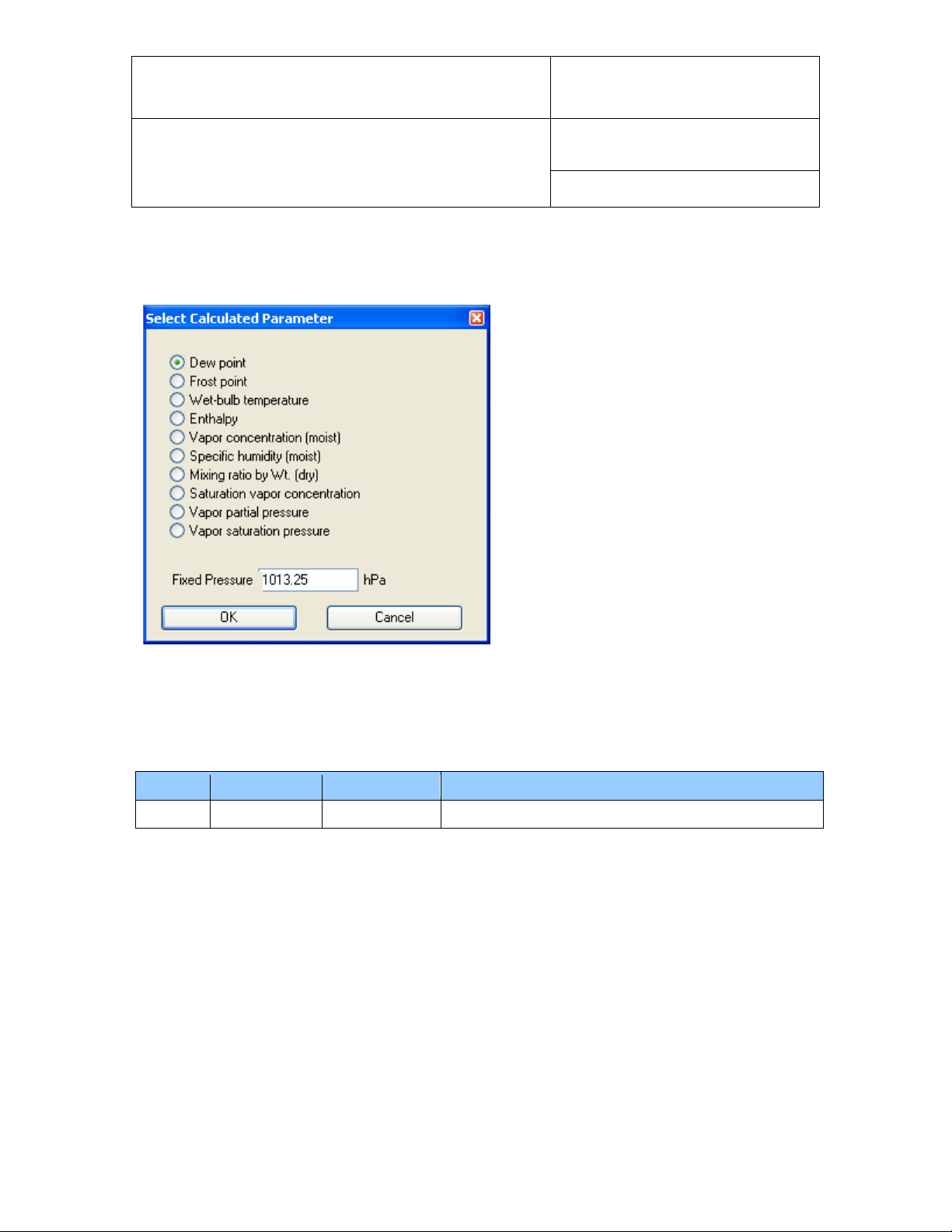
7.2 Adding a calculated param e ter t o t he l og file
HW4 View Data can be used to add a calculated parameter such as dew point to a log file comprised of
relative humidity and temperature records. The parameter is calculated for each data record based on the
relative humidity and temperature values.
HW4 View Data can also be used to replace the calculated parameter in a log file with a different one.
© 2011; Rotronic AG E-M-HW4v3-F2-021_10
Page 18
E-M-HW4v3-F2-021_10
_10
3.1.0
Oct. 31, 2011
Original release
Document code Unit
Rotronic AG
Bassersdorf, Switzerland
HW4 software v.3: Device Manager and Data
Logging LOG-RC Series Data Loggers
Document title
HW4 View Data opens automatically after downloading data from the data logger. Files that have already
been downloaded can be opened from the HW4 main menu bar by selecting File > Open.
To access the “Add / Change calculated parameter” function, click on Tools in the HW4 View Data menu
bar and select “Add / Change calculated parameter”. This opens the following form:
Use the form shown on the left to select one of
the available calculated par a m eters.
NOTE: some parameters such as Enthalpy,
Mixing Ratio etc. require barometric pressure as
a calculation input. Be sure to enter the correct
pressure value in the form.
Click on the OK button to add the selected calculated parameter or change the existing calculated
parameter.
Instruction Manual
Page
18 of 18
Document Type
8 DOCUMENT RELEASES
Release Software Ver. Date Notes
© 2011; Rotronic AG E-M-HW4v3-F2-021_10
 Loading...