

Page 1
© 2018 ROTRONIC AG Bassersdorf Switzerland
RMS Wall mount Data Logger
Page 2

RMS-LOG Wireless / LAN Data Loggers
E-M-RMS-LOG-V1.4.docx
Instruction Manual
© 2018 ROTRONIC AG Bassersdorf Switzerland Page 2 of 35
Table of Contents
1 Overview ................................................................................................................................................. 3
1.1 RMS System Overview ........................................................................................................................ 3
1.2 Device Overview .................................................................................................................................. 4
1.3 RMS Data Logger ................................................................................................................................ 5
1.4 RMS Display ........................................................................................................................................ 5
1.5 Power Supply ................................................................ ................................................................ ....... 6
1.6 Measured Parameters .......................................................................................................................... 6
1.7 RTCC (Real Time Clock Calendar) ...................................................................................................... 8
1.8 Data Logging and Measurement Interval ............................................................................................. 8
1.9 Indicator and Button ............................................................................................................................. 8
1.10 Interface ............................................................................................................................................... 9
1.11 MODBUS communication protocol....................................................................................................... 9
2 Dimensions .......................................................................................................................................... 12
3 Installation ............................................................................................................................................ 13
3.1 Drilling Template Wall Bracket ........................................................................................................... 19
4 Electrical Connections ........................................................................................................................ 20
4.1 Battery ................................................................................................................................................ 20
5 Operation .............................................................................................................................................. 21
5.1 Default Configuration ......................................................................................................................... 21
5.2 Configuration of the LAN Devices with RMS-CONFIG ....................................................................... 21
5.3 General Manipulations ....................................................................................................................... 22
5.4 Integration in the RMS-WEB Software ............................................................................................... 23
5.5 Function Overview ............................................................................................................................. 26
6 Maintenance ................................................................................................ ......................................... 28
6.1 Battery Replacement .......................................................................................................................... 28
7 Firmware Update.................................................................................................................................. 29
8 Technical Specifications ..................................................................................................................... 30
9 Accessories ......................................................................................................................................... 33
9.1 RMS Accessories ............................................................................................................................... 33
10 Additional Documents ......................................................................................................................... 34
11 Document Version ............................................................................................................................... 35
Page 3
RMS-LOG Wireless / LAN Data Loggers
E-M-RMS-LOG-V1.4.docx
Instruction Manual
© 2018 ROTRONIC AG Bassersdorf Switzerland Page 3 of 35
Scope:
This manual is valid for the RMS data logger from firmware version V1.x. The low-order digit of the manual is
updated with each new release.
1 Overview
1.1 RMS System Overview
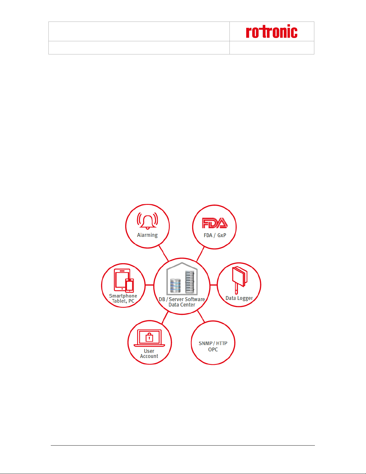
The Rotronic Monitoring System (RMS) is a network comprising various devices and the RMS server software.
The software is the heart of the system. It collects all measured data of the devices and saves it in the database.
The individual devices work as input modules (data loggers) and as output modules (displays, analog outputs,
switched outputs). The user can view the system data at any time on a PC, laptop or smart phone.
Figure 1: Schematic diagram of the RMS with the server software and database at the heart
Page 4
RMS-LOG Wireless / LAN Data Loggers
E-M-RMS-LOG-V1.4.docx
Instruction Manual
© 2018 ROTRONIC AG Bassersdorf Switzerland Page 4 of 35
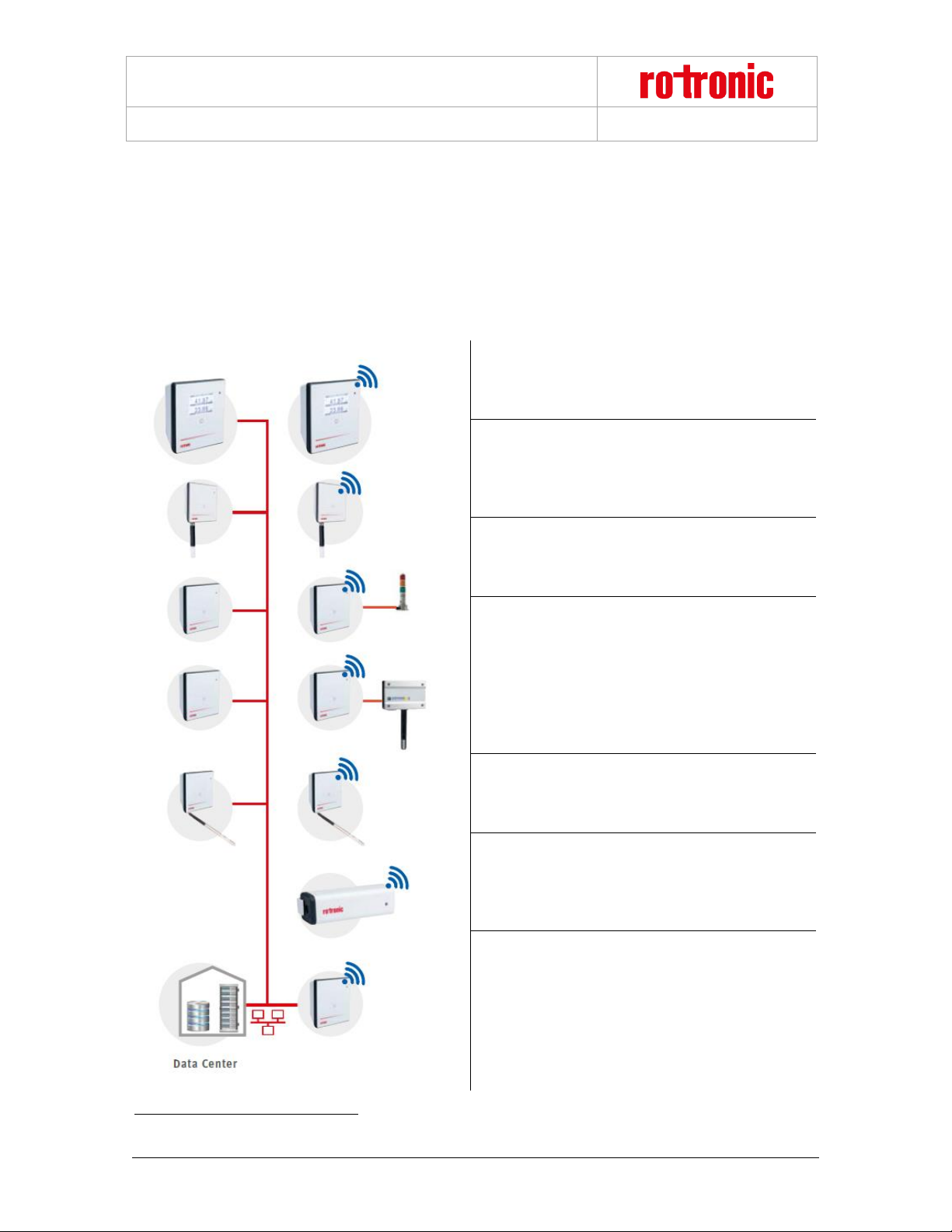
1.2 Device Overview
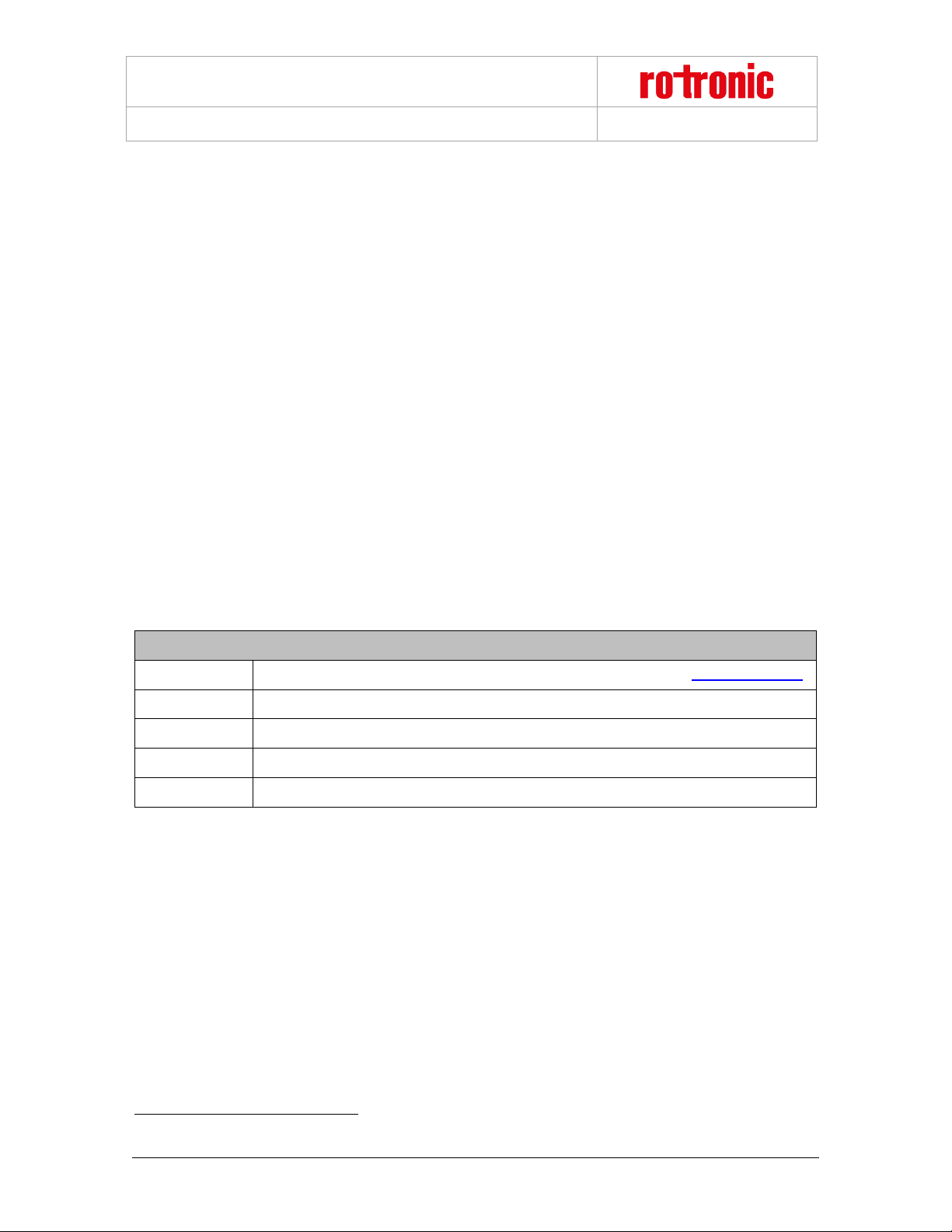
All devices can be configured as wanted as modules of the system. The following table shows all basic types of
the RMS devices. Almost all modules1 have the following options:
Interface: Ethernet / Wireless
Housing: Wall housing / DIN top hat rail housing
Display Module
The display module can show any values from the
RMS network. Humidity, temperature and switch
states can be configured per software.
Standard Logger
Records the measured data of the digital HygroClip
HCD or other RMS probes. Stored in the ring
memory, the data are then sent to the server
software.
Output Module
Provides two analog voltage or current outputs or is
also available as variant with two solid-state relays in
order, for example, to switch alarm lamps.
Input Module
Records voltage or current signals from analog
devices such as particle counters, flow transmitters
or CO2 probes. For example:
HF5 transmitter (humidity & temperature)
AF1 transmitter (air flow)
CO2 transmitter (CO2)
PF4 transmitter (differential pressure)
Temperature Logger
The loggers can be equipped with various
temperature sensors (NTC, Pt100, Pt1000 or Kelement). This offers highest flexibility in use.
Mini Logger
A temperature logger with integrated or remote NTC
sensor. Instead of a temperature sensor, it is also
available with a switch input in order, for example, to
monitor door contacts.
Gateway
The gateway is the connecting element between
Ethernet and wireless network and forwards the data
flow from the loggers to the data centre.
1
Except for the Mini Logger
Page 5

RMS-LOG Wireless / LAN Data Loggers
E-M-RMS-LOG-V1.4.docx
Instruction Manual
© 2018 ROTRONIC AG Bassersdorf Switzerland Page 5 of 35
1.3 RMS Data Logger
Order code: RMS-LOG-L or RMS-LOG-868 or RMS-LOG-915
The data logger carries out measurements in a fixed interval, saves all measured data and sends it to the
database by radio or Ethernet link. Should the connection be lost, the logger stores the data intermediately to
protect data integrity and fills up the data gaps when the connection has been restored. The measurement
parameters depend on the connected probe; two different parameters can be measured at the same time. The
device has a battery so that logging of measured data is also ensured in the event of a failure in the external
power supply.
The data logger provides the following basic functions:
o Logging of the measured values of the connected probe
o Data logging of up to 44,000 pairs of measured values
o Transfer of the recorded data to the RMS software
o Calibration and adjustment of the probe
o Firmware update
1.4 RMS Display
Order code: RMS-D-L
The RMS Display is a freely configurable device. The unit can be placed anywhere, not necessarily next to the
measurement point. The display allows the visualisation of measurement values, conditions and alarms of
devices within the RMS software.
The RMS Display provides the following basic functions:
o Display of up to 4 measuring values and their trends
o Actualisation every 10s
o Display of errors, alarms, warnings and notifications
o Display of the time
The RMS display will show 2 measurement values at a time. Should more than 2 measurement values be
selected, then the display will automatically switch every 5 seconds between the measurement values.
Under each measurement value, the name of the measuring point will be indicated. The parameter will be
shown on the right, next to the measurement value
Various notifications can also be displayed:
o Error: E
o Alarm: A
o Warning: W
o Reminder: R
Page 6
RMS-LOG Wireless / LAN Data Loggers
E-M-RMS-LOG-V1.4.docx
Instruction Manual
© 2018 ROTRONIC AG Bassersdorf Switzerland Page 6 of 35
When an alarm is shown, the display will also turn red and the name of the measuring point will be inverted.
Additionally, the date and time are also shown on the RMS Display, all data is collected from the Web service.
1.5 Power Supply
All input modules (data loggers) have the following three power supply variants:
Two 3.6 V lithium thionyl chloride AA batteries
The power supply of the batteries suffices to carry out measurement and data storage and to operate
the wireless interface. Devices with an Ethernet interface must also have one of the following power
supplies. IMPORTANT: The RMS Display is not battery powered!
24 VDC ±10 % / <100 mA2 via terminals (V+ / V-)
Power over Ethernet (PoE), per standard IEEE 802.3af, Class 1
Note on the batteries:
The AA batteries are lithium thionyl chloride batteries available in the industrial trade. All RMS input modules
are designed for this type of battery. Only batteries of the same type or with identical characteristic values may
be used as replacement batteries.
1.5.1 Type of Battery
Battery Specifications
Article
RMS-BAT( ER14505M, multiple manufacturer, please see for Details www.rotronic.com)
Type
Li-SOCl2
Capacitance
~2200 mAh
Voltage
3.6 V
Dimensions
AA (H: 50.3 mm, D: 14.55 mm)
1.6 Measured Parameters
Depending on the version, the RMS data loggers have different inputs. Devices with interchangeable probes
(E2 connector) detect the measurement parameter of the probe automatically. The following table lists the main
types:
2
Power supply requirements: 24 VDC ±10 % / >4 W nominal / <15W limited power source
Page 7
RMS-LOG Wireless / LAN Data Loggers
E-M-RMS-LOG-V1.4.docx
Instruction Manual
© 2018 ROTRONIC AG Bassersdorf Switzerland Page 7 of 35
Data Loggers for Interchangeable Probes
RMS-LOG-L
Data logger, external probe, LAN
RMS-LOG-868
Data logger, external probe, 868 MHz
RMS-LOG-915
Data logger, external probe, 915 MHz
Gateway
RMS-GW-868
Gateway, LAN to 868 MHz
RMS-GW-915
Gateway, LAN to 915 MHz
Temperature Data Loggers
RMS-LOG-T30-L
Data logger, external probe, LAN, 2 x Pt100
RMS-LOG-T30-868
Data logger, external probe, 868 MHz, 2 x Pt100
Mini data logger Modules
RMS-MADC-xxx-A
Data logger, 1 x analog input, 868 / 915 MHz, 0(4)…20 mA
RMS-MADC-868-V
Data logger, 1 x analog input, 868, 0…10V
RMS-MLOG-B-xxx
Mini data logger, integrated temperature & humidity probe,%rh, °C, 868 / 915 MHz
RMS-MLOG-T-xxx
Mini data logger, integrated temperature probe, °C, 868 / 915 MHz
RMS-MLOG-T10-xxx
Mini data logger, external NTC probe, °C, 868 / 915 MHz, NTC needs to be ordered
separately
RMS-MLOG-LGT-868
Mini data logger, integrated light sensor, 868 MHz
RMS-MDI-868
Mini data logger, 1 x digital input, 868 MHz
Analog Input Modules
RMS-4RTD-L-R
Input Module, 4 x PT100 input, LAN
RMS-8ADC-L-R-V
Input Module, 8 x analog input, 0…10 V, LAN
RMS-8ADC-L-R-A
Input Module, 8 x analog input, 0…20mA, LAN
Digital Input Modules
RMS-DI-L-R
Data logger, 2 x digital input, LAN, DIN Rail
Digital Output Modules
RMS-DO-L-R
Data logger, 2 x digital output, LAN, DIN Rail
Display Modules
RMS-D-L
Display, 4 x Measurement points, LAN
Page 8
RMS-LOG Wireless / LAN Data Loggers
E-M-RMS-LOG-V1.4.docx
Instruction Manual
© 2018 ROTRONIC AG Bassersdorf Switzerland Page 8 of 35
1.7 RTCC (Real Time Clock Calendar)
The device has a real time clock calendar. The time is synchronized continuously when connected to the server.
1.8 Data Logging and Measurement Interval
The values of every measurement are saved in the memory with the time stamp. At a measurement interval of
one minute, it is possible to save data of one month, which corresponds to 44,000 pairs of measured values.
When the ring memory is full, the oldest values are overwritten.
1.9 Indicator and Button
The device has a button and multicolour LED for use and indication of the operating state. The button is used
to start the device or switch it off in battery mode. The LED indicates the device status and whether it was
possible in the current measurement interval to carry out a valid measurement and send the data to the
monitoring system.
LED Status Indicator for LAN Devices
Pairing
Trigger
Action
LED
1s press
Confirms pairing
n x orange, the LED flashes
orange when the pairing
demand is open
Remove pairing
Trigger
Action
LED
8s press
Removes pairing, stops logging
and turns off device
3 x red, the pairing information
stored in the logger is deleted
Device status update
Trigger
Action
LED
1s press
Shows the current status
1 x green, the connection to the
server is good
1 x red, battery low
2 x red, there is no connection
to the server
Automatic (every 5 seconds)
Shows the current status
1 x green, the connection to the
server is good
2 x red, there is no connection
to the server
LED Status Indicator for Wireless Devices
Page 9
RMS-LOG Wireless / LAN Data Loggers
E-M-RMS-LOG-V1.4.docx
Instruction Manual
© 2018 ROTRONIC AG Bassersdorf Switzerland Page 9 of 35
Pairing
Trigger
Action
LED
1s press
Confirms pairing
1 x orange, the LED blinks
orange for each channel
searched
Gateway found
n x orange, the LED flashes
orange when the pairing
demand is open
Confirmed pairing
3 x green
Issue pairing (time out, no data
received)
3 x red
Remove pairing
Trigger
Action
LED
8s press
Removes pairing, stops
logging and turns off device
3 x red, the pairing information
stored in the logger is deleted
Device status update
Trigger
Action
LED
1s press
Shows the current status
Green shows the ISM
connection (see below)
1 x red, battery low
2 x red, there is no connection
to the server
Automatic (every 5 seconds)
Shows the current status
1 x green, the connection to the
server is good
2 x red, there is no connection
to the server
Wireless range
Trigger
Action
LED
1s press
Shows the current wireless
status
4 x green, RSSI >-30dBm
3 x green, RSSI >-60dBm
2 x green, RSSI >-80dBm
1 x green, RSSI <=-80dBm
1.10 Interface
The logger is operated completely via the LAN or wireless interface.
1.11 MODBUS communication protocol
For direct connection to other systems, the device provides a MODBUS TCP server. To following data is
available via MODBUS communication:
Page 10
RMS-LOG Wireless / LAN Data Loggers
E-M-RMS-LOG-V1.4.docx
Instruction Manual
© 2018 ROTRONIC AG Bassersdorf Switzerland Page 10 of 35
Description
Details
Protocol
MODBUS TCP
TCP Port
502
Connection timeout:
When TCP connection is open and for more than 30 seconds no communication is performed, the device
automatically closes the TCP connection. In case of a communication interruption, this prohibits that the socket
is could be blocked.
1.11.1 Function 04- Read Input Register
Device Data
Register
Parameter
Data type
30001
Serial number Unsigned 32 Bit
30002
30003
Serial number oft he
sensors
Unsigned 32 Bit
30004
Float Values
Register
Parameter
Data type
31001
Value 1
Measurement value
sensor 1
Float 32 Bit
31002
31003
Value 2
Measurement value
sensor 2
Float 32 Bit
31004
Integer Values
The measurement values are only available in floating format.
1.11.2 Swap mode
The swap mode defines how a float32 value is represented in MODUBS data structure. The settings must be
done with the RMS-CONFIG software.
Factory settings: WORD-Swap
Example:
Page 11
RMS-LOG Wireless / LAN Data Loggers
E-M-RMS-LOG-V1.4.docx
Instruction Manual
© 2018 ROTRONIC AG Bassersdorf Switzerland Page 11 of 35
Value 1 (Address 31001 / 31002): 45.0 = 0x42340000
Value 2 (Address 31001 / 31002): 1000.0 =
0x447A0000
The following website helps for conversion:
https://www.hschmidt.net/FloatConverter/IEEE754de.html
NoChange (Big Endian)
31001 16948 0x4234
31002 0 0x0000
31003 17530 0x447A
31004 0 0x0000
Word Swap (Mixed Endian)
31001 0 0x0000
31002 16948 0x4234
31003 0 0x0000
31004 17530 0x447A
Byte Swap (Middle Endian)
31001 13378 0x3442
31002 0 0x0000
31003 31300 0x7A44
31004 0 0x0000
Byte and Word Swap (Little Endian)
31001 0 0x0000
31002 13378 0x3442
31003 0 0x0000
31004 31300 0x7A44
Software Compatibility
The logger is designed for use with the RMS server software (local installation or Rotronic Cloud). The data
logger can alternatively also be operated with the RMS configuration software (standalone software).
Page 12

RMS-LOG Wireless / LAN Data Loggers
E-M-RMS-LOG-V1.4.docx
Instruction Manual
© 2018 ROTRONIC AG Bassersdorf Switzerland Page 12 of 35
2 Dimensions
The RMS data logger, the gateway and the display are all integrated in the same wall housing. All dimensions
are shown in Figure 2.
Figure 2: Dimensions of the wall housing
Figure 3: Mounting bracket with dimensions for drill holes
Page 13

RMS-LOG Wireless / LAN Data Loggers
E-M-RMS-LOG-V1.4.docx
Instruction Manual
© 2018 ROTRONIC AG Bassersdorf Switzerland Page 13 of 35
3 Installation
There is a difference between mechanical installation of the wall housing and the DIN top hat rail housing. This
manual only describes installation of the wall housing. Installation of the DIN top hat rail housing requires no
special handling. All terminal markings are identical to those of the wall housing.
The following instructions describe installation of the data logger step by step.
1
Press a blunt object (e.g.
screwdriver in the AC1321
mounting kit) lightly into the
hole opening on the top
side of the housing. The
flap springs open.
2
Press the cover to the back
and take off from the basic
unit.
Page 14

RMS-LOG Wireless / LAN Data Loggers
E-M-RMS-LOG-V1.4.docx
Instruction Manual
© 2018 ROTRONIC AG Bassersdorf Switzerland Page 14 of 35
3
The cover has two
suspension openings and
two additional prepared
fastening possibilities3.
4
Insert the batteries at the
back of the device and
remove the insulation
strips.
Make sure they are
inserted correctly. The
poles are marked on the
battery and in the battery
compartment.
3
Only the mounting points provided should be used for mounting.
Page 15

RMS-LOG Wireless / LAN Data Loggers
E-M-RMS-LOG-V1.4.docx
Instruction Manual
© 2018 ROTRONIC AG Bassersdorf Switzerland Page 15 of 35
5
Only for LAN devices:
Make a round opening in
the large rubber seal (use
the mounting cone in
AC1321), pass the cable
through it and fit the rubber
plug in the cover.
6
Only for LAN devices:
Plug the cable into the
device4. For secure
fastening and to ensure a
reliable data link, make
sure it clicks in audibly.
4
The connected cable may not exceed a length of 30 m at most. Disruptions can occur in operation if a longer
cable is used!
Page 16

RMS-LOG Wireless / LAN Data Loggers
E-M-RMS-LOG-V1.4.docx
Instruction Manual
© 2018 ROTRONIC AG Bassersdorf Switzerland Page 16 of 35
7
If necessary:
Connect the device to a
power supply.
8
The wall bracket is
fastened to the wall with
screws according to the
drilling template. The
screws may only protrude
so far that the device can
click into place properly
when put on to the
fastened cover.56
5
The screws must not be tightened.
6
Only use the screws provided in the package. Screw specifications: M3.5. head strength 2.5 mm, head
diameter 7 mm
Page 17

RMS-LOG Wireless / LAN Data Loggers
E-M-RMS-LOG-V1.4.docx
Instruction Manual
© 2018 ROTRONIC AG Bassersdorf Switzerland Page 17 of 35
9
The housing is put in the
wall bracket and clicked
into place.
10
The device can then be
integrated into the server
software. The procedure is
described in the manual
E-SM-RMS-WEB.
Page 18

RMS-LOG Wireless / LAN Data Loggers
E-M-RMS-LOG-V1.4.docx
Instruction Manual
© 2018 ROTRONIC AG Bassersdorf Switzerland Page 18 of 35
11
Insert the probe and fasten
with the thumb screw.
Page 19

RMS-LOG Wireless / LAN Data Loggers
E-M-RMS-LOG-V1.4.docx
Instruction Manual
© 2018 ROTRONIC AG Bassersdorf Switzerland Page 19 of 35
3.1 Drilling Template Wall Bracket
Figure 4: Drawing of the wall bracket (not to scale)
Page 20

RMS-LOG Wireless / LAN Data Loggers
E-M-RMS-LOG-V1.4.docx
Instruction Manual
© 2018 ROTRONIC AG Bassersdorf Switzerland Page 20 of 35
4 Electrical Connections
Figure 5: Electrical connections of the data logger
Number
Marking
Function
1
V+
Power supply +
2
V-
Power supply -
3
RXTX+
Not used
4
RXTX-
Not used
5 – 10
-
No function
Note:
The power supply must be connected to the right terminals. Otherwise the device could be damaged.
4.1 Battery
The batteries serve to supply the device with power in the event of a failure in the external power supply. The
functionality of the device is restricted in battery mode. The device continues to measure and records all data
in the internal memory. The device cannot communicate via the Ethernet interface, but the wireless interface
works normally.
Lithium batteries of the type AA with 3.6 V are used, per section 1.5.1. Make sure they are inserted correctly.
The poles are marked on the battery and in the battery compartment.
Page 21

RMS-LOG Wireless / LAN Data Loggers
E-M-RMS-LOG-V1.4.docx
Instruction Manual
© 2018 ROTRONIC AG Bassersdorf Switzerland Page 21 of 35
5 Operation
This section describes all manipulations necessary for operation.
5.1 Default Configuration
The devices are configured ex works. All devices with a LAN connection have a standard address for the server
with the RMS server software. The standard server corresponds to the Rotronic Cloud. Devices that need to
send the data to a different server need to be reconfigured.
LAN Devices
TCPIP configuration: The DHCP server must be on, the configuration is obtained automatically.
RMS-WEB URL Host: rms.rotronic.com
RMS-WEB URL Path: /wService/wService3.DEviceService.svc
Wireless Devices
The device does not have a wireless configuration on leaving the factory. It is assigned automatically when
pairing the device in a system.
5.2 Configuration of the LAN Devices with RMS-CONFIG
If you do not want to connect the device to the Rotronic Cloud, the server must be configured in the device.
Connect the device to the local network as described in section 3 . Start the RMS configuration
software.
Search for the device under Device > Search > Network Device. The software finds all RMS devices
in the local network.
Enter the host (server address) and the URL of the software services under Settings.
Finish configuration with "Write".
Page 22

RMS-LOG Wireless / LAN Data Loggers
E-M-RMS-LOG-V1.4.docx
Instruction Manual
© 2018 ROTRONIC AG Bassersdorf Switzerland Page 22 of 35
Once they have been configured with the correct server address, the devices can then be integrated into the
server software. Details are described in the manual E-SM-RMS-WEB.
5.3 General Manipulations
Remove Ethernet Cable
The cable can be released with a blunt round object (e.g. ballpoint pen) and the connector pulled out (see
Figure 6).
Figure 6: Removing the Ethernet cable
Page 23

RMS-LOG Wireless / LAN Data Loggers
E-M-RMS-LOG-V1.4.docx
Instruction Manual
© 2018 ROTRONIC AG Bassersdorf Switzerland Page 23 of 35
5.4 Integration in the RMS-WEB Software
5.4.1 LAN Devices
To integrate the device, port 80 must be enabled in your network and a DHCP server must assign the IP
address to the device. The device must be able to reach the server with the RMS server software or the
Cloud.
The devices can also be given a static IP address if there is no DHCP server available in the network.
Integration of the Data Logger (Pairing) in 6 Steps
1
If you do not want to connect the device to the Rotronic Cloud, the server must be configured in
the device.
Connect the device to the local network and start the RMS configuration software.
Search for the device under Device > Search > Network Device. The software finds all
RMS devices in the local network.
Enter the host (server address) and the URL of the software services under Settings.
Finish configuration with “Write”.
2
Log into the RMS software / Cloud. Select Extras > Setup > Devices > New LAN Device
3
Enter the serial number of the device. The device flashes orange.
Page 24

RMS-LOG Wireless / LAN Data Loggers
E-M-RMS-LOG-V1.4.docx
Instruction Manual
© 2018 ROTRONIC AG Bassersdorf Switzerland Page 24 of 35
4
Press the button on the device briefly. The device stops flashing.
5
Configure the device.
The RMS-D-L:
Page 25

RMS-LOG Wireless / LAN Data Loggers
E-M-RMS-LOG-V1.4.docx
Instruction Manual
© 2018 ROTRONIC AG Bassersdorf Switzerland Page 25 of 35
6
Finish configuration.
You can find details in the instruction manual for the RMS server software: E-SM-RMS-WEB
5.4.2 Wireless Devices
To integrate the device in a RMS-WEB system, pairing mode must be enabled via the software on a gateway
within wireless range. The search for the device is started by pressing a button. If it is possible for the device to
connect with the gateway, this is shown by orange flashing. Pairing is then completed as described in the RMSWEB software.
Integration of the Wireless Data Logger (Pairing) in 5 Steps.
1
Log into the RMS software / Cloud. Select Extras > Setup > Devices > New Wireless Device
2
Select the gateway you want your wireless data logger to be connected to. The selected
gateway then changes to pairing mode and flashes orange.
3
Press the button on the device to confirm. The wireless data logger stops flashing.
Page 26

RMS-LOG Wireless / LAN Data Loggers
E-M-RMS-LOG-V1.4.docx
Instruction Manual
© 2018 ROTRONIC AG Bassersdorf Switzerland Page 26 of 35
4
Configure the device.
5
Finish configuration.
You can find details in the instruction manual for the RMS server software: E-SM-RMS-WEB
5.5 Function Overview
Overview of the main software functions of the device
Page 27

RMS-LOG Wireless / LAN Data Loggers
E-M-RMS-LOG-V1.4.docx
Instruction Manual
© 2018 ROTRONIC AG Bassersdorf Switzerland Page 27 of 35
► Discovery
With Discovery it is possible to find devices in the subnet with
the RMS configuration software irrespective of their IP
configuration and to change their settings.
► IP configuration
The devices can have static or dynamic IP configurations. It is
recommended that you use a dynamic IP configuration
whenever possible.
If fixed IPs are used, the network topology must be considered
exactly.
► RMS Web Server settings
Every device has the server address and software path of the
RMS server software stored in it in order to build up
communication with the RMS server software.
The two parameters can be set with the RMS configuration
software:
Host: Address of the server with the RMS software
Server path: Server path where the server software is
installed.
► Measurement by the connected probe
The device recognizes the connected probe automatically and
requests the latest measured data. The measured data are sent
to the RMS server software at the set interval directly after the
measurement.
► Save measured data
The measured values of every measurement are saved in the
internal ring memory (44,000 pairs of measured values). If the
data cannot be sent to the server software directly, they are kept
in the device and then sent later as soon as the connection to
the server software has been restored.
► Battery mode
If the external power supply (24 VDC / PoE) fails, the device
runs in battery mode. Measurements are still carried out at the
set interval and the data saved in the ring memory (44,000 pairs
of measured values).
►Firmware update
The firmware of the device can be updated directly via the RMS
server software.
Page 28

RMS-LOG Wireless / LAN Data Loggers
E-M-RMS-LOG-V1.4.docx
Instruction Manual
© 2018 ROTRONIC AG Bassersdorf Switzerland Page 28 of 35
6 Maintenance
Even the best technology needs regular maintenance. This chapter describes the most important points.
6.1 Battery Replacement
The batteries (see chapter 1.5.1 for the type of battery) of RMS devices typically last 3 years. The device shows
automatically when the battery needs to be replaced.
LED flashes red
System message in the RMS server software
The following steps are necessary to replace the battery:
Take the device out of the wall bracket
Remove the old battery and insert a new one
The time setting of the data logger is synchronized automatically after the battery replacement.
Important:
The battery life depends on the ambient temperature. Low or high temperatures can lead to a shorter
battery life.
Page 29

RMS-LOG Wireless / LAN Data Loggers
E-M-RMS-LOG-V1.4.docx
Instruction Manual
© 2018 ROTRONIC AG Bassersdorf Switzerland Page 29 of 35
7 Firmware Update
The firmware can be updated with the RMS server software. Firmware updates are available for downloading
on the Rotronic website.
Page 30

RMS-LOG Wireless / LAN Data Loggers
E-M-RMS-LOG-V1.4.docx
Instruction Manual
© 2018 ROTRONIC AG Bassersdorf Switzerland Page 30 of 35
8 Technical Specifications
General
Device type
RMS Data Logger
Measured parameters
Humidity & temperature with HygroClip HCD-S
Differencial pressure with PCD-S
CO2 with CCD-S
IP protection class
IP657
Range of application
-40..70 °C / 0..100 %RH
Storage and transport conditions
-40..30 °C / 0..90 %RH
Data memory
44,000 pairs of measured values
Interfaces
Ethernet (RMS-LOG-L)
Wireless 868 MHz (RMS-LOG-868)
Wireless 915 MHz (RMS-LOG-915)
Protocols
HTTP & MODBUS
Wireless range
20..50 m, indoors 868 MHz
15…25 m, indoors 915 MHz
Transmitting power
14dBm (25mW)
2dBm (1,6mW)
Software compatibility
≥V1.1
≥V1.2.1
General
Device type
RMS Display
IP protection class
IP658
Range of application
-20..30 °C / 0..100 %RH
Storage and transport conditions
-20..30 °C / 0..100 %RH
Interfaces
Ethernet (RMS-D-L)
Protocols
HTTP
Power Supply
Supply voltage
24 VDC ±10 % / <100 mA9
PoE: 802.3af-2003, Class 1
7
IP65 protection is only fulfilled, when rubber plug is used for cabling.
8
IP65 protection is only fulfilled, when rubber plug is used for cabling.
9
Power supply requirements: 24 VDC ±10 % / >4 W / limited power source
Page 31

RMS-LOG Wireless / LAN Data Loggers
E-M-RMS-LOG-V1.4.docx
Instruction Manual
© 2018 ROTRONIC AG Bassersdorf Switzerland Page 31 of 35
Battery (No battery option with the RMS-D-L).
Polarity protection
Yes
Current consumption
<100 mA
Battery life
3 years at 23 °C and interval of 1 minute)
Start Time and Measurement Interval
Start time
LAN logger: 10 s (typical)
Wireless logger: 1 s (typical)
LAN display: <20s
Measurement interval
10 s to 15 min
Refresh rate (RMS-D-L)
10 s
Housing Specifications
Housing material
ABS
Dimensions
105 x 113 x 38 mm
Weight
200 g
Conformity
EMC directives
RMS-LOG-L
EMC Directive: 2014/30/EU
LVD Directive: 2014/35/EU
EN 61326-1:2013 (Industrielle Umgebung) IEC 61326-1:2012 ed2.0 (Industrial Environment)
EN 55011:2016, class B IEC CISPR 11:2015; class B
EN 55032:2016 IEC CISPR 32:2016
EN 61010-1:2010 IEC 61010-1:2010
EN 50581:2012 IEC 50581:2013-02
Performance criterion: www.rotronic.com
Page 32

RMS-LOG Wireless / LAN Data Loggers
E-M-RMS-LOG-V1.4.docx
Instruction Manual
© 2018 ROTRONIC AG Bassersdorf Switzerland Page 32 of 35
EMC directives
RMS-LOG-868
RED-Directive 2014/53/EU
EN 61326-1:2013 IEC 61326-1:2012 ed2.0
EN 301 489-1: V2.1.1
EN 301 489-3: V2.1.0
EN 300220-1: 2013-02 / V2.4.1
EN 300220-2: 2013-02 / V2.4.1
EN 62479: 2010
EN 62368-1: 2014 + AC:2015 + Ber 1:2016-11 IEC 62368-1: 2014 + Cor.:2015
EN 50581:2012 IEC 50581:2013-02
Performance criterion: www.rotronic.com
EMC directives
RMS-D-L
EMC Directive: 2014/30/EU
LVD Directive: 2014/35/EU
EN 61326-1:2012 (Industrielle Umgebung) IEC 61326-1:2013 (Industrial Environment)
EN 55011:2016, class B IEC CISPR 11:2015; class B
EN 55032:2015 IEC CISPR 32:2015
EN 61010-1:2010 IEC 61010-1:2010
EN 50581:2012
Performance criterion: www.rotronic.com
FCC
RMS-LOG-915
FCC 47 CFR part 15 subpart B: Clause 15.107 + Clause 15.109
FCC 47 CFR part 15 subpart C: Clause 15.249 (
ICES-003 Issue 6: Clause 6.1 + Clause 6.2
RSS Issue 5: RSS-102 + RSS-210
Soldering material
Lead free (RoHS Directive 2011/65/EU)
FDA / GAMP
directives
FDA CFR21 Part 11 / GAMP5
Page 33

RMS-LOG Wireless / LAN Data Loggers
E-M-RMS-LOG-V1.4.docx
Instruction Manual
© 2018 ROTRONIC AG Bassersdorf Switzerland Page 33 of 35
9 Accessories
All accessories for the HC2A probe such as extension cables, adapters, calibration material, etc are to be found
in the manual E-M-HC2-Accessories.
9.1 RMS Accessories
Order Code
Description
HCD-S
Standard probe, black, %RH & °C
PCD-S
Standard probe, anthracite, Differential pressure
CCD-S
Standard probe, anthracite, CO2
RMS-GW-868
Gateway, LAN to 868 MHz
AC1321
Mounting kit with Allen key and mounting cone
RMS-NPK
Network planning kit: wireless dongle, RMS mini logger
Page 34

RMS-LOG Wireless / LAN Data Loggers
E-M-RMS-LOG-V1.4.docx
Instruction Manual
© 2018 ROTRONIC AG Bassersdorf Switzerland Page 34 of 35
10 Additional Documents
Document Name
Contents
E-IM-RMS-WEB
Instruction Manual: System Installation
E-SM-RMS-WEB
Instruction Manual: System Startup
E-OM-RMS-WEB
Instruction Manual: System Operation
E-M-RMS-GW-868
Instruction Manual: Gateway
E-M-RMS-MLOG
Instruction Manual: Mini Logger
E-M-RMS-LOG-R
Instruction Manual: Din rail logger
Page 35

RMS-LOG Wireless / LAN Data Loggers
E-M-RMS-LOG-V1.4.docx
Instruction Manual
© 2018 ROTRONIC AG Bassersdorf Switzerland Page 35 of 35
11 Document Version
Version
Date
Notes
V1_0
October 2016
First version
V1_1
November 2016
Update IP protection
Update power supply specifications
MODBUS commands integrated
V1.2
May 2017
1.4 RMS Display: New
1.5 Power suppler: Updated for the RMS Display
1.6 Measured parameters: Updated table
1.9 Indicator and button: Updated table
5.4.1: Configuration RMS-D-L
8 Technical specification: New RMS Display details
10 Additional documentation: New Manual
V1.3
March 2018
1.5.1 Battery specification: Updated table
1.1 Modbus: Updated Read input register 04
8 Technical specification: Updated table
9.1 RMS accessories: Additional accessories
V1.4
April 2018
1.6 Measured parameter: Updated table
8 Technical specification: Updated table
 Loading...