

Page 1
RMS Gateway
© 2016 ROTRONIC AG Bassersdorf Switzerland
Page 2

RMS-GW-868 Gateway
E-M-RMS-GW-868-V1_0.docx
Instruction Manual
Table of Contents
1
Overview ................................................................................................................................................. 3
1.1 RMS System Overview ........................................................................................................................ 3
1.2 Device Overview .................................................................................................................................. 4
1.3 RMS Gateway ...................................................................................................................................... 5
1.4 Power Supply ....................................................................................................................................... 5
1.5 RTCC (Real Time Clock Calendar) ...................................................................................................... 6
1.6 Interval ................................................................................................................................................. 6
1.7 Indicator and Button ............................................................................................................................. 6
1.8 Interface ............................................................................................................................................... 6
1.9 Software Compatibility ......................................................................................................................... 6
2 Dimensions ............................................................................................................................................ 7
3 Installation .............................................................................................................................................. 8
3.1 Drilling Template Wall Bracket ........................................................................................................... 13
4 Electrical Connections ........................................................................................................................ 14
5 Operation .............................................................................................................................................. 15
5.1 Default Configuration ......................................................................................................................... 15
5.2 Configuration with RMS-CONFIG ...................................................................................................... 16
5.3 General Manipulations ....................................................................................................................... 17
5.4 Integration in the RMS-WEB Software ............................................................................................... 18
5.5 Function Overview ............................................................................................................................. 20
6 Firmware Update.................................................................................................................................. 21
7 Technical Specifications ..................................................................................................................... 22
8 Accessories ......................................................................................................................................... 24
9 Additional Documents ......................................................................................................................... 25
10 Document Version ............................................................................................................................... 26
© 2016 ROTRONIC AG Bassersdorf Switzerland Page 2 of 26
Page 3
RMS-GW-868 Gateway
E-M-RMS-GW-868-V1_0.docx
Instruction Manual
Scope:
This manual is valid for the RMS gateways from firmware version V1.x. The low-order digit of the firmware
version stands for minor changes, e.g. correction of errors that do not influence the main functionality of the
device.
1 Overview
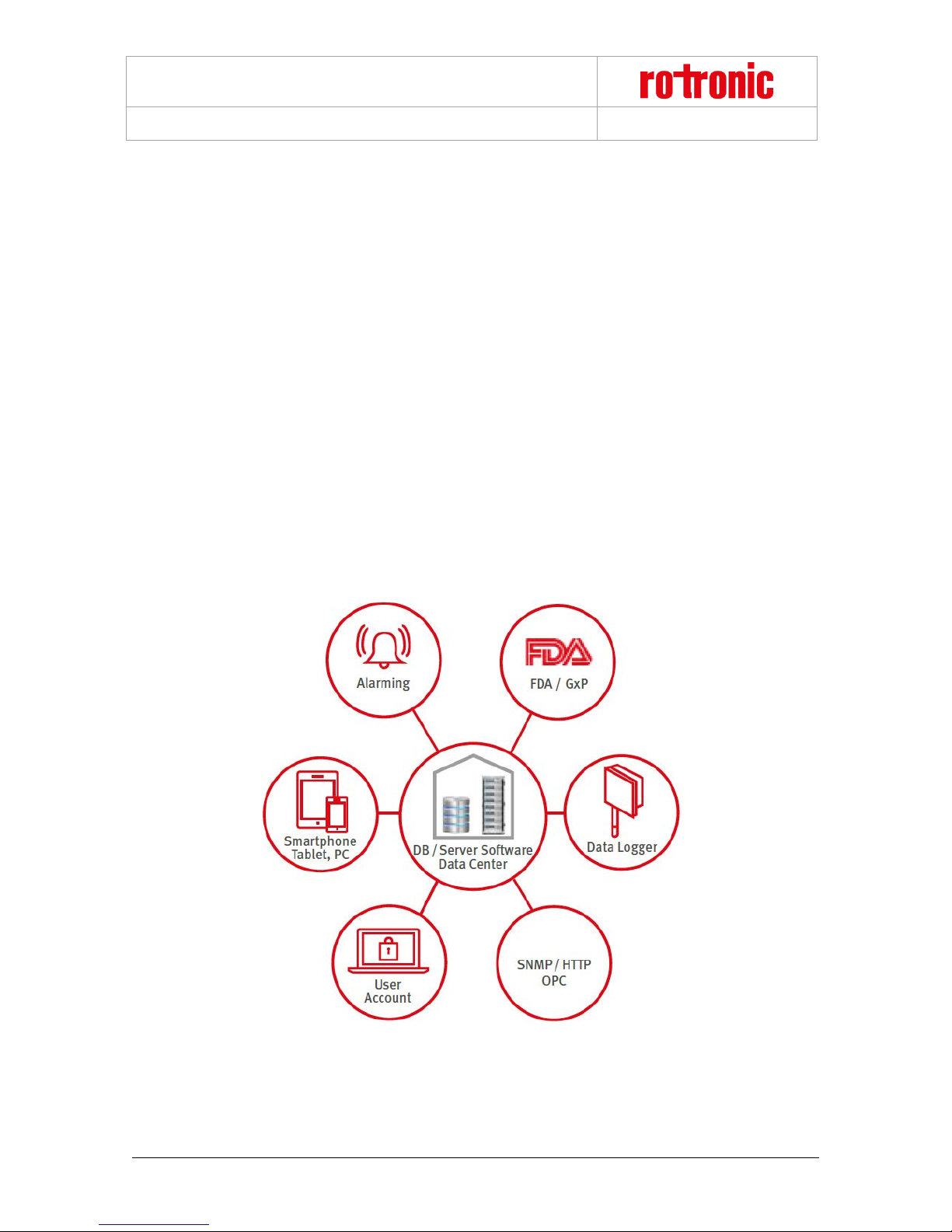
1.1 RMS System Overview
The Rotronic Monitoring System (RMS) is a network comprising various devices and the RMS server software.
The software is the hear t of the system. It collects all measure d data of t he devices an d save s it in the d atabase.
The individual devices work as input modules (data loggers) and as output modules (displays, analog outputs,
switched outputs). The user can view the system data at any time on a PC, laptop or smart phone.
Figure 1: Schematic diagram of the RMS with the server software and database at the heart
© 2016 ROTRONIC AG Bassersdorf Switzerland Page 3 of 26
Page 4
RMS-GW-868 Gateway
Display Module
Standard Logger
Output Module
Input Module
Temperature Logger
Mini Logger
Gateway
E-M-RMS-GW-868-V1_0.docx
Instruction Manual
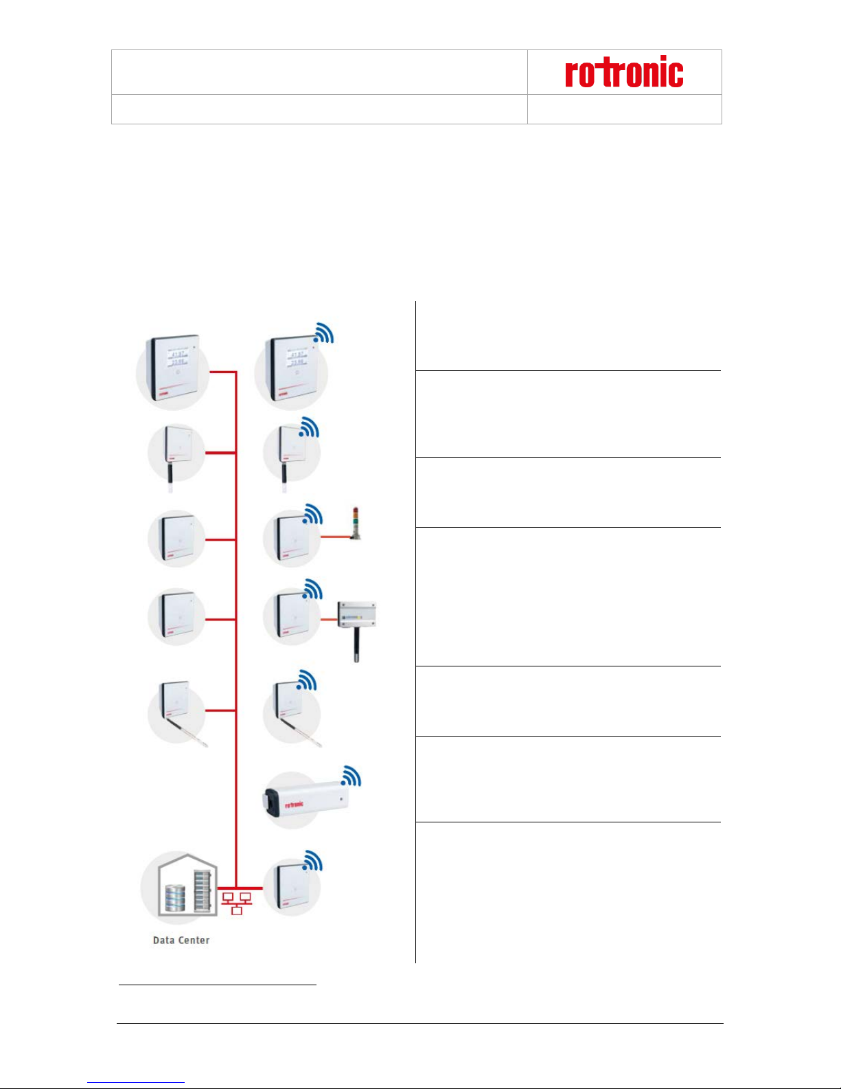
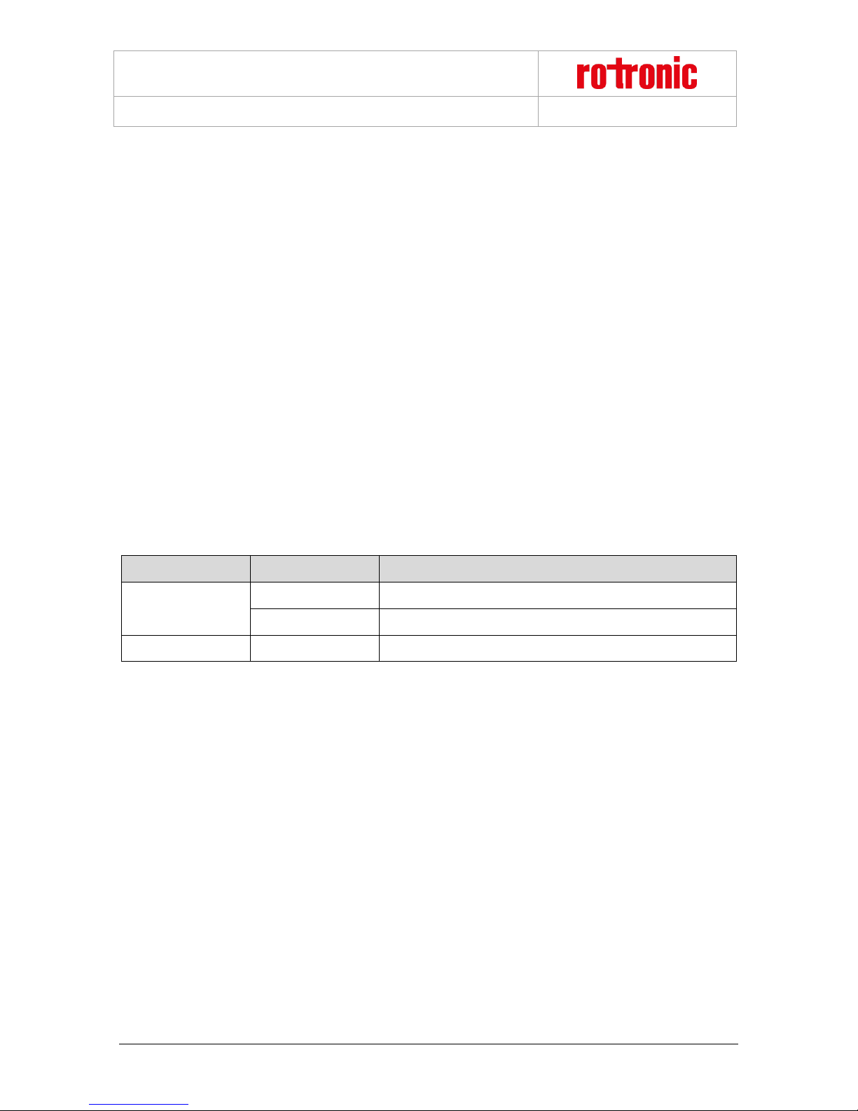
1.2 Device Overview
All devices can be c onfigured as wanted a s mod ule s o f t he system. The follow ing t ab le sho ws all basic types of
the RMS devices. Almost all modules1 have the following options:
• Interface: Ethernet / Wireless
• Housing: Wall housing / DIN top hat rail housing
The display module can show any values from the
RMS network. Humidity, temperature and switch
states can be configured per software.
Records the measured data of the digital HygroClip
HCD or other RMS probes. Stored in the ring
memory, the data are then sent to the server
software.
Provides two analog voltage or current outputs or is
also available as variant with two solid-state relays in
order, for example, to switch alarm lamps.
1
© 2016 ROTRONIC AG Bassersdorf Switzerland Page 4 of 26
Records voltage or current signals from analog
devices such as particle counters, flow transmitters
or CO2 probes. For example:
• HF5 transmitter (humidity & temperature)
• AF1 transmitter (air flow)
• CO2 transmitter (CO2)
• PF4 transmitter (differential pressure)
The loggers can be equipped with various
temperature sensors (NTC, Pt100, Pt1000 or Kelement). This offers the highest flexibility in use.
A temperature logger with integrated or remote NTC
sensor. Instead of a temperature sensor , it is also
available with a switch input in order, for example, to
monitor door contacts.
The gateway is the connecting element between
Ethernet and wireless network and forwards the data
flow from the loggers to the data centre.
Except for the Mini Logger
Page 5

RMS-GW-868 Gateway
E-M-RMS-GW-868-V1_0.docx
Instruction Manual
1.3 RMS Gateway
The gateway is the interface between the wire data logger and the web software. The gateway can manage up
to 60 data loggers simultaneou sly, collect ing all w ireless logge r data and passing the m on to t he server softw are.
When several gateways are us ed in t he sam e netw or k, they a re configured redundantly. If o ne gateway should
fail, the data are automatically sent to the server software via another gateway.
The gateway provides the following basic functions:
o Collection of all measured data from the wireless data loggers
o Transfer of the recorded data to the RMS software
o Firmware update
1.4 Power Supply
The gateway has the following two power supply variants:
• 24 V (< 50 mA) via terminals (V+ / V-)
• Power over Ethernet (PoE), per standard IEEE 802.3af, Class 1
© 2016 ROTRONIC AG Bassersdorf Switzerland Page 5 of 26
Page 6
RMS-GW-868 Gateway
Status
LED Function
Meaning
Flashes green
Status OK
Flashes red
2 times: no connection to server
Not connected
Flashes orange
Device waiting for integration into the software
E-M-RMS-GW-868-V1_0.docx
Instruction Manual
1.5 RTCC (Real Time Clock Calendar)
The device has a rea l time cloc k calendar. The ti me is sync hronized continuous ly when co nnected to the ser ver.
1.6 Interval
The interval for data transfer is exactly the same as that of the connected data loggers. At every interval the
gateway receives the latest measured values from the data loggers and sends them to the server software.
1.7 Indicator and Button
The device has a button and multicolour LED for use and indication of the operating state. The button is used
to start the device or switch it off in battery mode. The LED indicates the device status and whether it was
possible in the current measurement interval to carry out a valid measurement and send the data to the
monitoring system.
LED Status Indicator for LAN Devices
Connected
1.8 Interface
The gateway is operated completely via the LAN interface and does not have an additional service connector.
1.9 Software Compatibility
The gateway is designed for use with the RMS server software (local installation or Rotronic Cloud). The
gateway can alternatively also be operated with the RMS configuration software (standalone software).
© 2016 ROTRONIC AG Bassersdorf Switzerland Page 6 of 26
Page 7

RMS-GW-868 Gateway
E-M-RMS-GW-868-V1_0.docx
Instruction Manual
2 Dimensions
The data logger and the gateway of the RMS are all integrated in the same wall housing. All dimensions are
shown in Figure 2.
Figure 2: Dimensions of the wall housing
Figure 3: Mounting bracket with dimensions for drill holes
© 2016 ROTRONIC AG Bassersdorf Switzerland Page 7 of 26
Page 8
RMS-GW-868 Gateway
E-M-RMS-GW-868-V1_0.docx
Instruction Manual
3 Installation
There is a difference between mechanical installation of the wall housing and the DIN top hat rail housing. This
manual only describes installation of the wall housing. Installation of the DIN top hat rail housing requires no
special handling. All terminal markings are identical to those of the wall housing.
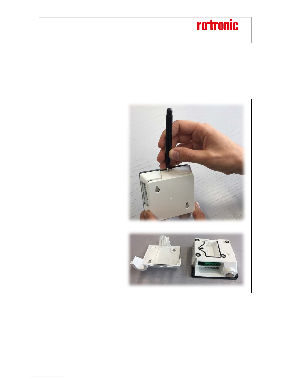
The following instructions describe installation of the data logger step by step.
Press a blunt object (e.g.
screwdriver in the AC1321
1
mounting kit) lightly into the
hole opening on the top
side of the housing. The
flap springs open.
Press the cover to the back
2
© 2016 ROTRONIC AG Bassersdorf Switzerland Page 8 of 26
and take off from the basic
unit.
Page 9

RMS-GW-868 Gateway
E-M-RMS-GW-868-V1_0.docx
The cover has two
3
suspension openings and
two additional prepared
fastening possibilities
Instruction Manual
2
.
4
Make a round opening in
the large rubber seal (use
the mounting cone in
AC1321), pass the cable
through it and fit the rubber
plug in the cover.
2
Only the mounting points provided should be use d for mounting.
© 2016 ROTRONIC AG Bassersdorf Switzerland Page 9 of 26
Page 10

RMS-GW-868 Gateway
E-M-RMS-GW-868-V1_0.docx
Plug the cable into the
device3. For secure
5
fastening and to ensure a
reliable data link, make
sure it clicks in audibly.
Instruction Manual
If necessary:
6
3
The connected cable may not exceed a length of 30 m at most. Disruptions can oc cur in operation if a longer
cable is used!
Connect the device to a
power supply.
© 2016 ROTRONIC AG Bassersdorf Switzerland Page 10 of 26
Page 11

RMS-GW-868 Gateway
E-M-RMS-GW-868-V1_0.docx
The wall bracket is
fastened to the wall with
screws according to the
drilling template. The
7
screws may only protrude
so far that the device can
click into place properly
when put on to the
fastened cover.
Instruction Manual
© 2016 ROTRONIC AG Bassersdorf Switzerland Page 11 of 26
Page 12

RMS-GW-868 Gateway
E-M-RMS-GW-868-V1_0.docx
The housing is put in the
8
wall bracket and clicked
into place.
Instruction Manual
The device can then be
integrated into the server
9
software. The procedure is
described in the manual
E-SM-RMS-WEB.
© 2016 ROTRONIC AG Bassersdorf Switzerland Page 12 of 26
Page 13

RMS-GW-868 Gateway
E-M-RMS-GW-868-V1_0.docx
3.1 Drilling Template Wall Bracket
Instruction Manual
Figure 4: Drawing of the wall bracket (not to scale)
© 2016 ROTRONIC AG Bassersdorf Switzerland Page 13 of 26
Page 14
RMS-GW-868 Gateway
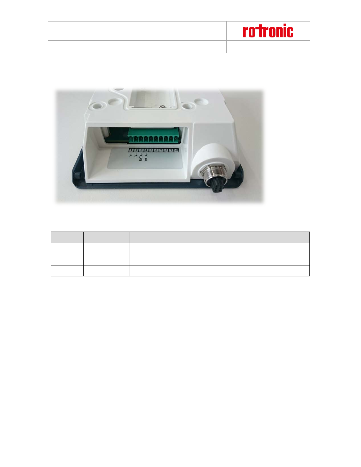
Number
Marking
Function
1
V+
Power supply +
2
V-
Power supply -
3 – 10
-
No function
E-M-RMS-GW-868-V1_0.docx
4 Electrical Connecti ons
Figure 5: Electrical connections of the data logger
Instruction Manual
Note:
The power supply must be connected to the right terminals. Otherwise the device could be damaged.
© 2016 ROTRONIC AG Bassersdorf Switzerland Page 14 of 26
Page 15

RMS-GW-868 Gateway
E-M-RMS-GW-868-V1_0.docx
Instruction Manual
5 Operation
This section describes all manipulations necessary for operation.
5.1 Default Configuration
The devices are configured ex works. All devices have a standard address for the server with the RMS server
software. The standard server corresponds to the Rotronic Cloud. Devices that need to send the data to a
different server need to be reconfigured.
TCPIP configuration: The DHCP server must be on, the configuration is obtained automatically.
RMS-WEB Server URL: http://rms.rotronic.com/wService/wService3.DeviceService.svc
© 2016 ROTRONIC AG Bassersdorf Switzerland Page 15 of 26
Page 16

RMS-GW-868 Gateway
E-M-RMS-GW-868-V1_0.docx
Instruction Manual
5.2 Configuration with RMS-CONFIG
If you do not want to connect the device to the Rotronic Cloud, the server must be configured in the device.
• Connect the device to the local network as described in section 3 . Start the RMS configuration
software.
• Search for the device under Device > Search > Network Device. The software finds all RMS devices
in the local network.
• Enter the host (server address) and the URL of the software services under Settings.
• Finish configuration with "Write".
Once they have been configured with the correct server address, the devices can then be integrated into the
server software. Details are described in the manual E-SM-RMS-WEB.
© 2016 ROTRONIC AG Bassersdorf Switzerland Page 16 of 26
Page 17

RMS-GW-868 Gateway
E-M-RMS-GW-868-V1_0.docx
Instruction Manual
5.3 General Manipulations
Remove Ethernet Cable
The cable can be released with a blunt round object (e.g. ballpoint pen) and the connector pulled out (see
Figure 6).
Figure 6: Removing the Ethernet cable
© 2016 ROTRONIC AG Bassersdorf Switzerland Page 17 of 26
Page 18

RMS-GW-868 Gateway
If you do not want to connect the device to the Rotronic Cloud, the server must be configured in
Log into the RMS software / Cloud. Select Extras > Setup > Devices > New LAN Device
Enter the serial number of the device. The device flashes orange.
Press the button on the device briefly. The device stops flashing.
E-M-RMS-GW-868-V1_0.docx
Instruction Manual
5.4 Integration in the RMS-WEB Software
To integrate the device, port 80 must be enabled in your network and a DHCP server must assign the IP
address to the device. The device must be able to reach the server with the RMS server software or the
Cloud.
The devices can also be given a static IP address if there is no DHCP server available in the network.
Integration of the Gateway (Pairing) in 6 Steps
the device.
• Connect the device to the local network and start the RMS configuration software.
1
• Search for the device under Device > Search > Network Device. The software finds all
RMS devices in the local network.
• Enter the host (server address) and the URL of the software services under Settings.
• Finish configuration with “Write”.
2
3
4
© 2016 ROTRONIC AG Bassersdorf Switzerland Page 18 of 26
Page 19

RMS-GW-868 Gateway
Configure the device.
Finish configuration.
E-M-RMS-GW-868-V1_0.docx
5
Instruction Manual
6
You can find details in the instruction manual for the RMS server software: E-SM-RMS-WEB
© 2016 ROTRONIC AG Bassersdorf Switzerland Page 19 of 26
Page 20

RMS-GW-868 Gateway
► Discovery
With Discovery it is possible to find devices in the subnet with
► IP configuration
The devices can have static or dynamic IP configurations. It
► RMS Web Server settings
Every device has the server address and software path of the
►Firmware update
The firmware of the device can be updated directly via the
E-M-RMS-GW-868-V1_0.docx
5.5 Function Overview
Overview of the main software functions of the device.
the RMS configuration software irrespective of their IP
configuration and to change their settings.
is recommended that you use a dynamic IP configuration
whenever possible.
If fixed IPs are used, the network topology must be
considered exactly.
RMS server software stored in it in order to build up
communication with the RMS server software.
The two parameters can be set with the RMS configuration
software:
• Host: Address of the server with the RMS software.
• Server path: Server path where the server software is
installed.
Instruction Manual
RMS server software.
© 2016 ROTRONIC AG Bassersdorf Switzerland Page 20 of 26
Page 21

RMS-GW-868 Gateway
E-M-RMS-GW-868-V1_0.docx
Instruction Manual
6 Firmware Update
The firmware can be updated with the RMS server software. Firmware updates are available for downloading
on the Rotronic website.
© 2016 ROTRONIC AG Bassersdorf Switzerland Page 21 of 26
Page 22

RMS-GW-868 Gateway
General
Device type
RMS Gateway
IP protection class
IP65
Range of application
-40..85 °C / 0..100 %RH
Storage and transport conditions
-40..30 °C / 0..90 %RH
Interfaces
Ethernet / Wireless 868 MHz
Protocols
HTTP
Wireless range
20..50 m, indoors
Power Supply
Supply voltage
24 VDC / PoE: 802.3af-2003, Class 1
Polarity protection
Yes
Current consumption
<50 mA
Start Time and Measurement Interval
Start time
10 s (typical)
Measurement interval
10 s to 15 min
Housing Specifications
Housing material
ABS
Dimensions
105 x 113 x 38 mm
Weight
200 g
E-M-RMS-GW-868-V1_0.docx
7 Technical Specifications
Instruction Manual
© 2016 ROTRONIC AG Bassersdorf Switzerland Page 22 of 26
Page 23

RMS-GW-868 Gateway
Conformity
EMC Directive: 2014/30/EU
Soldering material
Lead free (RoHS Directive 2011/65/EU)
FDA / GAMP directives
FDA CFR21 Part 11 / GAMP5
E-M-RMS-GW-868-V1_0.docx
EMC directives
Instruction Manual
EN 61000-6-1: 2007
EN 61000-6-2: 2005
EN 61000-6-3: 2007+A1:2011+AC:2012
EN 61000-6-4: 2007+A1:2011
EN 61326-1: 2013
Performance criterion: www.rotronic.com
© 2016 ROTRONIC AG Bassersdorf Switzerland Page 23 of 26
Page 24

RMS-GW-868 Gateway
Order Code
Description
E-M-RMS-GW-868-V1_0.docx
8 Accessories
AC1321
RMS-NPK
Instruction Manual
Mounting kit with Allen key and mounting cone
Network planning kit: wireless dongle, RMS mini logger
© 2016 ROTRONIC AG Bassersdorf Switzerland Page 24 of 26
Page 25
RMS-GW-868 Gateway
Document Name
Contents
E-M-RMS-GW-868-V1_0.docx
9 Additional Documents
E-IM-RMS-WEB
E-SM-RMS-WEB
E-OM-RMS-WEB
E-M-RMS-LOG
E-M-RMS-MLOG
Instruction Manual: System Installation
Instruction Manual: System Startup
Instruction Manual: System Operation
Instruction Manual: Data Logger
Instruction Manual: Mini Logger
Instruction Manual
© 2016 ROTRONIC AG Bassersdorf Switzerland Page 25 of 26
Page 26
RMS-GW-868 Gateway
Version
Date
Notes
V1_0
October 2016
First version
E-M-RMS-GW-868-V1_0.docx
10 Document Version
Instruction Manual
© 2016 ROTRONIC AG Bassersdorf Switzerland Page 26 of 26
 Loading...