

Page 1
E-M-PF4-V1_00
Document Code Unit
PF4 Differential Pressure Transmitter:
Rotronic AG
Bassersdorf, Switzerland
Instruction Manual
Instruction Manual
Document Title
Page
1 of 54
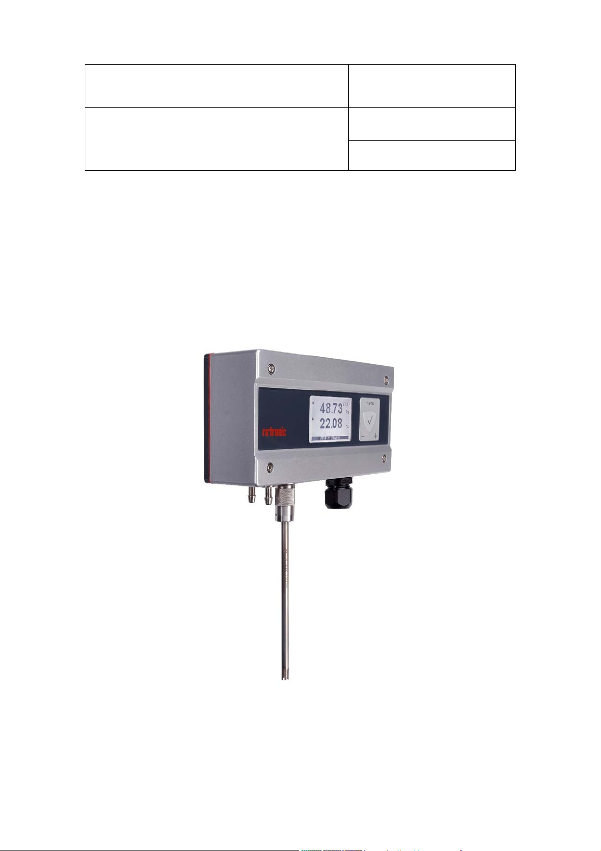
PF4
Differential Pressurep and Temperature Transmitter
Instruction Manual
Document Type
© 2014; Rotronic AG E-M-PF4-V1_00
Page 2

E-M-PF4-V1_00
Document Code Unit
PF4 Differential Pressure Transmitter:
Instruction Manual
Document Title
Contents
Rotronic AG
Bassersdorf, Switzerland
Instruction Manual
Document Type
Page
2 of 54
Contents ............................................................................................................................................................ 2
1 Overview ........................................................ .............................................................. ........................ 4
2 Dimensions .......................................................................................................................................... 5
3 General Description ............................................................................................................................ 6
3.1 Power Supply ................................................................................................................................... 6
3.2 Differential Pressure Measurement .................................................................................................. 7
3.3 Pt100 Connection ........................................................................................................................... 11
3.4 HC2 Connection ............................................................................................................................. 11
3.5 Analog Outputs ............................................................................................................................... 12
3.6 Relay .............................................................................................................................................. 14
3.7 Service Interface ............................................................................................................................. 14
3.8 Display and Keys ............................................................................................................................ 15
3.9 HW4 Software Compatibility ........................................................................................................... 16
4 Mechanical Installation ..................................................................................................................... 17
4.1 General ........................................................................................................................................... 17
4.2 Housing .......................................................................................................................................... 17
4.3 Mounting ......................................................................................................................................... 18
4.4 Differential Pressure Connection .................................................................................................... 18
4.5 HC2 / Analog Connection ............................................................................................................... 19
4.6 Pt100 Connection ........................................................................................................................... 21
5 Electrical Installation ........................................................................................................................ 22
5.2 Wiring ............................................................................................................................................. 24
6 Operation ................................................ ........................................................... ................................ 26
6.1 Differential Pressure ....................................................................................................................... 26
6.2 Analog Outputs ............................................................................................................................... 28
6.3 Ethernet Connection ....................................................................................................................... 28
6.4 Analog Input ................................................................................................................................... 29
6.5 Display and Keys ............................................................................................................................ 33
6.6 Relay .............................................................................................................................................. 42
7 Maintenance .................................................. ................................................................. ................... 43
7.1 Service Cable ................................................................................................................................. 43
7.2 Service Port .................................................................................................................................... 43
© 2014; Rotronic AG E-M-PF4-V1_00
Page 3

E-M-PF4-V1_00
Document Code Unit
PF4 Differential Pressure Transmitter:
Instruction Manual
Document Title
Rotronic AG
Bassersdorf, Switzerland
Instruction Manual
Document Type
Page
3 of 54
7.3 Device Calibration and Adjustment Procedure ............................................................................... 44
7.4 Validation of Analog Output Signals ............................................................................................... 48
8 Firmware Update ............................................................................................................................... 48
9 Technical Data ................................................................................................................................... 49
10 Accessories ....................................................................................................................................... 53
10.1 Service Cable ................................................................................................................................. 53
10.2 Pressure Tubes .............................................................................................................................. 53
10.1 Mounting Elements ......................................................................................................................... 53
11 Additional Documents ...................................................................................................................... 54
12 Document Versions ........................................................................................................................... 54
© 2014; Rotronic AG E-M-PF4-V1_00
Page 4

E-M-PF4-V1_00
Document Code Unit
PF4 Differential Pressure Transmitter:
Instruction Manual
Document Title
Rotronic AG
Bassersdorf, Switzerland
Instruction Manual
Document Type
Page
4 of 54
Scope:
This manual is valid for the PF4 transmitter series with firmware version V3.x. The low-order digit of the firmware
version stands for minor changes, e.g. correction of errors that do not influence the main functionality of the
device.
1 Overview
The PF4 is a high-precision differential pressure transmitter. The integrated measurement technology is able to
detect very small differential pressures. The measurement results can be shown on the built-in display and
exported via the analog outputs. Optional connection of a HygroClip2 probe, Pt100 sensor or analog input signal
is possible. The isolated change-over switch of a relay can be controlled with configurable alarms.
Main features of the PF4 transmitter:
High-precision measurement and long-term stability
Fast response time and low hysteresis
Freely configurable analog signals
Isolated integral relay switch contact
Large overload range
Optional HygroClip2 connection for humidity, temperature or analog signals
Selectable units
High immunity to dust and humidity in the environment
New firmware updates will fix newly discovered issues and add new features. The user is encouraged to stay
up to date with the newest firmware.
© 2014; Rotronic AG E-M-PF4-V1_00
Page 5
E-M-PF4-V1_00
Document Code Unit
PF4 Differential Pressure Transmitter:
Instruction Manual
Document Title
Rotronic AG
Bassersdorf, Switzerland
Instruction Manual
Document Type
Page
5 of 54
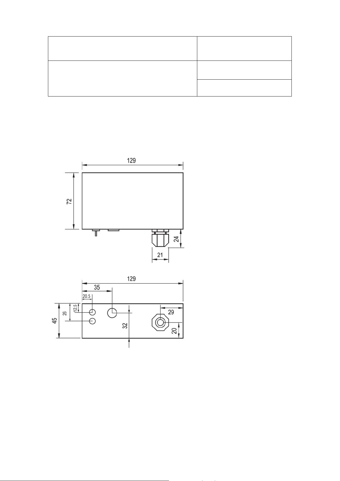
2 Dimensions
The PF4 comes as wall-mounted unit in a ROTRONIC housing. The following drawings show the relevant overall
dimensions in mm.
Figure 1: Important overall dimensions of the PF4
© 2014; Rotronic AG E-M-PF4-V1_00
Page 6

E-M-PF4-V1_00
Document Code Unit
PF4 Differential Pressure Transmitter:
Instruction Manual
Document Title
Rotronic AG
Bassersdorf, Switzerland
Instruction Manual
Document Type
Page
6 of 54
3 General Description
3.1 Power Supply
The PF4 is only available as three-wire version without galvanic isolation. For configuration purposes, the device
can also be supplied with power via the service interface (Mini-USB port inside housing). During configuration
with the service interface there is insufficient power to run the differential pressure sensor to its most accurate
performance levels. The USB service connector should be used only for configuration purposes.
3.1.1 Power Supply / Current Consumption
Power supply specifications for the PF4:
Operating Voltage Current Consumption
15…40 VDC <70 mA / <150 mA (with Ethernet interface)
14…28 VAC – 50/60 Hz <70 mA / <450 mA (with Ethernet interface)
© 2014; Rotronic AG E-M-PF4-V1_00
Page 7
E-M-PF4-V1_00
Document Code Unit
PF4 Differential Pressure Transmitter:
Instruction Manual
Document Title
Rotronic AG
Bassersdorf, Switzerland
Instruction Manual
Document Type
Page
7 of 54
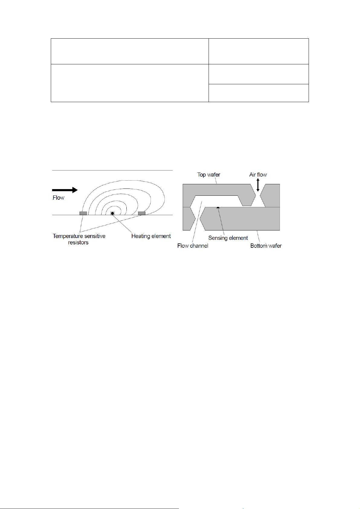
3.2 Differential Pressure Measurement
The differential pressure measurement is based on the principle of thermal mass flow. A flow limiter in a tube
generates a differential pressure. A very small quantity of gas diverted by a bypass before and after the limiter
(max. 180 µl/min) is passed over a differential pressure sensor (∆p sensor) and then returned to the main flow.
Figure 2 on the left shows the principle of this mass flow measurement.
Figure 2:
Principle of the mass flow measurement (left) and cross-section of MEMS differential pressure sensor (right)
The ∆p sensor contains a heating element and a temperature sensor each before and after the heating element.
Due to the differential-pressure dependent flow velocity in the flow passage of the ∆p sensor, the downstream
temperature sensor heats up more or less than the upstream temperature sensor. In this way it is possible to
obtain an output voltage from the ∆p sensor as potential difference between the temperature sensor output
signals that is, following careful linearization, strictly proportional to the volume flow.
The sensor used in the PF4 series is based on a 2x2 mm silicon chip (Figure 2, right). This enables production
of an extremely small and exactly reproducible flow passage with a very high pneumatic resistance, resulting in
extremely small sensor flow rates (max. 180 µl/min) and practically independent of the bypass tube lengths and
dust and moisture loads in the gas stream.
Conclusion: The high measuring sensitivity, accuracy and long-term stability of the ROTRONIC PF4 series
make it the ideal choice for monitoring volume flows and pressures in energy-efficient and economical ventilation
and air conditioning systems.
© 2014; Rotronic AG E-M-PF4-V1_00
Page 8
E-M-PF4-V1_00
Document Code Unit
PF4 Differential Pressure Transmitter:
Instruction Manual
Document Title
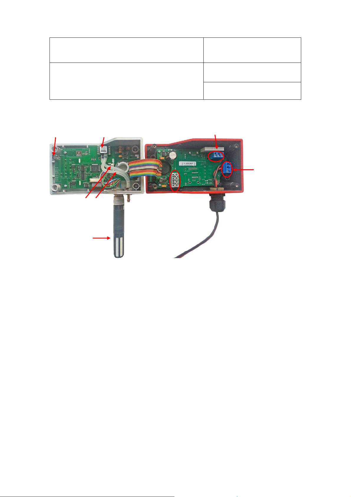
Inside View:
Mini-USB
service connector
Differential pressure
sensor
Terminals K3 for
isolated relay contacts
Rotronic AG
Bassersdorf, Switzerland
Instruction Manual
Document Type
Page
8 of 54
Terminals K2 for power
supply
Differential pressure
tubes
HC2 sensor for
temperature and
relative humidity
Terminals K4 for analog
temp. and differential
Figure 3: Inside view with description of the main components of the PF4
3.2.1 Differential Pressure Measurement Ranges
The following sensor measurement ranges are available:
-25...+25 Pa
-50…+50 Pa
-100…+100 Pa
-250…+250 Pa
-500…+500 Pa
Differential pressures outside the specified ranges are shown, but the measurement results are not reliable.
© 2014; Rotronic AG E-M-PF4-V1_00
Page 9

E-M-PF4-V1_00
Document Code Unit
Rotronic AG
Bassersdorf, Switzerland
PF4 Differential Pressure Transmitter:
Instruction Manual
Document Title
Page
3.2.2 Unit Systems
The following unit systems are available:
Unit Unit Symbol Remarks
Pascal Pa 1 Pa = 1 N/m²
Inch water column inH2O 1 inH2O (4 °C) = 249.089 Pa
Milli-pound-force per square
inch
Millibar mbar 1 mbar = 0.001 bar = 100 Pa
mm mercury column mmHg 1 mmHg (0 °C) = 133.322 Pa
mm water column mmH2O 1 mmH2O (4 °C) = 9.80665 Pa
Torr Torr 1 Torr = 133.322 Pa
Gram per square centimeter g/cm2 1 g/cm2 = 98.0665 Pa
mpsi 1 mpsi = 0.001 psi = 6.89476 Pa
Instruction Manual
Document Type
9 of 54
© 2014; Rotronic AG E-M-PF4-V1_00
Page 10

E-M-PF4-V1_00
Document Code Unit
PF4 Differential Pressure Transmitter:
Instruction Manual
Document Title
Rotronic AG
Bassersdorf, Switzerland
Instruction Manual
Document Type
Page
10 of 54
3.2.3 Filters
The curve of the differential pressure measured values can be smoothened with the help of a low-pass filter
with selectable time constant. There are 13 smoothing filter stages available. Practice has shown stages 0...7
meet most application requirements.
Filter Stage
0 0 s 0 s No filtering
1 0.4 s 1.8 s Weak filtering
2 0.9 s 4.3 s …
3 1.9 s 9.3 s …
Time Constant 63 Time Constant 99
Description
4 3.9 s 19.3 s …
5 7.8 s 39.2 s …
6 15.8 s 78.9 s …
7 32.0 s 2.7 min. …
8 1.0 min. 5.3 min. Strong filtering
9 2.1 min. 10.6 min. …
10 4.2 min. 21.2 min. …
11 8.5 min. 42.4 min. …
12 17.0 min. 1.4 h …
13 33.9 min. 2.8 h Extremely strong filtering
3.2.4 Simulator Value
When the simulator value has been activated, a defined simulator value is used instead of the current measured
value.
© 2014; Rotronic AG E-M-PF4-V1_00
Page 11

E-M-PF4-V1_00
Document Code Unit
PF4 Differential Pressure Transmitter:
Instruction Manual
Document Title
Rotronic AG
Bassersdorf, Switzerland
Instruction Manual
Document Type
Page
11 of 54
3.3 Pt100 Connection
A Pt100 temperature sensor can optionally be connected to the four-pin connector (Binder series 711). The
possible measurement range depends on the Pt100 sensor and is max. -100...200 °C.
3.3.1 Unit Systems
The following unit systems are available for temperature measurement:
°C
°F
3.3.2 Simulator Value
When the simulator value has been activated, a defined simulator value is used instead of the current measured
value.
3.4 HC2 Connection
The PF4 optionally comes with a HC2 connection socket. It can be used for all HC2 probes in the ROTRONIC
portfolio. Alternatively, one pin of the socket can be used as analog current or voltage input. It must be
established on ordering the device whether the pin can evaluate current or voltage signals; it cannot be
reconfigured to do so later on (see chapter 6.4 ).
3.4.1 Unit Systems
The following unit systems are available for the HC2 connection:
%RH
°C / °F
mV / mA
© 2014; Rotronic AG E-M-PF4-V1_00
Page 12

E-M-PF4-V1_00
Document Code Unit
PF4 Differential Pressure Transmitter:
Instruction Manual
Document Title
Rotronic AG
Bassersdorf, Switzerland
Instruction Manual
Document Type
Page
12 of 54
3.4.2 Simulator Value
When the simulation value has been activated, a defined simulator value is used instead of the current measured
value.
3.5 Analog Outputs
The ROTRONIC HW4 software enables free configuration and scaling of the analog outputs. The measured
values (differential pressure, humidity, temperature, calculation value) can be assigned at will to any analog
output (Out1, Out2) and the required range can also be scaled freely.
The following output ranges are available:
Type Range
Voltage
Current
The different variants of the analog output each have a minimal offset:
Signal Type Maximum Offset at Start of Range
0...1 V 3 mV
0...5 V 50 mV
0...10 V 90 mV
0...20 mA 4 µA
4...20 mA No offset
0…1 V
0…5 V
0…10 V
0…20 mA
4…20 mA
© 2014; Rotronic AG E-M-PF4-V1_00
Page 13

E-M-PF4-V1_00
A
Document Code Unit
PF4 Differential Pressure Transmitter:
Instruction Manual
Document Title
Rotronic AG
Bassersdorf, Switzerland
Instruction Manual
Document Type
Page
13 of 54
3.5.1 Scale
The scale can be changed at will with the ROTRONIC HW4 software in a range from -9,999 to +99,999. The
limits of the sensor must, however, be observed (see chapter 3.2 /3.3 / 3.4 ).
The devices have one of the following optional default settings on delivery:
Differential Pressure Humidity Temperature
0…+10 Pa
0…+25 Pa
0…+50 Pa
0…+100 Pa
0…+250 Pa
0…+500 Pa
-25…+25 Pa
-50…+50 Pa
-100…+100 Pa
-250…+250 Pa
-500…+500 Pa
0…100 %RH
0…50 °C
0…70 °C
+10…40 °C
0…+100 °F
0…+200 °F
nalog Input
0…3.2 V
0…25 mA
© 2014; Rotronic AG E-M-PF4-V1_00
Page 14

E-M-PF4-V1_00
Document Code Unit
PF4 Differential Pressure Transmitter:
Instruction Manual
Document Title
Rotronic AG
Bassersdorf, Switzerland
Instruction Manual
Document Type
Page
14 of 54
3.6 Relay
The PF4 provides a freely configurable internal isolated relay contact.
Normally closed (NC)
Common (COM)
Normally open (NO)
The relay can be controlled by freely configurable alarms. The following can also be set:
Time delay
The relay is only switched on when an alarm endures for a certain minimum time.
Switch off when alarm finished
The relay automatically disengages when the alarm is no longer active; otherwise the relay remains
active until it is reset manually.
Maximum duty cycle
The relay stays on for at most the time set and is then switched off.
The relay can only be activated by a measured value. Assignment of more than one measured value is not
possible.
3.7 Service Interface
Using the HW4 software, the service interface (UART) allows device settings, loading of language data and
updating of the firmware. The service interface is located inside the housing. It is connected to the computer
with the HW4 software with an AC3006 or AC3009 connection cable.
Important:
The PF4 can be supplied with power through the service cable. The service cable provides insufficient power
for correct differential power measurement.
For sensor adjustment, the PF4 must be supplied with power from a suitable power source via the terminals
provided (K2-1: -/~, K2-2: +/~).
© 2014; Rotronic AG E-M-PF4-V1_00
Page 15
E-M-PF4-V1_00
Document Code Unit
PF4 Differential Pressure Transmitter:
Instruction Manual
Document Title
Rotronic AG
Bassersdorf, Switzerland
Instruction Manual
Document Type
Page
15 of 54
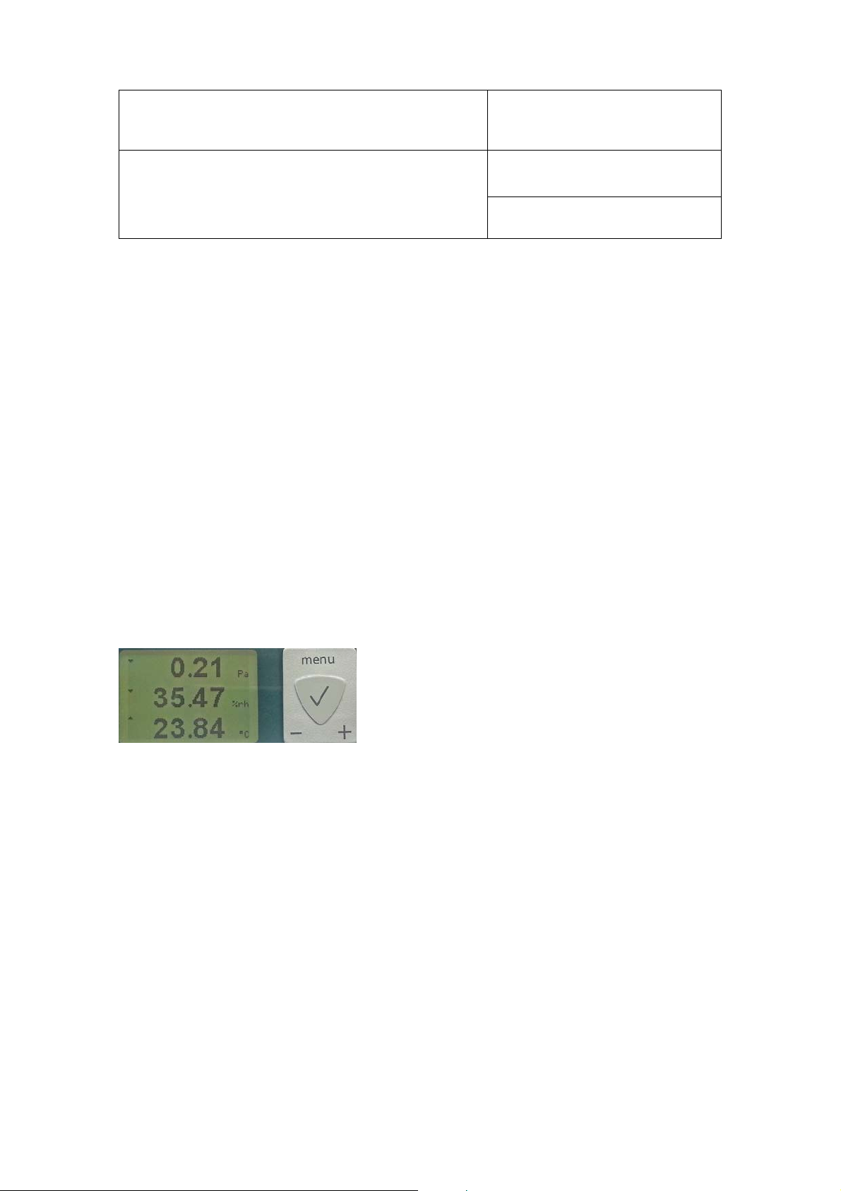
3.8 Display and Keys
The optional LCD for the PF4 has a backlight.
The display unit is configurable. Depending on the version (differential pressure / differential pressure & Pt100
/ differential pressure & HC2 connection), the different parameters can be assigned to the different display lines.
In the full version with HC2 connection, there are three display lines available. They can be assigned the
following parameters:
differential pressure
humidity
temperature
analog input (is only shown when analog input is active)
calculation
no value
The first line of the display shows the differential pressure, the second the relative humidity and the third the
temperature or calculated value such as dew point / frost point. A trend indicator can also be configured for
every line.
The optional LCD for the PF4 has a backlight. The first line of the
display shows the differential pressure, the second the relative
humidity and the third the temperature or calculated value such
as dew point / frost point. The display can be configured to show
a trend indicator in every line.
Figure 4: Display of the PF4 with connected HC2 probe
Keys:
menu: Open menu / Next-higher menu level
+: Increase value
-: Decrease value
: OK / Next-lower menu level
3.8.1 Alarms
Measured values with an alarm are shown with an exclamation mark [!]. Alarms are configured with the HW4
software.
© 2014; Rotronic AG E-M-PF4-V1_00
Page 16

E-M-PF4-V1_00
Document Code Unit
PF4 Differential Pressure Transmitter:
Instruction Manual
Document Title
Rotronic AG
Bassersdorf, Switzerland
Instruction Manual
Document Type
Page
16 of 54
3.8.2 Decimals
The PF4 adjusts the number of decimal places automatically on the basis of the current measured value. The
display therefore always shows the measured value clearly with the corresponding number of significant
decimals.
3.9 HW4 Software Compatibility
PF4 differential pressure transmitters are integrated completely in the HW4 software - devices with only
differential pressure measurement or additional Pt100 connector from V3.2 and later, and with HC2 connection
option from V3.4.
PF4 Version Supported in HW4 from Version:
PF4 without additional connector
PF4 with B4 connector
PF4 with E2 connector HW4 V3.4
HW4 V3.2
© 2014; Rotronic AG E-M-PF4-V1_00
Page 17
E-M-PF4-V1_00
Document Code Unit
PF4 Differential Pressure Transmitter:
Instruction Manual
Document Title
Rotronic AG
Bassersdorf, Switzerland
Instruction Manual
Document Type
Page
17 of 54
4 Mechanical Installation
4.1 General
The PF4 can be mounted on a wall or on a DIN top-hat rail. The position of the device and thus of the differential
pressure sensor has no influence on measurement, i.e. the device is not sensitive to position. However, for
exact measurement, the device must not move and must not be exposed to vibrations.
IMPORTANT:
After complete mechanical installation, the atmospheric pressure must be programmed in the device as
described in chapter 6.1.1.
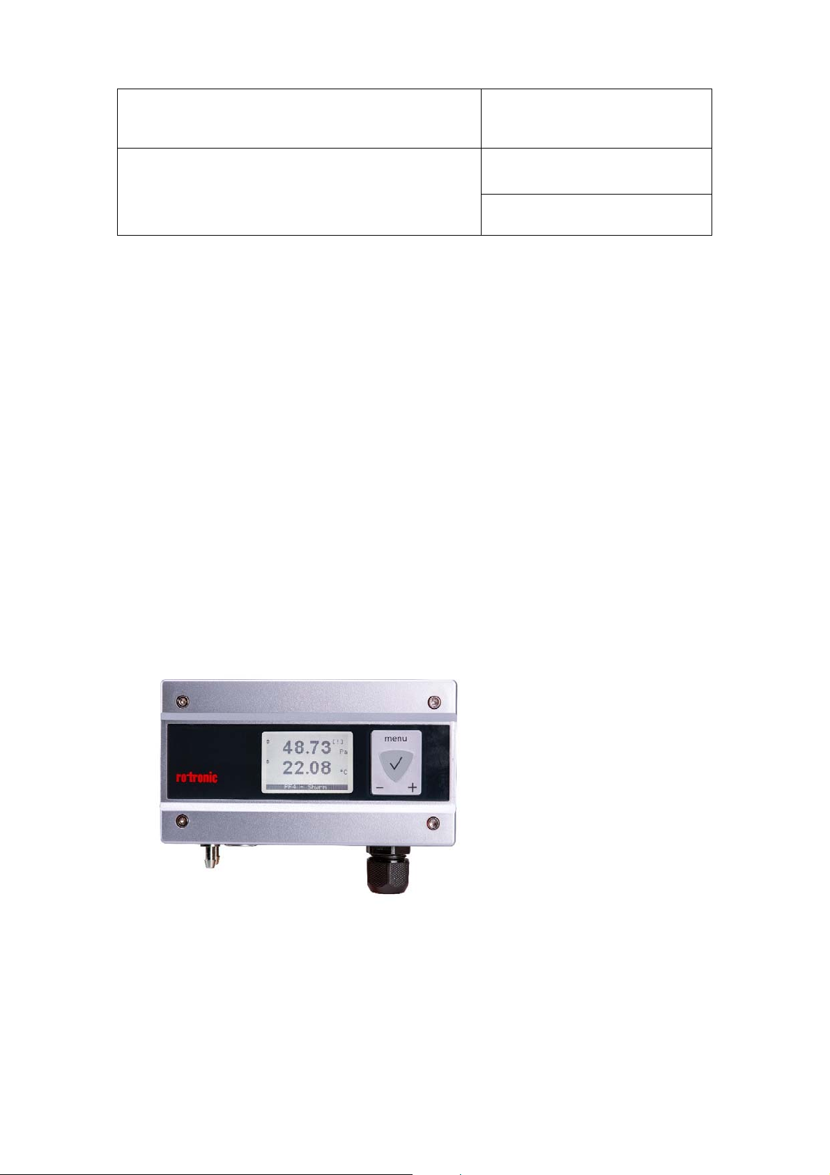
4.2 Housing
The housing can be opened by unscrewing four screws. The screw breakthroughs for wall mounting and
electrical connections for the power supply, analog outputs, service interface and the relay are to be found inside
the housing.
Figure 5: Front view PF4 housing
© 2014; Rotronic AG E-M-PF4-V1_00
Page 18

E-M-PF4-V1_00
Document Code Unit
PF4 Differential Pressure Transmitter:
Instruction Manual
Document Title
4.3 Mounting
Method 1: The PF4 comes with two screws, two wall plugs and two rubber
washers. There are two screw depressions in the bottom part of the housing
(closed on delivery). Use the template delivered with the PF4 to drill the holes
in the wall and put in the wall plugs. Place a rubber washer under each screw
head. Put a screw in each depression and push through the bottom of the
depression.
Method 2: The mounting kit AC5002 (not included) is needed for mounting on
a DIN top-hat rail (35 mm / 1 3/8"). The mounting kit consists of two clips, which
are fastened to the back of the housing with the screws supplied.
Figure 6: Mounting kit AC5002 and drilling points for wall mounting
Rotronic AG
Bassersdorf, Switzerland
Instruction Manual
Document Type
Page
18 of 54
4.4 Differential Pressure Connection
Tubes with an internal diameter of 4 mm can be connected. The tubes must be fastened securely so that
they do not move or vibrate during operation. This would falsify the measurement.
Configuration of differential pressure connections:
+: Positive pressure connection
-: Negative pressure connection
Figure 7: Differential pressure connections and E2 socket on the bottom side of the PF4
© 2014; Rotronic AG E-M-PF4-V1_00
Page 19

E-M-PF4-V1_00
Document Code Unit
PF4 Differential Pressure Transmitter:
Instruction Manual
Document Title
Rotronic AG
Bassersdorf, Switzerland
Instruction Manual
Document Type
Page
19 of 54
4.5 HC2 / Analog Connection
The PF4 can optionally be ordered with an E2 socket. This interface and its possible uses are described below.
4.5.1 Use of HC2 Probe
The PF4 can optionally be set up for a HC2 probe. After connection of
a HC2 probe, it is possible to measure and display three parameters:
Differential pressure
Humidity
Temperature / Calculation
Figure 8: E2 and differential pressure connection on the bottom side
of the PF4
All HC2 probes currently available can be connected. The measured data of the HC2 probe is evaluated digitally
and shown on the display. Two of the measured values can be assigned to the analog outputs (chapter 6.2 )
and processed further. The optional Ethernet interface (chapter 6.3 ) of the PF4 can output all measured values.
4.5.2 Use of Analog Input
The device menu is used to switch between use of a HC2 probe and an analog third-party probe. The display
of the PF4 switches automatically to the units mA / mV of the analog input.
The input is reconfigured with the device menu:
MENU > Probe Information > Sensor Type
Select between the following options:
HC2 Digital HC2 probes are read out
Analog In Analog input is used
The PF4 then asks the user to confirm the sensor change and restarts with the corresponding display
configuration.
Remark:
© 2014; Rotronic AG E-M-PF4-V1_00
Page 20

E-M-PF4-V1_00
Document Code Unit
PF4 Differential Pressure Transmitter:
Instruction Manual
Document Title
Rotronic AG
Bassersdorf, Switzerland
Instruction Manual
Document Type
Page
20 of 54
The PF4 does not contain a power supply for an analog third-party probe. If adequate, the power supply for the
HC2 probe can be used via the pins V+ and GND (see Figure 9).
When using an analog probe, be sure to define both the voltage signal range and the measurement range of
the probe. The HW4 software requires definition of the measurement range for an analog probe. The HW4
software can also be used to change the probe type for the input.
Pin Configuration E2 Connection
Figure 9: Pin configuration of the E2 socket (view from front)
1) V+: Digital probe: 3.3 VDC, 10 mA
2) GND: Digital and supply ground
3) RXD: UART digital probe
4) TXD: UART digital probe
5) ANA IN: Analog input: 0…3.2 V / 0…25 mA
6) NU: Not used
7) AGND: (Analog GND)
© 2014; Rotronic AG E-M-PF4-V1_00
Page 21

E-M-PF4-V1_00
Document Code Unit
Rotronic AG
Bassersdorf, Switzerland
PF4 Differential Pressure Transmitter:
Instruction Manual
Document Title
4.6 Pt100 Connection
The PF4 comes optionally with a Pt100 connection with four-pin connector
(Binder series 711) for all Pt100 probes from ROTRONIC and all variants
of third-party Pt100 probes.
Figure 10: Pt100 and differential pressure connection on the bottom side of the PF4
Instruction Manual
Page
21 of 54
Document Type
Wiring Diagram / Pin Configuration
Figure 11 shows the pin configuration and wiring diagram for the Pt100 probe.
Figure 11: Four-wire wiring of the Pt100
© 2014; Rotronic AG E-M-PF4-V1_00
Page 22

E-M-PF4-V1_00
Document Code Unit
PF4 Differential Pressure Transmitter:
Instruction Manual
Document Title
Rotronic AG
Bassersdorf, Switzerland
Instruction Manual
Document Type
Page
22 of 54
5 Electrical Installation
This section describes the general safety precautions for electric wiring.
5.1.1 Cable Grip and Cable Specifications
The PF4 comes with a M16 cable grip with screw cable gland. The M16 cable grip offers effective sealing if
cables with external diameters of 6 to 7 mm (0.236 to 0.275 inch) with connection wires per 18 AWG are used.
5.1.2 General Connection Information
Heavy machinery and measuring instruments should not share the same electric cables for power supply. If this
cannot be avoided, noise filters and surge protectors should be used, as integrated in most UPS devices.
5.1.3 Signal Cable Information
The following guidelines are derived from the European standard EN 50170 for the transmission of signals by
copper wires. Note on installation planning: when determining the position of machinery and equipment, the
rules given in EN 50170 should be followed with due regard to local circumstances.
All ROTRONIC products are tested for electromagnetic compatibility according to EMC Directive 2004/108/EC
and the following European standards:
- EN 61000-6-1: 2007, EN 61000-6-2: 2005
- EN 61000-6-3: 2007, EN 61000-6-4: 2007
Whenever the level of electromagnetic interference is expected to be high, both the devices and signal cables
should be placed as far away as possible from the source of interference.
In general, signal cables should be installed in bundles or channels / conduits, separate from other cables as
indicated in the table below:
© 2014; Rotronic AG E-M-PF4-V1_00
Page 23

E-M-PF4-V1_00
Document Code Unit
PF4 Differential Pressure Transmitter:
Instruction Manual
Document Title
Bus signals such as RS-485
Data signals for PCs, printers, etc.
Shielded analog inputs
Unshielded DC voltage (<= 60 V)
Shielded process signals (<= 25 V)
Unshielded AC voltage (<= 25 V)
Coaxial cables for CRT monitors
in common bundles or channels / conduits
Rotronic AG
Bassersdorf, Switzerland
Instruction Manual
Document Type
Page
23 of 54
DC voltage from 60 V to 400 V (unshielded)
AC voltage from 25 V to 400 V (unshielded)
DC and AC voltage > 400 V (unshielded)
Telephone lines
Lines leading into EX-rated areas
in separated bundles or channels / conduits,
without minimum distance
in separated bundles or channels / conduits,
without minimum distance
© 2014; Rotronic AG E-M-PF4-V1_00
Page 24

E-M-PF4-V1_00
Document Code Unit
Rotronic AG
Bassersdorf, Switzerland
PF4 Differential Pressure Transmitter:
Instruction Manual
Document Title
5.2 Wiring
This section describes the wiring of the device with connection possibilities.
5.2.1 Electrical Diagrams
The PF4 is wired with a four-pin connection cable
for transmission of the electrical power and
measured values. The maximum permissible
cable length depends on the voltage drop caused
by the flow of current to the devices connected to
the PF4 outputs. The effective load of a PF4 output
comprises the cable and load resistance and
should amount to at least 1000 ohm. The cable
resistance should not be more than 1/1000 of the
load resistance.
Figure 12: Voltage outputs
Instruction Manual
Page
24 of 54
Document Type
The maximum permissible length of the cable
connecting the unit to other devices is determined
by the total resistance resulting from addition of
the cable resistance and resistance of the devices
connected to the unit in series. This resistance
should not exceed 500 ohm (load).
Figure 13: Current outputs
© 2014; Rotronic AG E-M-PF4-V1_00
Page 25

E-M-PF4-V1_00
Document Code Unit
PF4 Differential Pressure Transmitter:
Instruction Manual
Document Title
Terminals Description
Rotronic AG
Bassersdorf, Switzerland
Instruction Manual
Document Type
Page
25 of 54
K2-1: V-
K2-2: V+
K2-3: Protective ground
Ethernet
(optional)
Figure 14: Connection terminals on the board
Note:
Terminal K2-3 (protective ground) is connected with GND due to the closed solder jumper B5. To remove this
connection, open solder jumper B5.
Warning:
Before connecting the PF4 to an active Ethernet network, make sure it is configured correctly for IP
communication. Otherwise conflicts could disturb communication in the network.
K3-1: NC Normally closed – relay not energized
K3-2: COM Common – common contact
K3-3: NO Normally open – relay energized
K4-1: OUT1
K4-2: OUT2
K4-3: GND
K4-4: GND Ground (connected to other GND)
Power supply: 15…40 VDC (-) or
14…28 VAC
Power supply: 15…40 VDC (+) or
14…28 VAC
Differential pressure analog output
(+)
Temperature / Humidity
analog output (+)
Ground (connected to other GND),
see note below
© 2014; Rotronic AG E-M-PF4-V1_00
Page 26

E-M-PF4-V1_00
Document Code Unit
PF4 Differential Pressure Transmitter:
Instruction Manual
Document Title
6 Operation
This chapter describes handling of the device in operation.
6.1 Differential Pressure
Rotronic AG
Bassersdorf, Switzerland
Instruction Manual
Document Type
Page
26 of 54
6.1.1
Ambient Pressure
The differential pressure sensor in the device is dependent on the local absolute ambient atmospheric pressure
P
. This must be communicated to the PF4 per display or HW4 software in order to attain the measuring
abs
accuracy named in the data sheet. P
can be determined with a barometer.
abs
Note:
The "atmospheric pressure at the place of use" QFE is to be used and not the "normalized atmospheric
pressure" QFF, which is communicated in weather forecasts (see also http://de.wikipedia.org/wiki/QFE#QFE).
The ambient pressure enters the measurement as follows and the differential pressure is compensated
automatically on the basis of the ambient pressure setting:
Formula Legend
∆
∆
1000
∆
∆
Real differential pressure [Pa]
Measured differential pressure [Pa]
Ambient pressure [hPa]
Relationship between altitude and pressure (on average):
Formula:
1
where 1013.25
.
ö
© 2014; Rotronic AG E-M-PF4-V1_00
Page 27

E-M-PF4-V1_00
Document Code Unit
PF4 Differential Pressure Transmitter:
Instruction Manual
Document Title
1050
1000
950
900
850
800
750
700
Atmosphericpressure[hPa]
650
Rotronic AG
Bassersdorf, Switzerland
Instruction Manual
Document Type
Page
27 of 54
600
Altitude[m]
Figure 15: Graph showing the correlation between atmospheric pressure and altitude
© 2014; Rotronic AG E-M-PF4-V1_00
Page 28

E-M-PF4-V1_00
Document Code Unit
PF4 Differential Pressure Transmitter:
Instruction Manual
Document Title
Rotronic AG
Bassersdorf, Switzerland
Instruction Manual
Document Type
Page
28 of 54
6.1.2 Dust and Humidity
Since the flow of air through the differential pressure sensor is very low (max. 180 µl/min), dust particles already
settle on the inside walls of the inlet tube and do not reach the sensor. The device is thus largely insensitive to
dust in the air being measured. The same applies to condensing air in the tube. As a result very little humidity
is transported to the sensor.
6.2 Analog Outputs
The analog outputs of the PF4 are configured at the factory according to the order specifications. If a change
is required use HW4 software to modify the instrument configuration.
6.3 Ethernet Connection
The PF4 with digital option uses the standard RO-ASCII protocol. Users who wish to evaluate the measured
data without ROTRONIC HW4 software are asked to consult ROTRONIC.
The Ethernet interface of the PF4 can be used best together with a PC with installed HW4 software (version 3.2
or later). Users may in principle access the measured data of the PF4 with any communication software. This
is described in detail in the document E-M-AC3000-CP.
Before connecting the PF4 to an active Ethernet network, it is first necessary to configure the TCP/IP settings.
You can find instructions for this in the HW4 manual E-M-HW4v3-Main (chapter 7.4) and the technical
guidelines E-M-TCPIP-Conf. The manuals can be downloaded from the website www.rotronic.com.
WARNING:
Before connecting the PF4 to an active Ethernet network, make sure it is configured correctly for IP
communication. Otherwise conflicts could disturb communication in the network.
© 2014; Rotronic AG E-M-PF4-V1_00
Page 29

E-M-PF4-V1_00
Document Code Unit
PF4 Differential Pressure Transmitter:
Instruction Manual
Document Title
Rotronic AG
Bassersdorf, Switzerland
Instruction Manual
Document Type
Page
29 of 54
6.4 Analog Input
The measurement range for the input voltage lies between 0 and 3.2 V if a voltage input is configured and from
0...25 mA if a current input is configured. It must be stipulated in the order code whether the analog input is to
be configured as current or voltage measurement (see also chapter 3.4 ).
6.4.1 Display for Analog Input
The measured values of the analog input are shown in the display in mV / mA by default. For the analog input,
input signals smaller than 0 mV / mA are shown as ˅˅.˅˅. Input signals greater than 3.2 V / 25 mA are shown
in the display as
the effective input signal measured lies outside the permissible range.
The number of decimals shown in the display of the analog input is adjusted automatically in dependence on
the input or scale value.
˄˄.˄˄. This display is also shown if a display calculated via Range and Scale is wanted
and
6.4.2 Unit Systems
The default analog input unit is mV / mA. A user-specific unit can be configured in the HW4 software (e.g. %,
mbar, etc.). There are a maximum of four characters available for this.
6.4.3 Accuracy
The accuracy of the analog input is better than 0.5% of the displayed value and additionally ±1 digit of the last
place of the display.
© 2014; Rotronic AG E-M-PF4-V1_00
Page 30

E-M-PF4-V1_00
Document Code Unit
PF4 Differential Pressure Transmitter:
Instruction Manual
Document Title
Rotronic AG
Bassersdorf, Switzerland
Instruction Manual
Document Type
Page
30 of 54
6.4.4 Scaling of the Analog Input
The analog input can be scaled within the range 0…3.2 V / 0…25 mA. If, for example, only 1...2.5 V are to be
shown in the display due to the application or a connected third-party probe, the analog input must be scaled
accordingly. Figure 16 illustrates scaling of the analog input.
Legend for
Input-Range: 0…3.2 V / 0…25 mA
RangeLo: 0 V / 0 mA (lowest input value)
RangeHi: 3.2 V / 25 mA (highest input value)
ScaleLo: Bottom scale limit (min. value shown in display)
ScaleHi: Top scale limit (max. value shown in display)
Figure 16: Graphic representation of scaling the analog input
Figure16:
Example:
An ambient pressure sensor with an analog output of 500…1000 mV (900…1100 hPa) is to be connected and
its signal shown in hPa. The Input-Range with the limits RangeLo = 500 mV and RangeHi = 1000 mV and the
display range Scale with ScaleLo = 900 and ScaleHi = 1100 mean that an input voltage of 500 mV shows the
value 900 in the display and an input voltage of 1000 mV the value 1100. The unit is configured with the HW4
software as "hPa".
Remark on PF4 with HC2 and analog input:
The formula for calculation of the Display-Value is:
© 2014; Rotronic AG E-M-PF4-V1_00
∗
Page 31

E-M-PF4-V1_00
Document Code Unit
PF4 Differential Pressure Transmitter:
Instruction Manual
Document Title
Examples:
Rotronic AG
Bassersdorf, Switzerland
Instruction Manual
Document Type
Page
31 of 54
6.4.5 Output Scale
The display range (Scale = ScaleHi - ScaleLo) of the Display-Value can be selected freely within the complete
display range (Display-Scale), but may not exceed the maximum display range of
-9,999…99,999.
The output range (Output-Range = RangeHi - RangeLo) of the output signal (Output-Value) can be selected
freely within the complete output range (Voltage- / Current-Range), but may not exceed the maximum output
range, cf. chapter 3.5 (0…1 V / 0…5 V / 0…10 V / 0…24 mA / 4…24 mA). Fixed values (Fix-Value) are treated
in the same way as Display-Values.
Figure 17: Graphic representation of scaling the analog output
© 2014; Rotronic AG E-M-PF4-V1_00
Page 32

E-M-PF4-V1_00
Document Code Unit
PF4 Differential Pressure Transmitter:
Instruction Manual
Document Title
Remark on PF4 with HC2 and analog input:
The formula for calculation of the Output-Value is:
Examples:
∗
Rotronic AG
Bassersdorf, Switzerland
Instruction Manual
Document Type
Page
32 of 54
© 2014; Rotronic AG E-M-PF4-V1_00
Page 33

E-M-PF4-V1_00
Document Code Unit
PF4 Differential Pressure Transmitter:
Instruction Manual
Document Title
6.5 Display and Keys
Figure 18: Display of the PF4 with connected HC2 probe
Rotronic AG
Bassersdorf, Switzerland
Instruction Manual
Document Type
Page
MENU key:
open / close menu
ENTER key:
select menu point
Menu navigation keys + / -
change value: increase / decrease
33 of 54
Note:
Unauthorized use of the menu can be prevented by locking the setting "Display Menu" (using the HW4 software
> Device Manager > Display).
The display shows different measured values in dependence on the configuration of the device.
Device Variant Displays Units
© 2014; Rotronic AG E-M-PF4-V1_00
Page 34

E-M-PF4-V1_00
Document Code Unit
PF4 Differential Pressure Transmitter:
Instruction Manual
Document Title
Rotronic AG
Bassersdorf, Switzerland
Instruction Manual
Document Type
Page
34 of 54
Differential pressure
Differential pressure & Pt100
connection
Differential pressure in Pascal
[Pa]
Differential pressure in Pascal
[Pa]
Temperature in degrees Celsius
[°C]
© 2014; Rotronic AG E-M-PF4-V1_00
Page 35

E-M-PF4-V1_00
Document Code Unit
PF4 Differential Pressure Transmitter:
Instruction Manual
Document Title
Rotronic AG
Bassersdorf, Switzerland
Instruction Manual
Document Type
Page
35 of 54
Differential pressure [Pa]
Relative humidity [%RH]
Temperature [°C]
Differential pressure [Pa]
Relative humidity [%RH]
Differential pressure & HC2
connection
Remark:
It is possible to switch between display of the temperature and the calculations by pressing the Enter key [].
It is likewise possible to change between use of the HC2 probe and analog input in the device menu, as
described in chapter 4.5.2.
Pressing the – and + keys switches between the different calculations:
Ew [hPa], E [hPa], Ds [g/m³], R (g/kg), Q [g/kg], Dv [g/m³], H [kJkg], Tw [°C], Fp [°C], Dp [°C].
Calculation [°C]
Differential pressure [Pa]
Voltage [mV]
Differential pressure [Pa]
Current [mA]
© 2014; Rotronic AG E-M-PF4-V1_00
Page 36

E-M-PF4-V1_00
Document Code Unit
PF4 Differential Pressure Transmitter:
Instruction Manual
Document Title
Rotronic AG
Bassersdorf, Switzerland
Instruction Manual
Document Type
Page
36 of 54
6.5.1 PF4 Menu
The menu structure depends on the hardware configuration of the device. The following three variants are
possible:
Only differential pressure
Differential pressure & Pt100 connection
Differential pressure & HC2 connection
Variant 1: Only differential pressure
Main Menu
Menu Navigation (valid for all menus)
Select Options
(Enter key) Selection of the menu point
Device Settings
Device Information
Settings for Differential Pressure
or menu
+ Line up; option right
- Line down; option left
Select Options
Units
Backlight
Contrast 0…99 (suitable setting 15…40)
Trend
Pressure
Value 1
The device information cannot be changed (except for "Name" and "Address").
"Name" and "Address" can be set with the HW4 software.
Select Options
Unit
Return; menu one level up
Unit for the ambient pressure (Pressure):
Metric, English
On, Off, Key Press
On, Off
Ambient pressure (suitable setting: 950 - 1050 hPa):
0…9,999 hPa (Units: Metric)
0…9,999 inHg (Units: English)
Main display: None, DiffPress
Unit for the differential pressure: Pa, inH
mbar, mmHg, mmH
O, Torr, g/cm2
2
0, mpsi,
2
© 2014; Rotronic AG E-M-PF4-V1_00
Page 37

E-M-PF4-V1_00
Document Code Unit
Rotronic AG
Bassersdorf, Switzerland
PF4 Differential Pressure Transmitter:
Instruction Manual
Document Title
Filters
RefValue Current differential pressure can be changed
<Adjust> Applies change to RefValue
<Zero Adjust> Performs a zero adjustment
<Reset Adjustment> Cancels the last change (<Adjust>, <Zero Adjust>)
Filter value (0 = fast, 13 = very slow): 0…13 (suitable
setting 0…7)
Instruction Manual
Page
37 of 54
Document Type
© 2014; Rotronic AG E-M-PF4-V1_00
Page 38

E-M-PF4-V1_00
Document Code Unit
PF4 Differential Pressure Transmitter:
Instruction Manual
Document Title
Variant 2: Differential pressure & Pt100 connection
Main Menu
Menu Navigation (valid for all menus)
Select Options
(Enter key)
Selection of the menu point
Rotronic AG
Bassersdorf, Switzerland
Instruction Manual
Document Type
Page
38 of 54
Device Settings
Device Information
Settings for Differential Pressure
Pt100 Adjust (1)
or menu
+ Line up; option right
- Line down; option left
Select Options
Units
Backlight
Contrast 0…99 (suitable setting 15…40)
Trend
Pressure
Value 1
Value 2
The device information cannot be changed (except for "Name" and "Address").
"Name" and "Address" can be set with the HW4 software.
Select Options
Unit
Filters
RefValue Current differential pressure can be changed
<Adjust> Applies change to RefValue
<Zero Adjust> Performs a zero adjustment
<Reset Adjustment> Cancels the last change (<Adjust>, <Zero Adjust>)
Return; menu one level up
Unit for the ambient pressure (Pressure):
Metric, English
On, Off, Key Press
On, Off
Ambient pressure (suitable setting: 950 - 1050 hPa):
0…9,999 hPa (Units: Metric)
0…9,999 inHg (Units: English)
Main display: None, DiffPress, TempPt100
Main display: None, DiffPress, TempPt100
Unit for the differential pressure: Pa, inH
mmHg, mmH
Filter value (0 = fast, 13 = very slow): 0…13 (suitable
setting 0…7)
O, Torr, g/cm2
2
0, mpsi, mbar,
2
© 2014; Rotronic AG E-M-PF4-V1_00
Page 39

E-M-PF4-V1_00
Document Code Unit
PF4 Differential Pressure Transmitter:
Instruction Manual
Document Title
Display when a Pt100 sensor is not connected
Pt100 Adjust (2)
Display when a Pt100 sensor is connected
Select Options
RefValue The current temperature shown can be changed
<Adjust> Applies change to RefValue
<Reset Adjustment> Cancels the last change made with <Adjust>
Variant 3: Differential pressure & HC2 connection
Main Menu
Menu Navigation (valid for all menus)
Select Options
(Enter key) Selection of the menu point
Rotronic AG
Bassersdorf, Switzerland
Instruction Manual
Document Type
Page
39 of 54
Device Settings
Device Information
or menu
+ Line up; option right
- Line down; option left
Select Options
Units
Backlight
Contrast 0…99 (suitable setting 15…40)
Trend
Pressure
Value 1 None, DiffPress, Humi HC2, Temp HC2, Calc
Value 2
Value 3
The device information cannot be changed (except for "Name" and "Address").
"Name" and "Address" can be set with the HW4 software.
Return; menu one level up
Unit for the ambient pressure (Pressure):
Metric, English
On, Off, Key Press
On, Off
Ambient pressure (suitable setting: 950 - 1050 hPa):
0…9,999 hPa (Units: Metric)
0…9,999 inHg (Units: English)
None, DiffPress, Humi HC2, Temp HC2, Calc
None, DiffPress, Humi HC2, Temp HC2, Calc
© 2014; Rotronic AG E-M-PF4-V1_00
Page 40

E-M-PF4-V1_00
Document Code Unit
PF4 Differential Pressure Transmitter:
Instruction Manual
Document Title
Settings for Differential Pressure
Select Options
Unit for the differential pressure: Pa, inH
mmHg, mmH
Filter value (0 = fast, 13 = very slow): 0…13 (suitable
setting 0…7)
Select sensor: HC2, Analog In
Probe Information (1)
Unit
Filters
RefValue Current differential pressure can be changed
<Adjust> Applies change to RefValue
<Zero Adjust> Performs a zero adjustment
<Reset Adjustment> Cancels the last change (<Adjust>, <Zero Adjust>)
Display when a HC2 sensor is not connected
Select Options
Sensor Type
Rotronic AG
Bassersdorf, Switzerland
Instruction Manual
Document Type
40 of 54
0, mpsi, mbar,
2
O, Torr, g/cm2
2
Page
Probe Information (2)
Humidity Adjust (1)
Humidity Adjust (2)
Display when a HC2 sensor is connected
Select Options
Version HC2 sensor: current firmware version
Serial No. HC2 sensor: serial number
Address HC2 sensor: sensor address
Name HC2 sensor: sensor name
SensorTest HC2 sensor: quality of sensor
Record
SensorType
Display when a HC2 sensor is not connected
Display when a HC2 sensor is connected
Select Options
RefValue Current relative humidity can be changed
Acquired
<Acquire>
<Delete>
HC2 sensor: Off, On
Select sensor: HC2, Analog In
© 2014; Rotronic AG E-M-PF4-V1_00
Page 41

E-M-PF4-V1_00
Document Code Unit
PF4 Differential Pressure Transmitter:
Instruction Manual
Document Title
<Adjust> Applies change to RefValue
Temperature Adjust (1)
Display when a HC2 sensor is not connected
Temperature Adjust (2)
Display when a HC2 sensor is connected
Select Options
RefValue The current temperature can be changed
<Adjust> Applies change to RefValue
Rotronic AG
Bassersdorf, Switzerland
Instruction Manual
Document Type
Page
41 of 54
Exchange Sensor
Exchange Sensor is started after selecting Analog In in menu Probe
Information
The HC2 sensor can be substituted by an analog input (depending on order
code, for current or voltage measurement).
The action is only started after confirmation by pressing the Enter key [].
If the Enter key [] is not pressed within about 10 seconds, the device
returns to the menu Probe Information.
Exchange HC2 sensor for the analog input and press any key
If a key is not pressed within about 20 seconds, the device starts
automatically with the new settings.
The device is started with the new settings.
Summary of procedure:
MENU > Probe Information > Enter > Sensor Type HC2 > Sensor Type Analog In
> Enter > Change Sensors > Any Key
© 2014; Rotronic AG E-M-PF4-V1_00
Page 42

E-M-PF4-V1_00
Document Code Unit
PF4 Differential Pressure Transmitter:
Instruction Manual
Document Title
Rotronic AG
Bassersdorf, Switzerland
Instruction Manual
Document Type
Page
42 of 54
6.6 Relay
The relay can be used in operation as an alarm switch contact. The functions have already been described in
section 3.6 . The relay is configured with the HW4 software, as described in the manual E-M-HW4v3-P-001.
6.6.1 Connections
The relay switch contacts are located at terminal block K3 (see Figure 14).
Connection Designation Description
COM Common Center tap of the change-over switch
NO Normally open Open when relay is not energized, closed when relay is energized
NC Normally closed Closed when relay is not energized, open when relay is energized
© 2014; Rotronic AG E-M-PF4-V1_00
Page 43

E-M-PF4-V1_00
Document Code Unit
PF4 Differential Pressure Transmitter:
Instruction Manual
Document Title
Rotronic AG
Bassersdorf, Switzerland
Instruction Manual
Document Type
Page
43 of 54
7 Maintenance
Warning:
If only the service cable AC3009 is used to supply power to the PF4, the differential pressure shown will not be
correct because the voltage supply to the electronics is insufficient. For calibration or adjustment with the HW4
software, therefore, the power must be supplied via terminal block K2 in the bottom part of the housing.
7.1 Service Cable
Suitable service cables
AC3006: requires additional power supply to the device
AC3009: supplies the device directly with 5 VDC, differential pressure measurement will,
however, not be correct without external power supply
7.2 Service Port
The Mini-USB service port is located inside the device. The device must be opened by unscrewing the four
screws on the front of the housing in order to gain access to the Mini-USB service port.
Remark: AC3006 / AC3009 may be used as service cable.
Figure 19: Location of the service port on the top side of the circuit board
© 2014; Rotronic AG E-M-PF4-V1_00
Page 44

E-M-PF4-V1_00
Document Code Unit
PF4 Differential Pressure Transmitter:
Instruction Manual
Document Title
Rotronic AG
Bassersdorf, Switzerland
Instruction Manual
Document Type
Page
44 of 54
7.3 Device Calibration and Adjustment Procedure
Both the differential pressure sensor and the corresponding electronics are very stable and require no
maintenance. They do not normally need to be changed or recalibrated after factory calibration. For maximum
accuracy, however, we recommend regular calibration of the device and adjustment when necessary.
Important:
When carrying out calibration or adjustment work on the open device, make sure you do not touch either the
sensor or the compressed air tubes.
7.3.1 Adjust Differential Pressure
The differential pressure can be adjusted at two points.
Zero
Any reference point in the sensor measurement range
Zero Adjustment
1. Connect the pressure connections with a short tube
2. Select "<Zero Adjust>" in MENU > Differential Pressure
After successful zero adjustment, "OK" is shown in the display.
Reference Value Adjustment
1. Apply a defined differential pressure or determine the current differential pressure with a reference
instrument connected in parallel.
2. Enter the reference value determined in MENU > Differential Pressure > RefValue.
3. Select "<Adjust>" in MENU > Differential Pressure.
After successful adjustment, "OK" is shown in the display.
Reset Adjustment
The following procedure is used to reset adjustment to the factory setting.
1. Select "<Reset Adjustment>" in MENU > Differential Pressure
After successful resetting of the adjustment, "OK" is shown in the display.
© 2014; Rotronic AG E-M-PF4-V1_00
Page 45

E-M-PF4-V1_00
Document Code Unit
PF4 Differential Pressure Transmitter:
Instruction Manual
Document Title
Rotronic AG
Bassersdorf, Switzerland
Instruction Manual
Document Type
Page
45 of 54
7.3.2 Adjust Pt100
Reference Value Adjustment
1. Enter a defined reference value with a Pt100 simulator or record the current nominal temperature with
a reference instrument.
2. Enter the reference value determined in MENU > Pt100 > RefValue.
3. Select "<Adjust>" in MENU > Pt100.
After successful adjustment, "OK" is shown in the display.
Reset Adjustment
The following procedure is used to reset adjustment to the factory setting.
1. Select "<Reset Adjustment>" in MENU > Pt100
After successful resetting of the adjustment, "OK" is shown in the display.
© 2014; Rotronic AG E-M-PF4-V1_00
Page 46

E-M-PF4-V1_00
Document Code Unit
PF4 Differential Pressure Transmitter:
Instruction Manual
Document Title
Rotronic AG
Bassersdorf, Switzerland
Instruction Manual
Document Type
Page
46 of 54
7.3.3 Adjust HC2 Probe
Both the Pt100-RTD temperature sensor used in the probe and the corresponding electronics are very stable
and do not normally need to be calibrated after initial factory calibration.
The long-term stability of the HYGROMER humidity sensor from ROTRONIC is normally better than 1 %RH per
year. For maximum accuracy, it is advisable to check the calibration of the probe every six to 12 months.
Applications in which the probe is exposed to considerable contamination could require more frequent checks.
Temperature Adjustment
The optional keypad of the PF4 enables one-point adjustment of the temperature or humidity in relation to a
reference. A one-point adjustment results in the same offset being added to all measured values.
When the temperature is stable, press the MENU key to open the internal menu in the display.
Select Temperature Adjust with the (-) key and press ENTER.
Make sure that the text line beginning with RefValue is selected and press ENTER.
Change the reference value to the temperature reference value with the (+) or (-) key.
Move to the text line Adjust with the (-) key and press ENTER.
The PF4 confirms adjustment with the message "Adjust OK".
Press the MENU key two times to leave the menu and return the PF4 to normal operation.
Note:
The following principle applies: perform temperature adjustment before humidity adjustment.
The calibration point is deleted automatically from the probe memory after adjustment.
Since the PF4 does not have a real-time clock, the date of the adjustment is not written in the probe. If it
is important to record the adjustment date, use the HW4 software to adjust the probe.
© 2014; Rotronic AG E-M-PF4-V1_00
Page 47

E-M-PF4-V1_00
Document Code Unit
PF4 Differential Pressure Transmitter:
Instruction Manual
Document Title
Rotronic AG
Bassersdorf, Switzerland
Instruction Manual
Document Type
Page
47 of 54
Humidity Adjustment
The keypad of the PF4 enables multi-point adjustment of the humidity. The effect of a humidity adjustment
differs in dependence on the number of calibration points entered into the probe memory before adjustment:
One calibration point adds an offset to all measured values.
Two calibration points influence the offset and gain of the measurement curve.
Three or more calibration points influence the offset, gain and linearity of the measurement curve.
For maximum accuracy, three to four calibration points distributed over the measurement range in question
should be used. The calibration points (maximum 100) can be entered in any order, but we recommend working
from low humidity values to high humidity values.
When the humidity is stable, press the MENU key to open the internal menu in the display.
Select Humidity Adjust with the (-) key and press ENTER.
Make sure that the text line beginning with RefValue is selected and press ENTER.
Change the reference value to the reference humidity with the (+) or (-) key.
Move to the text line Acquire with the (-) key and press ENTER.
Note that the counter "Acquired" will be increased by 1 (number of calibration points in probe memory).
When all calibration points have been acquired, move to the text line Adjust with the (-) key and press
ENTER. Only adjust the probe when all calibration points have been acquired.
The PF4 confirms adjustment with the message "Adjust OK".
Press the MENU key two times to leave the menu and return the PF4 to normal operation.
© 2014; Rotronic AG E-M-PF4-V1_00
Page 48

E-M-PF4-V1_00
Document Code Unit
PF4 Differential Pressure Transmitter:
Instruction Manual
Document Title
Rotronic AG
Bassersdorf, Switzerland
Instruction Manual
Document Type
Page
48 of 54
Note:
All calibration points are deleted automatically from the probe memory after adjustment.
The text line Delete can be used to delete all calibration points before probe adjustment.
Since the PF4 does not have a real-time clock, the date of the adjustment is not written in the probe. If it
is important to record the adjustment date, use the HW4 software to adjust the probe.
7.4 Validation of Analog Output Signals
Using the HW4 software, it is possible to set fixed values with which the analog output signals can be validated.
8 Firmware Update
The firmware can be updated with the HW4 software. Firmware updates are available for downloading on the
ROTRONIC website. To update the firmware, the PF4 must be connected to the HW4 with service cable
AC3006. The PF4 must remain connected to the computer throughout the update process and there must be a
stable power supply for the complete duration of the process.
Flashing of the display backlight indicates a firmware update is in progress.
© 2014; Rotronic AG E-M-PF4-V1_00
Page 49

E-M-PF4-V1_00
Document Code Unit
PF4 Differential Pressure Transmitter:
Instruction Manual
Document Title
Rotronic AG
Bassersdorf, Switzerland
Instruction Manual
Document Type
Page
49 of 54
9 Technical Data
General
Device type
Circuit type 3-wire circuit
Mounting types W (Wall)
Power Supply and Connections
Supply voltage (VDD) 15...40 VDC / 14...28 VAC
Rated current consumption DC supply
Rated current consumption AC supply
Electrical connections Terminal block and M16 cable grip, optional RJ-45 Ethernet connector
Polarity protection Protective diode on V+
Humidity and Temperature Measurement
Differential pressure transmitter with analog output signals and optional
Ethernet interface
<70 mA (only analog outputs)
<150 mA (with Ethernet interface)
<70 mA (only analog outputs)
<450 mA (with Ethernet interface)
With HC2
With Pt100
See document E-M-HC2 Probes > Specifications.
Accuracy: ±0.2 °C
Meas. range: -100…200 °C (depending on probe type)
Differential Pressure Measurement
Measurement ranges -25…+25 Pa / -50…+50 Pa / -100…+100 Pa / -250…+250 Pa / -500…+500 Pa
Accuracy ±1.0 %Full Scale Span
Response time sensor 63
Ambient pressure dependence 0.1 %/hPa
Air flow 120 – 180 µl/min
Pressure resistance 2 bar (2,000 hPa)
Long-term stability <0.3 %/year
Adjustment points Zero, reference point
<10 ms (only sensor element)
© 2014; Rotronic AG E-M-PF4-V1_00
Page 50

E-M-PF4-V1_00
Document Code Unit
Rotronic AG
Bassersdorf, Switzerland
PF4 Differential Pressure Transmitter:
Instruction Manual
Document Title
Analog Input
Measurement range
Accuracy 0.5% of current measured value
Temperature dependence
Calculated Parameters
Psychrometric parameters
Startup Time and Measurement Interval
Startup time <5 s (typical)
Measurement interval 1 s (typical)
Voltage: 0…3.2 V
Current: 0…25 mA
Voltage: ±30 mV
Current: ±60 µA
Dew point (Dp) above and below freezing point
Frost point (Fp) below freezing point and dew point above freezing point
Wet bulb temperature (Tw)
Enthalpy (H)
Vapor concentration (Dv)
Specific humidity (Q)
Mixing ratio by weight (R)
Vapor concentration at saturation (Dvs)
Vapor partial pressure (E)
Vapor saturation pressure (Ew)
Instruction Manual
Page
50 of 54
Document Type
© 2014; Rotronic AG E-M-PF4-V1_00
Page 51

E-M-PF4-V1_00
Document Code Unit
PF4 Differential Pressure Transmitter:
Instruction Manual
Document Title
Configurable Analog Outputs
Output 1 Can be assigned to every parameter
Default parameter Differential pressure
Default range Per order code
Output 2 Can be assigned to every parameter
Default parameter Relative humidity / Temperature
Default range Per order code
Rotronic AG
Bassersdorf, Switzerland
Instruction Manual
Document Type
Page
51 of 54
Output 1 and output 2
Signal type
Accuracy analog output
User-configurable range limits -9,999...+99,999 units
Refresh interval 1 s
Short circuit tolerant Yes
Max. load 500 Ω (current output)
Min. load resistance 1000 Ω (voltage output)
0…20 mA
4…20 mA
0…1 V
0…5 V
0…10 V
(user-configurable)
±10 mV (voltage output)
±20 µA (current output)
Digital Interface
Interface type Ethernet, wired
Service Connector
Interface type UART (TTL Level)
Max. length of service cable 5 m (16.4 ft)
© 2014; Rotronic AG E-M-PF4-V1_00
Page 52

E-M-PF4-V1_00
Document Code Unit
PF4 Differential Pressure Transmitter:
Rotronic AG
Bassersdorf, Switzerland
Instruction Manual
Instruction Manual
Document Title
General Specifications
Relay switching capacity <50 VAC / <75 VDC / <1 A
Optional display LC, resolution 1 or 2 decimals, backlight, trend and alarm indicators
Housing material ABS
Page
Housing protection grade
Dimensions 129 x 72 x 45 mm
Weight 240 g
Conformity with S ta n da rds
CE / EMC immunity
Solder type Lead free (RoHS directive)
Fire protection class Corresponds to UL94-HB
FDA / GAMP directives CFR21 Part 11 and GAMP5
Environmental Limits
Storage and transit 0...70 °C / 0...90 %RH, non-condensing
Operation 0...70 °C / 0...90 %RH, non-condensing
IP65 (without Ethernet interface)
IP40 (with Ethernet interface)
EMC Directive 2004/108/EC: EN 61000-6-1: 2007, EN 61000-6-2: 2005
EN 61000-6-3: 2007, EN 61000-6-4: 2007
52 of 54
Document Type
© 2014; Rotronic AG E-M-PF4-V1_00
Page 53

E-M-PF4-V1_00
Document Code Unit
PF4 Differential Pressure Transmitter:
Instruction Manual
Document Title
10 Accessories
10.1 Service Cable
Order Code Description
AC3006
AC3009
Service cable, USB to UART
Service cable, USB to UART with integrated
power supply
Rotronic AG
Bassersdorf, Switzerland
Instruction Manual
Document Type
Page
53 of 54
10.2 Pressure Tubes
AC6001 Connection tube with 4 mm diameter
10.1 Mounting Elements
Order Code Description
Mounting kit for DIN top-hat rail (consisting of
two clips, which are fastened to the back of the
AC5002
housing with the screws supplied).
DIN top-hat rail (35 mm / 1 3/8") not included.
© 2014; Rotronic AG E-M-PF4-V1_00
Page 54

E-M-PF4-V1_00
Document Code Unit
PF4 Differential Pressure Transmitter:
Rotronic AG
Bassersdorf, Switzerland
Instruction Manual
Instruction Manual
Document Title
Page
11 Additional Documents
Document Name Contents
E-M-HC2 Probes HC2 manual
E-M-HW4v3-Main HW4 software main manual
E-M-TCPIP-Conf Manual for Ethernet configuration of ROTRONIC instruments
E-M-AC3000-CP Communication protocol for all AirChip3000 instruments
E-M-HW4v3-P-001 HW4 software manual for PF4
Document Type
54 of 54
12 Document Versions
Doc. Release Date Remark
E-M-PF4-V1_00 March 2014 Release document
© 2014; Rotronic AG E-M-PF4-V1_00
 Loading...