

Page 1
Operation and
Maintenance Manual
V2.0
Dew Point Mirror 473
Page 2

Warranty
MBW Calibration Ltd. (MBW) guarantees that its products are manufactured to the highest quality of
material and workmanship specifications. MBW guarantees the reliability of its products for a period of
24 months from the date of initial shipment when operated in normal use and within the specified design limitations. Under this Warranty, MBW will, at its discretion, repair or replace any component that
upon examination by MBW or its duly authorized representatives proves to be defective during the
warranty period provided the system is returned to the factory for inspection and repair shipping prepaid. Improper or unauthorized maintenance, storage, repair, or alteration of any kind by personnel
other than MBW or its duly authorized representatives may void all warranties. Warranty may also be
voided for misuse, neglect, accident, corrosion, and improper installation. This Warranty is exclusive
and in lieu of any and all other warranties of merchantability, fitness for a particular purpose, or any
other warranty, expressed or implied, and all other liabilities and obligations on the part of MBW. MBW
will not be liable for any other claims or damages, either direct, indirect, or consequential arising out of
the use of its products.
MBW Calibration Ltd
Seminarstrasse 57
CH-5430 Wettingen / Switzerland
+41 56 437 28 30 phone
+41 56 437 28 40 fax
sales@mbw.ch
www.mbw.ch
Subject to change without notice.
For the latest version of this manual please visit our website.
Copyright © 2012
i MBW473_MANUAL_E_V2.0
Page 3

Table of Contents
WARRANTY ..................................................................................................... I
TABLE OF CONTENTS .................................................................................... II
1 INTRODUCTION ......................................................................................... 1
2 QUICK START ............................................................................................ 3
2.1 Unpacking ...................................................................................................................................... 3
2.2 Starting your 473 ........................................................................................................................... 4
2.3 Installing the Measuring Heads ..................................................................................................... 4
2.4 Dew Point Measurement ............................................................................................................... 5
3 GET TO KNOW YOUR 473 .......................................................................... 7
3.1 Front Panel .................................................................................................................................... 7
3.2 Back Panel ................................................................................................................................... 10
3.3 Measuring Heads ......................................................................................................................... 12
3.4 Carrying Handle ........................................................................................................................... 13
4 SYSTEM CONFIGURATION ...................................................................... 15
4.1 The Menu ..................................................................................................................................... 15
4.2 Selection of indicated Parameters ............................................................................................... 16
4.3 Selection of Numeric or Graphic Data Display ............................................................................ 17
4.4 Graph Scaling .............................................................................................................................. 18
4.5 Control Setup ............................................................................................................................... 20
4.6 Selection of Units ......................................................................................................................... 24
4.7 Analog Output Connections ......................................................................................................... 25
4.8 Selection of Color ........................................................................................................................ 28
5 SET UP AND OPERATION ........................................................................ 29
5.1 Measurement Set Up ................................................................................................................... 29
5.2 External Temperature .................................................................................................................. 30
5.3 Application Integration ................................................................................................................. 32
MBW473_MANUAL_E_V2.0 ii
Page 4

6 REMOTE COMMUNICATION .................................................................... 35
6.1 Hardware Connection and Cabling ............................................................................................. 35
6.2 Communication Settings ............................................................................................................. 36
6.3 Command Syntax ........................................................................................................................ 36
6.4 Command Reference .................................................................................................................. 38
7 MAINTENANCE ........................................................................................ 39
7.1 Calibrate the Touch Screen ......................................................................................................... 39
7.2 Ice Test ........................................................................................................................................ 40
7.3 Mirror Cleaning ............................................................................................................................ 42
7.4 Exterior Cleaning ......................................................................................................................... 43
7.5 System Information...................................................................................................................... 44
8 SPECIFICATIONS .................................................................................... 45
9 DRAWINGS .............................................................................................. 46
iii MBW473_MANUAL_E_V2.0
Page 5

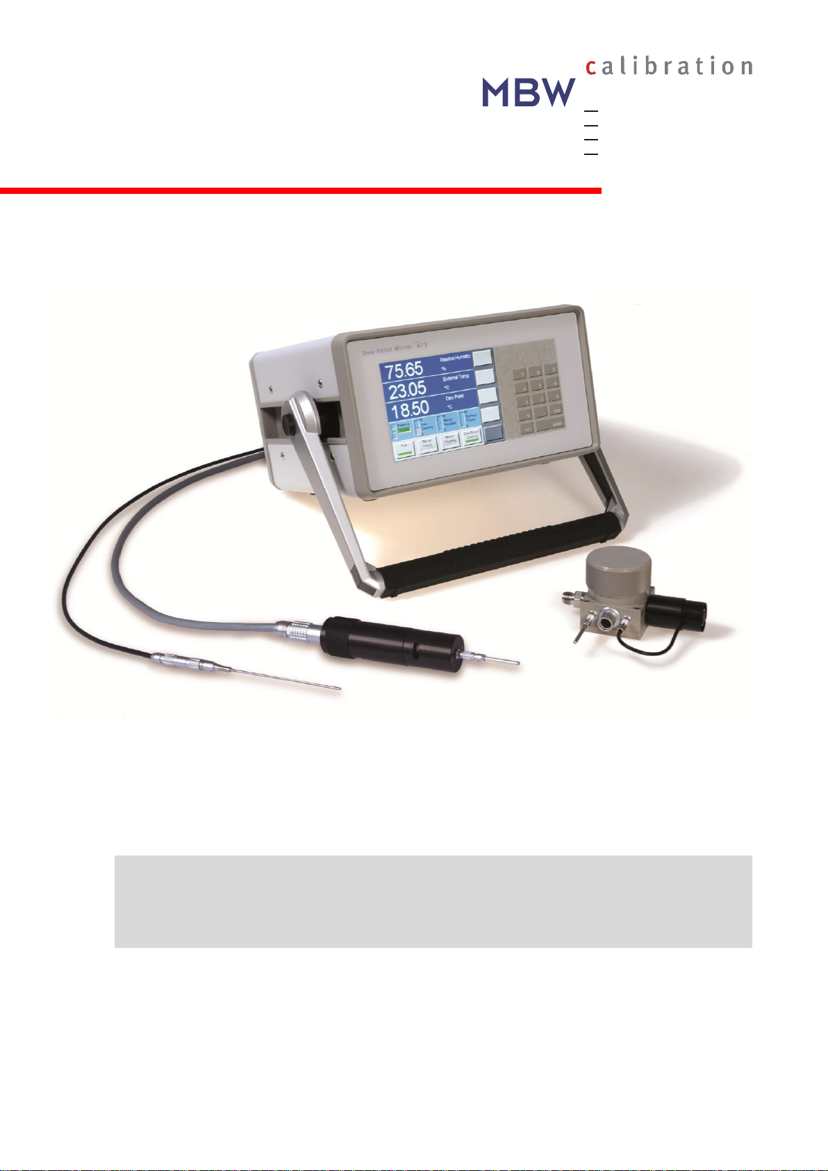
1 Introduction
Precise and Stable Humidity Measurement
With the 473 Dew Point Mirror you are able to perform precise dew point measurements as well as
measurements of other parameters such as relative humidity. The humidity measurement of the 473 is
based on the chilled mirror condensation technology which provides highly precise, stable and repeatable results.
Remote Measuring Heads with Temperature Probe
The 473 features two remote cable mounted measuring head options, the RP2 and the SH2. They are
designed for direct insertion into applications with moving air. Both measuring heads are supplied with
a PRT for precise temperature measurement and for the calculation of relative humidity.
Optional Pressure Measurement
Optionally, the 473 can be ordered with internal pressure measurement capability. This enables the
instrument to compensate for pressure variations at the point of measurement.
LCD Display with Touch Panel
The 473 has a full color LCD touch panel with a high contrast ratio and a wide viewing angle for easy
readability. Data is displayed in large, easy-to-read fonts. Using the on-screen buttons and menus,
you can easily configure each line of the display for a variety of humidity, temperature, and pressure
parameters that may be viewed in either SI or non-SI units.
Calibration
Users can check the 473 calibration at any time using the built-in Ice Test function, which provides
instant verification of system accuracy and integrity.
Connect and Go
The system is ready for immediate use.
MBW473_MANUAL_E_V2.0 1
Page 6

2 MBW473_MANUAL_E_V2.0
Page 7

2 Quick Start
This section guides you through the set-up and the first steps using your 473. It is a summary and
should be used as a general overview and reference only. Do not use it as a substitute for the remainder of the manual. To understand your instrument thoroughly, please read the other sections carefully.
2.1 Unpacking
The 473 is delivered in a custom-fit foam-lined Peli 1550 transport case.
The following items are included in the case:
473 Dew Point Mirror
SH2 or RP2 measuring head (as ordered)
Temperature probe PT(100)
o The RP2 is supplied with a Ø3 x 30 mm PRT and a 0.5 m cable for extended connection
between the probe and the measuring head.
o The SH2 is supplied with a Ø2.1 x 100 mm PRT and a 0.5 m cable to connect the probe
to the measuring head and a 3 m cable to connect the probe directly to the back panel of
the instrument.
2.5 m power cable
2 m measuring head cable
Gas connections 6mm or ¼” Swagelok (SH2 only)
Operation manual
Calibration certificate
Before starting, carefully remove these items from the case and visually check for any signs of damage. If you are missing any item or find them damaged, please call the manufacturer or your local
supplier. Make sure that the power rating on the back label corresponds to your power supply specification.
MBW473_MANUAL_E_V2.0 3
Page 8
2.2 Starting your 473
SH2
RP2
The 473 needs a source of AC power. It will work over a wide power range and will most likely operate
at your local voltage and frequency. Look at the back panel label for the power requirements of your
specific system.
1. Plug the supplied AC power cord into the back of the instrument, then into an AC outlet.
2. Turn the power switch to ON.
The display should become visible within a few seconds. If nothing happens, check the power source.
2.3 Installing the Measuring Heads
Depending on your order, the 473 is supplied with either of the following measuring heads:
The heart of the 473 Dew Point Mirror Instrument is a highly sensitive and accurate measuring head.
Use the 19-pin measuring head cable (2 m) to connect the measuring head to the back panel of the 473.
For further information on the measuring heads, please refer to sections 3.3 ‘Measuring Heads’ and
7.3 ‘Mirror Cleaning’.
4 MBW473_MANUAL_E_V2.0
Page 9
You can test the 473 dew point measurement by measuring the dew point temperature of the room.
First, make sure the measuring head is connected to the back panel of the 473.
Next, start the measurement by pressing the Dew/Frost Control key. This button
enables the system to cool the mirror to the dew or frost point temperature, monitor the thickness of the condensation layer on the mirror, and precisely adjust the
mirror temperature to maintain a stable condensation layer. When Dew/Frost Control is enabled, the indicator on the key will turn green and the dew or frost point
temperature display will begin to show the mirror temperature as it cools to the
condensation point.
See section 4.2 ‘Selection of indicated Parameters’ for information on selecting
the parameters you wish to have displayed.
The SH2 measuring head is equipped with a fan to pull a gas sample across the
measuring head. If you are using the SH2 measuring head, press the Fan key on
the touch screen to turn the fan on/off. For further information on the fan refer to
section 3.3 ’Measuring Heads’.
Fan
2.4 Dew Point Measurement
When you switch on the 473, all readings on the display may initially be blank. If your instrument is
equipped with a pressure sensor, the pressure reading will be displayed. After connecting the measuring head or temperature probe you will get an external temperature reading. To measure humidity
(dew point, frost point, %RH, etc.), the Dew/Frost Control mode must be enabled and gas must be
flowing across the mirror. If %RH readings are required, an external temperature probe must be connected. To connect the external temperature probe, see section ‘External Temperature Probe’ on
page 11. Alternatively, a fixed external temperature may be entered via the touch screen. Please follow the instructions in section 5.2 ‘External Temperature’.
Fan
MBW473_MANUAL_E_V2.0 5
Page 10

6 MBW473_MANUAL_E_V2.0
Page 11
Menu
Keys
Status
Line
Fixed
Function Keys
Data
Lines
Keypad
3 Get to know your 473
3.1 Front Panel
The front panel of the 473 is equipped with a full color touch screen and a keypad for data entry. To
activate a menu option or toggle a function on or off, simply touch the desired key or object directly on
the screen.
When the 473 is turned on, the display will activate within a few seconds. A sample display configuration is shown below. The display configuration can be customized, so your display may look different.
The use and the functions of the display are described in the next chapter.
MBW473_MANUAL_E_V2.0 7
Page 12
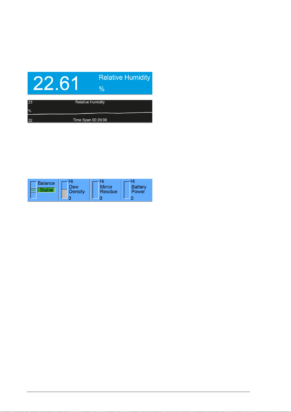
Data Lines
If numeric, a data line contains the value
to the left, with the parameter description
and units to the right.
If graphic, a data line shows a simple
graph of data over time.
Near the bottom of the display is the Status Line. The Status Line displays Bal-
ance, Density, Contamination, and,
optionally, Battery Power.
The first three lines of the display show a numeric or graphic representation of the measured data. We
will refer to these first three lines as Data Lines.
Data can be displayed in different parameters and units either numerically or graphically. Please refer
to section 4, ‘System Configuration’ to learn how to configure your preferences.
Status Line
Balance
Although it is directly obtained from the intensity of the mirror’s reflected light signal, balance is effectively the first derivative of the dew thickness measurement. It indicates the rate of growth or reduction
of the condensation layer on the mirror. While the dew or frost layer on the mirror surface is growing,
the indicator will be above center. The faster the layer is growing, the higher the indication. Conversely, when the layer on the mirror surface is evaporating, the indicator will be below center. The faster it
disappears, the lower the indication. When the indicator is in the center, the thickness of the dew or
frost layer is neither growing nor evaporating, and the layer on the mirror surface is in equilibrium with
the gas. In this center position of the indicator, there is no net exchange of water vapor between the
gas and the mirror surface. If the humidity of the gas sample is homogeneous and of low enough variability for the control system to sense a steady value, the Balance indicator will show a green Stable
message, accompanied by a few short beeps.
Density
The Density Indicator graphically depicts the approximate thickness of the dew or frost layer on the
mirror surface. The 473 can automatically differentiate between dew and frost layers and the indicator
will display the current condensation state. The label in the density indicator will change from Layer
Density (when the state of the layer is uncertain) to either Dew Density or Frost Density (when either dew or frost is being measured). For more information regarding Dew/Frost point determination
see section ‘Dew / Frost Control’ on page 20.
8 MBW473_MANUAL_E_V2.0
Page 13
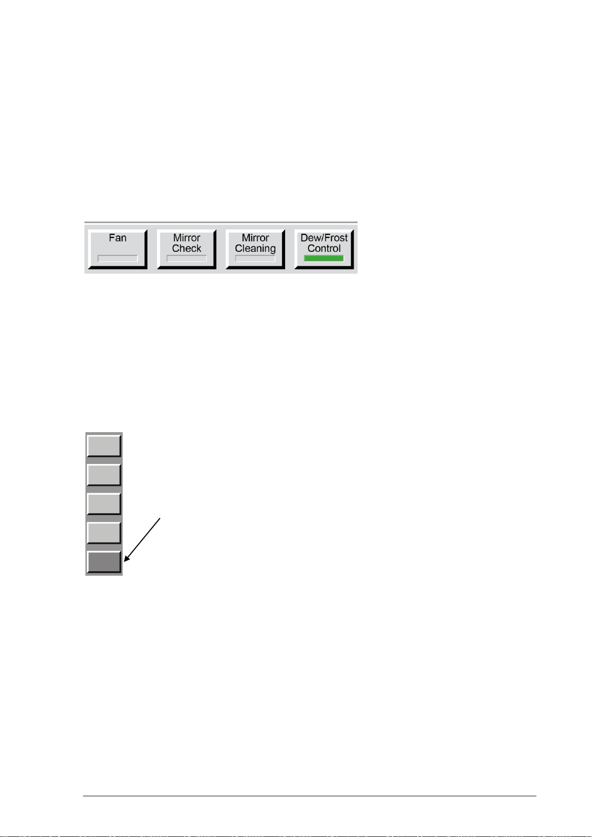
The bottom line of the display
contains a row of fixed function keys.
These keys are used to start and
stop the fan (only for SH2), initiate a
mirror check, initiate mirror cleaning,
and switch dew/frost control on or
off. For further infromation on the fan
see section 3.3, for the other
funcitons see section 4.5.
On the right hand side of the display there is a column of
menu keys. The bottom, dark gray key changes the current menu by cycling to the next menu. Each of the light
gray keys change their label and function based on the
menu that is currently selected.
Use the dark grey
Mirror Residue
The Mirror Residue Indicator graphically shows the amount of mirror contamination that was detected
during the last mirror check. If the bar covers more than a quarter of the space, we recommend that
you clean the mirror.
Fixed Function Keys
Menu Keys and Navigation
key on the bottom
(menu selection key)
to move between
menus.
The menu selection is circular. Once you go past the last menu, the first one will appears again and
the process starts over. You can use the ± key on the keypad to move backward through the menus.
Use the Enter key to exit the menu.
MBW473_MANUAL_E_V2.0 9
Page 14
3.2 Back Panel
Power Switch
The main power switch is on the back panel above the power plug. The power supply has a built-in
fuse and will automatically switch off in case of overload. To restart power, the main power switch
must be switched off and on again.
Power Plug
The supplied power cord is connected to the power socket on the instrument back panel. The supported power supply voltage is 100-120 VAC / 200-240 VAC at 50 to 60Hz. The power requirements
are specified on the serial number label on the back of the instrument.
RS-232
The RS-232 port can be used to connect the 473 to a desktop or laptop computer. The necessary 9pin RS-232 (serial) extender cable is a common accessory and can easily be obtained at any computer store.
10 MBW473_MANUAL_E_V2.0
Page 15

Optional Analog Outputs
The 473 can be ordered with two optional analog outputs which are independently configurable. For
each of the analog outputs, you can choose which parameter to track and how to scale the selected
parameter to the analog output range. Please refer to section 4.7 ‘Analog Output Connections’ to learn
how to configure the analog outputs.
Internal Barometric Pressure Sensor
As an option you can order an internal barometric pressure sensor to measure ambient pressure. To
measure chamber pressure or to calibrate the sensor, connect a 3 mm Swagelok tube to the pressure
sensor port on the back panel.
Measuring Head Connection
The 473 can be ordered with two different types of measuring heads; the RP2 and the SH2. Both
measuring heads are connected to the back panel of the 473 with the supplied 19-pin measuring head
cable.
External Temperature Probe
The external temperature probe is used to measure the temperature of the environment that is being
tested. To obtain certain humidity parameters, such as %RH, an external temperature measurement is
necessary. External temperature measurements are not required for dew or frost point measurements.
The SH2 is supplied with a Ø2.1 x 100 mm PRT temperature probe. The probe can be con-
nected to the 473 in the following ways:
1. Use the supplied 4-pin 0.5 m cable to connect the probe to the measuring head.
2. Use the supplied 5-pin 3 m cable to connect the probe directly to the back panel of
the instrument.
The RP2 is supplied with a Ø3 x 30 mm PRT temperature probe. The probe can be connected
to the 473 in the following ways:
1. Plug the temperature probe directly into the connector on the top of the RP2
measuring head.
2. Use the supplied 4-pin 0.5 m cable to connect the probe to the measuring head.
3. Use the optional 5-pin 3 m cable (available from the manufacturer) to connect the
probe directly to the back panel of the instrument.
MBW473_MANUAL_E_V2.0 11
Page 16
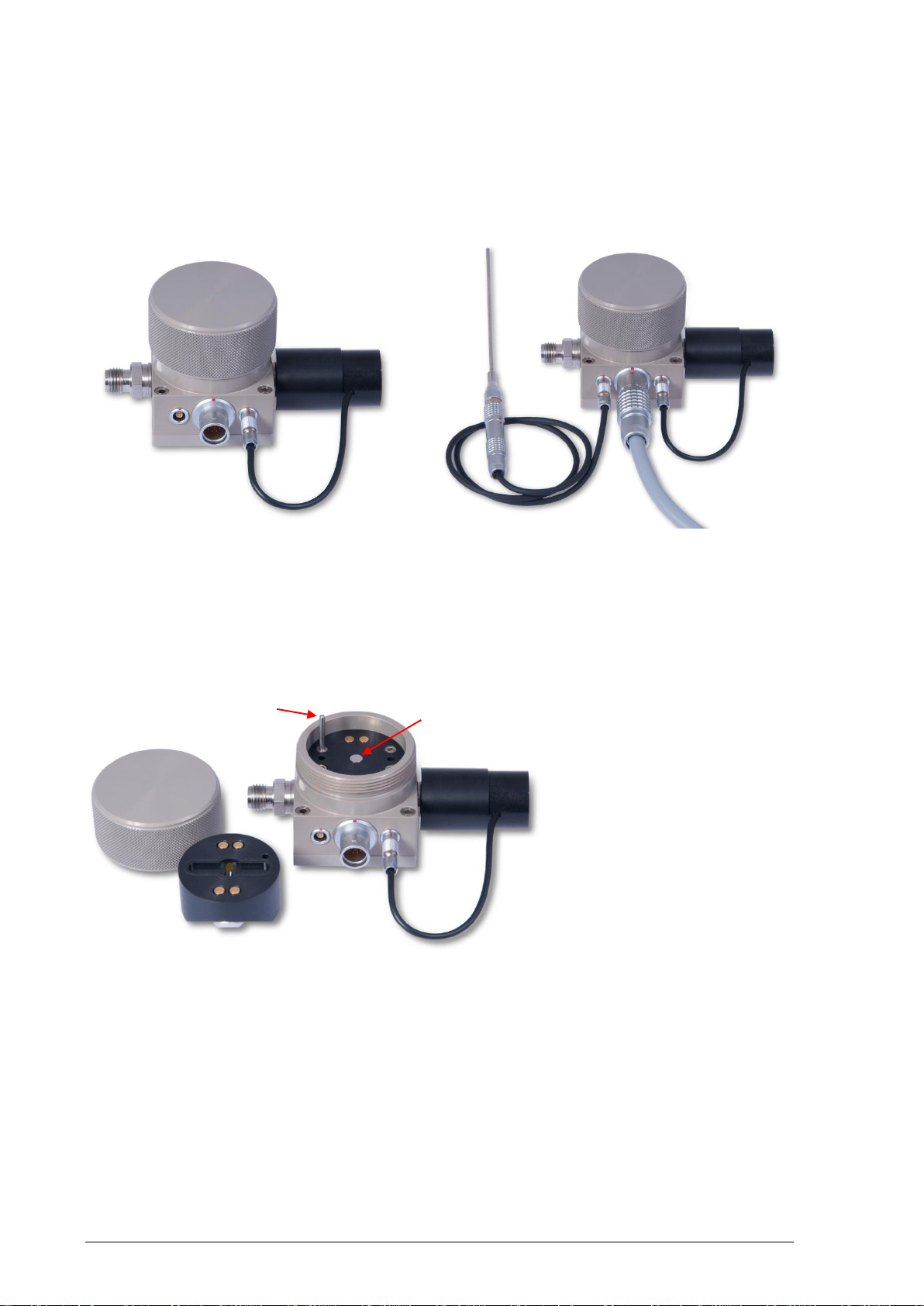
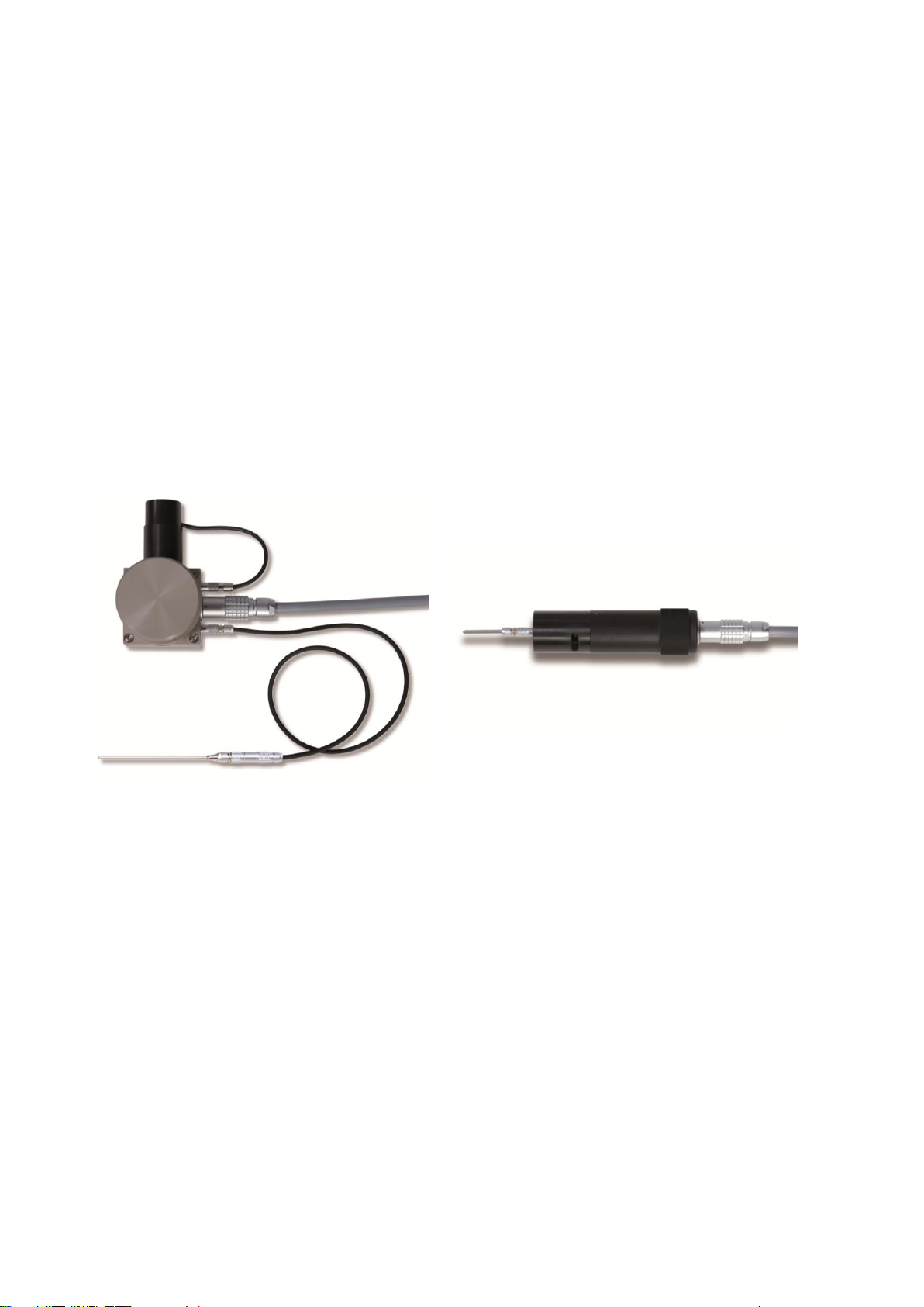
3.3 Measuring Heads
1. Gas Inlet
2. External Temperature Connection
3. 19-pin Measuring Head Cable Connection
4. Flow Fan
5. External Temperature Probe (Ø2.1 x 100 mm)
with 0.5 m Cable (4-pin)
6. 19-pin Measuring Head Cable (2 m)
7. Screw Cover
8. Measuring Head Front Part
9. Guide Pin
10. Polished mirror
1
2
3
4
5
6
7
8
9
10
The SH2 Measuring Head
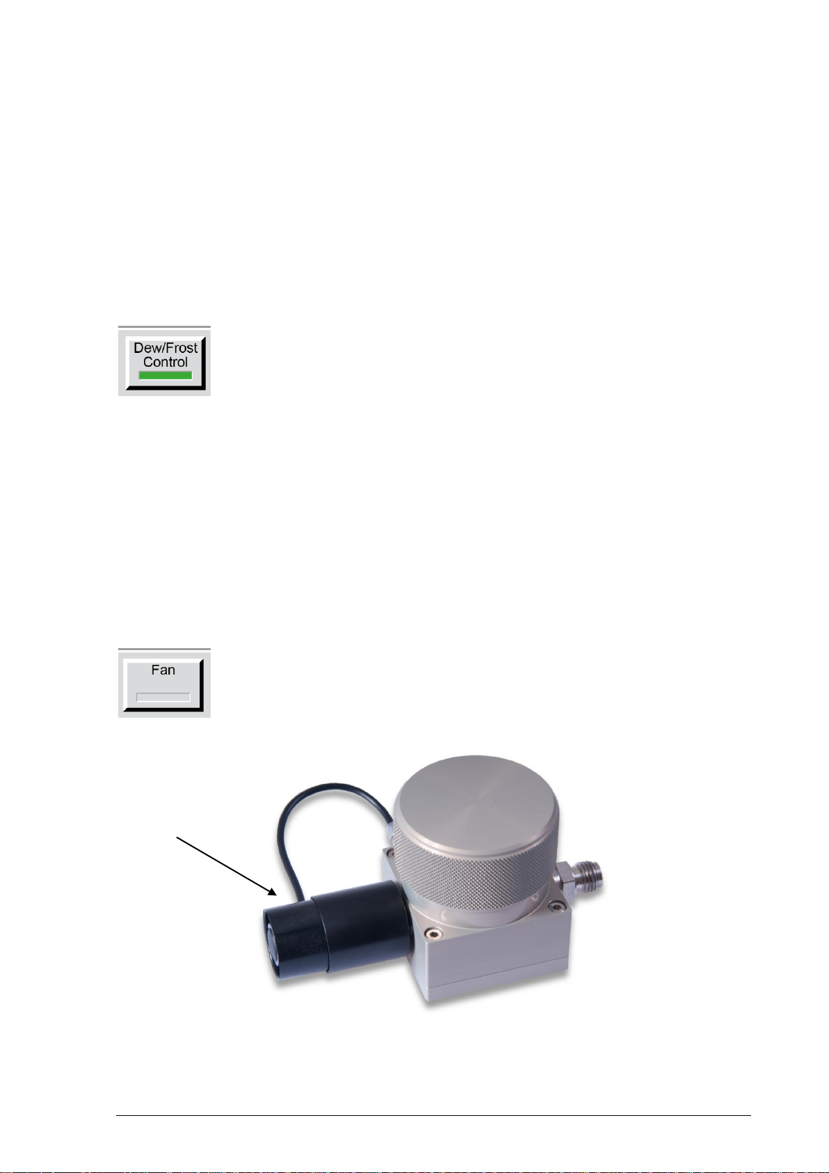
Fan
The fan of the SH2 measuring head is used to generate the necessary gas flow to the measuring
head, when no other gas flow is available. The fan can be removed and replaced with an output connector (Swagelok SS-6M0-1-2RS) for direct connection of gas tubing to other instruments.
12 MBW473_MANUAL_E_V2.0
Page 17

1. Temperature Probe Ø3 x 30 mm
2. Measuring Head Assembly
3. 19-pin Measuring Head Cable (2 m)
4. When reassembling the measuring head
take care to align the red marks.
5. External Temperature Connection
6. Polished Mirror
To adjust the position of the carrying handle, press the buttons on both sides. Release the buttons when the handle is in the
desired position. Ensure that the handle has
locked into place before lifting the instrument.
1 2 3
4
5
6
The RP2 Measuring Head
3.4 Carrying Handle
MBW473_MANUAL_E_V2.0 13
Page 18

14 MBW473_MANUAL_E_V2.0
Page 19

Parameter
This menu is used to select the parameters displayed on the data lines.
Numeric/Graphic
This menu is used to toggle a data line between numerical and graphic display.
Control Setup
This menu is used to configure the control functions like Dew/Frost Control or the Mirror Check.
Units
This menu is used to select the units in which you would like the data to be displayed. Unit
changes will be applied to all values displayed on the screen, such as temperatures, pressures
and concentrations.
Foreground Color
The menu Fore Color is used to temporarily change the color of the lines drawn on graphs
and the color of text (numbers and letters). The foreground color of each data line can be
changed individually. Unlike other settings, the color settings will be restored to the standard
color settings when the 473 is restarted.
Background Color
The menu Back Color is used to temporarily change the color of the background of the
numeric or graphic data lines. The background color of each data line can be changed individually. Unlike the other settings, the color settings will be restored to the standard color settings when the 473 is restarted.
4 System Configuration
Many aspects of the 473 can be configured depending on your measuring needs and preferences.
You can choose which humidity, temperature, and pressure values will be indicated on the screen,
their order and units, and whether each will be shown as a number or as a graph. In addition to the
display options, you can define how the 473 performs its control functions, such as Dew/Frost determination. Any changes in the configuration settings will remain active until the next time they are
changed. Color settings will be restored to the standard settings after restarting the instrument.
4.1 The Menu
The 473 has several menus to configure the system to meet your requirements. Use the dark gray
menu selection key to cycle through each of the menus. Each time you press the menu selection key,
the respective label will indicate which menu is currently active. Use the ± key on the keypad to move
backward through the menus.
Use the Enter key on the numerical keypad to exit the menus. This is not necessary, however, as
staying in a specific menu will not affect the measurement.
List of available menus:
MBW473_MANUAL_E_V2.0 15
Page 20

4.2 Selection of indicated Parameters
Parameter
Explanation
Dew Point
The temperature to which a gas must be cooled to start condensing water vapor to liquid water.
Dew point is pressure dependent and must be stated together with its associated pressure.
Frost Point
The temperature to which a gas must be cooled to start deposition of water vapor in the
form of ice. Frost point is pressure dependent and must be stated together with its associated pressure. Frost point exists only below 0 °C. While not technically correct, it has been
common industry practice to report values below 0 °C as dew point, although frost point is
the correct term. For further explanation on dew or frost point refer to ‘Dew / Frost Control’
in section 4.5.
%RH
The ratio between the amount of water vapor in a sample and the maximum amount possible at that same temperature and pressure.
%RH WMO
The ratio between the amount of water vapor in a sample and the maximum amount possible at that same temperature and pressure calculated using the World Meteorological Organization (WMO) formula.
Volume Ratio
The ratio between the water vapor volume and the total volume of the sample gas, generally expressed in parts per million by volume, ppmv or its numerical equivalent μl/l. Once
determined, ppmv has no further pressure dependence. It is also independent of the gas
type or mixture.
Weight Ratio
Weight ratio is the ratio between the mass of water vapor and the total mass of the sample
gas, generally expressed in parts per million by weight, ppmw or its numerical equivalent
mg/kg. Once determined, ppmw has no further pressure dependence, but depends on the
gas type and mixture through the molecular weight of the constituents.
Absolute Humidity
The weight of water vapor per unit volume of humidified gas.
Specific Humidity
A ratio of the water vapor to the total weight of the humidified gas.
Vapor Pressure
The partial pressure exerted by vapor in thermodynamic equilibrium with its condensed
phases (solid or liquid) at a given temperature. It is usually expressed in kPa.
Head Pressure
The pressure of the gas sample in the measuring head.
External Temp
The temperature measured by the external temperature probe.
Head Temp
The temperature measured by the PRT in the measuring head.
In the Parameter menu you can choose which parameters you would like to have displayed on the
data lines. When you select parameters for display on any of the four data lines, those selections remain valid until you change them again, even after you turn the 473 off. Below you will find the list of
the available parameters.
16 MBW473_MANUAL_E_V2.0
Page 21

Follow the steps below to choose the parameters you wish to have displayed on the four data lines:
1. Select the Parameter menu by
pressing the dark gray menu selection key until Parameter appears.
Small left pointing arrows will appear
on the four upper menu keys.
2. Press the arrow key next to the data
line you wish to change. Each time
you press the arrow key, the parameter of the respective line will change.
Continue pressing the arrow key until
the parameter you wish to view is
displayed.
3. Change the parameters on any of the
other data lines the same way.
4. If you choose the parameter External Temp, but have not connected the external temperature
sensor, no reading will be displayed. If you choose parameters that require the measuring head to
be connected, such as Frost Point, Dew Point, Head Temp, % RH, Humidity, Volume Ratio,
Weight Ratio, Vapor Pressure, or Head Pressure please make sure all the relevant equipment
is connected for the instrument to be able to display the chosen parameters.
4.3 Selection of Numeric or Graphic Data Display
Any data line may be viewed either in a numeric or a graphic format. The 473 automatically keeps a
short data history of every selectable parameter so that a graph appears instantly whenever a data
line is switched from numerical to a graphic mode. Use the Numeric/Graphic key to toggle any data
line between numerical or graphic mode.
1. Use the dark gray menu selection key to select the Parameter menu. Small left-pointing arrows
will appear on the four upper menu keys.
2. Press the arrow key next to the data line that you wish to change. The data line will toggle between numerical and graphic mode each time you press the key.
MBW473_MANUAL_E_V2.0 17
Page 22

4.4 Graph Scaling
Each graph can have its own x and y-axis scaling and range settings. There are three different scaling
modes to choose from; Autoscale Minimum (which is the default setting), Fixed Range or Mini-
mum/Maximum. Each of these is explained in more detail below. You can change the graph scaling
and switch between the three scaling modes at any time.
1. On the screen, touch the graph you
wish to change. A graph scaling dialog box will appear. One of the buttons in the Description column will
have a green indicator. This shows
you the currently selected mode.
2. If you would like to change the scaling mode, touch the button of the
mode you would like to select. Note
that for the Minimum/Maximum option, only the Maximum button needs
to be selected (the Minimum is then
automatically selected by the system).
3. Touch the corresponding field in the Change To column, next to the range that you have selected.
4. Using the numerical keypad, enter the value needed. If you make a mistake while entering the
value, touch the field you are editing on the screen. With each touch, the last digit in the field will
be erased.
5. Once you have entered the correct value, press the Ok button (or the enter key on the numeric keypad) to confirm. Press the Cancel button if you wish to abort all changes made in the dialog box.
Any values you enter will only be accepted by the system if they correspond with the
selected mode. If, for example, you enter a value into the bracket next to the
Autoscale Minimum, but Fixed Range is the selected mode, the Autoscale Minimum
value will remain unchanged.
Autoscale Minimum
The Autoscale Minimum mode is the default setting for this instrument. This mode sets the scaling
automatically so that all of the stored data will be visible on the graph at the best possible resolution.
As the range of the data changes, so will the range of the graph. In Autoscale Minimum mode, you
can select the minimum range that you want the graph to scale to. For viewing temperature and dew
or frost point graphs, setting the Autoscale Minimum to a value of 0.1 or greater is generally a good
choice. It allows the graph range to close in on the data as it stabilizes at a single value without the
range of the y-axis becoming too narrow.
For example, setting an Autoscale Minimum of 0.1 while the 473 is displaying a graph of a steady dew
point measurement of 20.0 °C will set the minimum and maximum value limits of the graph to 19.95 °C
and 20.05 °C, respectively. The graph will also zoom out as needed if a reading goes outside that
range. You can experiment with this value to determine your personal preference.
18 MBW473_MANUAL_E_V2.0
Page 23

Fixed Range
The Fixed Range mode allows you to select a fixed range for the graph’s y-axis. It automatically centers on the most recent data point. As the most recent data varies, so will the center point of the graph,
leaving the overall range fixed. The Fixed Range mode is mostly used to monitor data for stability. For
example, if you set the fixed range for the external temperature graph to 0.2 and the current data is
23.00 °C all data between 22.80 °C and 23.20 °C is visible on the graph.
Minimum/Maximum
In the Minimum/Maximum mode you can specify the minimum and maximum values used for the
graph’s y-axis. Unlike the other modes, the visible range of the graph’s y-axis will not automatically
change if a data point is outside the set minimum/maximum range. If the data points are outside the
specified range, you will not see them on the graph.
Time Span
Time Span determines the number of minutes of the data history that is visible on the graph. The 473
stores a fixed number of data points independent of the selected time span. Thus, changing the time
span will change the time interval at which the data points are stored. The total number of stored data
points will not change. With a time span of 15 (15 minutes), the graph data is sampled and stored
every few seconds. With a time span of 120 (2 hours), the graph data is only sampled, stored, and
updated about once a minute.
When you change the time span, the data that was sampled and stored at the old interval will be incrementally replaced by new data sampled at the new interval. The time span indicated on the graph
will always reflect the actual time span of the data that is displayed on the graph, and will agree with
the time span you selected once enough data points have been sampled. The selected time span is
common to all graphs, so they will always have the same time relationship to one another.
The time span can be changed in the Numeric/Graphic menu:
1. Touch the graph you wish to change on the screen. The Graph Scaling dialog box will appear.
2. Touch the Change To: field next to Time Span. The field will turn white.
3. Use the numerical keypad to enter an even value between 2 and 1440. As you enter the value it
will appear in the white Change To: field of the dialog box.
4. If you make an entry error, touch the field that holds the number you wish to change. Each time
you touch the field, the last digit entered will be deleted.
5. Press the OK button in the dialog box or press Enter on the key board to confirm the new value.
Press Cancel to leave it unchanged.
6. The result will take some time to show as the old data at the old time interval will be replaced by
data at the new time interval gradually as determined by your selected time span.
If you prefer to see the same measurement as both numerical value and graph, you may
select the same parameter on two data lines, and set one line to graph mode and the
other to numeric mode. See sections 4.2 and 4.3 for instructions on selecting displayed
parameters and changing their display modes.
MBW473_MANUAL_E_V2.0 19
Page 24

4.5 Control Setup
Using the Control Setup menu enables you to control the manner in which the 473 operates.
Dew / Frost Control
When measuring dew/frost points between 0 °C and -20 °C, condensation on the instrument’s chilled
mirror may be in the form of dew, frost, or a combination of both. If the state of the condensation is
not known, it will introduce errors into all the humidity measurements reported by the instrument.
To eliminate this potential source of error, the Force Frost function is used to rapidly cool the mirror to
below -20 °C, forcing all dew on the mirror into frost. The mirror will then re-stabilize at the frost point
temperature. Once the condensate layer is in a state of frost, it will remain frost for all sub-zero mirror
temperatures, allowing the instrument to measure the frost point accurately. The dew point and all
other humidity measurements are then mathematically calculated from the frost point.
To change the Force Frost settings:
1. Select the Control Setup menu by pressing the dark gray menu selection key until Control Setup appears.
2. Touch the Dew/Frost Control button.
The Mirror Dew/Frost Control window
will open.
3. The Force Frost function can be enabled or disabled by clicking on the Force Frost Below button.
If the indicator on the left side of the button is green, Force Frost is enabled. If the indicator is
grey, Force Frost is disabled.
4. To adjust the temperature below which Force Frost activates, click on the Change To: field to the
right of the Force Frost Below button. The field will turn white.
5. Enter the temperature in degrees C below which Force Frost should activate.
6. If you make an entry error, touch the field that holds the number you wish to change. Each time
you touch the field, the last digit entered will be deleted.
Press the OK button in the dialog box or press Enter on the keyboard to confirm the new value. Press
Cancel to leave it unchanged.
20 MBW473_MANUAL_E_V2.0
Page 25

Why it is Important to Distinguish Between Dew and Frost
For mirror temperatures above 0 °C, water vapor always condenses on the mirror in
its liquid phase (dew). A condensation layer on a mirror above 0°C is therefore always considered a dew point.
Although ice always starts melting at exactly 0 °C, water will not necessarily freeze at 0 °C. Water may
stay in its liquid phase at temperatures far below 0 °C. This phenomenon is referred to as ‘Super-
Cooled Water’.
The fact that water at subzero temperatures can condense either as dew or as frost makes it somewhat difficult to determine whether the condensate layer on the mirror at temperatures below 0 °C is
liquid or solid. Various factors such as contaminants, time, pressure etc. may cause the condensate
layer to remain liquid at mirror temperatures of –20 °C and below.
It is furthermore important to understand that the difference in the
temperature at which the liquid or the solid condensate layer stabilizes can be up to 3 ˚C. As shown on the picture to the right, it is
also possible that dew and frost exist concurrently on the mirror
which results in a non-stable value reading somewhere between
the dew and frost point.
Therefore the phase of the condensate must be known in order to
avoid significant errors and to correctly calculate all humidity values, including vapor pressure, dew point, %RH, volume ratio,
weight ratio, absolute humidity and specific humidity.
It would be desirable for manufacturers and users of humidity instruments to use the term frost point
for temperatures below zero and dew point for temperatures above zero. While not technically correct,
it has been common practice to use dew point for temperatures below 0 °C, although frost point would
be the correct term. As discussed above, dew point can exist below 0 °C in the form of super-cooled
water and is different in value from the equivalent frost point temperature. For the same vapor pressure, the frost point is approximately 10% of reading above the corresponding dew point value (when
expressed in °C). For example, a vapor pressure of 38 Pa corresponds to a frost point of −30 °C and a
dew point of −33 °C. From a measuring perspective it seems obvious that a clear and consistent dis-
tinction between dew and frost point is important.
MBW473_MANUAL_E_V2.0 21
Page 26

Mirror Cleaning
Activating the Mirror Cleaning function with the respective key at the bottom of the screen will heat the
mirror to a pre-specified temperature, getting the measuring head ready for the removal of the cover
and the optical assembly. If the mirror and other internal measuring head components are disassembled while they are cold and become exposed to normal atmospheric air, the possibility of undesired
condensation exists. Warming the mirror and other internal components to a safe head removal temperature, greater than or equal to the current ambient temperature, will prevent the formation of dew
on the mirror assembly during servicing.
To set the Minimum Mirror Temperature when activating the Mirror Cleaning mode:
1. Select the Control Setup menu by
pressing the dark gray menu selection
key until Control Setup appears.
2. Touch the Mirror Cleaning menu button.
3. Touch the Change To: field to the right
of the Minimum Mirror Temp label.
4. Enter the temperature in degrees C which the mirror must warm to during the Mirror Cleaning
mode,. It is recommended that you enter your current ambient temperature or higher.
5. If you make an entry error, touch the field that holds the number you wish to change. Each time
you touch the field, the last digit entered will be deleted.
6. Press the OK button in the dialog box or press Enter on the keyboard to confirm the new value.
Press Cancel to leave it unchanged.
Mirror Check
Mirror Check is the process of warming the mirror to evaporate all condensation, looking for the presence of contamination and accounting for it if necessary, then initiating a new dew or frost point measurement. Mirror Check may be started manually with the fixed Mirror Check key, or if enabled, it will
start automatically at pre-specified time intervals.
During a mirror check, whether triggered automatically or manually, the indicator on the fixed Mirror
Check key has the following meanings:
Red: The mirror is heating.
Brown: The mirror is holding at the programmed Mirror Check Temperature.
Yellow: The mirror is cooling to re-form the dew or frost layer.
Gray: The mirror check function is not currently active.
Once the system has re-established a dew or frost layer and become stable, the mirror check function
is completed and the color indicator turns gray.
After the Mirror Check is completed the bar of the Mirror Residue Indicator shows the amount of contamination on the mirror. If the bar covers more than a quarter of the space, we recommend that you
clean the mirror. For instructions on mirror cleaning, please refer to section 7.3 ’Mirror Cleaning’.
22 MBW473_MANUAL_E_V2.0
Page 27

Automatic Mirror Check
To view or edit the Mirror Check parameters, press the Mirror Check key of the Control Setup menu.
If automatic mirror checks are desired, select it by pressing the Cycle Time button. A
green light on the button indicates that automatic mirror check is enabled.
When the automatic mirror check is enabled, the Mirror Check key at the bottom
of the screen shows a countdown timer indicating the time before the next automatic mirror check is performed. In the automatic mode, the mirror check may
still be initiated manually by pressing the Mirror Check button.
Cycle Time
The Cycle Time is the number of minutes between automatic mirror check operations. Use the numerical keypad to enter the desired cycle time in minutes.
Heating Time
The Heating Time determines how long the mirror check temperature will be held before allowing the
next dew or frost point measurement. A heating time of 0 means that the instrument will resume dew
or frost point measurement immediately upon reaching the mirror check temperature. If a heating time
greater than 0 is entered, the mirror will heat and remain at that temperature for the chosen duration.
Heating time is effective regardless of whether mirror check is triggered automatically or manually.
Temperature
Edit the Temperature field to change the temperature, in degrees C, that the mirror will be heated to,
and optionally held at during Mirror Check.
If you have entered a wrong value into a field and want to erase it, press the entry field to
backspace.
MBW473_MANUAL_E_V2.0 23
Page 28

4.6 Selection of Units
Temperature Units
°C, °F or K
Pressure Units
Pa, hPa, MPa, atm, bar, mb, inHg, mmHg,
cmHg, inH2O, mmH2O, cmH2O, Torr or psia
Flow Rate Units
l/min, ml/min, l/h, cfm, or cfh
Weight Ratio Units
PPMW (Parts Per Million by Weight) or
PPBW (Parts Per Billion by Weight)
Absolute Humidity Units
g/l, g/m3, or lb/ft3
Specific Humidity Units
g/g, g/kg, or lb/lb
Vapor Pressure Units
Pa, hPa, kPa, MPa, atm, bar, mb, inHg,
mmHg, cmHg, inH2O, mmH2O, cmH2O,
Torr, or psia
You can display system data in any of a wide variety of units. When you change units, your selection
will remain until you change it again. Unit selections are global, which means that all values of that
parameter type across the whole system will change to the chosen units. For example, changing the
temperature units to °C will display all temperature data in °C.
Data retrieved via RS-232 will always be in SI units regardless of the units chosen for
display. Also note that settings within dialog boxes used for changing system parameters
are entered and displayed in SI units. Units only affect the four data lines.
Available units are:
24 MBW473_MANUAL_E_V2.0
Page 29

The 473 requires a 4-pin LEMO connector (www.lemo.ch).
Part Number: FGG 1B 304 CLAD 42.
Voltage
[V]
Current
[mA]
+10
20 2 4 0 0
-10
N/A
Pin
Signal
Position
Description
1
+V
When viewing the solder tubs of a
disassembled 4-pin LEMO connector,
pin 1 is usually identified with a full or
partial circle drawn around it. Pin 4
should have no identifier. When wiring
the cable, note that the pin numbering
of the socket in the back panel of the
instrument starts at the top left (pin 1)
and goes counter-clockwise (as
viewed from the rear of the unit).
2
-V
3
+I
4
-I
The red dot is between pin 1 and 4.
4.7 Analog Output Connections
The 473 can be ordered with two optional analog outputs which are independently configurable.
If the instrument is ordered with the optional analog outputs, a 4-pin LEMO connector will be supplied
with the instrument, which can be used to fabricate a custom cable for your application.
When the 4-pin LEMO connector is properly assembled, the red dot of the connector housing should
be between pin 1 and 4.
The 473 allows both a voltage and a current output signal. As shown in the illustration above, pins 1 and
2 supply the voltage signal (V), and pins 3 and 4 supply the current signal (I). Inside the instrument, the
output signal is connected to a D/A converter and then split into a voltage and a current signal. Therefore
you may use either a volt or current meter to receive the analog signal. The maximum voltage output
range is -10…+10 V. See the following table to identify the corresponding current signal.
MBW473_MANUAL_E_V2.0 25
Page 30

Configuration of Optional Analog Outputs
Parameter
Units
Enter
this #
Dew Point
[°C]
0
Frost Point
[°C]
1
RH
[%]
2
RH WMO
[%]
3
Volume Ratio
[PPMv]
4
Weight Ratio
[PPMw]
5
Absolute Humidity
[g/m3]
6
Specific Humidity
[g/kg]
7
Vapor Pressure
[Pa]
8
Head Pressure
[Pa abs]
9
Flow Rate
[l/min]
10
External Temperature
[°C]
11
Head Temperature
[°C]
12
For each of the analog outputs, you may select which parameter to track and how to scale the selected parameter to the analog output range. These selections are made for each of the analog outputs
via the Analog Outputs menu.
1. Access the Analog Outputs menu with
the menu selection key.
2. To make the selections for the first analog
output, press the Analog Output 1 key.
3. Use the numerical keypad to enter the
desired values. For details on each option, read the three following subsections.
4. Follow the same procedure for the second or any subsequent analog outputs
as needed.
Selection of Parameter to Track
In the analog configuration window, enter the number which corresponds to the parameter you wish to
track. Use the following table to identify which number to enter into the Parameter field. For example if
you wish to track the external temperature, enter number 11 into the entry field next to Parameter.
26 MBW473_MANUAL_E_V2.0
Page 31

Scaling the Output Signal
Use Min Value and Max Value to set the range of the Parameter, and use Min Voltage and Max
Voltage to set the range of the analog output signal.
Example 1
1. You want to track the parameter %RH
as an analog voltage output. The previous table shows that the parameter
%RH has been allocated number 2. Enter number 2 into the field next to Pa-
rameter.
2. The next step is to define the range of
%RH which will be covered with the analog output signal. You want to have the
whole range of 0…100%. Enter 0 into
the field next to Min Value and 100 into
the field next to Max Value.
3. Then, set the scaling of the analog output signal. You want to have 0…1 VDC on the analog output to represent the 0…100 %RH. Enter 0 into the field next to the Min Voltage and 1 into the field
next to Max Voltage.
Example 2
To keep things simple, we will take the
same Parameter, Min Value and Max
Value settings as in the first example.
However, this time you want the analog
output range to be scaled to mA instead of
volts. Your selected range is 4…20 mA for
the parameter range of 0…100 %RH. In
order to enter this into the system, please
refer to the table on page 26 to find the
voltage which corresponds to your desired
mA output range. You will find that 2…10 V
corresponds to 4…20 mA. Thus, enter 2
into the field next to Min Voltage and 10
into the field next to Max Voltage.
Calibration Adjustment
D/A Cal Gain and D/A Cal Zero are used to adjust the analog output signal accuracy. This adjustment
is made at the factory and will rarely need to be changed by the user.
MBW473_MANUAL_E_V2.0 27
Page 32

4.8 Selection of Color
1. Access the Fore Color menu. Fore
Color will appear on the dark gray
menu key, and the keys above will
show left-pointing arrows. Note that
each of the upper keys correspond to
the data lines they point to.
2. Press the arrow key of the data line
you wish to change. Note that the
foreground color of the data line will
change with each touch of the key.
3. Change the foreground color on any
of the other data lines the same way.
1. Access the Back Color menu. Back
Color will appear on the dark gray
menu key, and the keys above will
show left-pointing arrows. Note that
each of the upper keys correspond to
the data lines they point to.
2. Press the arrow key of the data line
you wish to change. Note that the
background color of the data line will
change with each touch of the key.
3. Change the background color on any
of the other data lines in the same
way.
The foreground and/or background color of any data line can be changed in the Fore Color and Back
Color menus. Access the Fore Color and Back Color menus with the menu selection key. To revert
to the default color scheme, press and hold key number 9 on the keypad for a few seconds until the
instrument beeps.
Foreground Color
The foreground color is the color of the numbers and letters. To change a data line’s foreground color:
Background Color
To change a data line’s back color:
28 MBW473_MANUAL_E_V2.0
Page 33

5 Set Up and Operation
5.1 Measurement Set Up
Back Panel Connections
The following picture shows the back panel of a fully connected 473 with RS-232 cable, 19-pin measuring head cable, power cable and the Ø2.1 x 100 mm PRT on the 3 m cable.
MBW473_MANUAL_E_V2.0 29
Page 34

5.2 External Temperature
Set Fixed External Temperature
If you do not use an external temperature sensor, you have the possibility to enter a fixed
external temperature. Set the parameter so that
External Temp shows on one data line (see
section 4.2). If no temperature sensor is installed, the data line will not show any reading.
Touch the External Temp data line on the
screen. A window (see picture below) will appear where you can enter the desired temperature.
Enter the desired temperature in degrees C
(21 °C in this example) and activate the Use
Fixed Ext Temp option by touching the button.
When the indicator square turns green, the
fixed external temperature is active.
The External Temp data line (and the graph, if
shown) will now say “(fixed)”. As shown in the
image on the right, the external temperature will
immediately change to the temperature that
was entered, and will remain there until it is
changed again.
If you want to start using an external temperature probe, go to the Fixed External Tempera-
ture window and press the Use Fixed Ext
Temp to disable the fixed external temperature
function. The green square will turn grey.
30 MBW473_MANUAL_E_V2.0
Page 35

If you wish to make your own thermometer cable, the 473 requires a 5 pin LEMO connector (www.lemo.ch), part number FGG
1B 305 CLAD 42.
Pin
Signal
Position
Description
1
Shield
When viewing the solder tubs of a
disassembled 5-pin LEMO connector,
pin 1 is usually identified with a full or
partial circle drawn around it. Pin 5
should have no identifier. When wiring
the cable, note that the pin numbering
of the socket in the back panel of the
instrument starts at the top left (pin 1)
and goes counter-clockwise (as
viewed from the rear of the unit).
2
+I
3
+V
4
-I
5
-V
Red Dot aligns with Pin 1
Use your own External Temperature Sensor
The External Temperature plug on the back panel is used for the connection of an external temperature probe. External temperature measurements are required if certain humidity parameters, such as
%RH, are to be computed. External temperature measurements are not required for dew or frost point
measurements.
After identifying pin 1, follow the line counter-clockwise from pin 1 to all other pins in succession. Wire
the cable according to the following scheme:
When the 5-pin LEMO connector is properly assembled, the red dot of the connector housing
is located directly above pin 1.
MBW473_MANUAL_E_V2.0 31
Page 36

5.3 Application Integration
The 473 is suitable for many applications over the humidity and temperature ranges detailed in Section 8 ‘Specifications’. When installing the measuring head into a system, the operating temperature of
the measuring head and the mirror cooling capacity must be carefully considered. A high measuring
head temperature will limit the lowest frost/dew point that can be reached; from a head temperature of
20 °C, the mirror cooling capacity is approximately 50 °C. This means that the lowest frost point with a
head temperature of 20 °C will be approximately -30 °C. If the mirror cooling is at its maximum capacity but cannot cool the mirror to at least a few degrees below the dew/frost point, the dew point or head
temperature will display a constant value above the actual dew/frost point and the Dew Density on the
status line will remain at 0 (zero).
Since the principle of dew point measurement requires the mirror to be cooled to a temperature where
condensation forms, the transfer of heat is important in order to attain the best measurement capability. If the body of the measuring head is in contact with other surfaces, these may cause additional
heating or cooling which are either useful or detrimental to measurement performance, so always take
time to consider the thermal properties of the measuring head and any items in its environment and
their possible effects.
The following application examples are included to show some of the most common applications of
the 473. In all cases, temperature effects are discussed and there may be similar implications in your
system.
Climatic Chamber Validation
A widely used method for validating or calibrating the working volume of a climatic chamber is to use a
chilled mirror to measure dew point temperature of the chamber environment. In combination with
single or multiple point temperature measurement, %RH values can be derived. Multiple temperature
measurement in a chamber is often referred to as ‘mapping’, and this method is described in
IEC 60068.
The 473-SH2 is well suited for this application. The SH2 measuring head can be positioned anywhere
within the chamber’s working volume, either
on a chamber shelf or directly attached to the
chamber surface. Direct surface contact between the base of the measuring head and the
chamber surface can be beneficial for improving heat transfer from the measuring head.
Heat transfer tape or paste can be used to
further improve thermal contact.
Adequate airflow through the SH2 measuring
head is important in order to provide stable
and repeatable measurements. The integrated
fan in the SH2 measuring head can be used to
provide the needed airflow through the measuring head. If necessary for your application,
an extension sample tube can be added using
6mm or ¼” Swagelok fittings as shown.
32 MBW473_MANUAL_E_V2.0
Page 37

At equilibrium, the water vapor pressure is assumed to be homogenous, but the user should determine this by experimentation according to the type of chamber being tested.Temperature
probes should be positoned according to the need for validation.
The most common arrangement is four probes in the top
corners, four in the bottom corners and a single probe in the
center. For larger chambers, more probes can be added so that
the entire working volume is measured. This allows for the full
spatial volume to be temperature mapped. By combining this
temperature data with the measured dew point, %RH can also
be mapped. Software such as that supplied with the MBW T12
temperature system can be used to display and record the dew point, temperature and calculated
%RH values. Please contact MBW or your local supplier for more information.
RH Generator Validation
Transportable RH Generators provide a convenient and fast
way of calibrating RH instruments. Most use RH sensor control probes to measure and control the conditions in the generator’s test chamber. The standard calibration uncertainty of
the RH generator is limited by calibration drift, linearity and
temperature coefficients of the control probe. With the use of
a dew point mirror, with its inherent stability and precision,
the uncertainty can be significantly improved.
The 473-RP2 is ideal for this application. As shown, the RP2
measuring head is introduced into the generator chamber
through a front access port. The measuring cell of the mirror
is exposed to the moving air within the chamber and measures the temperature and humidity of the
air as it passes over the measuring head. As with climatic chambers, it is assumed that, at equilibrium,
water vapour pressure is homogenous throughout the chamber volume. Provided that the temperature
is stable and uniform, the %RH derived from the dew point and temperature measurement is suitable
for use as a transfer standard for calibration of the generator’s control probe or as a reference against
which units under test can be compared.
Temperature Effects
Most RH generators are also able to control
temperature. This means that RH probes can be
calibrated for temperature at the same time as %RH.
The RH calibration can be performed at working
temperature. As RH is highly temperature dependent,
temperature effects and gradients, in particular, must be
considered. With the RP2 probe installed into the RH
generator chamber, the Peltier element that is used to
cool the mirror causes heat to be dissipated from the
body of the measuring head. This can cause
temperature gradients within the generator chamber.
MBW473_MANUAL_E_V2.0 33
Page 38

The user must therefore determine this effect experimentally for the conditions used. In the example
installation shown above, the RP2 measuring head and the chamber door are thermally coupled to
allow for optimum dissipation of heat generated by the measuring head. At equlibrium, the generator
will establish a thermal equilibrium within the complete system so that temperature stability is
optimized and gradients are minimized.
Whereas the RP2 head-mounted temperature probe (PRT) can be used for the measurement of
temperature in most measurement situations, in some chamber conditions a short extension cable
may be advisable to thermally ‘decouple’ the PRT from the measuring head. . Especially at low RH
conditions, where the mirror temperature can be much lower than the chamber temperature, the
heating of the measuring head can cause appreciable temperature errors . Therefore, consideration of
this possible effect must be included within uncertainty budgets. In calibration laboratories where the
lowest possible uncertainties are required, the implementation of continuous multi-point temperature
measurement allows the user to determine gradients dynamically. In such small chambers, four or six
PRTs arranged around the working volume is sufficient according to IEC 60068.
Condensation
If the RP2 probe is installed through the chamber ports of an RH generator working at high temperature, a thermal gradient through the RP2 may result and the probe may be at a slightly lower temperature than the chamber. This may cause condensation to form on the outer body of the RP2 probe. As
a result, the measured dew point values will be incorrect. It is even possible that condensation on the
head will cause a short circuit. To avoid such problems, make sure that the RP2 probe is inserted as
far as possible into the chamber volume. More advanced RH generators feature heated doors which
prevent condensation.
Working or Transfer Standard
In the calibration laboratory or workshop, the 473 provides the best possible measurement capability
for a working standard in RH generators. By using the 473 for continuous dew point and temperature
reference measurement, users can achieve small uncertainties and calibrate multiple probes in short
time periods.
When an RH generator is used for on-site calibration, the combination of the RH generator, dew point
mirror and temperature measurement system may not be practical for site engineers as they need to
run calibrations quickly to minimize down-time. Examples of this situation include calibration of instruments used in pharmaceutical production rooms, laboratories, and critical industrial processes. In this
case, the RH generator can be periodically validated using the 473 as a reference standard.
The user should define a working procedure to manage calibration traceability. Maintaining careful
calibration records and history for both the transfer standard and the generator is essential to properly
determine the calibration stability and drift components of uncertainty budgets. For further support,
please contact MBW or your local distributor.
34 MBW473_MANUAL_E_V2.0
Page 39

Signal
473
(9 pin)
Direction
Computer
(9 pin)
Computer
(25 pin)
1 1 8
*TxD
2 2
3
*RxD
3 3
2
DSR
4 4
20
*GND
5
5
7
DTR
6 6
6
CTS
7 7
4
RTS
8 8 5 9 9 22
6 Remote Communication
The 473 is equipped with a bidirectional RS-232 communications interface which allows connection to
a computer. This section provides the necessary information for the use of the interface, including the
hardware connections, communications settings, and the command syntax.
6.1 Hardware Connection and Cabling
Connect a computer to the 473 using a standard RS-232 9-pin extender cable. The extender cable
has a male connector on one end and a female connector on the other. If your computer has a 25-pin
serial port connector rather than a 9-pin connector, you will also need a 25-pin to 9-pin port adapter.
Both the 9-pin RS-232 extender cable and the 25-pin to 9-pin port adapter are commonly available at
most computer hardware dealers.
The 473 ignores the DSR and CTS handshaking signals. While there is no harm in connecting all 9
pins, the 473 only requires connection of three of the pins (pins 2=TxD, 3=RxD and 5=GND). For your
reference, the complete connector pin-out is listed in the following table. Note that the signals identified by * are required, while the others are optional.
* Denotes a required connection. All others are optional.
MBW473_MANUAL_E_V2.0 35
Page 40

6.2 Communication Settings
Baud Rate:
9600
Data Bits:
8
Stop Bits:
1
Handshaking:
None
To communicate with the 473, set your computer to the following configuration:
6.3 Command Syntax
This section details the general syntax guidelines regarding termination, leading and trailing spaces,
case sensitivity, and numeric values. Throughout this section, characters originating from the computer will be shown for illustrative purposes in this font. Characters originating from the 473 will be
shown in this font.
General Use
All commands require a question mark to indicate you are requesting data. When requesting data from
the 473, follow the command with ?, the question mark character. For example, the following requests
the current pump status.
Pump.on?
The 473 will reply with the current pump status (1 = on, 0 = off).
Termination Characters
All commands must be terminated with either a carriage return
nation
CRL
.
F
Regardless of the command sent, the 473 will reply with a carriage return linefeed
the response, provided the command is recognized as valid. Here is an example:
C
DP?
(sent by the computer to the 473)
R
-10.015
CRL
(sent by the 473 back to the computer)
F
If the command is unrecognized, the 473 does not respond. See example below.
Abcdef?
C
(invalid command sent from the computer)
R
C
or a carriage return linefeed combi-
R
CRL
at the end of
F
(no response from the 473)
36 MBW473_MANUAL_E_V2.0
Page 41

Parameter
Units via RS-232
Temperature
°C
Pressure
Pa
Flow
l/m
Volume Ratio
PPMv
Weight Ratio
PPMw
Leading and Trailing Spaces
The 473 ignores leading and trailing spaces. It also ignores spaces before and after equal signs and
question marks. For example, both the following commands are perfectly valid.
Dp?
Dp ?
C
R
C
R
However, the following command is invalid since spaces are embedded within the keywords.
D p?
C
R
Case Sensitivity
All commands are insensitive to case. For example, the commands DP?, Dp?, dP?, and dp? will trigger identical responses from the 473. They will return the measured dew point value.
Numerical Values
All numerical data received from the 473 is either in standard or in scientific notation. Receiving a
number as 12.34 is the same as receiving it as 1234e-2 or as 1.234e1. Depending on the value of
numerical responses the 473 sends out, it may send the numbers in either standard or scientific notation.
Numeric data is never appended with text of any kind. When requesting a temperature related value,
only the numeric portion of the value is sent. The units are assumed.
The following table lists the units of the numerical data that the 473 returns, regardless of the units
selected on the touch screen display or set via the RS-232. When you change units (even if you
change them via RS-232), you affect only what is seen on the display. All numerical values retrieved
from the RS-232 will always be in the following units.
MBW473_MANUAL_E_V2.0 37
Page 42

6.4 Command Reference
Syntax
Function
DP?
Dew Point, °C
FP?
Frost Point, °C
RH?
Relative Humidity, %
RHw?
Relative Humidity (WMO), %
PPMv?
Volume Ratio, PPMv
PPMw?
Weight Ratio, PPMw
AH?
Absolute Humidity, g/m3
SH?
Specific Humidity, g/kg
VP?
Vapor Pressure, Pa
P?
Head Pressure, Pa
Tx?
External Temperature, °C
Tm?
Mirror Temperature, °C
Th?
Head Temperature, °C
Om?
Mirror PRT Resistance, Ohms
Ox?
External PRT Resistance, Ohms
Syntax
Function
ID?
Returns a string containing instrument identification, i.e. DPM 473
IDN?
Returns only numeric portion of identifier, i.e. 473
Below you will find a list with all available commands grouped by function. All commands are considered read-only values.
Measurement Data
System Identification
38 MBW473_MANUAL_E_V2.0
Page 43

With the tip of your finger, press the center of the
yellow key in the upper right-hand corner of the
touch screen. The key will turn grey and another
key will turn yellow.
Now touch the yellow key in the lower left-hand
corner of the touch screen. The key will turn grey
and you have successfully calibrated the touch
screen.
Test your new touch screen calibration by pressing
the bottom right menu selection key several times.
If it does not work to your satisfaction, repeat the
calibration.
7 Maintenance
7.1 Calibrate the Touch Screen
Before using the instrument for the first time, or when the instrument is used by different operators,
you may need to calibrate the touch screen to your finger positioning preference. Left and right handed people, for example, may have different points of pressure when using the touch screen.
To calibrate the touch screen:
Press and hold the Enter key on the numerical keypad for 3 to 4 seconds. You will hear two short
beeps and the key in the upper right corner will turn yellow.
MBW473_MANUAL_E_V2.0 39
Page 44

7.2 Ice Test
Press the menu selection key on the lower right to select the
Units menu. Then press the Ice Test button.
Please note that the Ice Test will start immediately
after the Ice Test button has been pressed.
During the Ice Test, the mirror rapidly cools to approximately
-30 °C. Because the measuring head is open, humidity from
the ambient air starts to condense on the mirror. This forms
a frost layer on the mirror which can be facilitated if necessary by blowing on it. After reaching the low temperature and
forming ice on its surface, the mirror begins to heat. As the
temperature approaches 0 °C, the instrument will beep increasingly rapidly as the mirror gets closer to the ice-melting
temperature.
Watch the mirror closely. As soon as the mirror temperature
reaches 0 °C, the ice will melt into liquid water drops (phase
transition).
The measuring accuracy can be checked with a simple, built-in test. The test may be performed at any
time, and is recommended whenever the results of your normal measurements do not correspond to
expectations, and you suspect that there may be an error with the instrument.
The mirror must be visible to perform the Ice Test. If you have an SH2 measuring head,
remove the measuring head cover prior to the Ice Test as described in section 7.3 ’Mirror
Cleaning’. If you have an RP2 measuring head, disassembly is not necessary as the mirror is visible from the outside.
The Ice Test cannot be started as long as a dew/frost point measurement is in progress.
Make sure that the bar on the Dew/Frost Control key is grey.
40 MBW473_MANUAL_E_V2.0
Page 45

When you observe the phase transition on the mirror, press
the Ok button. The mirror temperature is measured at that
moment and a dialog box appears with the test results.
If the measured ice-melt temperature was in the range of ±
0.2 °C, the check is successful and will be indicated with the
calibration status PASS.
If the measured ice-melt temperature was outside the range
of ± 0.2 °C, the check was not successful and will be indicated with the calibration status FAIL. In this case the ice test
should be repeated. If it continues to fail, the instrument
should be sent to the manufacturer or an authorized agent
for evaluation and/or repair.
Press the Ok button on the PASS/FAIL status window.
The next window requests that you clean the mirror.
Clean and reassemble the measuring head as described in
section 7.3 ’
Mirror Cleaning’.
MBW473_MANUAL_E_V2.0 41
Page 46

7.3 Mirror Cleaning
To access the mirror and the opto-electronic components, remove the measuring head cover.
The cover looks like a large, tan-colored knurled knob.
To remove it, simply turn it counterclockwise. It requires approximately three full turns to completely
unscrew it.
Once the screw cover has been removed, remove the
black optical assembly (optical head) by pulling it
straight towards you. The loose half is the optical assembly containing the light emitting and light sensing
opto-electronic elements and the gold contacts. The
other half contains the mirror, temperature sensor, and
some mating gold contacts. Avoid touching the mirror
and gold contacts with your fingers to prevent contamination.
Clean the mirror with a clean cotton swab or a lint free
tissue.
Never attempt to polish the mirror.
If necessary clean the mirror with metha-
nol or alcohol. Then clean the mirror with
distilled water to ensure the cleaning
chemicals are completely removed from
the mirror surface.
At the heart of the 473 is the measuring head assembly. It is highly sensitive and accurate, yet easily
accessible for periodic mirror cleaning. To ensure high accuracy, the mirror should be cleaned before
starting a measurement. Inspect the mirror carefully. Use a magnifying glass, if necessary. If there are
signs of contamination or if you suspect that contamination is present, use the following procedure to
clean the mirror.
SH2 Measuring Head
42 MBW473_MANUAL_E_V2.0
Page 47

To access the mirror and the opto-electronic
components, remove the optical assembly from
the measuring head. The two red dots indicate
where the measuring head and optical assembly will separate. When reassembling the
measuring head after cleaning make sure the
two red dots align as shown in the picture.
To remove the optical assembly, pull the two
halves of the measuring head apart. The loose
half is the optical assembly containing the light
emitting and light sensing opto-electronic elements and gold contacts. The other half contains the mirror, temperature sensor, and some
mating gold contacts. Avoid touching the mirror
and gold contacts with your fingers to prevent
contamination.
Clean the mirror with a clean cotton swab or a
lint free tissue.
Never attempt to polish the mirror.
If necessary clean the mirror with
methanol or alcohol. Then clean
the mirror with distilled water to
ensure the cleaning chemicals are completely
removed from the mirror surface.
RP2 Measuring Head
7.4 Exterior Cleaning
Front Panel
The 473 front panel is completely sealed and can easily be cleaned with liquid glass cleaner or other
mild cleaning chemicals applied to a cloth. Clean the front panel periodically as needed.
MBW473_MANUAL_E_V2.0 43
Page 48

7.5 System Information
When you press the System Info button in the
Analog Outputs Menu a window appears which
gives you information about the model of the instrument, the version of the software and the serial
number of the instrument.
44 MBW473_MANUAL_E_V2.0
Page 49

Specifications
473-RP2
473-SH2
Measuring Ranges
Frost/Dew Point
Relative humidity
Temperature (head mount PRT)
Temperature (cable mount PRT)
-20…70 °C
5…100 %RH
-20...80 °C
-50…100 °C
-30…70 °C
2…100 %RH
-20…80 °C
-50…100 °C
Accuracy
Frost/Dew point
Temperature
≤ ± 0.1 °C (-20…70 °C), ± 0.2 °C
≤ ± 0.1 °C
Reproducibility
Frost/Dew point
Temperature
≤ ± 0.05 °C
≤ ± 0.05 °C
Standard Features
Temperature probe
Digital I/O
Display
Thermoelectric mirror cooling
Mirror temperature sensor
Gas connections
Transport case
Power cable
Operating instructions
Calibration certificate
RP2: Ø3 x 30 mm PRT, 0.5 m cable
SH2: Ø2.1 x 100 mm PRT, 0.5 and 3 m cables
RS-232
5.7” LCD with color touch screen
2-stage with typically 50 °C depression at 20 °C ambient
Platinum Resistance Thermometer (Pt100)
6 mm or ¼” Swagelok (SH2 only)
Custom fit foam-lined Peli 1550
2.5 m
English
Factory calibration: 5 points FP/DP, 3 points temperature
Upgrade to SCS accredited ISO17025 calibration available
Optional
Int. barometric pressure sensor
Analog outputs
0.1% or 0.01% accuracy, 700…1200 mbar
User programmable, 2x 4…20 mA or 0…10 V
Additional Information
Power supply
Operating conditions:
Instrument
Measuring heads
Storage conditions
100…120 VAC / 200…240 VAC, 50/60 Hz, 100 Watt (auto switching)
0…40 °C, 90 %RH non-condensing
20…80 °C, 99 %RH non-condensing
-20...50 °C
Weight & Dimensions
Dimensions
Weight
Protection
Instrument
W310 x H155 x D265 mm
5 kg
IP54
In Transport Case
W510 x H220 x D450 mm
12 kg
IP65
We reserve the right to change design or technical data without notice.
8 Specifications
MBW473_MANUAL_E_V2.0 45
Page 50

46 MBW473_MANUAL_E_V2.0
Page 51

Side View
9 Drawings
MBW473_MANUAL_E_V2.0 47
Page 52

Front View
48 MBW473_MANUAL_E_V2.0
Page 53

Top View
MBW473_MANUAL_E_V2.0 49
 Loading...