

Page 1
Important measurement data
OverviewOverview
SoftwareSoftware
DatacenterDatacenter
Contract ModulesContract Modules
ServicesServices
DatasheetsDatasheets
AlarmingAlarming
HardwareHardware
Data securityData security
just a click away!
With the most
flexible continuous
Monitoring System
SaaS
50008E/2 018-12
1
Page 2

Rotronic Monitoring System
Watch the short Explain-it MovieWatch the short Explain-it Movie
RMS – ROTRONIC MONITORING SYSTEM
The Rotronic continuous Monitoring System allows users to monitor anything from anywhere using an on-premise or
cloud (SaaS) solution.
Strongly regulated applications
• Fridges
• Cold rooms
• Freezers
• Transport with dry ice
• Cryogenics with nitrogen tanks
• Blood banks
• Clean rooms
• Warehouses
Less regulated applications such as:
• Museums
• Archives
• Storage areas
• And much more...
Customize your own RMS Architecture
2
Page 3
Rotronic Monitoring System
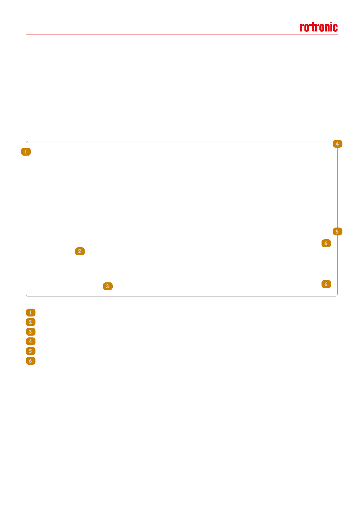
Multiple parameter monitoring
RMS monitors various parameters to ensure that the environment meets the required specifications for any application.
1. Digital probes give acces to a complete audit trail and easy digital calibration thanks to the probe hot swap possibility:
• Relative humidity
• Temperature
• CO
2
• Differential pressure
2. Other inputs and outputs for third party devices (particle counters, air flow and other such parameters):
• 0/4…20mA for the integration of existing devices or other parameters
• 0…10V for the integration of existing devices or other parameters
• Digital inputs for door contacts, leak detectors, etc.
• Digital outputs to switch alarm beacons
– Webcams to enable a snap shot to add to automatically generated reports and see the application
in real time (mouse-over)
mA
V
Real time camera view (mouse over)
– Any 3rd party devices with a documented protocol
– LoRa devices via the API function
3
Page 4

Rotronic Monitoring System
Find out more at www.rotronic.com/rmsFind out more at www.rotronic.com/rms
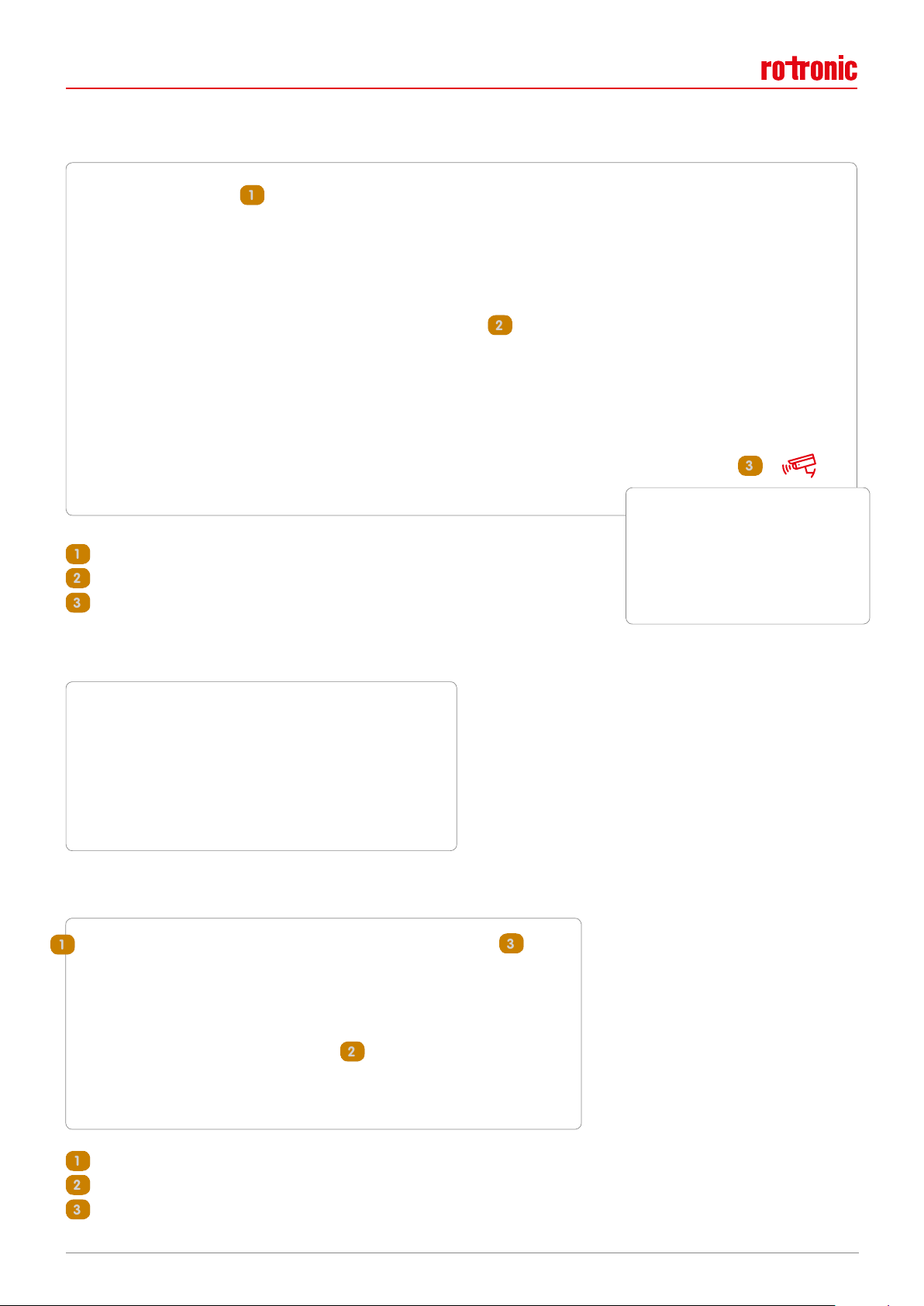
Wireless or wired secure data communication
1. Wireless:
• Data stored on the logger with a battery backup and 24V power supply
• Redundant or parallel operation with various gateways
• Decrease wiring costs
• No more looking for errors in cabling
• Projects accomplished faster due to no cable requirements
• Easy to relocated physical measuring points
• Fast and easy implementation of new measuring points
• Monitor mobile equipment
• 868 or 915 MHz
2. Wired:
• Data stored on the logger with a backup battery, PoE and 24V power supply
• No loss of communication for high risk applications
• Link up to the existing Ethernet network
Compliance
1. Validatable software (new releases on a 6 months basis)
2. FDA CFR 21 Part 11 compliant
3. EU Annex 11 compliant
4. Developed based upon the GAMP©5 recommendations
5. Complete GxP documentation and an IQ testing script (from the URS to the IQ/OQ/PQ)
Real time monitoring and alarming
The RMS software will inform you in real time via E-Mail, SMS and telephone call should a measurement point be out of
limits! Automatic reporting allow for a hassle free solution and a quick login via mobile phone, tablet, PC or laptop will
give you either a chart, table or a layout overview of the current situation, with short cuts to all events listed within the
audit trail.
4
Page 5

Rotronic Monitoring System
MONITORING SOFTWARE
Main Software Features
• Alarm overview – see directly how many alarms are active and where they are coming from
• Receive alerts via interactive phone, SMS’s and E-Mails
• Audit trail to see exactly what happened and when
• Monitor multiple locations – one system for all your monitoring locations
• Input floor plans – get a real overview of the setup
• Scalable – prefect for single points in small installations to thousands of points in worldwide installations
• Automatic report generation
• Integration of Rotronic and any third party hardware – analog and digital
• Automatic validation scripts – for fast and effective OQ validation
• Continuously developing based around customer feedback
• Create custom dashboards per user
• FDA 21 CFR Part 11 & EU Annex 11 complaint
• GAMP©5 conform for GxP applications
Additional Features
• Calibrate all of your measuring points, possibility to adjust all of the Rotronic devices
• Archive all measuring points that are no longer needed, keeping access to the data for as long as necessary
• Save all your documents in the system: user manuals, data sheets, calibration certificates, SOP’s...
5
Page 6

Rotronic Monitoring System
SaaS
SaaS
Main software benefits
• Compliance, audit and risk management
• Time saving with automatic data collection and report generation
• 24/7 real-time centralised monitoring of all operations
• All critical measurements in one system
• Real time alarming for critical measuring points
Software solutions
1. Fast & Easy with the Rotronic SaaS Cloud solution
Forget the hassle of having to maintain your IT infrastructure and focus only on what is crucial to your
application. You can setup multiple measurement points in various locations and access the data from
any device with a browser and internet connection. Setup alarms and notifications to be sure that you
are always informed of what is happening!
2. Remain compliant to GxP regulations with the Rotronic Exclusive SaaS Cloud solution
Hosted on a high security and redundant datacentre with your own virtual server, you can run the Rotronic category 4 software in the cloud throughout each and every GxP compliant facility. Equip your
worldwide facilities with the RMS hardware and access all of the data, including the audit trail, alarming and data analysis functions from a completely validated system.
3. Take advantage of your own IT infrastructure with the RMS on-premise solution
Hosted on a high security and redundant datacentre with your own virtual server, you can run the
Rotronic category 4 software in the cloud throughout each and every GxP compliant facility. Equip your
worldwide facilities with the RMS hardware and access all of the data, including the audit trail, alarming and data analysis functions from a completely validated system.
6
Page 7
Rotronic Monitoring System
11
22
33
445566
66
112233
44
55
66
System Overview
RMS offers different views/tabs to present your system data, customised to your needs.
• Chart – measured values graphically and numerically and direct notification status
• Table – measured values numerically and various other data
• Layout – measured values numerically with placement in a room layout
• Dashboard – individual dashboard for each and every user
• Events – audit logs, alarms, warnings and system messages
Chart view
Upload your company logo
Group information by location, room…
Real-time measurement value and live status
Current logged on user, and notification overview
Historical overview
Alarms bands for a visual depicture of warnings and alarms
7
Page 8
Rotronic Monitoring System
11
22
33
11
11
112222
22
33
33
33
Layout view
Real time camera view (mouse over)
Mouse over detailed measurement point
Standard measurement point overview
Mouse over IP camera for a snap shot of the current situation
Dashboard view: user defined
Events view (audit trail)
Define the notifications shown in the audit trail
See the actual status and user inputs of each individual event
Filter the audit trail based upon your requirements
8
Page 9

Rotronic Monitoring System
IT risk
certified
DATACENTER
RMS Database Security
When purchasing the RMS SaaS solution, Rotronic works together with the company 4Net. They provide a virtual data
centre for the Rotronic Monitoring System server and database. 4Net uses the Interxion data centre. Interxion’s Zurich
data centre provides an ultra-secure, known location for storing and processing data in line with Swiss data protection
regulations. Like all Interxion data centres, Zurich operates in full accordance with the ITILv3 framework and has ISO
27001 and ISO 22301 certification. Their compliance with the FINMA circular 07/8 is externally audited.
Operational excellence:
• 99.999% availability SLA
• 2N or N+1 configurations for all critical systems
• 24x7 operation and monitoring
Sustainability:
• 100% renewable energy
• Carbon neutral, certified by myclimate
®
Security:
• Monitored 24x7 by CCTV and security patrols
Resilience and business continuity:
• 24x7 monitoring and alarms for ever y critical system
• Connectivity: quadruple-entr y fibre from separate carrier main routes and rapidly installed cross connects
• Power: secured grid supply from two sub-stations from two different power providers, two power feeds for all
equipment, each independently equipped with a power supply and generator backup with full load capacity for
indefinite running
• Environment: SLAs on temperature and humidity in line with ASHRAE recommendations, N+1 cooling, sophisticated
water and very early smoke detection systems, Inergen® gas fire suppression in line with local regulations and
designed for maximum safety and minimum damage
• Backups saved in a second data centre also located in Switzerland but 80 km away from the main one
9
Page 10
Rotronic Monitoring System
ALARMING
Rotronic Monitoring System alarm protocols were set up to ensure that critical alarms cannot be missed. Notifications can
be triggered based upon the risk level.
Four levels of alarming are available, activation is based on the defined risk:
• Reminder for events that are non-urgent:
– Low battery (device)
– Simulator connected (measuring point)
– Reminder that a calibration is due
– Data gap after downloading missing measured values
• Warning for measured values that are out of limit (measuring point)
• Alarming for measured values that are out of limit (measuring point)
• Error for urgent hardware errors:
– Device timeout (device)
– Sensor error (measuring point)
An overview of the alarms can be seen once the user has logged into the system. The user only sees the alarms relevant
to his granted access rights. Each measuring point, if not conforming, will be attributed a different colour based upon the
alarm status:
Critical alarms can also be set up with a warning before alarms are activated. Hysteresis and a delay can be set up for the
warning, with upper and lower limits defined, as well as for the alarming.
All alarms are clearly shown in the audit trail indicating the unique ID for the event, the time and date of the alarm, information about what the alarm is, the target (the measuring point or device) as well as additional details.
Viewing the audit trail, it is easily possible to see if an alarm has been either acknowledged, or if it has ended. If an alarm
is acknowledged, the time, date, name of the user who acknowledged the alarm as well as the alarm details are also
saved and visible within the audit trail. Within the audit trail, it is also possible to close or inhibit an alarm.
10
Page 11

Rotronic Monitoring System
Alarms can be set up based upon either the measuring point, or via an alarm scheme. For alarms based upon the measuring point the choice of options is limited. Within an alarm scheme the user has the possibility to set a condition such
as an active time as well as a warning. An action can be configured in both situations.
The various alarms can be notified in different ways and can be sent to just one or multiple users.
• E-Mail
• SMS *
• Telephone call *
• Switch relay
• Send data via TCP
* The user’s telephone number must be added to the system.
E-Mail alarm: When setting the system up with a TCP/IP based camera, a snap-shot can be added to the E-Mail with a
chart (either as a PDF or included in the body of the E-Mail).
SMS alarm: The alarm will be sent out in the language in which the software is configured.
Telephone call: Within the system settings, the user can decide the information stated during the telephone call, from the
device/measuring point ID to a measuring point comment. For the telephone call, if various users are selected, the system
will call the first user on the list and continue through the list. Only when one user inhibits the alarm via the telephone will
calling stop. The inhibition time from the telephone call is also set up within the system settings.
Switch relay: If a device with a relay is included in the system, then with the alarm scheme, it is possible to trigger that
alarm to action either a visual or audible alarm, or another type.
Send data via TCP: Data can be transmitted to a TCP/IP device to switch a device to either On or Off.
It is also possible to set up IF-THEN scripts to trigger actions on the basis of one or more defined pre-conditions.
11
Page 12

Rotronic Monitoring System
HARDWARE
Lan and Wireless System
All RMS components are connected via a LAN or a wireless interface. All data is transmitted to the SQL database and
visualised via a web browser.
RMS Wall module
The RMS wall module is designed for applications where the module is visible to users:
simple and practicle. The module can be fixed
to the wall and easily wiped clean. The RMS
Wall module is available with either a LAN or
a wireless (868 or 915MHz) interface. The
module can be powered either via PoE (LAN
version only), 24V or battery and can store
44’000 data points.
Wall module devices:
• RMS-LOG-L / 868 / 915
• RMS-GW-868 / 915
The RMS Wall module also exists with display.
Wall module with display devices:
• RMS-D-L
The RMS Mini module
The RMS Mini module is only available with a
wireless interface (868 or 915MHz) and battery powered, with a storage of up to 12’000*
data points.
RMS Din Rail module
The RMS Din Rail module is for installation
where esthetiques are not crucial to the application. The RMS Din Rail module is available
with either a LAN or a wireless (868 or
915MHz) interface. The module can be powered either via PoE (LAN version only), 24V or
battery and can store 44’000 data points.
Din Rail module devices:
• RMS-DI-L-R
• RMS-DO-L-R
RMS Converter
The RMS Converter allows for integration of
digital third party devices with an Ethernet
connection. The converter will translate the
digital protocol and send it to the database,
the values are then visble via the web browser. The converter also has an onboard 7 day
memory** should the network go down. The
device is limited to 100 devices.
RMS converter:
• RMS-CONVERTER-100
Mini module devices:
• RMS-MLOG-T-868 / 915
• RMS-MLOG-T10-868 / 915
• RMS-MDI-868
• RMS-MLOG-B-868 / 915
• RMS-MADC-868-A / 915-A
• RMS-MADC-868-V
• RMS-MLOG-LGT-868
* Please check each device individually for the data storage possibilities.
** The converter should be on the same network as the third party device.
12
Page 13

Rotronic Monitoring System
DATA SECURITY / -INTEGRITY / FDA CONFORMITY
Data security, data integrity, data availability: these three terms play a central role in monitoring systems. The RMS
reassuringly scores in all these fields.
Data Security
Data security means the data cannot be accessed by unauthorized persons. This is achieved through encryption during
data transfer and storage.
Data Security in RMS
The monitoring system provides encryption of the data during transfer. This means the data can neither be tapped or
manipulated by so-called retry attacks. The security of the stored database in RMS is ensured by the IT structure. The
Rotronic Cloud is protected by certified IT data centers. If the database is located in the customer’s server center, the
customer defines the security infrastructure. Rotronic then offers IT support.
FDA/GMP Requirements
Regulators in the pharmaceutical and food industries demand that all relevant events are recorded so they are traceable.
This is achieved through the electronic marking of all calibration measurements and verification processes. The so-called
“electronic recording” requires unique identification of certificates. This means that every calibration certificate with a
date and inspection stamp must be traceable such that the calibration chain can be verified.
Audit Trail
When a monitoring system is commissioned, it is calibrated and validated. In this way the operator assures his Quality
department that the system works correctly. During subsequent operation, all relevant changes must be recorded in full.
The audit trail guarantees recording of all changes in the system such as, for example, change in measurement probes,
user activities, battery change. This in turn ensures that all events can be tracked at a later date.
Data Availability
For some manufacturar’s systems, data availability can contradict data security because secure data are difficult to access. The user must authenticate themselves and use secure connections or verified platforms. Nevertheless, the trend
is clearly moving towards worldwide data accessibility allowing platform-independent viewing and evaluation.
Data Integrity
Ensuring data integrity means guaranteeing secure transmission and storage. A measured value must not change during
transmission because of disruptions. Data transmission and storage must therefore be safe from manipulation. This is
achieved with CRC checksums and intermediate storage during data transmission. In this way, faulty data communication
is recognized and the data stored in the buffer memory are sent again until the transmission has been finished.
All data in RMS are sent with CRC checksums and confirmed by the recipient after receipt. Faulty data transmission is thus
ruled out. Should the data not arrive with the recipient, they are stored intermediately by the logger and can then be
transmitted at a later point in time when the connection has been restored.
13
Page 14

Rotronic Monitoring System
RMS Communications
14
Page 15

Rotronic Monitoring System
RMS SERVICES
Project Procedure
The Rotronic Monitoring System (RMS) is a hardware and software solution adjustable to your requirements for a continuous monitoring system. The complete system conforms to GAMP5, Rotronic is well aware that our support is crucial to
your project, so we offer a complete solution. From the user requirement specifications to the IQ/OP/PQ with our detailed
documentation finishing off with tailor made training for your employees.
Furthermore the RMS software is delivered as a GAMP software category 4 system.Our main goal is to fully understand
your requirements and deliver the best continuous monitoring system for you and your company.
Review of the URS
Rotronic has designed a functional description document explaining each and every function
of the RMS software. This description will help you create your own URS, but it might also
help you adapt the one you already have striving to provide the best risk based approach to
compliant GxP computerised systems. Don’t know exactly how to build up your URS? No need
to worry, Rotronic have the knowledge and documentation required to help support you in
any case.
The continuous monitoring system RMS is a very flexible solution both on the hardware and
the software side (R&D and production in the Headquarters in Switzerland). You have a problem, let us work together to give you the perfect solution. A personal discussion is of the
upmost importance though, only when speaking to you can we really understand your requirements for a continuous monitoring system!
Design Concept
After fully understanding your requirements, a project is setup at Rotronic. Each and every
step is listed, costs evaluated and an initial time line defined. A crucial point is software adaptations, any adaptions are follow a stringent testing process within Rotronic, so project
timing is a key to a successful roll out of your continuous monitoring project.
Rotronic has the possibility to carry out the complete monitoring system project, from the
heat mapping of the various areas to the physical installation of the devices. Internally, the
project team needs to understand your requirements in order to deliver your solution based
upon your time line. Our main aim is an optimised communication based upon information
transfer to the entire team: sales, product management, inside sales, after sales, production
and R&D are all involved already in this initial process.
Conceptual Offer
Rotronic will give you an initial quotation based upon your URS and the project planning. This
initial quotation is rarely the final quotation, but a ball park figure that will help you to get a
feeling for the costs of a project. Products will be added and removed, services will be adapted… The initial quotation will help you get a feel for the market and already an understanding
of what working with Rotronic is like. We are more than happy to invest time in a project, so
that you get the best continuous monitoring solution possible!
15
Page 16

Rotronic Monitoring System
On site Demo Installation
Pricing and promises in hand, we consider it important that customers actually tr y out the
RMS. Be it via our cloud solution or our server software, our engineering team will offer you a
solution based upon your requirements. When you start to play with the software, very quickly, thanks to its simple and effective design, you can work your way through the different
functions and get a real understanding for what the system can offer.
With just a few measurement points, you can already get a feeling for what is going on in the
various locations that you monitor. Increase of CO2, people are in the room, a temperature
decrease might mean that the heating has been cut off, the lux increase, the sun is coming
up… Everything of course can be verified by adding an IP camera next to the measurement
point to confirm what you are seeing.
You can get a feel for the alarming functions, an overview of how the audit trail actually works
and what data you can extract from the system! We will support for the optimal installation of
your demonstration, you need to test it to understand the flexibility of what Rotronic can offer
you. After seeing the demo, new ideas will appear and will help
Final Offer
You now understand that the sky is not the limit with our universal RMS. You’ve had new
ideas, seen new potential and have accordingly updated your URS. Rotronic has been with
you throughout this process and can now give you a tailor made quotation responding to your
exact detailed requirements for a continuous monitoring system.
Verification from the Customer
Of course, a market comparison is necessary! The flexibility and quality of RMS, the professionalism of our team and the complete package that we can offer will be sure to make Rotronic a very competitive partner for your project. Need more details from our side, don’t
hesitate to give us a call. Remember, we are FDA 21 CFR Part 11 and GAMP 5 conform for the
most demanding applications, but we can also help you with smaller projects where these
regulations are not required. With the Rotronic Monitoring System, we have a shoe that fits
every foot.
Installation /Commissioning
Congratulations on choosing to partner with Rotronic on your project! After a review of the
project planning and time lines, we can start with the physical installation of the devices, the
setup of the software and SQL database on your server, the configuration of the software and
the hardware (this is as well something that you can choose to do on your own, we are always
happy to offer a helping hand). The heat mapping or the wireless signal mapping can both be
carried out with the helping hand of Rotronic should this be a necessity.
16
Page 17

Rotronic Monitoring System
Validation
The software is validatable, so time to validate your continuous monitoring system. If you did
the URS with the Rotronic documentation, then we can also offer the rest of the validation
documentation, the validation master plan, the risk assessment, the functional requirement
specifications, the configuration specification, the requirement traceability matrix, the validation script specification, the installation qualification, the operation qualification and the
performance qualification of course followed by your tailor made training.
This validation model is based upon the GAMP5 standard and is recognised throughout the
pharmaceutical world. The entire validation will prove that your system replies to your URS.
Even if you didn’t use the Rotronic URS, you can still use the Rotronic documentation as
guidelines. With our team of trained professionals, Rotronic can carr y out the validation of
your system partially or fully if required.
Maintenance and Support
Who better to receive support from but from the manufacturer?
Maintaining your system is crucial for the running of your processes. Rotronic offers packages from ISO-17025 and ISO-9001 calibrations only (temperature, relative humidity, dew
point, differential pressure) to hardware and software maintenance contracts, build around
your requirements. The software is also setup in a way that it makes hardware changes ever
so simple and effective. Like the system our support is already very flexible!
17
Page 18

Rotronic Monitoring System
RMS CONTRACT MODULES
Create your tailored version based on the various modules
Software Hardware General Support Installation
Services
PURCHASE PURCHASE INCLUSIVE OPTIONAL OPTIONAL COMPULSARY
RENT PURCHASE INCLUSIVE OPTIONAL OPTIONAL INCLUSIVE
PURCHASE RENT INCLUSIVE OPTIONAL OPTIONAL COMPULSARY
RENT RENT INCLUSIVE OPTIONAL OPTIONAL INCLUSIVE
Onsite
Maintenance
Premium Support
What we can offer
SaaS
SaaS
Fast & Easy Software only Solution
Take advantage of our SaaS solution, freeing you from complex software and IT
hardware management and benefit from our outstanding IT infrastructure with
a state of the art security and data redundancy setup. You are guaranteed to
have a 99.01% availability of your data with no hidden costs! You will also benefit from free software improvements and upgrades throughout the lifetime of
your monitoring system.
Carefree Hardware Solution
You also have the possibility to also rent the hardware from us! Rotronic will keep an
inventory of relevant measurement product for you so that you do not have to manage anything other than returning the defective units to us. Should a product fail or
break, it will be replaced within 24 working hours1. No more issues with making
room in your warehouse, finding the devices when you need them and no more cash
tied up in possibly never used stock.
SaaS Software &
Contract
SaaS Software
Contract
Hardware
only
Carefree Installation Service
You and your team are too busy or you do not have access to qualified personnel. Your configurable environmental monitoring system can be setup to run,
exactly how you want it to as soon as the devices are delivered. Let us install
and configure your hardware and software; you will not have to lift a finger!
Carefree Maintenance SLA
Once your system is up and running, who better than Rotronic to service your
system. We can calibrate (ISO-17025 or traceable) your devices on a yearly basis, calibrations on site are also possible. At the same time change filters,
O-rings and make sure that hardware is running the latest firmware. To guarantee data redundancy, we can also change batteries and ensure that your system
is running smoothly.
1
For customers in Switzerland.
Overview
Service
SLA
Onsite
Maintenance
18
Page 19

Rotronic Monitoring System
Questions? Do not hesitate to contact us: rms@rotronic.chQuestions? Do not hesitate to contact us: rms@rotronic.ch
V
Fully Compliant Exclusive Contract
For GxP compliant systems that require validation, Rotronic offers a turnkey
solution from A to Z. Let us know what your user requirement specifications are
and let us provide you with the solution!
On-Premise Support
If you already have solid IT infrastructure in place, responding to your security
policies and up to date with the latest norms, we also offer all of the above with
an on-premise software solution.
Stay up to date premium Support
Stay up to date and improve your monitoring with the latest software updates
and features sent out to you on a regular basis.
Contract
Exclusive SaaS
Overview
Support
SLA
Premium Support
19
Page 20

Rotronic Monitoring System
RMS Data LoggerRMS Data Logger
RMS GatewayRMS Gateway
RMS Mini LoggerRMS Mini Logger
RMS ConverterRMS Converter
RMS-8ADC-L-R-ARMS-8ADC-L-R-A
RMS-PCD-S-XXXRMS-PCD-S-XXX
RMS-CCD-S-XXRMS-CCD-S-XX
RMS DisplayRMS Display
RMS-DI-L-RRMS-DI-L-R
RMS-DO-L-RRMS-DO-L-R
RMS-8ADC-L-R-VRMS-8ADC-L-R-V
RMS-4RTD-L-RRMS-4RTD-L-R
CF632-W-INC-20CF632-W-INC-20
AD-0001AD-0001
WB-0001WB-0001
RMS AccessoriesRMS Accessories
RMS-HCD-SRMS-HCD-S
DATA SHEETS
20
Page 21

www.rotronic.com
1
The Hygroclip Digital RMS-HCD was specif ically designed for use as part of the Rotronic Monitoring System (RMS). Building upon our experience we
improved the power consumption so that it is usable by battery powered system like the RMS wireless data loggers. Having less cabling reduces
installation cost and increases the flexibility of the installation.
Standard
Compatible with the following with RMS data loggers such as the RMS-LOG-L (LAN data logger), RMS-LOG-868 (Wireless and RMS-LOG-915.
• Application Range 0…100 %RH, -40…85 °C
• Accuracy ±0.8 %RH, ±0.1 K @ 23°C
• Factory-adjustment @ 23°C and 10, 35, 80 %RH
• Humidity Sensor HYGROMER HT-1
• Long-term stability < 1% RH /year
Industrie
Industry probes have a sensor head separated from the measurement electronic by a cable. This allows a higher application range for the sensor
head.
• Application Range sensor head 0…100 %RH, -100…190 °C
• Application Range electronic 0…100 %RH, -40…85 °C
• Accuracy ±0.8 %RH, ±0.1 K @ 23°C
• Factory-adjustment @ 23°C and 10, 35, 80 %RH
• Materials PPS, stainless steel 1.4301
• Humidity Sensor HYGROMER HT-1
• Long-term stability < 1% RH /year
Order Code Type
RMS-HCD-S Black Probe
RMS-HCD-S3 White Probe
Order Code Cable length
RMS-HCD-IC102 2 m
RMS-HCD-IC105 5 m
RMS- HCD-S RMS-HCD-IC102
RMS-HCD-IC105
59083E/2018-08
RMS-HCD
Advantages
• Measures relative humidity and temperature
• Outstanding accuracy, repeatability and long-term stability
• Advanced probe housing and construction
• Compatible with RMS data loggers and RMS Soft ware
• Low power
Applications
• Pharmaceutical Monitoring
• Food Monitoring
• Museum Monitoring
• Monitoring conform to GxP and FDA CFR PART 11
Page 22

Possible Filters
Order Code Filter carrier Filter Element Pore size Application Range
SPA-PCB-PE
SPA-PCB-PTFE PTFE, white
SPA-PCB-WM Wire mesh 1.4401
SPA-PCW-PE
SPA-PCW-PTFE PTFE, white
SPA-PCW-WM Wire mesh 1.4401
SPA-PE
SPA-PTFE PTFE, white 10 μm -100...200 °C
Polycarbonate, black
Polycarbonate, white
No filter carrier, only f ilter
Polyethylene, white 40-50 μm
10 μm
Polyethylene, white 40-50 μm
10 μm
Polyethylene 40-50 μm
-50 …100 °C
Possible Extension Cables
It is possible to extend the distance between the probe and its reading device with extension cable.
• Passive connection are possible up to 5m (see table below for possible options).
RMS-HCD probe
Ex-x xA Extension cable
Max imum 5 m
Reading Device
RMS-LOG-868
RMS-LOG-915
TECHNICAL INFORMATION
RMS-HCD-S, RMS-HCD-S3
108 mm Ø 15 mm
RMS-HCD-IC102, RMS-HCD-IC105
15O mm
111 mm
144 mm
RMS-LOG-L
Order Code Cable Leng th Color
E2-01A 1 m
BlackE2-02A 2 m
E2-05A 5 m
E3-01A 1 m
WhiteE3- 02A 2 m
E3-05A 5 m
Technical Data
Humidity sensor
Temperature sensor
Operating humidity
Operating temperature
Accuracy @ 23 °C
Supply voltage
Current consumption
Protection rating
Digital communication
Compatible devices
Compliance
HYGROMER HT-1
PT1000, Class 1/3 B (RMS-HCD-S)
PT100, Class 1/3 B (RMS-HCD-IC)
0…10 0 %RH
-40…+85 °C RMS-HCD-S
-40…+85 °C RMS-HCD-IC electronic
-100 …190 ° C RMS-HCD-IC sensor head
±0.8 %RH
±0.1 K
2.5…5.5 VDC
5 mA (RMS-HCD-S)
12 mA (RMS-HCD-IC)
IP65
UART
RMS-LOG-L
RMS-LOG-868
RMS-LOG-915
GAMP5
FDA 21 CFR Part 11
Subject to technical change without notice. Printing and other errors reserved.
2
www.rotronic.com
59083E/2018-08
Page 23

www.rotronic.com
1
The Rotronic dif ferential pressure probes are ideal for clean rooms, operating theaters and applications where even minor differences in pressure can
have a big effect. Thanks to our two different measurement methods (thermal mass flow measurement and diaphragm measurement), we offer the
perfect solution for every requirement. Together with other measurement parameters, these probes can be integrated in RMS per fectly.
Compatible with
• RMS-LOG: Wireless ≥V1.5/LAN data loggers ≥V1.4
Dimensions
59067E/2018-09
RMS-PCD-S-XXX
TECHNICAL INFORMATION
Advantages
• High-precision measurement and long-term stability
• With ambient pressure compensation
• Large overload range
• With flow or diaphragm sensor technology
• Compatible with RMS logger, RMS On-premises software
and SaaS solutions
Applications
• HVAC
• Cleanroom
Ø 32 mm
113 mm
197 mm
105 mm
87 mm
76 mm
Page 24

TECHNICAL INFORMATION
General specifications FDA & GAMP compatibility
Sensor type
Parameter
1
Accuracy
at 23 °C ±3 K
Long-term stability
3
Flow Membrane
Differential pressure
±1% F S ±1% FS
2
±0.1% FSS/year ±2% FSS/year for ±25Pa
probe
±1% FSS/year for ±50Pa
probe
±0.5% FSS/year for
±100 Pa probe
±0.25% FSS/year for
±250Pa und ±500Pa
probes
Zero point compensation
4
Automatic, 1x
per measure-
Manual, with external
tube; via R MS software
5
ment interval
Medium
Air Air & non-aggressive
gases
Ambient pressure
Automatic Not necessary
compensation
Adjustment and calibration
Factory adjustment/calibration:
5 points
Customer adjustment: max. 9 points
Measurement range
-25...+25 Pa / -50…+50 Pa / -100...+100 Pa /
-250...+250 Pa / -500…+500 Pa
Pressure resistance
5 bar 0.7 bar
(burst pressure)
Leak rate
Startup time
Measurement interval
<180 µl/min. 0 µl/min.
<0.5 s
1 s probe
≥10s RMS / 1s Modbus
Response time ττ 63
Range of application
<1 s
-20…+80°C (0…+70°C temp.-comp.)
0…95% RH non-condensing
Voltage
Current consumption
Battery life
RMS wireless logger
3.3 – 5.5 V
30 mA (avg.) 12 mA (avg.)
60d @ 10s
130d @ 10s interval
interval
350d @ 60s
650d @ 60s interval
interval
Battery life
LAN logger
70d @ 10s
interval
395d @ 60s
180d @ 10s interval
840d @ 60s inter val
interval
Protocols
1
Ple ase see the device ma nual for detaile d considerations .
2
For ma ximum accuracy, Rotronic recommends strongly to perform a zero point compensation
af ter the installat ion and initial op eration and to repe at it annually. For a ggressive enviro n ment s / gas media, a more f requent zero poi nt compensation i s advised. Plea se see the device
manual for detailed considerations.
3
Hi ghly reducible by a zer o point compensat ion of the RMS- PCD-S-Mx x (membrane sen sor).
4
A zero point adjustment is recommended for every installation or position change.
5
Ple ase see the device ma nual for detaile d considerations .
Modbus RTU
FDA / GAMP directives
Housing / Mechanical parts
Housing material
Fire protection class
Dimensions
Pressure connections
Weight
IP protection class
FDA CFR21 Par t 11 / GAMP5
Polycarbonate (housing)
Stainless steel DIN 1.4305
(nuts, connectors)
Corresponds to UL94-HB
Ø 32 mm x 87 mm
Tubing connector internal
Ø 4 mm x 10 mm
60 g
IP65
2
www.rotronic.com
59067E/2018-09 Subject to technical change without notice. Printing and other errors reserved.
Page 25

www.rotronic.com
The Rotronic CO2 probes are ideal for of fice rooms and applications whe-
re the quality of room air has a big effect. Together with other measure-
ment parameters, these probes can be integrated in RMS perfectly.
Compatible with
• RMS-LOG: Wireless ≥V1.5/LAN data loggers ≥V1.4
Dimensions
1
Acc uracy relates to the uncertainty of c alibration mix tures +- 1 %
59069E/20 18-09
RMS-CCD-S-XX
TECHNICAL INFORMATION
Subjec t to technical change wit hout notice. P rinting and ot her errors r eserved .
Advantages
• High-precision measurement and long-term stability
• With ambient pressure compensation
• Large measurement range
• With automatic CO2 calibration
• Compatible with RMS-Logger, RMS On-premises software
and SaaS solutions
Applications
• Open-Plan Offices
• Classrooms
• Shopping Centers
113 mm
186 mm
105 mm
76 mm
Ø 32 mm
Measurement principle
Infrared (NDIR)
Parameter
CO
2
concentration (ppm / %)
Accuracy @ 25 °C ±10 K,
20 – 60 %RH
(after min. 3 weeks ABC)
1
±50 ppm ±3 % of read value
@ 0 – 2000 ppm
±10 % of read value
@ 2000–10,000 ppm
Medium
Air & non-aggressive gases
Ambient pressure &
temperature compensation
Automatic (300 – 110 0hP a)
Adjustment and calibration
Factor y adjustment/calibration: 1 point
Customer adjustment: max. 9 points
Measurement range
0…2000ppm / 5000ppm / 10'000ppm
Resolution
1 ppm
Startup time
≤300s
Measurement interval
16s pro be
Response time ττ 63
130s @ level descending
87s @ level ascending
Range of application
0…50°C, 0…95%RH non-condensing
Voltage
3.3 – 5.5V
Current consumption
(16 s interval)
20 mA (avg.) / peak 260 mA
Battery life
(RMS wireless/LAN logger)
2.7d @ 10s/60s inter val
Interface
UART
Protocols
Modbus RTU
FDA / GAMP directives
FDA CFR21 Par t 11 / GAMP5
Housing material
Polycarbonate (housing)
Stainless steel DIN 1.4305 (nuts)
Fire protection class
Corresponds to UL94-V2
Dimensions
Ø 32mm x 87mm
Weight
55g
IP protection class
IP40
Page 26

www.rotronic.com
TECHNICAL INFORMATION
The data logger is the flexible component between the probe and the da-
tabase in the Rotronic Monitoring System. It stores 44,000 pairs of mea-
sured values from the interchangeable CO2, differential pressure, humid-
ity or low dew point probe, and transmits them to the RMS database via
LAN or wireless link. It guarantees absolute data protection, even if power
supply and communications should break down temporarily.
Compatible with:
• CCD-S CO2 probe
• PCD-S Differential pressure probe
• HCD-S Humidity and temperature probe
• RMS-GW Gateway
• RMS-WEB On-premises software
• RMS-CLD SaaS solutions
Dimensions
59057E/2018-04
RMS DATA LOGGER
General specifications
Measured parameters Humidity & temperature, CO
2
, differential
pressure, LDP
Range of application -40..70 °C / 0..100 %RH
Storage conditions -40..30 °C / 0..95 %RH
Maximum altitude 2000 m ASL
Power supply 24 VDC ±10 % / <100 mA / Bat tery: RMS-BAT
(2xAA , LiSocl2) / PoE: 802.3af-2003, Class 1
AC adapter requirements 24 VDC ±10 % / 4 W nominal /
<15 W power-limited
Battery life 3 years (at 23 °C, measurement inter val 1 min.,
HCD-S probe)
Device data
Measurement interval 10 s to 15 min.
Startup time < 10 s
Order code RMS-LOG-L RMS-LOG-868 RMS-LOG-915
Interfaces Ethernet ISM 868 MHz ISM 915 MHz
Indoor wireless
range
- 20..50 meters 15..25 meters
Protocols HTTP / MODBUS TCP
Ethernet cable
requirement
Min. Cat. 5, SFTP, max. 30 m
Conformity with standards
FDA / GA MP directives FDA CFR21 Par t 11 / GAMP 5
Housing / Mechanics
Housing material ABS
Fire protection class UL94 –V2
Dimensions 105 x 113 x 38 mm
IP protection class IP65
Weight 200 g
Subject to technical change without notice. Printing and other errors reserved.
Advantages
• 44,000 data point memor y
• Fail-safe, thanks to internal battery
• Wireless or LAN inter face
• Compatible with RMS Gateway, RMS Server Software and RMS Cloud
• Conforms to FDA CFR 21 Part 11 / GAMP 5
Applications
• Pharma monitoring
• Food monitoring
• Museum monitoring
105 mm
113 mm
38 mm
Page 27

www.rotronic.com
1
59059E/2018-12
mA
V
RMS MINI WIRELESS LOGGER
TECHNICAL INFORMATION
Advantages
• Saves up to 10,000 measured values
• Fail-safe thanks to internal battery and battery monitoring
• Battery life up to 3 years
• Conforms to FDA 21 CFR Part 11 / GAMP5
• ISM band 868 MHz / 915 MHz
Applications
• Environmental chambers
• Pharmaceutical industr y
• Analog third-part y devices
• Incubators
Compatible with
• RMS-GW-868: Firmware V1.0
• RMS-GW-915: Firmware V1.5
• Software V1.2: RMS-MLOG-T10-868
• Software V1.2.1: 915 MHz devices
Dimensions / Connections
Top view
Rubber cap (front view)
* with wall bracket
Wall bracket
General specifications
Device t ype RMS Mini Wireless Logger
Memor y size 10,000 measured values
13,000 data points (RMS-MLOG-B)
Range of application (elec-
tronics)
-30...85 °C / 0...100 %RH
-40…85 °C/0…100 %RH (RMS-MLOG -B)
Storage conditions -30...30 °C / 0...95 %RH
Battery RMS- BAT
Battery life 3 years (at 23 °C and 1 minute inter val)
2.7 years (RMS-MLOG-B)
Measurement interval 10 s to 15 min (software dependant)
Wireless interface ISM 868 MHz ISM 915 MHz
Indoor wireless range 20...50 meters 15...25 meters
Conformity with standards
FDA / GAMP directives FDA 21 CFR Par t 11 / GAMP5
Housing / Mechanics
Housing material ABS
Dimensions 83 x 29 x 29 mm
IP protection class IP65, IP30 (RMS-LOG-B)
Fire protection class UL94-V2
83 (87*) mm
29 (32*) mm
87.4 mm
65 mm
3.7 mm
7.5 m m
14 mm
Rubber cap
Grommet
Button
Status LED
26 mm
Page 28

www.rotronic.com
2
TECHNICAL INFORMATION
59059D/2018-12
Type Range / Accuracy
Temperature
& humidity
RMS-MLOG-B-868
RMS-MLOG-B-915
-40...85 °C (±0.5 °C @ 25 °C / ±1 °C @ 0...70 °C / ±3.5 °C @ rest of temperature range) /
0…100 %RH (±3 %RH @ 25 °C)
Temperature RMS-MLOG-T-868
RMS-MLOG-T-915
-30...85 °C (±0.4 °C @ 25 °C)
Details: see page 3
Temperature with
external probe (NTC)
Further NTC probes
available in various
lengths. Please con-
tact Rotronic.
RMS-MLOG-T10-868
RMS-MLOG-T10-915
Accessories
Item no.
T10-0001 T10-0002 T10-0003 T10-0004
Application
Cryotechnolog y Freezers,
dry ice...
Standard Cable duct
monitoring
Probe operating range
-196...-90 °C -80...200 °C -50...200 °C -50...200 °C
NTC accuracy
range
-196...-90 °C -80...150 °C -50...120 °C -50...120 °C
Dimensions /
Housing
Ø 6 x 50 mm / stainless steel
Cable length
2 m
Power input RMS-MADC-868-V (0...10 V)
RMS-MADC-868-A
RMS-MADC-915-A
(0...20 mA)
0...10 VDC ( ±0.1 V @ 25 °C)
0...20 mA or 4...20 mA (shunt 110 Ohm) ±0.2 mA @ 25 °C
Digital input RMS-MDI-868
Accessories
Item no.
DC-0001
Application
Door contact / magnetic trigger
Switch
Normally open
Cable length
30 cm
Mounting
M3 screws
IP
IP65
Illumination RMS-MLOG-LGT-868 T he RMS-MLOG-LGT detect s light, meaning that it is possible to monitor the difference bet ween dark
and light. The LUX measurement values are not precise and are only used for scaling. T he device is not
designed for an accurate LUX measurement.
mA
V
Page 29

TEMPERATURE ACCURACY
RMS-MLOG-T & T10 accuracy overview
The RMS-MLOG-T10-X XX allows users to implement their own NTC sensor. It is possible to add the NTC nominal value and B constant within the RMS
software. For NTC’s from Rotronic, simply choose the NTC from the dropdown list (as of Software V1.2).
The RMS-MLOG-T10-X XX can be calibrated and adjusted (2 points) via the RMS soft ware. When using external NTC’s, please account for the accuracy
of the RMS-MLOG electronics.
Accuracy overview
T10-0001*
Accuracy between -196...-90 °C ±2.5 °C
T10-0002*
Accurac y at 25 °C ±0.2 °C
Accurac y at -80...-30 °C ±1 °C
Accurac y at -30...40 °C ±0.5 °C
Accurac y at 40...70 °C ±1 °C
Accurac y at 70...200 °C ±3 °C
T10-0003* and T10-0004*
Accurac y at 25 °C ±0.4 °C
Accurac y at -50...0 °C ±1 °C
Accurac y at 0...30 °C ±0.5 °C
Accurac y at 30...60 °C ±1 °C
Accurac y at 60...90 °C ±1.5 °C
Accurac y at 90...200 °C ±3.2 °C
RMS-MLOG-T-XXX
Accurac y at 25 °C ±0.4 °C
Accurac y at -30...0 °C ±1.3 °C
Accurac y at 0...40 °C ±1 °C
Accurac y at 40...85 °C ±1.5 °C
RMS-MLOG-T10-XX X electronic measurement accuracy
Accurac y at 25 °C ±0.1 °C
Accurac y at -200...-40 °C ±0.4 °C
Accurac y at -40...150 °C ±0.3 °C
Accurac y at 150...200 °C ±0.6 °C
RMS-MLOG-T10-XXX electronic temperature accuracy
Accurac y at 25 °C ±0.0 °C
Accurac y at -30...85 °C ±0.3 °C
To calculate the total accuracy of the RMS-MLOG-T10-XX X, it is necessary to add all variables together.
* NTC accuracy
Examples at various temperatures
Use of the T10- 0002 at 25 °C and the RMS -MLOG-T10-XXX at 25 °C
T10-0002 accuracy at 25 °C ±0.2 °C
RMS-MLOG-T10-XXX electronic measurement accuracy
at 25 °C
RMS-MLOG-T10-XXX electronic temperature
accuracy at 25 °C
Total accuracy at 25 °C ±0.3 °C
Use of the T10- 0001 at -196 °C and the RMS-MLOG-T10-XX X at 25 °C
T10-0001 accuracy at -196 °C ±2.5 °C
RMS-MLOG-T10-XXX electronic measurement accuracy
at -196 °C
RMS-MLOG-T10-XXX electronic temperature
accuracy at 25 °C
Total accuracy with the sensor at -196 °C
and the logger at 25 °C
Use of the T10- 0003 at 35 °C and the RMS-MLOG-T10-XX X at 35 °C
T10-0003 accuracy at 35 °C ±1 °C
RMS-MLOG-T10-XXX electronic measurement accuracy
at 35 °C
RMS-MLOG-T10-XXX electronic temperature
accuracy at 35 °C
Total accuracy at 35 °C ±1.6 °C
Improvement in accuracy:
When using the data logger with the inter nal NTC or any of the NTC’s
provided by Rotronic, it is possible to carry out a 1 or 2 point adjustment
in order to improve the measurement accuracy.
1 point adjustment:
• Adjustment range: -25...125 °C
• Accuracy: ±0.3 °C
• Accuracy range: adjustment point ±10 °C
2 point adjustment:
• Adjustment range: -25...125 °C
• Accuracy: ±0.3 °C
• Maximum span of the 2 adjustment points: 80 °C
±0.1 °C
±0.0 °C
±0.4 °C
±0.0 °C
±2.9 °C
±0.3 °C
±0.3 °C
3
www.rotronic.com
59059D/2018-12
Page 30

www.rotronic.com
TECHNICAL INFORMATION
The gateway is the interface bet ween the wireless data logger and the
server sof tware. It can manage up to 60 data loggers simultaneously,
collecting all wireless-logger measurement data, and passing them on
to the ser ver software. When several gateways are used in the same net-
work, they are configured redundantly. If one gateway should fail, the
measurement values are automatically sent to the ser ver soft ware via
another gateway.
Compatible with:
• RMS LOG RMS data logger
• RMS MLOG RMS mini-logger
• RMS-WEB On-premises software
• RMS-CLD SaaS solutions
Dimensions
59058E/2018-03
RMS GATEWAY
General specifications
Range of application -40..70 °C, 0..100 %RH
Storage conditions -40..30 °C, 0..95 %RH
Maximum altitude 2000 m ASL
Power supply 24 VDC ±10 % / <100 mA / PoE: 802.3
af-2003, Class 1
AC adapter requirements 24 VDC ±10 % / 4 W nominal / <15 W
power-limited
Device data
Measurement interval 10 s to 15 min.
Startup time < 10 s
Order code RMS-GW-868 RMS-GW-915
Interfaces Ethernet &
ISM868 MHz
Ethernet &
ISM 915 MHz
Indoor wireless range 20..50 meters 15..25 meters
Protocols HTTP
Ethernet cable requirement Min. Cat. 5, SFT P, max. 30 m
Conformity with standards
FDA / GA MP directives FDA CFR21 Part 11 / GAMP 5
Housing / Mechanics
Housing material ABS
Fire protection class UL94 –V2
Dimensions 105 x 113 x 38 mm
IP protection class IP65
Weight 200 g
Subject to technical change without notice. Printing and other errors reserved.
Advantages
• Connects 60 wireless data loggers simultaneously
• 5 wireless channels for parallel and redundant operation
• Compatible with RMS Wireless Data Loggers, RMS Server Sof tware
and RMS Cloud
• Conforms to FDA CFR 21 Part 11 / GAMP 5
Applications
• Monitoring of mobile equipment
• Extensible applications
• For redundant requirements
105 mm
113 mm
38 mm
Page 31

www.rotronic.com
TECHNICAL INFORMATION
The LAN display is a freely configurable display. As a remote display, it
can be placed optimally where it suits the viewer best. It is able to show
the measured values, states and alarms of RMS products. The display
shows up to four measured values. Two measured values are shown at
a time. If more than 2 measured values have been selected, the display
alternates between the values that are to be displayed ever y 5 seconds.
Compatible with:
• All measuring points
• RMS-GW RMS Gateway
• RMS-WEB RMS On-premise
• RMS-CLD RMS SaaS
Dimensions
59070E/2018-01
RMS DISPLAY
105 mm
113 mm
38 mm
General specifications
Device t ype RMS Display
Display of measuring points Up to 4 measuring points
Range of application -20...70 °C / 0...100 %RH
Storage conditions -20...30 °C / 0...95 %RH
Power supply 24 VDC ±10 % / <100 mA / PoE: 802.3
af-2003, Class 1
AC adapter requirements 24 VDC ±10 % / >4 W / power-limited
Measurement interval 10 s
Interface Ethernet
Protocols HTTP
Conformity with standards
FDA / GA MP directives FDA CFR21 Part 11 / GAMP 5
Housing / Mechanical par ts
Housing material PC, ABS
Fire protection class UL94-V2
Dimensions 105 x 113 x 38 mm
Display diagonal 2.26 inch
IP protection class IP65
Weight 206 g
Subject to technical change without notice. Printing and other errors reserved.
Advantages
• Shows up to 4 measured values
• Automatic adjustment of backlight on alarm
• Compatible with RMS data loggers, RMS On-premise
and RMS SaaS
• Conforms to FDA CFR 21 Part 11 / GAMP 5
Applications
• Critical places
• Cleanrooms
Page 32

www.rotronic.com
TECHNICAL INFORMATION
The digital input module stores all measured data on an event basis and
sends it to the database via Ethernet. The minimum pulse time is 100
ms. Should the connection be lost, the module stores the data inter-
mediately to protect data integrit y and fills up the data gaps when the
connection has been restored. The device has a batter y so that logging
of measured data is also ensured in the event of a failure in the external
power supply.
Compatible with:
• RMS-Config
• RMS-WEB On-Premise
• RMS-CLD SaaS solutions
Dimensions
59071E/2018-01
RMS-DI-L-R
General specifications
Device t ype RMS-DI-L-R
Number of inputs 2 independent digital inputs
Range of application -40..70 °C / 0..100 %RH non-condensing
Storage conditions -40..30 °C / 0..95 %RH
Maximum altitude 2000 m ASL
Power supply 24 VDC ±10 % / <100 mA / PoE: 802.3
af-2003, Class 1
AC adapter requirements 24 VDC ±10 % / 4 W nominal /<15 W
power-limited
Battery type RMS-BAT
Battery life 3 years at 23 °C
Device data
Input frequency Max. 0.833 Hz or 1.2 s
Pulse recognition >100 ms (periodically > 1.2 s)
Input circuit Logic level: 0 V / 5-24 V
Trigger threshold: ~3.77 V
Current consumption: <1 mA
Reed circuit Max. load at input 100 k Ω
Max. cable leng th at input <3 m
Measurement interval Event-based & inter val (10 s to 15 min.)
Storage capacit y 75,000 data points
Interface Ethernet
Protocols HTTP
Conformity with standards
FDA / GA MP directives FDA CFR21 Part 11 / GAMP 5
Housing / Mechanical par ts
Housing material Polycarbonate (PC)
Fire protection class UL94-V0
Dimensions 89.7 x 62.2 x 108 mm
IP protection class IP20
Weight 206 g
Subject to technical change without notice. Printing and other errors reserved.
Advantages
• Two input channels
• Data logging of up to 75,000 measured values
• Compatible with RMS-Config, RMS On-Premise and RMS SaaS
• Conforms to FDA CFR 21 Part 11 / GAMP 5
Applications
• Monitoring / Process control
• Safety and automation
• Direct condition control
Page 33

www.rotronic.com
TECHNICAL INFORMATION
The digital output module serves to display information, issue alarms
and control events. The relays can be interrogated or set via Modbus TCP
or the RMS software. It is possible to define the conditions in the RMS
software and to actuate the outputs on the basis of them.
Compatible with:
• RMS-Config
• RMS-WEB On-Premise
• RMS-CLD SaaS solutions
Dimensions
59072E/2018-01
RMS-DO-L-R
General specifications
Device t ype RMS-DO-L-R
Number of outputs 2, polarity-independent
Range of application -40..70 °C / 0..100 %RH non-condensing
Storage conditions -40..30 °C / 0..95 %RH
Maximum altitude 2000 m ASL
Power supply 24 VDC ±10 % / <100 mA / PoE: 802.3
af-2003, Class 1
AC adapter requirements 24 VDC ±10 % / 4 W nominal /<15 W
power-limited
Device data
Interface Digital signal / galvanically isolated
Relay switching capacit y 50 VAC ( peak) 1 A / 50 VDC/1 A, polarit y-
independent
Voltage output (VEX) 24 VDC (Note: The maximum current avail-
able depends on the external power supply
connected.)
Max. cable leng th at input <3 m
Measurement interval >=10 s
Interface Ethernet
Protocols HTTP
Conformity with standards
FDA / GA MP directives FDA CFR21 Part 11 / GAMP 5
Housing / Mechanical par ts
Housing material Polycarbonate (PC)
Fire protection class UL94-V0
Dimensions 89.7 x 62.2 x 108 mm
IP protection class IP20
Weight 155 g
Subject to technical change without notice. Printing and other errors reserved.
Advantages
• Two output channels
• Compatible with RMS-Config, RMS On-Premise and RMS SaaS
• Conforms to FDA CFR 21 Part 11 / GAMP 5
Applications
• Monitoring / Process control
• Building automation
• Industrial automation
Page 34

www.rotronic.com
1
59060E/2018-11
RMS-CONVERTER
TECHNICAL INFORMATION
The RMS Converter allows you to easily integrate existing devices and
networks into RMS. The RMS Converter acts as an interface, gathering
the data from digital devices and sending them to the RMS server
software/MS SQL database. With a USB dongle, the Converter can
be enhanced to a Gateway, and can connect to wireless data loggers.
In addition, third party digital devices can be integrated if the com
-
munication protocol is available. However, this function requires
support from the Rotronic R&D. Where ever possible Rotronic would
recommend replacing previous networks with RMS devices in the
long term.
Dimensions
General specifications
Device t ype RMS Converter
Number of measuring points Integration of up to 100
Range of application -0 .. 50 °C / 0 .. 95 %RH
Storage conditions -0 .. 50 °C / 0 .. 95 %RH
Electrical Supply 5 VDC
(universal mains adapter included)
Measurement interval 10 s to 15 min
Interface Ethernet
Protocols Modbus TCP
RoASCII
HTTP
SNMP
Customer-specif ic enhancements
Supported webcams D-Link DCS-2121
Conformity with Standards
FDA / GA MP directives FDA 21 CFR Par t 11 / GAMP 5
Housing / Mechanical par ts
Dimensions 94 x 78 x 30 mm
IP protection class IP20
Subject to technical change without notice. Printing and other errors reserved.
Advantages
• Integrates digital devices seamlessly into RMS
• Integrates Rotronic digital devices into RMS
• No loss of accuracy due to A/D converters, show up to
5 decimal values
• Conforms to FDA 21 CFR Part 11 / GAMP 5
Page 35

www.rotronic.com
2
59060E/2018-11
TECHNICAL INFORMATION
Compatible with (LAN connection)
• HL-NT with Ethernet docking station Data logger
• HygroLog NT with Ethernet docking station Data logger
• HF4 .. HF8 with Ethernet connection Transmitter
• PF4 with Ethernet connection Transmitter
• RMS-WEB RMS On-Premise
• RMS-CLD RMS SaaS solutions
• CRP5 Clean room panel
• RMS-8ADC-L-R-A/V Analogue to digital converter
• RMS-4RTD-L-R RTD to digital converter
• Lighthouse APEX R5 with Ethernet connection Particle counter
Network architecture with the RMS Converter
HL- NT
RMS Converter
for Rotronic devices
CRP5
Page 36

www.rotronic.com
1
RMS-8ADC-L-R-A
Advantages
• 8 isolated input channels
• Passive input up to ±20mA
• Programmable via the RMS software
• Signal LED
Applications
• Monitoring / Process control
• Building automation
• Industrial automation
RMS 8 input, analogue to digital converter
The 8 input, analogue to digital conver ter was designed to implement all analogue outputs into the digital world of RMS. The 8 inputs of fer the flexi-
bilty of using a current system with one of the newest and most flexible monitoring systems on the market today.
Attention
Function only with RMS-Converter-XXX.
Dimensions
Power supply
Analog inputs
Notes:
Terminals “2” and “4” connected internally between them (neg. reference “GNA0”).
Terminals “6” and “8” connected internally between them (neg. reference “GNA1”).
Terminals “10” and “12” connected internally between them (neg. reference “GNA2”).
Terminals “14” and “16” connected internally between them (neg. reference “GNA3”).
The refe rences “GNA0 ”, “GNA1”, “GNA2” and “GNA3” are isola ted from each other.
TECHNICAL INFORMATION
59064E/2018-03
mA
V
Page 37

TECHNICAL INFORMATION
Light signalling
LED Colour State Description
PWR Green On Device powered
Off Device not powered
Blink Watchdog alarm
STS Yellow Off Device in RUN modality
Blink Device in INIT modality
General specifications
Device t ype RMS-8ADC-L-R-A
Measured parameters Current
Memor y size 7 days memory with the RMS-Extension
Range of application -10…60°C, 0…90%rh
Storage conditions -40…85°C, 0…90%rh
Maximum altitude 2000 m ASL
Electrical supply voltage 14…30VDC
Device Data
Analog inputs 8 isolated inputs, 0/4...20 mA
Input accuracy mA ±0.05%fs
Linearit y mA ±0.1% fs
Thermal drif t FS ±0.01%/° C
Measurement interval 10 s to 15 min
(dependant on software account)
Interface output Ethernet RJ-45
Protocol Modbus TCP
Ethernet cable requirement Min. Cat 5, SFTP,max. 100m
Interface input Removable screw-terminals
Housing / Mechanical par ts
Mounting Din-rail
Dimensions 100 x 120 x 22.5mm
Weight 160 g
IP protection class IP20
Installation recommendation Seperated by at least 5mm
Defaut IP configuration 192.168.1.100
Subject to technical change without notice. Printing and other errors reserved.
2
www.rotronic.com
Page 38

www.rotronic.com
1
RMS-8ADC-L-R-V
59074E/2018-03
Advantages
• 8 isolated input channels
• Passive input up to ±10 V
• Programmable via the RMS software
• Signal LED
Applications
• Monitoring / Process control
• Building automation
• Industrial automation
RMS 8 input, analogue to digital converter
The 8 input, analogue to digital conver ter was designed to implement all analogue outputs into the digital world of RMS. The 8 inputs offer the f lexibilty
of using a current system with one of the newest and most flexible monitoring systems on the market today.
Attention
Function only with RMS-Converter-XXX.
Dimensions
Power supply
Analog inputs
Notes:
Terminals “2” and “4” connected internally between them (neg. reference “GNA0”).
Terminals “6” and “8” connected internally between them (neg. reference “GNA1”).
Terminals “10” and “12” connected internally between them (neg. reference “GNA2”).
Terminals “14” and “16” connected internally between them (neg. reference “GNA3”).
The refe rences “GNA0 ”, “GNA1”, “GNA2” and “GNA3” are isola ted from each other.
TECHNICAL INFORMATION
mA
V
Page 39

TECHNICAL INFORMATION
Light signalling
LED Colour State Description
PWR Green On Device powered
Off Device not powered
Blink Watchdog alarm
STS Yellow Off Device in RUN modality
Blink Device in INIT modality
General specifications
Device t ype RMS-8ADC-L-R-V
Measured parameters Voltage
Memor y size 7 days memory with the RMS-Extension
Range of application -10…60°C, 0…90%rh
Storage conditions -40…85°C, 0…90%rh
Maximum altitude 2000 m ASL
Electrical supply voltage 14…30VDC
Device Data
Analog inputs 8 isolated inputs, 0/4...20 mA
Input accuracy Voltage ±0.05%fs
Linearit y Voltage ±0.1%fs
Thermal drif t FS ±0.01%/° C
Measurement interval 10 s to 15 min
(dependant on software account)
Interface output Ethernet RJ-45
Protocol Modbus TCP
Ethernet cable requirement Min. Cat 5, SFTP,max. 100m
Interface input Removable screw-terminals
Housing / Mechanical par ts
Mounting Din-rail
Dimensions 100 x 120 x 22.5mm
Weight 160 g
IP protection class IP20
Installation recommendation Seperated by at least 5mm
Defaut IP configuration 192.168.1.100
Subject to technical change without notice. Printing and other errors reserved.
2
www.rotronic.com
Page 40

www.rotronic.com
1
RMS-4RTD-L-R
Advantages
• 4 isolated input channels
• Input for PT100 & PT1000
• Programmable via the RMS software
• Signal LED
Applications
• Monitoring / Process control
• Building automation
• Industrial automation
RMS analogue to digital converter with 4 inputs
The 4-input analog ue to digital conver ter was developed to implement all temperature sensors in the digital world of RMS. The 4 inputs offer the flexibility
of using a modern system with one of the newest and most flexible monitoring systems on the market today.
Attention
Function only with RMS-Converter-XXX.
Dimensions
Power supply
Analog inputs
TECHNICAL INFORMATION
59075E/2018-03
mA
V
Page 41

www.rotronic.com
2
TECHNICAL INFORMATION
General specifications
Device t ype RMS-4RTD-L-R
Measured parameters PT100, PT1000, potentiometer
Memor y size 7-day memor y with RMS-Extension
Application range -10..60 °C , 0..90 %RH
Storage conditions -40..85 °C, 0..90 %RH
Maximum altitude 2000 m ASL
Power supply 14..30 VDC
Device data
Analog inputs 4 isolated inputs
Input accuracy RT D,
resistance, potentiometer
±0.05 %FS
Linearit y RTD ±0.1 %FS
Influence line resistance
RTD/resistance 3-wire
±0.05 %FS/Ω
RTD field current 0.370 mA
Thermal drif t FS ±0.01 %/°C
Start-up time 3 min.
Measurement interval 10 s to 15 min.
(dependant on software account)
Interface output Ethernet RJ-45
Protocol Modbus TCP
Ethernet cable requirement Min. Cat. 5, SFTP, max. 100 m
Interface input Removable screw terminals
Housing / Mechanical par ts
Mounting DIN rail
Dimensions 100 x 120 x 22.5 mm
Weight 160 g
IP protection IP20
Installation recommendation Separated by at least 5 mm
Defaut IP configuration 192.168.1.100
LED Color State Description
PWR Green On Device powered
Off Device not powered
Flashing Watchdog alarm
STS Yellow Off Device in RUN mode
Flashing Device in INIT mode
RTD 2/3-wire Min. Max.
PT100 -20 0 °C 850 °C
PT1000 -200 ° C 200 °C
NI10 0 -60 °C 18 0 °C
NI1000 -60 °C 150 °C
RES 2/3-wire
Low 0 Ω 500 Ω
High 0 Ω 2000 Ω
Potentiometer 20 Ω 50 kΩ
Technical specifications (typical @ 25 °C and normal environment).
Light signals
Input type
Subject to technical change without notice. Printing and other errors reserved.
Page 42

RMS ACCESSORIES
OVERVIEW TEMPERATURE PROBES
The T10 temperature sensors are NTC (Negative Temperature Coef ficient) thermistors, meaning that the resistance of the NTC decreases with increasing temperature. T he T10 temperature sensors are compatible with the RMS-MLOG-T10-868/915 data loggers. T he data logger temperature range is
limited from -35…80°C.
The RMS temperature portfolio will cover a various array of applications, from the coldest such as liquid nitrogen tanks and cryogenic freezers to
freezers, refrigerators and cold rooms to hotter ones such as water baths, incubators, ovens and autoclaves. Certain probes are also designed for
specific applications for monitoring legionella within water pipes and monitoring room temperature.
It is crucial when set ting up your RMS-MLOG-T10-868/915 with the T10 temperature probe to configure the logger accordingly with the software as
the characteristic cur ve of each NTC is stored within the firmware. Please see for each probe below.
This list is not extensive and other probes, diameters and cable lengths are available on demand.
For accuracy information please see the RMS-MLOG data sheet.
T10-0001 T10-0002 T10-0003
• Applications: liquid nitrogen, cyrogenics…
• Application range: -196…-90°C
• Cable length: 2m
• Probe diameter: 6mm
• Probe length: 50mm
• IP65
• Select NTC T10- 0001 within RMS
T10-0004 T10-0005 T10-0006
• Applications: pipe monitoring (legionella)
• Application range: -50…120°C
• Cable length: 2m
• Probe: duct wrap
• Probe length: 50mm
• IP65
• Select NTC T10- 0003/4/6 within RMS
• Applications: Dry ice, freezers…
• Application range: -80…150°C
• Cable length: 2m
• Probe diameter: 6mm
• Probe length: 50mm
• IP65
• Select NTC T10- 0002 within RMS
• Applications: Dry ice, freezers…
• Application range: -90…0°C
• Cable length: 4m
• Probe diameter: 6mm
• Probe length: 50mm
• IP65
• Select NTC T10- 0005 within RMS
• Applications: freezers, fridges, cold rooms,
water baths, incubators, ovens…
• Application range: -50…120°C
• Cable length: 2m
• Probe diameter: 6mm
• Probe length: 50mm
• IP65
• Select NTC T10- 0003/4/6 within RMS
• Applications: freezers, fridges, cold rooms,
water baths, incubators, ovens…
• Application range: -50…120°C
• Cable length: 4m
• Probe diameter: 6mm
• Probe length: 50mm
• IP65
• Select NTC T10- 0003/4/6 within RMS
59081E/2018-08
1
www.rotronic.com
Page 43

OVERVIEW ACCESSORIES
E2-xxA extension cable
• Applications: Improved probe access for calibration purposes
• Available in 01, 02 and 05m (replace x x with the desired length)
• Compatibility: RMS-LOG-L/868/915 and HCD, PCD and CCD
E2-xx XX extension cable with open ends
• Applications: Various
• Available in 01, 02 and 05m (replace x x with the desired length)
• Compatibility: RMS-LOG-L/868/915
AC0001 Ethernet patch cable
• Applications: Ethernet wiring
• 3m
• White
• Compatibility: RMS-LOG-L, RMS-GW-868, RMS-DI/DO-L-R
AC0005 Ethernet patch cable
• Applications: Ethernet wiring
• 3m
• Red
• Compatibility: RMS-LOG-L, RMS-GW-868, RMS-DI/DO-L-R
AC1319 holder
• Applications: RMS probe wall mounting module
• Compatibility: HCD probes
AC1321 mounting kit
• Applications: RMS wall module mounting
• Mounting cone (to bring the Ethernet cable through the joint)
• Allen key
• Compatibility: RMS-LOG-L & RMS-GW-868
AC1322 holder
• Applications: RMS probe wall mounting module
• Compatibility: PCD and CCD probes
RMS-AC-0001 holder for RMS-Monitor-7
• Holder to attach the RMS-Monitor-7 to a wall
• Compatibility: RMS-Monitor-7
AC6001/XX tubing
• Applications: Tubing for differential pressure monitoring
• Diameter: 4mm
• Compatibility: PCD-S, PF4 & CRP5
WC-0001 Webcam
• Applications: Monitoring applications together with a snap shot,
PDF repor t together with a snap shot
• Application range: 0…40°C
• Resolution: 640 x 480
• Connectivity: RJ45
• Power supply: 5V
RMS-DONGLE-868
• Applications: configures 868 wireless devices with RMS-Config
• Compatibility: All 868 wireless devices
2
RMS-BAT batteries
• Applications: Fail safe power supply
• Model: ER14505M
• Application range: -55°C…80°C
• Compatibility: RMS-LOG-L/868/915, RMS-GW-868/915,
RMS-MLOG range & RMS-DI-L-R
RMS-NPK network planning kit
• Applications: Planning of a wireless net work
• RMS-MLOG and wireless USB dongle to check the wireless
communication
• Compatibility: RMS-Conf ig
21.99.1196 5 port power over Ethernet Switch
• Applications: Setting up a PoE net work
• Add up to 4 RMS LAN devices
21.99.1197 8 port power over Ethernet Switch
• Applications: Setting up a PoE net work
• Add up to 7 RMS LAN devices
RMS-PS & RMS-PS-R power supplies
• RMS-PS: 24VDC, 0.5A, 15W with connector
• RMS-PS -R: 24VDC, 60mA, 15W, Din rail
• Compatibility: RMS-LOG-L/868/915, RMS-GW-868/915,
RMS-DO/DI-L-R
DC-0001 Magnetic door contact
• Applications: Door open/close monitoring for rooms, fridges,
freezers…
• Application range: -20…70°C
• Compatibility: RMS-MDI-868/915 & RMS-DI-L-R
WB-0001 Leak detector module
• Applications: Leak monitoring for archives, storage areas…
• Application range: 0…50°C
• Battery powered
• Visual alarm
• Audible alarm
• Compatibility: RMS-MDI-868/915 & RMS-DI-L-R
AD-0001 Signal beacon
• Applications: Signal alarms to users via light and sound
• Application range: -20…50°C
• Visual alarm
• Audible alarm
• Compatibility: RMS-DO-L-R
RMS-PS-CONV
• Applications: power supply for the RMS-Converter
• Compatibility: RMS-CONVERTER-100
AC1000 naturally ventilated weather shield
• Applications: protect your outdoor temperature and relative
humidity measurement
• Application range: protection against wind speeds of up to
70m/s and horizontal precipitation
• Compatibility: HCD-S
59081E/2018-08
www.rotronic.com
Page 44

www.rotronic.com
3
59081E/2018-08
OVERVIEW FILTERS
Description
Filter carriers protect the humidity and temperature sensors against mechanical damage. Filters act as a protective barrier against contaminants/
pollutants that can influence the sensor. When choosing the correct combination of filter carrier and filter there are many factors to consider. Specif ic
conditions such as high air velocities, pollutants in the air, disinfection and cleaning routines, mechanical impacts, high bioactivity, condensation,
airborne chemical contaminants and required response time are some of the many considerations.
Plastic filter carrier Metal filter carrier
• Maximum temperature 100 °C
• Mechanical protection
• Maximum temperature 200 °C
• Mechanical protection
Overview filters
Tef lon filter s
Polyethylene filters
Sintered steel filters
(stainless steel)
Wire mesh filters (metal)
Maximum temperature (consider range of application of filter carrier)
200 °C 10 0 °C 200 °C 200 °C
Protection against par ticulates
Protection against abrasives in the air
Pore size
10 µm 40 µm 25 µm 10 µm
Max. air velocit y [m/s] (continuous load)
50 50 70 50
= low / = medium / ✔= high
Order code Filter carrier Filter element Pore size Range of application
SPA-SS 1.4301 No filter, only filter carrier - 50…100 °C
SPA-SS-PE Polyethylene, white 40-50 µm
SPA-SS-PTFE PTFE, white 10 µm
SPA-SS-WM Wire mesh 1.4401 10 µ m
SPA-SSS Filter carrier incl. filter Sintered steel 1.4404 25 µm -100…200 °C
SPA-WM No filter carrier,
only filter
Wire mesh 1.4401 10 µm
Page 45

www.rotronic.com
4
59081E/2018-08
Order code Filter carrier Filter element Pore size Range of application
SPA-PCB Polycarbonate, black No filter, only filter car rier -50…100 °C
SPA-PCB-PE Polyethylene, white 40-50 µm
SPA-PCB-PTFE PTFE, white 10 µm
SPA-PCB-WM Wire mesh 1.4401 10 µm
SPA-PCW Polycarbonate, white -50 …100 °C
SPA-PCW-PE Polyethylene, white 40 -50 µm
SPA-PCW-PTFE PTFE, white 10 µm
SPA-PCW-WM Wire mesh 1.4401 10 µm
SPA-PE No filter carrier,
only filter
Polyethylene, white 40-50 µm
SPA-PTFE No filter carrier,
only filter
PTFE, white 10 µm -100…200 °C
Page 46

www.rotronic.com
59079E/2018-12
Advantages
• Direct visual or sound alarming
• Alarming via thresholds or scripts (IF/OR/AND/THEN)
• Permanent or blinking red LED
• Permanent or pulsing buzzer
Applications
• Any application where a direct alarming is required with either
sound or light
TECHNICAL INFORMATION
AD-0001
Subject to technical change without notice. Printing and other errors reserved.
General specifications
Device t ype AD-0001
Range of application -20...50 °C / 0...95 %RH
Storage conditions - 0...50 °C / 0...95 %RH
Electrical supply 24 VDC
(power can be supplied via the RMS-DO-L-R)
Light Red LED
Sound < 85 dB
Housing / Mechanical par ts
Height 154.5 mm without mounting bracket
Diameter 70 mm
IP protection class IP65
Housing material PA and PC
Distance in m
1 2 3 5 10 20 30 50 100 200 300 500 1000
100 94 90 86 80 74 70 66 60 54 50 46 40
90 84 80 76 70 64 60 56 50 44 40
85 79 75 71 65 59 55 51 45 39
70 64 60 56 50 44 40 36
The AD -0001 will warn users both visually and aur ally of any alarms that are setup within the Rotronic monitoring system. Alarms can be setup via the
alarm scheme as well as via the script function (IF/OR/AMD/THEN) and then triggered from the actions settings.
Compatible with
• RMS-DO-L-R
Dimensions (mounting bracket)
Sound pressure level dB (A)
Page 47

www.rotronic.com
59080E/2018-05
Advantages
• Detect leaks as soon as they occur
• Visual and audible alarm
• Battery powered
• Adjustable sensing hight
• Relay output
Applications
• Protecting equipment from water damage
• Drip pans in air handler units
• Raised floors in data centers, museums, archives and cellars
The WB-0001 detects the presence of water or conductive fluids once
it reaches a level that bridges the two conductive strips on the bottom
of the housing. Once the strips are bridged, audible and visual aler ts as
well as an internal switch are triggered. The sensing hight can be adjus-
ted from 0.08 mm to 13.5 mm using the included adjustable mounting
bracket (that can be at tached to any flat surface by either using the atta-
ched adhesive strips or mounting screws).
Compatible with
• RMS-MDI-868/915
• RMS-DI-L-R
Dimensions
TECHNICAL INFORMATION
WB-0001
Subject to technical change without notice. Printing and other errors reserved.
General specifications
Parameters Water or conductive fluids
Range of application 0…50 °C
Power supply 3V CR2450 lithium metal battery
Battery lifetime 5 years steady state / 48 hours during alar m
condition
Power consumption 0.9 mA steady state / 3.0 mA during alarm
condition
Dimensions 53 x 105.23 x 30.77 mm
Housing ABS and polycarbonate
Cable length 1.5 m
IP protection class Water tight up to 3/4 of the body hight
Weight 1 37. 5 g
Delivery package 1 CR2450 lithium metal batter y
Short instruction manual
Technical Information / Functions
Switch type SPST NO SSR
Audible alarm At least 85dB @30 cm distance
Visual alarm Red LED for water level, Yellow LED for low
battery
WB-0001 with
RMS-MDI-868
105.23 mm 30.77 mm
53 mm
Page 48

www.rotronic.com
TECHNICAL INFORMATION
59078E/2018-05
CF632-W-INC-20
Subject to technical change without notice. Printing and other errors reserved.
Advantages
• Measure 0...20% CO2 (other ranges also available)
• With ambient pressure and temperature compensation
• Non dispersive Inf ra-red measurement principle
Applications
• Incubators
The Rotronic CF6 transmitters are ideal for incubators working at high
levels of CO
2
. The CF6 generates enough heat to help avoid condensa-
tion on the mirrors that are required using the NIDR measurement prin-
ciple. The transmitter is delivered with a ribbon cable to facilite the inte-
gration of the unit through the incubator door.
Compatible with
• RMS-MA DC-868/915-A data logger
• RMS-8ADC-L-R-A converter
Dimensions
1) Dependent on the gas and the measurement range
2) Relating to atmospheric pressure 1013 hPa absolute and 25°C
ambient temperature
3) FS = Full scale
4) Stated linearity error excludes calibration gas tolerance of ± 2 %
5) For dry and clean test gas at 25°C and 1013hPa absolute - depending
on the operating and ambient conditions values may differ
6) Relating to calibration conditions (see final check). At f irst initiation
and depending on application and ambient conditions recalibration
is recommended. Recurring cycles of recalibration are recommended.
General specifications
Measurement principle Non Dispersive Infra-Red (NDIR),
Dual wavelength
Measurement range 0...20% CO
2
Gas supply By diffusion (atmospheric pressure)
Dimensions 121.44 x 66.94 x 40 mm
Warm-up time < 2 minutes (star t up time)
< 30 minutes (full specification
Measuring response (2)
Response time (t90) Appr. 30 s
Digital resolution (@ zero) 1 ppm / 0.1 % LEL / 0.01 Vol.-%
(1) = ±1000ppm
Detection Limit (3 s) ≤ 1 % FS(3) (typically)
Repeatability ≤ ± 1 % FS(3)
Linearity er ror (4) ≤ ± 2 % FS
Long term stability (zero) (5) ≤ ± 2 % FS over 12 month period
Long term stability (span) (5) ≤ ± 2 % FS over 12 month period
Influencing variable
Temp. dependence (zero) ≤ ± 0.1 % FS per °C
Temp. dependence (span) ≤ ± 0.2 % FS per °C
Pressure dependence (zero) -
Pressure dependence (span) 0.1 % to 0.2 % value per hPa (1)
Electrical inputs and outputs
Supply voltage 5 V DC ± 5 % or 6 V DC ± 5 % (1)
Supply current 70 mA average, max. 140 mA
Power consumption < 1 Wat t
Output signal 4...20 mA
Calibration Zero and span by SW
40 mm121.44 mm
66.94 mm
60.65 mm
 Loading...